CHAPTER 2 Failure/Fracture Criterion
|
|
|
- Sheila Ray
- 5 years ago
- Views:
Transcription
1 (11) CHAPTER 2 Failure/Fracture Criterion


 Maximum-Shearing-Stress Criterion for Ductile Materials (Tresca, 1868) τmax < τmax)y (at")
 It is more accurate to use experimental data for τ y if principal stresses have the same signs τmax")

2 (12) Failure (Yield) Criteria for Ductile Materials under Plane Stress Designer engineer: 1- Analysis of loading (for simple geometry using what you learn here and for complex ones using finite element approach) and 2- Does failure occur under the predicted loading condition? For uniaxial stress: Θp =0 & Θs = ± 45 : shear is responsible for the failure of ductile materials (τ max)y = σ Y/2) Different criterions for ductile (Tresca & von Mises) and brittle conditions (Coulomb & Mohr) Maximum-Shearing-Stress Criterion for Ductile Materials (Tresca, 1868) τmax < τmax)y (at uniaxial test) τmax)y = σy/2 therefore τmax < σy/2 τmax = σa/2 Uniaxial Stress (σx<σy) Plane Stress (?) It is more accurate to use experimental data for τ y if principal stresses have the same signs τmax = σa σb /2 if principal stresses have opposite signs If the principal stresses σa and σb have the same sign σa < σy and σb < σy If they have opposite signs σa σb < σy Assumptions: only shear is considered (not sensitive to σa & σb ), σyt = σyc


 +, = ± ( ) +, = 2 ± ( 2 ) + 16")

3 (13) Example 4: Consider a spherical vessel with thickness of t, diameter of D, and yield stress of σy. At what value of internal pressure (P) will yielding occur according to Tresca s criterion? = = 2 = 2 0 = 2 4 = 2 = 2 = 4 Example 5: Calculate allowable P according to Tresca s criterion and considering a factor of safety of 2. = 4 =, = 4 = = 2 = τ ± ( ) +, = ± ( ) +, = 2 ± ( 2 ) + 16 = 2 = 260 = = = σ = = 2 = > 0 = < Example 6: Calculate Factor of Safety according to the Tresca s criterion (σy = 280 MPa) At point K: σmax = MPa σmin = 22.9 MPa, ) =. = 62.2 = = 280/2 = 2.25, = 62.2 = = 2.25
4 (14) TBR 4: P = 25 kn, σ y = 420 MPa, Factor of Safety = 4. Find maximal T based on Tresca s criterion. = 2 = = 1 2 = (30 )(40 ) = = 2 (600 )(2 ) = 2400 = = = ( ), = ± ( ) + =. ± (. ) + ( ) = 2 = ( ) + ( 2400 ) = = 2 ( ) + ( 2400 ) = 4 = =

5 (15) Maximum-Distortion-Energy Criterion (von Mises criterion) Reminding points: ) : = ) : = + + If: e = 0 then + + =0 0 = strain-energy density Energy is a scalar quantity and thus for the sake of ease principal axes are considered = + + Replace strains using Hook s law = no volume change + + =0 = + = Experimental evidence show that materials can withstand very high uniform (hydrostatic) stresses without yielding. In 1904 Huber proposed that yielding in a ductile material occurs when distortion energy per unit volume of the material exceeds or equals the distortion energy per unit volume of the same material when it is subjected to yielding in a sample tension test. To obtain u d then substitute stresses with,, : For uniaxial tension test 0 : For general state of stress: = = ( ) + ( ) + ( ) = Since only differences of the stresses are involved adding a constant stress to each does not alter the yield condition 1) Same results for six points (uniaxial and = conditions) 2) Tresca s criteria is more conservative For torsion (maximum difference): σa = -σb = ±0.5σY (Tresca) σa = -σb = ±0.577σY (Mises) τy/σy =


6 (16) Example 7: Consider a cylindrical vessel with internal pressure of P, radius of r, and yield stress of σy. Find minimal thickness of vessel based on von Mises criterion. = = 2 + = ( ) ( ) ( ) +( ) = 2 = : = 0 = 2 2 = Example 8: The element with yield stress of σy is under pure shear loading as shown. Find factor of safety based on Von-Mises criterion. τ τ, = ± ( ) + = ± τ = + = τ 2 - τ(-τ)+ τ 2 = 3 = Based on Tresca criterion: = = = Example 9: The state of stress shown occurs in a machine component made of a brass for which σy = 160 MPa. Using the maximum-distortion-energy criterion, determine the range of values of σz for which yield does not occur., =, = 145, 25 ± ( ) + = σz is the 3 rd principal stress as there is no shear stress on face z ± ( ) ( ) + ( ) + ( ) = ( 25) + ( 25 ) + ( 145) < < < < SOLVE USING TRESCA s CRITERIA. Is there a solution?
 What is the factor of safety predicted by the maximum-shear-stress theory of failure for the stress state shown? Does the component fail according to this theory?")
7 (17) TBR 5: The stresses on the surface of a hard bronze component are shown in the figure. The yield strength of the bronze is σy = 345 MPa. (a) What is the factor of safety predicted by the maximum-shear-stress theory of failure for the stress state shown? Does the component fail according to this theory? (b) What is the value of the Mises equivalent stress for the given state of plane stress? (c) What is the factor of safety predicted by the failure criterion of the maximum distortion energy theory of failure? Does the component fail according to this theory?

8 (18) Example 10: The 60-mm-diameter shaft is made of a grade of steel with a 300 MPa tensile yield stress. Using the maximumshearing-stress criterion and maximum-distortion-energy criterion determine the factor of safety for magnitude of the torque T= 5 knm, P = 100 kn, and M = 2.3 knm. Based on Tresca s criterion (for critical point): = = (60 ) = 35.36, = = ( ) (30 ) 4 (30 ) = =, = = ( ) (30 ) 2 (30 ) = = ± ( ) + = 210, = 66.2 = 2 = 210 ( 66.2) 2 = = 300 = = 1.08 Based on von Mises criterion: = + = (210) ( ) + ( 66.2) = = = 1.2 = 3.2
 Determine the factors of safety predicted at point K by the maximum-shear-stress theory of failure. (b) Determine the Mises equivalent stresses at point K.")
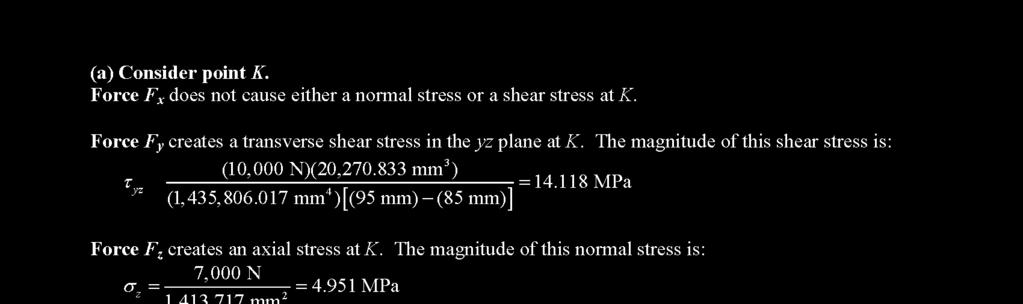
9 (19) Example 11: A hollow structural steel flexural member is subjected to the load shown. The yield strength of the steel is σy = 320 MPa. (a) Determine the factors of safety predicted at point K by the maximum-shear-stress theory of failure. (b) Determine the Mises equivalent stresses at point K. (c) Determine the factors of safety at point K predicted by the maximum-distortion-energy theory. 225 kn V = 225 kn M = 225 kn 1m = 225 knm =, = 50, = (150 16)(250 16) = = ( )(50 ) = () = = ( ), = 16, = = (125 4)(8 150) (67 8) 2 = = = ( )( ) = 63.18, (. )(), = ± ( ) +, = (.) ± ( (.) ) = 17.17, ( ) = = ) 2 = = 1.28 = + = (17.17) ( ) + ( ) = 242 ) = = 1.32
10 Example 12: A steel shaft with an outside diameter of 20 mm is supported in flexible bearings at its ends. Two pulleys are keyed to the shaft, and the pulleys carry belt tensions as shown. The yield strength of the steel is 350 MPa.(a) Determine the factors of safety predicted at points H and K by the maximumshear-stress theory of failure. (b) Determine the Mises equivalent stresses at points H and K. (c) Determine the factors of safety at points H and K predicted by the maximumdistortion-energy theory. (20)
11 (21)
12 (22)
13 (23) TBR 6: If the A-36 steel (σy = 250 MPa) pipe has an outer and inner diameter of 30 mm and 20 mm, respectively, determine the factor of safety against yielding of the material at point A according to the maximum-distortion-energy theory.


14 (24) TBR 7: A force P0 applied by a lever arm to the shaft produces stresses at the critical point A having the values shown. Determine the load PS = cs P0 that would cause the shaft to fail according to the maximum-shear-stress theory, and determine the load PD = cd P0 that would cause failure according to the maximum-distortion-energy theory. The shaft is made of steel with σy = 36 ksi.,, 14.14, 10,20 * The stresses at point A are proportional to load Tresca: 2, 36, c S = 1.2 Von Mises: = 2, 36 0 and c D = 1.36 OR = (20) 2 -(-10 20)+(-10) 2 = 26.4 ksi = =
15 (25) TBR 8: A sign is supported by a pipe (σy = 250 MPa) having outer diameter 110 mm and inner diameter 90 mm. The dimensions of the sign are 2.0 m 1.0 m, and its lower edge is 3.0 m above the base. Note that the center of gravity of the sign is 1.05 m from the axis of the pipe. The wind pressure against the sign is 1.5 kpa. Determine factor of safety based on Tresca and von Mises (maximumdistortion-energy theory) criterions at points A, B, and C. Tresca: FS = (250/2)/76 = 1.64 Tresca: FS = (250/2)/19.94 = 6.26 Tresca: FS = (250/2)/23.7 = 5.27
16 TBR 9: A steel shaft with an outside diameter of 20 mm is supported in flexible bearings at its ends. Two pulleys are keyed to the shaft, and the pulleys carry belt tensions as shown. The yield strength of the steel is σy = 350 MPa. Determine the factors of safety predicted at points H and K by the maximum-shear-stress theory and by the maximum-distortion-energy theory. (26)
17 (27)
 No yielding for brittle conditions so caution is required For Brittle")
.")

18 (28) Failure (Fracture) Criteria for Brittle Materials under Plane Stress For uniaxial tensile test failure occurs when σ = σu (ultimate stress). For plane stress conditions a criterion needs to be defined Maximum-Normal-Stress Criterion (Coulomb s or Rankine; Criterion) No yielding for brittle conditions so caution is required For Brittle materials: 1- fracture is due to normal stress and 2- < (e.g., for cast iron = ). Shortcoming: Not good if, < 0. But it shows good agreement with experimental tests if there exists a tensile principal stress or for a brittle material with = (this is seldom due to presence of cracks). σ UT < < = (, ) Mohr s and simplifies Mohr (Coulomb-Mohr) Criterion Applicable when results of various tests on material are available. If both principal stresses are positive, the state of stress is safe as long as σ a<σ UT and σ b<σ UT; if both principal stresses are negative, the state of stress is safe as long as σ a < σ UC and σ b < σ UC. -σ UT -σ UT σ UT τ Failure Envelope C σuc σut σ C2 C3 C1 D Failure Envelope = + = = + Usually More conservative than Mohr s criterion Only when principal stresses have opposite sign For design, incorporating the factor of safety FS, divide all strengths by FS: = =, If principal stresses have the same sign: = (, ) = (, ) Mohr s criteria can be used in ductile conditions in which yield stress in tension and compression are very different as Tresca and von Mises criterions both assume that yield stress in tension and compression are equal.
 + = ± ( ) + 50 = 159.6, 109.6 = Compression test τ (MPa) Tension test 159.6 295 109.6 970 = 1 =1.53-970 -109.6 295 σ (MPa) How to calculate FS using Mohr s circle? State of Stress 159.")
19 (29) Example 13: For a certain point of a cast-iron machine frame the state of stress on an element is as shown. Find factor of safety based on Mohr s criterion (σut = 295 MPa and σuc = 970 MPa)., = ± ( ) + = ± ( ) + 50 = 159.6, = Compression test τ (MPa) Tension test = 1 = σ (MPa) How to calculate FS using Mohr s circle? State of Stress Example 14: The shaft of a femur can be approximated as a hollow cylindrical shaft. The loads that cause femur bones to fracture are axial torque and bending moments. During strenuous activities (e.g., skiing) the femur is subjected to torque of T = 100 Nm. Determine the maximal bending moment M that the bone can support without failure according to maximum normal stress criteria (D = 24 mm, Di = 16 mm, σut = 120 MPa, σuc = 240 MPa). = = = = = = =0;, = ± + = ± = =120 = Based on Coulomb-Mohr: =?? =1


20 (30) Example 15: The cast-aluminum rod shown is made of an alloy for which σut = 60 MPa and σuc = 120 MPa. Using Mohr s criterion, determine the magnitude of the torque T for which failure should be expected. = = , T Nmm Nm τ (MPa) Compression test Envelope Failure Envelope σ (MPa) Tension test
21 (31) Comparison of Yield and Fracture Criteria with Test Data E.P. Popov (1990), page 529 Remark: Pure shear test Principal stress: = = 1 1 = + = 2

22 (32) TBR 10: The cast-aluminum rod shown is made of an alloy for which σut = psi and σuc = psi. Using Mohr s criterion, determine the maximum magnitude of the force F for which factor of safety is equal to 2 at point A (neglect shear stress due to F and only consider bending and torsion stresses at point A). = =, ( =
 and compression (σuc = 650 MPa).")


23 (33) TBR 11: The shown press is made of cast iron having ultimate strength in tension (σut = 170 MPa) and compression (σuc = 650 MPa). Calculate the allowable load P according to the Mohr-Coulomb criteria and based on a factor of safety equal to 2.5. N. A. 190 mm M P = =

24 TBR 12: A 1.25-in.-diameter solid shaft is subjected to an axial force of P = 7,000 lb, a horizontal force of V = 1,400 lb, and a concentrated torque of T = 220 lb-ft, acting in the directions shown. Assume L = 6.0 in. The ultimate failure strengths for this material are 36 ksi in tension and 50 ksi in compression. Use the Mohr failure criterion to evaluate the safety of this component at points H and K. (34)
25 (35)
26 (36)


27 (37) TBR 13: The shaft of a femur can be approximated as a hollow cylindrical shaft. The loads that cause femur bones to fracture are axial torque and bending moments. During strenuous activities (e.g., skiing) the femur is subjected to M = 100 Nm. Determine the maximal torque T that the bone can support without failure according to Coulomb-Mohr criterion and factor of safety of 1.2 (D = 24 mm, Di = 16 mm, σ ut = 120 MPa, σ uc = 240 MPa). = = = = = =0;, = =91.8 Based on Coulomb-Mohr: ± + =45.9± =. = 1 1.2
 Determine factor of safety at point K according to Tresca and Mises criterion.")
28 (38) TBR 14: A pipe (σy = 95 MPa) with an outside diameter of 140 mm and a wall thickness of 5 mm is subjected to the loadings shown. The internal pressure in the pipe is 1,600 kpa. (a) Determine factor of safety at point K according to Tresca and Mises criterion. (b) if the structure is put in the brittle conditions find factor of safety at point H according to Coulomb-Mohr criterion ( σut = 80 MPa, σuc = 160 MPa).
29 (39)

 if the structure is put in the brittle conditions find factor of safety at point H")
30 TBR 15: A pipe (σy = 250 MPa) with an outside diameter of 95 mm and a wall thickness of 5 mm is subjected to the loadings shown. (a) Determine factor of safety at point K according to Tresca and Mises criterion. (b) if the structure is put in the brittle conditions find factor of safety at point H according to Coulomb-Mohr criterion ( σut = 250 MPa, σuc = 400 MPa). (40)
31 (41)


32 (42) TBR 16: For a given brittle material under torsion the maximal shear stress is equal to 80 MPa. Moreover, the material fails under loading condition (1). Find factor of safety for this material under loading condition (2) (use Mohr s criterion). :, : :,,.,....
Failure surface according to maximum principal stress theory
 Maximum Principal Stress Theory (W. Rankin s Theory- 1850) Brittle Material The maximum principal stress criterion: Rankin stated max principal stress theory as follows- a material fails by fracturing
Failure from static loading
 Failure from static loading Topics Quiz /1/07 Failures from static loading Reading Chapter 5 Homework HW 3 due /1 HW 4 due /8 What is Failure? Failure any change in a machine part which makes it unable
Static Failure (pg 206)
") Static Failure (pg 06) All material followed Hookeʹs law which states that strain is proportional to stress applied, until it exceed the proportional limits. It will reach and exceed the elastic limit
Static Failure (pg 06) All material followed Hookeʹs law which states that strain is proportional to stress applied, until it exceed the proportional limits. It will reach and exceed the elastic limit
Module 5: Theories of Failure
 Module 5: Theories of Failure Objectives: The objectives/outcomes of this lecture on Theories of Failure is to enable students for 1. Recognize loading on Structural Members/Machine elements and allowable
Pressure Vessels Stresses Under Combined Loads Yield Criteria for Ductile Materials and Fracture Criteria for Brittle Materials
 Pressure Vessels Stresses Under Combined Loads Yield Criteria for Ductile Materials and Fracture Criteria for Brittle Materials Pressure Vessels: In the previous lectures we have discussed elements subjected
MAE 322 Machine Design. Dr. Hodge Jenkins Mercer University
 MAE 322 Machine Design Dr. Hodge Jenkins Mercer University What is this Machine Design course really about? What you will learn: How to design machine elements 1) Design so they won t break under varying
Use Hooke s Law (as it applies in the uniaxial direction),
,") 0.6 STRSS-STRAIN RLATIONSHIP Use the principle of superposition Use Poisson s ratio, v lateral longitudinal Use Hooke s Law (as it applies in the uniaxial direction), x x v y z, y y vx z, z z vx y Copyright
0.6 STRSS-STRAIN RLATIONSHIP Use the principle of superposition Use Poisson s ratio, v lateral longitudinal Use Hooke s Law (as it applies in the uniaxial direction), x x v y z, y y vx z, z z vx y Copyright
Stress Analysis Lecture 3 ME 276 Spring Dr./ Ahmed Mohamed Nagib Elmekawy
 Stress Analysis Lecture 3 ME 276 Spring 2017-2018 Dr./ Ahmed Mohamed Nagib Elmekawy Axial Stress 2 Beam under the action of two tensile forces 3 Beam under the action of two tensile forces 4 Shear Stress
FME461 Engineering Design II
 FME461 Engineering Design II Dr.Hussein Jama Hussein.jama@uobi.ac.ke Office 414 Lecture: Mon 8am -10am Tutorial Tue 3pm - 5pm 10/1/2013 1 Semester outline Date Week Topics Reference Reading 9 th Sept 1
Donald P. Shiley School of Engineering ME 328 Machine Design, Spring 2019 Assignment 1 Review Questions
 Donald P. Shiley School of Engineering ME 328 Machine Design, Spring 2019 Assignment 1 Review Questions Name: This is assignment is in workbook format, meaning you may fill in the blanks (you do not need
Structural Analysis I Chapter 4 - Torsion TORSION
 ORSION orsional stress results from the action of torsional or twisting moments acting about the longitudinal axis of a shaft. he effect of the application of a torsional moment, combined with appropriate
Determine the resultant internal loadings acting on the cross section at C of the beam shown in Fig. 1 4a.
 E X M P L E 1.1 Determine the resultant internal loadings acting on the cross section at of the beam shown in Fig. 1 a. 70 N/m m 6 m Fig. 1 Support Reactions. This problem can be solved in the most direct
EMA 3702 Mechanics & Materials Science (Mechanics of Materials) Chapter 3 Torsion
 Chapter 3 Torsion") EMA 3702 Mechanics & Materials Science (Mechanics of Materials) Chapter 3 Torsion Introduction Stress and strain in components subjected to torque T Circular Cross-section shape Material Shaft design Non-circular
EMA 3702 Mechanics & Materials Science (Mechanics of Materials) Chapter 3 Torsion Introduction Stress and strain in components subjected to torque T Circular Cross-section shape Material Shaft design Non-circular
ME Final Exam. PROBLEM NO. 4 Part A (2 points max.) M (x) y. z (neutral axis) beam cross-sec+on. 20 kip ft. 0.2 ft. 10 ft. 0.1 ft.
 M (x) y. z (neutral axis) beam cross-sec+on. 20 kip ft. 0.2 ft. 10 ft. 0.1 ft.") ME 323 - Final Exam Name December 15, 2015 Instructor (circle) PROEM NO. 4 Part A (2 points max.) Krousgrill 11:30AM-12:20PM Ghosh 2:30-3:20PM Gonzalez 12:30-1:20PM Zhao 4:30-5:20PM M (x) y 20 kip ft 0.2
ME 323 - Final Exam Name December 15, 2015 Instructor (circle) PROEM NO. 4 Part A (2 points max.) Krousgrill 11:30AM-12:20PM Ghosh 2:30-3:20PM Gonzalez 12:30-1:20PM Zhao 4:30-5:20PM M (x) y 20 kip ft 0.2
Bone Tissue Mechanics
 Bone Tissue Mechanics João Folgado Paulo R. Fernandes Instituto Superior Técnico, 2016 PART 1 and 2 Introduction The objective of this course is to study basic concepts on hard tissue mechanics. Hard tissue
Principal Stresses, Yielding Criteria, wall structures
 Principal Stresses, Yielding Criteria, St i thi Stresses in thin wall structures Introduction The most general state of stress at a point may be represented by 6 components, x, y, z τ xy, τ yz, τ zx normal
MAE 322 Machine Design Lecture 2. Dr. Hodge Jenkins Mercer University
 MAE 322 Machine Design Lecture 2 Dr. Hodge Jenkins Mercer University Statics Load Failure Theories to Understand Maximum Normal Stress (MNS) Maximum Shear Stress (MSS) Distortion Energy (DE) Coulomb-Mohr
Spherical Pressure Vessels
 Spherical Pressure Vessels Pressure vessels are closed structures containing liquids or gases under essure. Examples include tanks, pipes, essurized cabins, etc. Shell structures : When essure vessels
Stress Transformation Equations: u = +135 (Fig. a) s x = 80 MPa s y = 0 t xy = 45 MPa. we obtain, cos u + t xy sin 2u. s x = s x + s y.
 s x = 80 MPa s y = 0 t xy = 45 MPa. we obtain, cos u + t xy sin 2u. s x = s x + s y.") 014 Pearson Education, Inc., Upper Saddle River, NJ. All rights reserved. This material is protected under all copyright laws as they currently 9 7. Determine the normal stress and shear stress acting
014 Pearson Education, Inc., Upper Saddle River, NJ. All rights reserved. This material is protected under all copyright laws as they currently 9 7. Determine the normal stress and shear stress acting
PROBLEM #1.1 (4 + 4 points, no partial credit)
") PROBLEM #1.1 ( + points, no partial credit A thermal switch consists of a copper bar which under elevation of temperature closes a gap and closes an electrical circuit. The copper bar possesses a length
PROBLEM #1.1 ( + points, no partial credit A thermal switch consists of a copper bar which under elevation of temperature closes a gap and closes an electrical circuit. The copper bar possesses a length
2.1 Background of Piping Stresses
 2 Research Review One of the major additions to Tmin was the inclusion of analysis of a 2-Dimensional vertical piping span. The original plan from Dupont was to include several types of 2-D and 3-D vertical
QUESTION BANK SEMESTER: III SUBJECT NAME: MECHANICS OF SOLIDS
 QUESTION BANK SEMESTER: III SUBJECT NAME: MECHANICS OF SOLIDS UNIT 1- STRESS AND STRAIN PART A (2 Marks) 1. Define longitudinal strain and lateral strain. 2. State Hooke s law. 3. Define modular ratio,
(48) CHAPTER 3: TORSION
 CHAPTER 3: TORSION") (48) CHAPTER 3: TORSION Introduction: In this chapter structural members and machine parts that are in torsion will be considered. More specifically, you will analyze the stresses and strains in members
(48) CHAPTER 3: TORSION Introduction: In this chapter structural members and machine parts that are in torsion will be considered. More specifically, you will analyze the stresses and strains in members
CHAPTER 4: BENDING OF BEAMS
 (74) CHAPTER 4: BENDING OF BEAMS This chapter will be devoted to the analysis of prismatic members subjected to equal and opposite couples M and M' acting in the same longitudinal plane. Such members are
Solid Mechanics Homework Answers
 Name: Date: Solid Mechanics Homework nswers Please show all of your work, including which equations you are using, and circle your final answer. Be sure to include the units in your answers. 1. The yield
NORMAL STRESS. The simplest form of stress is normal stress/direct stress, which is the stress perpendicular to the surface on which it acts.
 NORMAL STRESS The simplest form of stress is normal stress/direct stress, which is the stress perpendicular to the surface on which it acts. σ = force/area = P/A where σ = the normal stress P = the centric
Please review the following statement: I certify that I have not given unauthorized aid nor have I received aid in the completion of this exam.
 Group Number: Please review the following statement: I certify that I have not given unauthorized aid nor have I received aid in the completion of this exam. Signature: INSTRUCTIONS Begin each problem
Mechanical Design. Design of Shaft
 Mechanical Design Design of Shaft Outline Practical information Shaft design Definition of shaft? It is a rotating member, in general, has a circular cross-section and is used to transmit power. The shaft
I certify that I have not given unauthorized aid nor have I received aid in the completion of this exam.
 NAME: ME 270 Fall 2012 Examination No. 3 - Makeup Please review the following statement: Group No.: I certify that I have not given unauthorized aid nor have I received aid in the completion of this exam.
Plasticity R. Chandramouli Associate Dean-Research SASTRA University, Thanjavur
 Plasticity R. Chandramouli Associate Dean-Research SASTRA University, Thanjavur-613 401 Joint Initiative of IITs and IISc Funded by MHRD Page 1 of 9 Table of Contents 1. Plasticity:... 3 1.1 Plastic Deformation,
QUESTION BANK DEPARTMENT: CIVIL SEMESTER: III SUBJECT CODE: CE2201 SUBJECT NAME: MECHANICS OF SOLIDS UNIT 1- STRESS AND STRAIN PART A
 DEPARTMENT: CIVIL SUBJECT CODE: CE2201 QUESTION BANK SEMESTER: III SUBJECT NAME: MECHANICS OF SOLIDS UNIT 1- STRESS AND STRAIN PART A (2 Marks) 1. Define longitudinal strain and lateral strain. 2. State
Structural Metals Lab 1.2. Torsion Testing of Structural Metals. Standards ASTM E143: Shear Modulus at Room Temperature
 Torsion Testing of Structural Metals Standards ASTM E143: Shear Modulus at Room Temperature Purpose To determine the shear modulus of structural metals Equipment Tinius-Olsen Lo-Torq Torsion Machine (figure
MAAE 2202 A. Come to the PASS workshop with your mock exam complete. During the workshop you can work with other students to review your work.
 It is most beneficial to you to write this mock final exam UNDER EXAM CONDITIONS. This means: Complete the exam in 3 hours. Work on your own. Keep your textbook closed. Attempt every question. After the
High Tech High Top Hat Technicians. An Introduction to Solid Mechanics. Is that supposed to bend there?
 High Tech High Top Hat Technicians An Introduction to Solid Mechanics Or Is that supposed to bend there? Why don't we fall through the floor? The power of any Spring is in the same proportion with the
R13. II B. Tech I Semester Regular Examinations, Jan MECHANICS OF SOLIDS (Com. to ME, AME, AE, MTE) PART-A
 PART-A") SET - 1 II B. Tech I Semester Regular Examinations, Jan - 2015 MECHANICS OF SOLIDS (Com. to ME, AME, AE, MTE) Time: 3 hours Max. Marks: 70 Note: 1. Question Paper consists of two parts (Part-A and Part-B)
SET - 1 II B. Tech I Semester Regular Examinations, Jan - 2015 MECHANICS OF SOLIDS (Com. to ME, AME, AE, MTE) Time: 3 hours Max. Marks: 70 Note: 1. Question Paper consists of two parts (Part-A and Part-B)
Downloaded from Downloaded from / 1
 PURWANCHAL UNIVERSITY III SEMESTER FINAL EXAMINATION-2002 LEVEL : B. E. (Civil) SUBJECT: BEG256CI, Strength of Material Full Marks: 80 TIME: 03:00 hrs Pass marks: 32 Candidates are required to give their
ME111 Instructor: Peter Pinsky Class #21 November 13, 2000
 Toda s Topics ME Instructor: Peter Pinsk Class # November,. Consider two designs of a lug wrench for an automobile: (a) single ended, (b) double ended. The distance between points A and B is in. and the
D : SOLID MECHANICS. Q. 1 Q. 9 carry one mark each.
 GTE 2016 Q. 1 Q. 9 carry one mark each. D : SOLID MECHNICS Q.1 single degree of freedom vibrating system has mass of 5 kg, stiffness of 500 N/m and damping coefficient of 100 N-s/m. To make the system
Mechanics of Materials MENG 270 Fall 2003 Exam 3 Time allowed: 90min. Q.1(a) Q.1 (b) Q.2 Q.3 Q.4 Total
 Q.1 (b) Q.2 Q.3 Q.4 Total") Mechanics of Materials MENG 70 Fall 00 Eam Time allowed: 90min Name. Computer No. Q.(a) Q. (b) Q. Q. Q.4 Total Problem No. (a) [5Points] An air vessel is 500 mm average diameter and 0 mm thickness, the
Mechanics of Materials MENG 70 Fall 00 Eam Time allowed: 90min Name. Computer No. Q.(a) Q. (b) Q. Q. Q.4 Total Problem No. (a) [5Points] An air vessel is 500 mm average diameter and 0 mm thickness, the
D : SOLID MECHANICS. Q. 1 Q. 9 carry one mark each. Q.1 Find the force (in kn) in the member BH of the truss shown.
 in the member BH of the truss shown.") D : SOLID MECHANICS Q. 1 Q. 9 carry one mark each. Q.1 Find the force (in kn) in the member BH of the truss shown. Q.2 Consider the forces of magnitude F acting on the sides of the regular hexagon having
D : SOLID MECHANICS Q. 1 Q. 9 carry one mark each. Q.1 Find the force (in kn) in the member BH of the truss shown. Q.2 Consider the forces of magnitude F acting on the sides of the regular hexagon having
ME 202 STRENGTH OF MATERIALS SPRING 2014 HOMEWORK 4 SOLUTIONS
 ÇANKAYA UNIVERSITY MECHANICAL ENGINEERING DEPARTMENT ME 202 STRENGTH OF MATERIALS SPRING 2014 Due Date: 1 ST Lecture Hour of Week 12 (02 May 2014) Quiz Date: 3 rd Lecture Hour of Week 12 (08 May 2014)
UNIT-I STRESS, STRAIN. 1. A Member A B C D is subjected to loading as shown in fig determine the total elongation. Take E= 2 x10 5 N/mm 2
 UNIT-I STRESS, STRAIN 1. A Member A B C D is subjected to loading as shown in fig determine the total elongation. Take E= 2 x10 5 N/mm 2 Young s modulus E= 2 x10 5 N/mm 2 Area1=900mm 2 Area2=400mm 2 Area3=625mm
2. Rigid bar ABC supports a weight of W = 50 kn. Bar ABC is pinned at A and supported at B by rod (1). What is the axial force in rod (1)?
. What is the axial force in rod (1)?") IDE 110 S08 Test 1 Name: 1. Determine the internal axial forces in segments (1), (2) and (3). (a) N 1 = kn (b) N 2 = kn (c) N 3 = kn 2. Rigid bar ABC supports a weight of W = 50 kn. Bar ABC is pinned at
IDE 110 S08 Test 1 Name: 1. Determine the internal axial forces in segments (1), (2) and (3). (a) N 1 = kn (b) N 2 = kn (c) N 3 = kn 2. Rigid bar ABC supports a weight of W = 50 kn. Bar ABC is pinned at
DEPARTMENT OF CIVIL ENGINEERING
 KINGS COLLEGE OF ENGINEERING DEPARTMENT OF CIVIL ENGINEERING SUBJECT: CE 2252 STRENGTH OF MATERIALS UNIT: I ENERGY METHODS 1. Define: Strain Energy When an elastic body is under the action of external
Direct and Shear Stress
 Direct and Shear Stress 1 Direct & Shear Stress When a body is pulled by a tensile force or crushed by a compressive force, the loading is said to be direct. Direct stresses are also found to arise when
SRI CHANDRASEKHARENDRA SARASWATHI VISWA MAHAVIDHYALAYA
 SRI CHANDRASEKHARENDRA SARASWATHI VISWA MAHAVIDHYALAYA (Declared as Deemed-to-be University under Section 3 of the UGC Act, 1956, Vide notification No.F.9.9/92-U-3 dated 26 th May 1993 of the Govt. of
Tuesday, February 11, Chapter 3. Load and Stress Analysis. Dr. Mohammad Suliman Abuhaiba, PE
 1 Chapter 3 Load and Stress Analysis 2 Chapter Outline Equilibrium & Free-Body Diagrams Shear Force and Bending Moments in Beams Singularity Functions Stress Cartesian Stress Components Mohr s Circle for
MECE 3321 MECHANICS OF SOLIDS CHAPTER 1
 MECE 3321 MECHANICS O SOLIDS CHAPTER 1 Samantha Ramirez, MSE WHAT IS MECHANICS O MATERIALS? Rigid Bodies Statics Dynamics Mechanics Deformable Bodies Solids/Mech. Of Materials luids 1 WHAT IS MECHANICS
[5] Stress and Strain
![[5] Stress and Strain](/thumbs/95/123344550.jpg "[5] Stress and Strain") [5] Stress and Strain Page 1 of 34 [5] Stress and Strain [5.1] Internal Stress of Solids [5.2] Design of Simple Connections (will not be covered in class) [5.3] Deformation and Strain [5.4] Hooke s Law
[5] Stress and Strain Page 1 of 34 [5] Stress and Strain [5.1] Internal Stress of Solids [5.2] Design of Simple Connections (will not be covered in class) [5.3] Deformation and Strain [5.4] Hooke s Law
STRENGTH OF MATERIALS-I. Unit-1. Simple stresses and strains
 STRENGTH OF MATERIALS-I Unit-1 Simple stresses and strains 1. What is the Principle of surveying 2. Define Magnetic, True & Arbitrary Meridians. 3. Mention different types of chains 4. Differentiate between
KINGS COLLEGE OF ENGINEERING DEPARTMENT OF MECHANICAL ENGINEERING QUESTION BANK. Subject code/name: ME2254/STRENGTH OF MATERIALS Year/Sem:II / IV
 KINGS COLLEGE OF ENGINEERING DEPARTMENT OF MECHANICAL ENGINEERING QUESTION BANK Subject code/name: ME2254/STRENGTH OF MATERIALS Year/Sem:II / IV UNIT I STRESS, STRAIN DEFORMATION OF SOLIDS PART A (2 MARKS)
DESIGN FOR FATIGUE STRENGTH
 UNIT 3 DESIGN FOR FATIGUE STRENGTH Instructional Objectives Mean and variable stresses and endurance limit. S-N plots for metals and non-metals and relation between endurance limit and ultimate tensile
Tutorial #1 - CivE. 205 Name: I.D:
 Tutorial # - CivE. 0 Name: I.D: Eercise : For the Beam below: - Calculate the reactions at the supports and check the equilibrium of point a - Define the points at which there is change in load or beam
Mechanics of Materials II. Chapter III. A review of the fundamental formulation of stress, strain, and deflection
 Mechanics of Materials II Chapter III A review of the fundamental formulation of stress, strain, and deflection Outline Introduction Assumtions and limitations Axial loading Torsion of circular shafts
IDE 110 Mechanics of Materials Spring 2006 Final Examination FOR GRADING ONLY
 Spring 2006 Final Examination STUDENT S NAME (please print) STUDENT S SIGNATURE STUDENT NUMBER IDE 110 CLASS SECTION INSTRUCTOR S NAME Do not turn this page until instructed to start. Write your name on
Samantha Ramirez, MSE. Stress. The intensity of the internal force acting on a specific plane (area) passing through a point. F 2
 passing through a point. F 2") Samantha Ramirez, MSE Stress The intensity of the internal force acting on a specific plane (area) passing through a point. Δ ΔA Δ z Δ 1 2 ΔA Δ x Δ y ΔA is an infinitesimal size area with a uniform force
Samantha Ramirez, MSE Stress The intensity of the internal force acting on a specific plane (area) passing through a point. Δ ΔA Δ z Δ 1 2 ΔA Δ x Δ y ΔA is an infinitesimal size area with a uniform force
MECHANICS OF MATERIALS
 GE SI CHAPTER 3 MECHANICS OF MATERIALS Ferdinand P. Beer E. Russell Johnston, Jr. John T. DeWolf David F. Mazurek Torsion Lecture Notes: J. Walt Oler Texas Tech University Torsional Loads on Circular Shafts
and F NAME: ME rd Sample Final Exam PROBLEM 1 (25 points) Prob. 1 questions are all or nothing. PROBLEM 1A. (5 points)
 Prob. 1 questions are all or nothing. PROBLEM 1A. (5 points)") ME 270 3 rd Sample inal Exam PROBLEM 1 (25 points) Prob. 1 questions are all or nothing. PROBLEM 1A. (5 points) IND: In your own words, please state Newton s Laws: 1 st Law = 2 nd Law = 3 rd Law = PROBLEM
ME 270 3 rd Sample inal Exam PROBLEM 1 (25 points) Prob. 1 questions are all or nothing. PROBLEM 1A. (5 points) IND: In your own words, please state Newton s Laws: 1 st Law = 2 nd Law = 3 rd Law = PROBLEM
Name :. Roll No. :... Invigilator s Signature :.. CS/B.TECH (CE-NEW)/SEM-3/CE-301/ SOLID MECHANICS
/SEM-3/CE-301/ SOLID MECHANICS") Name :. Roll No. :..... Invigilator s Signature :.. 2011 SOLID MECHANICS Time Allotted : 3 Hours Full Marks : 70 The figures in the margin indicate full marks. Candidates are required to give their answers
Name :. Roll No. :..... Invigilator s Signature :.. 2011 SOLID MECHANICS Time Allotted : 3 Hours Full Marks : 70 The figures in the margin indicate full marks. Candidates are required to give their answers
If the solution does not follow a logical thought process, it will be assumed in error.
 Please indicate your group number (If applicable) Circle Your Instructor s Name and Section: MWF 8:30-9:20 AM Prof. Kai Ming Li MWF 2:30-3:20 PM Prof. Fabio Semperlotti MWF 9:30-10:20 AM Prof. Jim Jones
CE6306 STRENGTH OF MATERIALS TWO MARK QUESTIONS WITH ANSWERS ACADEMIC YEAR
 CE6306 STRENGTH OF MATERIALS TWO MARK QUESTIONS WITH ANSWERS ACADEMIC YEAR 2014-2015 UNIT - 1 STRESS, STRAIN AND DEFORMATION OF SOLIDS PART- A 1. Define tensile stress and tensile strain. The stress induced
Aluminum shell. Brass core. 40 in
 PROBLEM #1 (22 points) A solid brass core is connected to a hollow rod made of aluminum. Both are attached at each end to a rigid plate as shown in Fig. 1. The moduli of aluminum and brass are EA=11,000
Introduction to Engineering Materials ENGR2000. Dr. Coates
 Introduction to Engineering Materials ENGR2 Chapter 6: Mechanical Properties of Metals Dr. Coates 6.2 Concepts of Stress and Strain tension compression shear torsion Tension Tests The specimen is deformed
PERIYAR CENTENARY POLYTECHNIC COLLEGE PERIYAR NAGAR - VALLAM THANJAVUR. DEPARTMENT OF MECHANICAL ENGINEERING QUESTION BANK
 PERIYAR CENTENARY POLYTECHNIC COLLEGE PERIYAR NAGAR - VALLAM - 613 403 - THANJAVUR. DEPARTMENT OF MECHANICAL ENGINEERING QUESTION BANK Sub : Strength of Materials Year / Sem: II / III Sub Code : MEB 310
Mechanical Engineering Ph.D. Preliminary Qualifying Examination Solid Mechanics February 25, 2002
 student personal identification (ID) number on each sheet. Do not write your name on any sheet. #1. A homogeneous, isotropic, linear elastic bar has rectangular cross sectional area A, modulus of elasticity
ENT345 Mechanical Components Design
 1) LOAD AND STRESS ANALYSIS i. Principle stress ii. The maximum shear stress iii. The endurance strength of shaft. 1) Problem 3-71 A countershaft carrying two-v belt pulleys is shown in the figure. Pulley
MECHANICS OF MATERIALS
 2009 The McGraw-Hill Companies, Inc. All rights reserved. Fifth SI Edition CHAPTER 3 MECHANICS OF MATERIALS Ferdinand P. Beer E. Russell Johnston, Jr. John T. DeWolf David F. Mazurek Torsion Lecture Notes:
PDDC 1 st Semester Civil Engineering Department Assignments of Mechanics of Solids [ ] Introduction, Fundamentals of Statics
![PDDC 1 st Semester Civil Engineering Department Assignments of Mechanics of Solids [ ] Introduction, Fundamentals of Statics](/thumbs/92/109382806.jpg "PDDC 1 st Semester Civil Engineering Department Assignments of Mechanics of Solids [ ] Introduction, Fundamentals of Statics") Page1 PDDC 1 st Semester Civil Engineering Department Assignments of Mechanics of Solids [2910601] Introduction, Fundamentals of Statics 1. Differentiate between Scalar and Vector quantity. Write S.I.
Page1 PDDC 1 st Semester Civil Engineering Department Assignments of Mechanics of Solids [2910601] Introduction, Fundamentals of Statics 1. Differentiate between Scalar and Vector quantity. Write S.I.
University of Pretoria Department of Mechanical & Aeronautical Engineering MOW 227, 2 nd Semester 2014
 Universit of Pretoria Department of Mechanical & Aeronautical Engineering MOW 7, nd Semester 04 Semester Test Date: August, 04 Total: 00 Internal eaminer: Duration: hours Mr. Riaan Meeser Instructions:
CE 221: MECHANICS OF SOLIDS I CHAPTER 1: STRESS. Dr. Krisada Chaiyasarn Department of Civil Engineering, Faculty of Engineering Thammasat university
 CE 221: MECHANICS OF SOLIDS I CHAPTER 1: STRESS By Dr. Krisada Chaiyasarn Department of Civil Engineering, Faculty of Engineering Thammasat university Agenda Introduction to your lecturer Introduction
Chapter 8 Structural Design and Analysis. Strength and stiffness 5 types of load: Tension Compression Shear Bending Torsion
 Chapter 8 Structural Design and Analysis 1 Strength and stiffness 5 types of load: Tension Compression Shear Bending Torsion Normal Stress Stress is a state when a material is loaded. For normal forces
STRESS, STRAIN AND DEFORMATION OF SOLIDS
 VELAMMAL COLLEGE OF ENGINEERING AND TECHNOLOGY, MADURAI 625009 DEPARTMENT OF CIVIL ENGINEERING CE8301 STRENGTH OF MATERIALS I -------------------------------------------------------------------------------------------------------------------------------
Prof. B V S Viswanadham, Department of Civil Engineering, IIT Bombay
 51 Module 4: Lecture 2 on Stress-strain relationship and Shear strength of soils Contents Stress state, Mohr s circle analysis and Pole, Principal stressspace, Stress pathsin p-q space; Mohr-coulomb failure
7.6 Stress in symmetrical elastic beam transmitting both shear force and bending moment
 7.6 Stress in symmetrical elastic beam transmitting both shear force and bending moment à It is more difficult to obtain an exact solution to this problem since the presence of the shear force means that
CIV E 205 Mechanics of Solids II. Course Notes
 Department of Civil Engineering CIV E 205 Mechanics of Solids II Instructor: Tarek Hegazi Email: tarek@uwaterloo.ca Course Notes Mechanics of Materials Objectives: - Solve Problems in a structured systematic
PES Institute of Technology
 PES Institute of Technology Bangalore south campus, Bangalore-5460100 Department of Mechanical Engineering Faculty name : Madhu M Date: 29/06/2012 SEM : 3 rd A SEC Subject : MECHANICS OF MATERIALS Subject
Solution: The moment of inertia for the cross-section is: ANS: ANS: Problem 15.6 The material of the beam in Problem
 Problem 15.4 The beam consists of material with modulus of elasticity E 14x10 6 psi and is subjected to couples M 150, 000 in lb at its ends. (a) What is the resulting radius of curvature of the neutral
σ = Eα(T T C PROBLEM #1.1 (4 + 4 points, no partial credit)
") PROBLEM #1.1 (4 + 4 points, no partial credit A thermal switch consists of a copper bar which under elevation of temperature closes a gap and closes an electrical circuit. The copper bar possesses a length
PROBLEM #1.1 (4 + 4 points, no partial credit A thermal switch consists of a copper bar which under elevation of temperature closes a gap and closes an electrical circuit. The copper bar possesses a length
BME 207 Introduction to Biomechanics Spring 2017
 April 7, 2017 UNIVERSITY OF RHODE ISAND Department of Electrical, Computer and Biomedical Engineering BE 207 Introduction to Biomechanics Spring 2017 Homework 7 Problem 14.3 in the textbook. In addition
UNIT 1 STRESS STRAIN AND DEFORMATION OF SOLIDS, STATES OF STRESS 1. Define stress. When an external force acts on a body, it undergoes deformation.
 UNIT 1 STRESS STRAIN AND DEFORMATION OF SOLIDS, STATES OF STRESS 1. Define stress. When an external force acts on a body, it undergoes deformation. At the same time the body resists deformation. The magnitude
MEMS Project 2 Assignment. Design of a Shaft to Transmit Torque Between Two Pulleys
 MEMS 029 Project 2 Assignment Design of a Shaft to Transmit Torque Between Two Pulleys Date: February 5, 206 Instructor: Dr. Stephen Ludwick Product Definition Shafts are incredibly important in order
Chapter 3. Load and Stress Analysis
 Chapter 3 Load and Stress Analysis 2 Shear Force and Bending Moments in Beams Internal shear force V & bending moment M must ensure equilibrium Fig. 3 2 Sign Conventions for Bending and Shear Fig. 3 3
MMJ1133 FATIGUE AND FRACTURE MECHANICS A - INTRODUCTION INTRODUCTION
 A - INTRODUCTION INTRODUCTION M.N.Tamin, CSMLab, UTM Course Content: A - INTRODUCTION Mechanical failure modes; Review of load and stress analysis equilibrium equations, complex stresses, stress transformation,
ME325 EXAM I (Sample)
") ME35 EXAM I (Sample) NAME: NOTE: COSED BOOK, COSED NOTES. ONY A SINGE 8.5x" ORMUA SHEET IS AOWED. ADDITIONA INORMATION IS AVAIABE ON THE AST PAGE O THIS EXAM. DO YOUR WORK ON THE EXAM ONY (NO SCRATCH PAPER
ME35 EXAM I (Sample) NAME: NOTE: COSED BOOK, COSED NOTES. ONY A SINGE 8.5x" ORMUA SHEET IS AOWED. ADDITIONA INORMATION IS AVAIABE ON THE AST PAGE O THIS EXAM. DO YOUR WORK ON THE EXAM ONY (NO SCRATCH PAPER
MECHANICS OF MATERIALS
 00 The McGraw-Hill Companies, Inc. All rights reserved. T Edition CHAPTER MECHANICS OF MATERIALS Ferdinand P. Beer E. Russell Johnston, Jr. John T. DeWolf Lecture Notes: J. Walt Oler Teas Tech Universit
MECE 3321 MECHANICS OF SOLIDS CHAPTER 3
 MECE 3321 MECHANICS OF SOLIDS CHAPTER 3 Samantha Ramirez TENSION AND COMPRESSION TESTS Tension and compression tests are used primarily to determine the relationship between σ avg and ε avg in any material.
Ch 4a Stress, Strain and Shearing
 Ch. 4a - Stress, Strain, Shearing Page 1 Ch 4a Stress, Strain and Shearing Reading Assignment Ch. 4a Lecture Notes Sections 4.1-4.3 (Salgado) Other Materials Handout 4 Homework Assignment 3 Problems 4-13,
Path to static failure of machine components
 Pat to static failure of macine components Load Stress Discussed last week (w) Ductile material Yield Strain Brittle material Fracture Fracture Dr. P. Buyung Kosasi,Spring 008 Name some of ductile and
Tensile stress strain curves for different materials. Shows in figure below
 Tensile stress strain curves for different materials. Shows in figure below Furthermore, the modulus of elasticity of several materials effected by increasing temperature, as is shown in Figure Asst. Lecturer
ME 243. Mechanics of Solids
 ME 243 Mechanics of Solids Lecture 2: Stress and Strain Ahmad Shahedi Shakil Lecturer, Dept. of Mechanical Engg, BUET E-mail: sshakil@me.buet.ac.bd, shakil6791@gmail.com Website: teacher.buet.ac.bd/sshakil
18.Define the term modulus of resilience. May/June Define Principal Stress. 20. Define Hydrostatic Pressure.
 CE6306 STREGNTH OF MATERIALS Question Bank Unit-I STRESS, STRAIN, DEFORMATION OF SOLIDS PART-A 1. Define Poison s Ratio May/June 2009 2. What is thermal stress? May/June 2009 3. Estimate the load carried
ENG1001 Engineering Design 1
 ENG1001 Engineering Design 1 Structure & Loads Determine forces that act on structures causing it to deform, bend, and stretch Forces push/pull on objects Structures are loaded by: > Dead loads permanent
Lecture #8: Ductile Fracture (Theory & Experiments)
") Lecture #8: Ductile Fracture (Theory & Experiments) by Dirk Mohr ETH Zurich, Department of Mechanical and Process Engineering, Chair of Computational Modeling of Materials in Manufacturing 2015 1 1 1 Ductile
Lecture #8: Ductile Fracture (Theory & Experiments) by Dirk Mohr ETH Zurich, Department of Mechanical and Process Engineering, Chair of Computational Modeling of Materials in Manufacturing 2015 1 1 1 Ductile
8. Combined Loadings
 CHAPTER OBJECTIVES qanalyze the stress developed in thin-walled pressure vessels qreview the stress analysis developed in previous chapters regarding axial load, torsion, bending and shear qdiscuss the
MATERIALS FOR CIVIL AND CONSTRUCTION ENGINEERS
 MATERIALS FOR CIVIL AND CONSTRUCTION ENGINEERS 3 rd Edition Michael S. Mamlouk Arizona State University John P. Zaniewski West Virginia University Solution Manual FOREWORD This solution manual includes
Solution: T, A1, A2, A3, L1, L2, L3, E1, E2, E3, P are known Five equations in five unknowns, F1, F2, F3, ua and va
 ME 323 Examination # 1 February 18, 2016 Name (Print) (Last) (First) Instructor PROBLEM #1 (20 points) A structure is constructed from members 1, 2 and 3, with these members made up of the same material
Torsional and Bending Stresses in Machine Parts
 10 n A Textbook of Machine Design C 5 H A P T E R Torsional and Bending Stresses in Machine Parts 1. Introduction.. Torsional Shear Stress.. Shafts in Series and Parallel.. Bending Stress in Straight Beams.
MECHANICS OF MATERIALS. Prepared by Engr. John Paul Timola
 MECHANICS OF MATERIALS Prepared by Engr. John Paul Timola Mechanics of materials branch of mechanics that studies the internal effects of stress and strain in a solid body. stress is associated with the
Table of Contents. Preface...xvii. Part 1. Level
 Preface...xvii Part 1. Level 1... 1 Chapter 1. The Basics of Linear Elastic Behavior... 3 1.1. Cohesion forces... 4 1.2. The notion of stress... 6 1.2.1. Definition... 6 1.2.2. Graphical representation...
Russell C. Hibbeler. Chapter 1: Stress
 Russell C. Hibbeler Chapter 1: Stress Introduction Mechanics of materials is a study of the relationship between the external loads on a body and the intensity of the internal loads within the body. This