CHAPTER 6. Inductance, Capacitance, and Mutual Inductance
|
|
|
- Ami George
- 5 years ago
- Views:
Transcription
1 CHAPTER 6 Inductance, Capacitance, and Mutual Inductance
2 6.1 The Inductor Inductance is symbolized by the letter L, is measured in henrys (H), and is represented graphically as a coiled wire. The inductor v - i equation Figure 6.1 (a) The graphic symbol for an inductor with an inductance of L henrys. (b) Assigning reference voltage and current to the inductor, following the passive sign convention.
3 Example 6.1 The independent current source in the circuit shown in Fig. 6.2 generates zero current for t < 0 and a pulse 10te 5t A, for t > 0. Figure 6.2 The circuit for Example 6.1.
4 Example 6.1 a) Sketch the current waveform. b) At what instant of time is the current maximum? c) Express the voltage across the terminals of the 100 mh inductor as a function of time. d) Sketch the voltage waveform. e) Are the voltage and the current at a maximum at the same time? f) At what instant of time does the voltage change polarity? g) Is there ever an instantaneous change in voltage across the inductor? If so, at what time?
5 Example 6.1
6 Example 6.1 Figure 6.3 The current waveform for Example 6.1. Figure 6.4 The voltage waveform for Example 6.1.

7 Current in an Inductor in Terms of the Voltage Across the Inductor The inductor i - v equation
8 Example 6.2 The voltage pulse applied to the 100 mh inductor shown in Fig. 6.5 is t < 0 for and is given by the expression v(t) = 20te 10t V for t > 0. Also assume i = 0 for t 0. a) Sketch the voltage as a function of time. b) Find the inductor current as a function of time. c) Sketch the current as a function of time. Figure 6.5 The circuit for Example 6.2.
9 Example 6.2
10 Example 6.2 Figure 6.6 The voltage waveform for Example 6.2. Figure 6.7 The current waveform for Example 6.2.

11 Power and Energy in the Inductor If the current reference is in the direction of the voltage drop across the terminals of the inductor, the power is Power in an inductor Energy in an inductor
 In what time interval is energy being stored in the inductor? c) In what time interval is energy being extracted from the inductor? d) What is the maximum energy stored in the inductor?")
12 Example 6.3 a) For Example 6.1, plot i, v, p, and versus time. Line up the plots vertically to allow easy assessment of each variable s behavior. b) In what time interval is energy being stored in the inductor? c) In what time interval is energy being extracted from the inductor? d) What is the maximum energy stored in the inductor? e) Evaluate the integrals and comment on their significance. f) Repeat (a) (c) for Example 6.2. g) In Example 6.2, why is there a sustained current in the inductor as the voltage approaches zero?

13 Example 6.3
14 Example 6.3 Figure 6.8 The variables i, υ, p, and w versus t for Example 6.1.
15 Example 6.3

16 Example 6.3


17 Example 6.3
18 Example 6.3 Figure 6.9 The variables i, υ, p, and w versus t for Example 6.2.
19 6.2 The Capacitor The circuit parameter of capacitance is represented by the letter C, is measured in farads (F), and is symbolized graphically by two short parallel conductive plates. Because the farad is an extremely large quantity of capacitance, practical capacitor values usually lie in the picofarad (pf) to microfarad (μf) range.
20 Capacitor i - v equation Figure 6.10 (a) The circuit symbol for a capacitor. (b) Assigning reference voltage and current to the capacitor, following the passive sign convention.

21 Capacitor v - i equation Capacitor power equation Capacitor energy equation
22 Example 6.4 The voltage pulse described by the following equations is impressed across the terminals of a 0.5 mf capacitor: a) Derive the expressions for the capacitor current, power, and energy. b) Sketch the voltage, current, power, and energy as functions of time. Line up the plots vertically. c) Specify the interval of time when energy is being stored in the capacitor.
23 Example 6.4 d) Specify the interval of time when energy is being delivered by the capacitor. e) Evaluate the integrals and comment on their significance
24 Example 6.4

25 Example 6.4
26 Example 6.4
27 Example 6.4 Figure 6.11 The variables i, υ, p, and w versus t for Example 6.4.
28 Example 6.5 An uncharged 0.2 mf capacitor is driven by a triangular current pulse. The current pulse is described by a) Derive the expressions for the capacitor voltage, power, and energy for each of the four time intervals needed to describe the current. b) Plot i, v, p, and w versus t. Align the plots as specified in the previous examples. c) Why does a voltage remain on the capacitor after the current returns to zero?
29 Example 6.5
30 Example 6.5

31 Example 6.5
32 Example 6.5 Figure 6.11 The variables i, υ, p, and w versus t for Example 6.4.
33 6.3 Series-Parallel Combinations of Inductance and Capacitance Combining inductors in series Figure 6.13 Inductors in series. Figure 6.14 An equivalent circuit for inductors in series carrying an initial current i(t 0 ).
34 Figure 6.16 An equivalent circuit for three inductors in parallel. Figure 6.15 Three inductors in parallel.
35 Combining inductors in parallel Equivalent inductance initial current
36 Figure 6.17 An equivalent circuit for capacitors connected in series. (a) The series capacitors. (b) The equivalent circuit.

37 Combining capacitors in series Equivalent capacitance initial voltage
38 Combining capacitors in parallel Figure 6.18 An equivalent circuit for capacitors connected in parallel. (a) Capacitors in parallel. (b) The equivalent circuit.
39 6.4 Mutual Inductance Two circuits are linked by a magnetic field. The voltage induced in the second circuit can be related to the time-varying current in the first circuit by a parameter known as mutual inductance. The self-inductances of the two coils are labeled L 1 and L 2 and the mutual inductance is labeled M.
40 Figure 6.19 Two magnetically coupled coils. Figure 6.20 Coil currents i 1 and i 2 used to describe the circuit shown in Fig
41 Dot convention for mutually coupled coils When the reference direction for a current enters the dotted terminal of a coil, the reference polarity of the voltage that it induces in the other coil is positive at its dotted terminal. Figure 6.21 The circuit of Fig with dots added to the coils indicating the polarity of the mutually induced voltages.
42 Dot convention for mutually coupled coils (alternate) When the reference direction for a current leaves the dotted terminal of a coil, the reference polarity of the voltage that it induces in the other coil is negative at its dotted terminal.
43 In Fig. 6.21, the dot convention rule indicates that the reference polarity for the voltage induced in coil 1 by the current i 2 is negative at the dotted terminal of coil 1.This voltage (Mdi 2 /dt) is a voltage rise with respect to The voltage induced in coil 2 by the current i 1 is Mdi 1 /dt and its reference polarity is positive at the dotted terminal of coil 2.This voltage is a voltage rise in the direction of i 2. Figure 6.22 shows the self- and mutually induced voltages across coils 1 and 2 along with their polarity marks.
44 Figure 6.22 The self- and mutually induced voltages appearing across the coils shown in Fig Now let s look at the sum of the voltages around each closed loop. In Eqs and 6.32, voltage rises in the reference direction of a current are negative:
45 The Procedure for Determining Dot Markings a) Arbitrarily select one terminal b) Assign a current into the dotted terminal and label it c) Use the right-hand rule1 to determine the direction of the magnetic field d) Arbitrarily pick one terminal of the second coil e) Use the right-hand rule to determine the direction of the flux f) Compare the directions of the two fluxes

46 Figure 6.23 A set of coils showing a method for determining a set of dot markings.

47 Figure 6.24 An experimental setup for determining polarity marks.
48 Example 6.6 a) Write a set of mesh-current equations that describe the circuit in Fig in terms of the currents i 1 and i 2. b) Verify that if there is no energy stored in the circuit at t = 0 and if i g = 16 16e 5t A, the solutions for i 1 and i 2 are Figure 6.25 The circuit for Example 6.6.

49 Example 6.6

50 Example 6.6

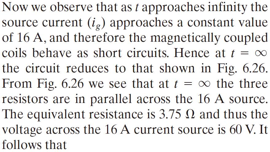
51 Example 6.6 Figure 6.26 The circuit of Example 6.6 when t =.
52 6.5 A Closer Look at Mutual Inductance A Review of Self-Inductance The voltage induced in the conductor is proportional to the number of lines that collapse into, or cut, the conductor. This image of induced voltage is expressed by what is called Faraday s law; Figure 6.27 Representation of a magnetic field linking an N-turn coil.
53 The flux linkage is the product of the magnetic field(f), measured in webers(wb), and the number of turns linked by the field (N): where N is the number of turns on the coil, and P is the permeance of the space occupied by the flux.
54 Here, we assume that the core material the space containing the flux is nonmagnetic. Then, substituting Eqs and 6.35 into Eq yields which shows that self-inductance is proportional to the square of the number of turns on the coil.
55 The Concept of Mutual Inductance Figure 6.28 Two magnetically coupled coils Figure 6.28 Two magnetically coupled coils.
56 The total flux linking coil 1 is f 1, the sum of f 11 and f 12 : The flux f 1 and its components f 11 and f 12 are related to the coil current i 1 as follows: where P 1 is the permeance of the space occupied by the flux f 1, P 11 is the permeance of the space occupied by the flux f 11, and P 21 is the permeance of the space occupied by the flux f 21.
57 Substituting Eqs. 6.38, 6.39, and 6.40 into Eq yields the relationship between the permeance of the space occupied by the total flux f 1 and the permeances of the spaces occupied by its components f 11 and f 21 :
58 We use Faraday s law to derive expressions for v 1 and v 2 : and
59 The coefficient of di 1 /dt in Eq is the selfinductance of coil 1. The coefficient of di 1 /dt in Eq is the mutual inductance between coils 1 and 2.Thus The subscript on M specifies an inductance that relates the voltage induced in coil 2 to the current in coil 1.
60 The coefficient of mutual inductance gives Note that the dot convention is used to assign the polarity reference to v 2 in Fig Figure 6.28 Two magnetically coupled coils.
61 For the coupled coils in Fig. 6.28, exciting coil 2 from a time-varying current source (i 2 ) and leaving coil 1 open produces the circuit arrangement shown in Fig Again, the polarity reference assigned to v 1 is based on the dot convention. Figure 6.29 The magnetically coupled coils of Fig. 6.28, with coil 2 excited and coil 1 open.
62 The total flux linking coil 2 is The flux f 2 and its components f 22 and f 12 are related to the coil current i 2 as follows: The voltages v 1 and v 2 are
63 The coefficient of mutual inductance that relates the voltage induced in coil 1 to the time-varying current in coil 2 is the coefficient of di 2 /dt in Eq. 6.51: For nonmagnetic materials, the permeances P 21 and P 12 are equal, and therefore Hence for linear circuits with just two magnetically coupled coils, attaching subscripts to the coefficient of mutual inductance is not necessary.
64 Mutual Inductance in Terms of Self- Inductance The value of mutual inductance is a function of the self-inductances. We derive this relationship as follows. From Eqs and 6.50, respectively. From Eqs and 6.55,
65 We now use Eq and the corresponding expression for P 2 to write But for a linear system, P 21 = P 12, so Eq becomes
66 Relating self-inductances and mutual inductance using coupling coefficient Replacing the two terms involving permeances by a single constant expresses Eq in a more meaningful form: Substituting Eq into Eq yields or where the constant k is called the coefficient of coupling.
67 Energy Calculations For linear magnetic coupling, If we reverse the procedure that is, if we first increase i 2 from zero to I 2 and then increase i 1 from zero to I 1 the total energy stored is
68 Figure 6.30 The circuit used to derive the basic energy relationships.
69 Energy stored in magnetically-coupled coils
ECE2262 Electric Circuits. Chapter 6: Capacitance and Inductance
 ECE2262 Electric Circuits Chapter 6: Capacitance and Inductance Capacitors Inductors Capacitor and Inductor Combinations 1 CAPACITANCE AND INDUCTANCE Introduces two passive, energy storing devices: Capacitors
ECE2262 Electric Circuits. Chapter 6: Capacitance and Inductance
 ECE2262 Electric Circuits Chapter 6: Capacitance and Inductance Capacitors Inductors Capacitor and Inductor Combinations Op-Amp Integrator and Op-Amp Differentiator 1 CAPACITANCE AND INDUCTANCE Introduces
ENGR 2405 Chapter 6. Capacitors And Inductors
 ENGR 2405 Chapter 6 Capacitors And Inductors Overview This chapter will introduce two new linear circuit elements: The capacitor The inductor Unlike resistors, these elements do not dissipate energy They
Experiment Guide for RC Circuits
 Guide-P1 Experiment Guide for RC Circuits I. Introduction 1. Capacitors A capacitor is a passive electronic component that stores energy in the form of an electrostatic field. The unit of capacitance is
Introduction to AC Circuits (Capacitors and Inductors)
") Introduction to AC Circuits (Capacitors and Inductors) Amin Electronics and Electrical Communications Engineering Department (EECE) Cairo University elc.n102.eng@gmail.com http://scholar.cu.edu.eg/refky/
Introduction to AC Circuits (Capacitors and Inductors) Amin Electronics and Electrical Communications Engineering Department (EECE) Cairo University elc.n102.eng@gmail.com http://scholar.cu.edu.eg/refky/
CHAPTER FOUR MUTUAL INDUCTANCE
 CHAPTER FOUR MUTUAL INDUCTANCE 4.1 Inductance 4.2 Capacitance 4.3 Serial-Parallel Combination 4.4 Mutual Inductance 4.1 Inductance Inductance (L in Henry is the circuit parameter used to describe an inductor.
Circuit Analysis-II. Circuit Analysis-II Lecture # 5 Monday 23 rd April, 18
 Circuit Analysis-II Capacitors in AC Circuits Introduction ü The instantaneous capacitor current is equal to the capacitance times the instantaneous rate of change of the voltage across the capacitor.
Energy Storage Elements: Capacitors and Inductors
 CHAPTER 6 Energy Storage Elements: Capacitors and Inductors To this point in our study of electronic circuits, time has not been important. The analysis and designs we have performed so far have been static,
Electric Circuits I. Inductors. Dr. Firas Obeidat
 Electric Circuits I Inductors Dr. Firas Obeidat 1 Inductors An inductor is a passive element designed to store energy in its magnetic field. They are used in power supplies, transformers, radios, TVs,
Electronics Capacitors
 Electronics Capacitors Wilfrid Laurier University October 9, 2015 Capacitor an electronic device which consists of two conductive plates separated by an insulator Capacitor an electronic device which consists
Chapter 6 Objectives
 hapter 6 Engr8 ircuit Analysis Dr urtis Nelson hapter 6 Objectives Understand relationships between voltage, current, power, and energy in inductors and capacitors; Know that current must be continuous
Basics of Network Theory (Part-I)
") Basics of Network Theory (PartI). A square waveform as shown in figure is applied across mh ideal inductor. The current through the inductor is a. wave of peak amplitude. V 0 0.5 t (m sec) [Gate 987: Marks]
Basics of Network Theory (PartI). A square waveform as shown in figure is applied across mh ideal inductor. The current through the inductor is a. wave of peak amplitude. V 0 0.5 t (m sec) [Gate 987: Marks]
RC, RL, and LCR Circuits
 RC, RL, and LCR Circuits EK307 Lab Note: This is a two week lab. Most students complete part A in week one and part B in week two. Introduction: Inductors and capacitors are energy storage devices. They
3 The non-linear elements
 3.1 Introduction The inductor and the capacitor are the two important passive circuit elements which have the ability to store and deliver finite amount of energy [49]. In an inductor, the energy is stored
Capacitor Construction
 Capacitor Construction Topics covered in this presentation: Capacitor Construction 1 of 13 Introduction to Capacitors A capacitor is a device that is able to store charge and acts like a temporary, rechargeable
Pretest ELEA1831 Module 11 Units 1& 2 Inductance & Capacitance
 Pretest ELEA1831 Module 11 Units 1& 2 Inductance & Capacitance 1. What is Faraday s Law? Magnitude of voltage induced in a turn of wire is proportional to the rate of change of flux passing through that
INDUCTANCE Self Inductance
 NDUTANE 3. Self nductance onsider the circuit shown in the Figure. When the switch is closed the current, and so the magnetic field, through the circuit increases from zero to a specific value. The increasing
Conceptually, a capacitor consists of two conducting plates. Capacitors: Concept
 apacitors and Inductors Overview Defining equations Key concepts and important properties Series and parallel equivalents Integrator Differentiator Portland State University EE 221 apacitors and Inductors
Chapter 29. Electric Potential: Charged Conductor
 hapter 29 Electric Potential: harged onductor 1 Electric Potential: harged onductor onsider two points (A and B) on the surface of the charged conductor E is always perpendicular to the displacement ds
Electric Circuits Fall 2015 Solution #5
 RULES: Please try to work on your own. Discussion is permissible, but identical submissions are unacceptable! Please show all intermeate steps: a correct solution without an explanation will get zero cret.
Chapter 30 Inductance and Electromagnetic Oscillations
 Chapter 30 Inductance and Electromagnetic Oscillations Units of Chapter 30 30.1 Mutual Inductance: 1 30.2 Self-Inductance: 2, 3, & 4 30.3 Energy Stored in a Magnetic Field: 5, 6, & 7 30.4 LR Circuit: 8,
Electromagnetic Induction Faraday s Law Lenz s Law Self-Inductance RL Circuits Energy in a Magnetic Field Mutual Inductance
 Lesson 7 Electromagnetic Induction Faraday s Law Lenz s Law Self-Inductance RL Circuits Energy in a Magnetic Field Mutual Inductance Oscillations in an LC Circuit The RLC Circuit Alternating Current Electromagnetic
ASSOCIATE DEGREE IN ENGINEERING RESIT EXAMINATIONS SEMESTER 1. "Electrical Eng Science"
 ASSOCIATE DEGREE IN ENGINEERING RESIT EXAMINATIONS SEMESTER 1 COURSE NAME: "Electrical Eng Science" CODE: GROUP: "[ADET 2]" DATE: December 2010 TIME: DURATION: 9:00 am "Two hours" INSTRUCTIONS: 1. This
6. Introduction and Chapter Objectives
 Real Analog - Circuits Chapter 6: Energy Storage Elements 6. Introduction and Chapter Objectives So far, we have considered circuits that have been governed by algebraic relations. These circuits have,
CIRCUIT ELEMENT: CAPACITOR
 CIRCUIT ELEMENT: CAPACITOR PROF. SIRIPONG POTISUK ELEC 308 Types of Circuit Elements Two broad types of circuit elements Ati Active elements -capable of generating electric energy from nonelectric energy
Chapter 26. Capacitance and Dielectrics
 Chapter 26 Capacitance and Dielectrics Capacitors Capacitors are devices that store electric charge Examples of where capacitors are used include: radio receivers filters in power supplies energy-storing
ELECTROMAGNETIC INDUCTION AND FARADAY S LAW
 ELECTROMAGNETIC INDUCTION AND FARADAY S LAW Magnetic Flux The emf is actually induced by a change in the quantity called the magnetic flux rather than simply py by a change in the magnetic field Magnetic
ELECTRONICS E # 1 FUNDAMENTALS 2/2/2011
 FE Review 1 ELECTRONICS E # 1 FUNDAMENTALS Electric Charge 2 In an electric circuit it there is a conservation of charge. The net electric charge is constant. There are positive and negative charges. Like
Induction_P1. 1. [1 mark]
![Induction_P1. 1. [1 mark]](/thumbs/88/115570773.jpg "Induction_P1. 1. [1 mark]") Induction_P1 1. [1 mark] Two identical circular coils are placed one below the other so that their planes are both horizontal. The top coil is connected to a cell and a switch. The switch is closed and
Induction_P1 1. [1 mark] Two identical circular coils are placed one below the other so that their planes are both horizontal. The top coil is connected to a cell and a switch. The switch is closed and
RADIO AMATEUR EXAM GENERAL CLASS
 RAE-Lessons by 4S7VJ 1 CHAPTER- 2 RADIO AMATEUR EXAM GENERAL CLASS By 4S7VJ 2.1 Sine-wave If a magnet rotates near a coil, an alternating e.m.f. (a.c.) generates in the coil. This e.m.f. gradually increase
9-3 Inductance. * We likewise can have self inductance, were a timevarying current in a circuit induces an emf voltage within that same circuit!
 /3/004 section 9_3 Inductance / 9-3 Inductance Reading Assignment: pp. 90-86 * A transformer is an example of mutual inductance, where a time-varying current in one circuit (i.e., the primary) induces
PH213 Chapter 24 Solutions
 PH213 Chapter 24 Solutions 24.12. IDENTIFY and S ET UP: Use the expression for derived in Example 24.4. Then use Eq. (24.1) to calculate Q. E XECUTE: (a) From Example 24.4, The conductor at higher potential
AP Physics C. Inductance. Free Response Problems
 AP Physics C Inductance Free Response Problems 1. Two toroidal solenoids are wounded around the same frame. Solenoid 1 has 800 turns and solenoid 2 has 500 turns. When the current 7.23 A flows through
PHY 131 Review Session Fall 2015 PART 1:
 PHY 131 Review Session Fall 2015 PART 1: 1. Consider the electric field from a point charge. As you move farther away from the point charge, the electric field decreases at a rate of 1/r 2 with r being
Chapter 21 Magnetic Induction Lecture 12
 Chapter 21 Magnetic Induction Lecture 12 21.1 Why is it called Electromagnetism? 21.2 Magnetic Flux and Faraday s Law 21.3 Lenz s Law and Work-Energy Principles 21.4 Inductance 21.5 RL Circuits 21.6 Energy
Chapter 32. Inductance
 Chapter 32 Inductance Inductance Self-inductance A time-varying current in a circuit produces an induced emf opposing the emf that initially set up the time-varying current. Basis of the electrical circuit
The self-inductance depends on the geometric shape of the coil. An inductor is a coil of wire used in a circuit to provide inductance is an inductor.
 Self Inductance and Mutual Inductance Script Self-Inductance Consider a coil carrying a current i. The current in the coil produces a magnetic field B that varies from point to point in the coil. The magnetic
Basic Electronics. Introductory Lecture Course for. Technology and Instrumentation in Particle Physics Chicago, Illinois June 9-14, 2011
 Basic Electronics Introductory Lecture Course for Technology and Instrumentation in Particle Physics 2011 Chicago, Illinois June 9-14, 2011 Presented By Gary Drake Argonne National Laboratory drake@anl.gov
Physics 6B Summer 2007 Final
 Physics 6B Summer 2007 Final Question 1 An electron passes through two rectangular regions that contain uniform magnetic fields, B 1 and B 2. The field B 1 is stronger than the field B 2. Each field fills
Electricity and Magnetism. Capacitance
 Electricity and Magnetism apacitance Sources of Electric Potential A potential difference can be created by moving charge from one conductor to another. The potential difference on a capacitor can produce
2005 AP PHYSICS C: ELECTRICITY AND MAGNETISM FREE-RESPONSE QUESTIONS
 2005 AP PHYSICS C: ELECTRICITY AND MAGNETISM In the circuit shown above, resistors 1 and 2 of resistance R 1 and R 2, respectively, and an inductor of inductance L are connected to a battery of emf e and
RC Circuits. Equipment: Capstone with 850 interface, RLC circuit board, 2 voltage sensors (no alligator clips), 3 leads V C = 1
, 3 leads V C = 1") R ircuits Equipment: apstone with 850 interface, RL circuit board, 2 voltage sensors (no alligator clips), 3 leads 1 Introduction The 3 basic linear circuits elements are the resistor, the capacitor, and
R ircuits Equipment: apstone with 850 interface, RL circuit board, 2 voltage sensors (no alligator clips), 3 leads 1 Introduction The 3 basic linear circuits elements are the resistor, the capacitor, and
Capacitors. Charging a Capacitor. Charge and Capacitance. L05: Capacitors and Inductors
 L05: Capacitors and Inductors 50 Capacitors 51 Outline of the lecture: Capacitors and capacitance. Energy storage. Capacitance formula. Types of capacitors. Inductors and inductance. Inductance formula.
9. M = 2 π R µ 0 n. 3. M = π R 2 µ 0 n N correct. 5. M = π R 2 µ 0 n. 8. M = π r 2 µ 0 n N
 This print-out should have 20 questions. Multiple-choice questions may continue on the next column or page find all choices before answering. 00 0.0 points A coil has an inductance of 4.5 mh, and the current
Solution for Fq. A. up B. down C. east D. west E. south
 Solution for Fq A proton traveling due north enters a region that contains both a magnetic field and an electric field. The electric field lines point due west. It is observed that the proton continues
Slide 1 / 26. Inductance by Bryan Pflueger
 Slide 1 / 26 Inductance 2011 by Bryan Pflueger Slide 2 / 26 Mutual Inductance If two coils of wire are placed near each other and have a current passing through them, they will each induce an emf on one
Mutual Inductance: This is the magnetic flux coupling of 2 coils where the current in one coil causes a voltage to be induced in the other coil.
 agnetically Coupled Circuits utual Inductance: This is the magnetic flux coupling of coils where the current in one coil causes a voltage to be induced in the other coil. st I d like to emphasize that
A capacitor is a device that stores electric charge (memory devices). A capacitor is a device that stores energy E = Q2 2C = CV 2
. A capacitor is a device that stores energy E = Q2 2C = CV 2") Capacitance: Lecture 2: Resistors and Capacitors Capacitance (C) is defined as the ratio of charge (Q) to voltage (V) on an object: C = Q/V = Coulombs/Volt = Farad Capacitance of an object depends on geometry
Capacitance: Lecture 2: Resistors and Capacitors Capacitance (C) is defined as the ratio of charge (Q) to voltage (V) on an object: C = Q/V = Coulombs/Volt = Farad Capacitance of an object depends on geometry
PHYS 202 Notes, Week 6
 PHYS 202 Notes, Week 6 Greg Christian February 23 & 25, 2016 Last updated: 02/25/2016 at 12:36:40 This week we learn about electromagnetic induction. Magnetic Induction This section deals with magnetic
Lecture # 2 Basic Circuit Laws
 CPEN 206 Linear Circuits Lecture # 2 Basic Circuit Laws Dr. Godfrey A. Mills Email: gmills@ug.edu.gh Phone: 026907363 February 5, 206 Course TA David S. Tamakloe CPEN 206 Lecture 2 205_206 What is Electrical
EECE251. Circuit Analysis I. Set 4: Capacitors, Inductors, and First-Order Linear Circuits
 EECE25 Circuit Analysis I Set 4: Capacitors, Inductors, and First-Order Linear Circuits Shahriar Mirabbasi Department of Electrical and Computer Engineering University of British Columbia shahriar@ece.ubc.ca
MAY/JUNE 2006 Question & Model Answer IN BASIC ELECTRICITY 194
 MAY/JUNE 2006 Question & Model Answer IN BASIC ELECTRICITY 194 Question 1 (a) List three sources of heat in soldering (b) state the functions of flux in soldering (c) briefly describe with aid of diagram
Electromagnetic Induction & Inductors
 Electromagnetic Induction & Inductors 1 Revision of Electromagnetic Induction and Inductors (Much of this material has come from Electrical & Electronic Principles & Technology by John Bird) Magnetic Field
Agenda for Today. Elements of Physics II. Capacitors Parallel-plate. Charging of capacitors
 Capacitors Parallel-plate Physics 132: Lecture e 7 Elements of Physics II Charging of capacitors Agenda for Today Combinations of capacitors Energy stored in a capacitor Dielectrics in capacitors Physics
FE Review 2/2/2011. Electric Charge. Electric Energy ELECTRONICS # 1 FUNDAMENTALS
 FE eview ELECONICS # FUNDAMENALS Electric Charge 2 In an electric circuit there is a conservation of charge. he net electric charge is constant. here are positive and negative charges. Like charges repel
REUNotes08-CircuitBasics May 28, 2008
 Chapter One Circuits (... introduction here... ) 1.1 CIRCUIT BASICS Objects may possess a property known as electric charge. By convention, an electron has one negative charge ( 1) and a proton has one
PHYS 272 (Spring 2018): Introductory Physics: Fields Problem-solving sessions
: Introductory Physics: Fields Problem-solving sessions") Figure 1: Problem 1 Figure 2: Problem 2 PHYS 272 (Spring 2018): Introductory Physics: Fields Problem-solving sessions (1). A thin rod of length l carries a total charge Q distributed uniformly along its
Figure 1: Problem 1 Figure 2: Problem 2 PHYS 272 (Spring 2018): Introductory Physics: Fields Problem-solving sessions (1). A thin rod of length l carries a total charge Q distributed uniformly along its
Chapter 1 The Electric Force
 Chapter 1 The Electric Force 1. Properties of the Electric Charges 1- There are two kinds of the electric charges in the nature, which are positive and negative charges. - The charges of opposite sign
Chapter 26. Capacitance and Dielectrics
 Chapter 26 Capacitance and Dielectrics Capacitors Capacitors are devices that store electric charge Examples of where capacitors are used include: radio receivers filters in power supplies to eliminate
EXPERIMENT 07 TO STUDY DC RC CIRCUIT AND TRANSIENT PHENOMENA
 EXPERIMENT 07 TO STUDY DC RC CIRCUIT AND TRANSIENT PHENOMENA DISCUSSION The capacitor is a element which stores electric energy by charging the charge on it. Bear in mind that the charge on a capacitor
18 - ELECTROMAGNETIC INDUCTION AND ALTERNATING CURRENTS ( Answers at the end of all questions ) Page 1
 Page 1") ( Answers at the end of all questions ) Page ) The self inductance of the motor of an electric fan is 0 H. In order to impart maximum power at 50 Hz, it should be connected to a capacitance of 8 µ F (
( Answers at the end of all questions ) Page ) The self inductance of the motor of an electric fan is 0 H. In order to impart maximum power at 50 Hz, it should be connected to a capacitance of 8 µ F (
iclicker: which statements are correct?
 iclicker: which statements are correct? 1. Electric field lines must originate and terminate on charges 2. Magnetic field lines are always closed A: 1&2 B: only 1 C: only 2 D: neither 2 Inductive E-field:
Homework. Reading: Chap. 29, Chap. 31 and Chap. 32. Suggested exercises: 29.17, 29.19, 29.22, 29.23, 29.24, 29.26, 29.27, 29.29, 29.30, 29.31, 29.
 Homework Reading: Chap. 29, Chap. 31 and Chap. 32 Suggested exercises: 29.17, 29.19, 29.22, 29.23, 29.24, 29.26, 29.27, 29.29, 29.30, 29.31, 29.32 Problems: 29.49, 29.51, 29.52, 29.57, 29.58, 29.59, 29.63,
a. Clockwise. b. Counterclockwise. c. Out of the board. d. Into the board. e. There will be no current induced in the wire
 Physics 1B Winter 2012: Final Exam For Practice Version A 1 Closed book. No work needs to be shown for multiple-choice questions. The first 10 questions are the makeup Quiz. The remaining questions are
Physics 420 Fall 2004 Quiz 1 Wednesday This quiz is worth 6 points. Be sure to show your work and label your final answers.
 Quiz 1 Wednesday This quiz is worth 6 points. Be sure to show your work and label your final answers. 1. A charge q 1 = +5.0 nc is located on the y-axis, 15 µm above the origin, while another charge q
Louisiana State University Physics 2102, Exam 3 April 2nd, 2009.
 PRINT Your Name: Instructor: Louisiana State University Physics 2102, Exam 3 April 2nd, 2009. Please be sure to PRINT your name and class instructor above. The test consists of 4 questions (multiple choice),
Handout 10: Inductance. Self-Inductance and inductors
 1 Handout 10: Inductance Self-Inductance and inductors In Fig. 1, electric current is present in an isolate circuit, setting up magnetic field that causes a magnetic flux through the circuit itself. This
a + b Time Domain i(τ)dτ.
dτ.") R, C, and L Elements and their v and i relationships We deal with three essential elements in circuit analysis: Resistance R Capacitance C Inductance L Their v and i relationships are summarized below.
R, C, and L Elements and their v and i relationships We deal with three essential elements in circuit analysis: Resistance R Capacitance C Inductance L Their v and i relationships are summarized below.
Agenda for Today. Elements of Physics II. Capacitors Parallel-plate. Charging of capacitors
 Capacitors Parallel-plate Physics 132: Lecture e 7 Elements of Physics II Charging of capacitors Agenda for Today Combinations of capacitors Energy stored in a capacitor Dielectrics in capacitors Physics
Sliding Conducting Bar
 Motional emf, final For equilibrium, qe = qvb or E = vb A potential difference is maintained between the ends of the conductor as long as the conductor continues to move through the uniform magnetic field
Texas A & M University Department of Mechanical Engineering MEEN 364 Dynamic Systems and Controls Dr. Alexander G. Parlos
 Texas A & M University Department of Mechanical Engineering MEEN 364 Dynamic Systems and Controls Dr. Alexander G. Parlos Lecture 5: Electrical and Electromagnetic System Components The objective of this
Chapter 32. Inductance
 Chapter 32 Inductance Joseph Henry 1797 1878 American physicist First director of the Smithsonian Improved design of electromagnet Constructed one of the first motors Discovered self-inductance Unit of
ECE2262 Electric Circuit
 ECE2262 Electric Circuit Chapter 7: FIRST AND SECOND-ORDER RL AND RC CIRCUITS Response to First-Order RL and RC Circuits Response to Second-Order RL and RC Circuits 1 2 7.1. Introduction 3 4 In dc steady
Parallel Plate Capacitor, cont. Parallel Plate Capacitor, final. Capacitance Isolated Sphere. Capacitance Parallel Plates, cont.
 Chapter 6 Capacitance and Dielectrics Capacitors! Capacitors are devices that store electric charge! Examples of where capacitors are used include:! radio receivers (tune frequency)! filters in power supplies!
EIT Review. Electrical Circuits DC Circuits. Lecturer: Russ Tatro. Presented by Tau Beta Pi The Engineering Honor Society 10/3/2006 1
 EIT Review Electrical Circuits DC Circuits Lecturer: Russ Tatro Presented by Tau Beta Pi The Engineering Honor Society 10/3/2006 1 Session Outline Basic Concepts Basic Laws Methods of Analysis Circuit
Magnetic Fields
 Magnetic circuits introduction Becomes aware of the similarities between the analysis of magnetic circuits and electric circuits. Develop a clear understanding of the important parameters of a magnetic
UNIT I Introduction to DC and AC circuits
 SIDDHARTH GROUP OF INSTITUTIONS :: PUTTUR Siddharth Nagar, Narayanavanam Road 517583 QUESTION BANK (DESCRIPTIVE) Subject with Code : EMT (15A01301) Year & Sem: II-B.Tech & I-Sem Course & Branch: B.Tech
Two point charges, A and B, lie along a line separated by a distance L. The point x is the midpoint of their separation.
 Use the following to answer question 1. Two point charges, A and B, lie along a line separated by a distance L. The point x is the midpoint of their separation. 1. Which combination of charges would yield
[1] (b) Fig. 1.1 shows a circuit consisting of a resistor and a capacitor of capacitance 4.5 μf. Fig. 1.1
![[1] (b) Fig. 1.1 shows a circuit consisting of a resistor and a capacitor of capacitance 4.5 μf. Fig. 1.1](/thumbs/81/83276652.jpg "[1] (b) Fig. 1.1 shows a circuit consisting of a resistor and a capacitor of capacitance 4.5 μf. Fig. 1.1") 1 (a) Define capacitance..... [1] (b) Fig. 1.1 shows a circuit consisting of a resistor and a capacitor of capacitance 4.5 μf. S 1 S 2 6.3 V 4.5 μf Fig. 1.1 Switch S 1 is closed and switch S 2 is left
1 (a) Define capacitance..... [1] (b) Fig. 1.1 shows a circuit consisting of a resistor and a capacitor of capacitance 4.5 μf. S 1 S 2 6.3 V 4.5 μf Fig. 1.1 Switch S 1 is closed and switch S 2 is left
Lecture 27: FRI 20 MAR
 Physics 2102 Jonathan Dowling Lecture 27: FRI 20 MAR Ch.30.7 9 Inductors & Inductance Nikolai Tesla Inductors: Solenoids Inductors are with respect to the magnetic field what capacitors are with respect
Inductance. Slide 2 / 26. Slide 1 / 26. Slide 4 / 26. Slide 3 / 26. Slide 6 / 26. Slide 5 / 26. Mutual Inductance. Mutual Inductance.
 Slide 1 / 26 Inductance 2011 by Bryan Pflueger Slide 2 / 26 Mutual Inductance If two coils of wire are placed near each other and have a current passing through them, they will each induce an emf on one
Lecture 21. Resonance and power in AC circuits. Physics 212 Lecture 21, Slide 1
 Physics 1 ecture 1 esonance and power in A circuits Physics 1 ecture 1, Slide 1 I max X X = w I max X w e max I max X X = 1/w I max I max I max X e max = I max Z I max I max (X -X ) f X -X Physics 1 ecture
Physics 240 Fall 2005: Exam #3. Please print your name: Please list your discussion section number: Please list your discussion instructor:
 Physics 240 Fall 2005: Exam #3 Please print your name: Please list your discussion section number: Please list your discussion instructor: Form #1 Instructions 1. Fill in your name above 2. This will be
Physics 2B Winter 2012 Final Exam Practice
 Physics 2B Winter 2012 Final Exam Practice 1) When the distance between two charges is increased, the force between the charges A) increases directly with the square of the distance. B) increases directly
Definition of Capacitance
 Definition of Capacitance The capacitance, C, of a capacitor is defined as the ratio of the magnitude of the charge on either conductor to the potential difference between the conductors Q C = ΔV The SI
Chapter 26. Capacitance and Dielectrics
 Chapter 26 Capacitance and Dielectrics Circuits and Circuit Elements Electric circuits are the basis for the vast majority of the devices used in society. Circuit elements can be connected with wires to
Capacitors. Example 1
 Physics 30AP Resistors and apacitors I apacitors A capacitor is a device for storing electrical charge that consists of two conducting objects placed near one another but not touching. A A typical capacitor
Transmission-Line Essentials for Digital Electronics
 C H A P T E R 6 Transmission-Line Essentials for Digital Electronics In Chapter 3 we alluded to the fact that lumped circuit theory is based on lowfrequency approximations resulting from the neglect of
Basic RL and RC Circuits R-L TRANSIENTS: STORAGE CYCLE. Engineering Collage Electrical Engineering Dep. Dr. Ibrahim Aljubouri
 st Class Basic RL and RC Circuits The RL circuit with D.C (steady state) The inductor is short time at Calculate the inductor current for circuits shown below. I L E R A I L E R R 3 R R 3 I L I L R 3 R
Part 4: Electromagnetism. 4.1: Induction. A. Faraday's Law. The magnetic flux through a loop of wire is
 1 Part 4: Electromagnetism 4.1: Induction A. Faraday's Law The magnetic flux through a loop of wire is Φ = BA cos θ B A B = magnetic field penetrating loop [T] A = area of loop [m 2 ] = angle between field
P114 University of Rochester NAME S. Manly Spring 2010
 Exam 2 (March 23, 2010) Please read the problems carefully and answer them in the space provided. Write on the back of the page, if necessary. Show your work where indicated. Problem 1 ( 8 pts): In each
Some Important Electrical Units
 Some Important Electrical Units Quantity Unit Symbol Current Charge Voltage Resistance Power Ampere Coulomb Volt Ohm Watt A C V W W These derived units are based on fundamental units from the meterkilogram-second
DOING PHYSICS WITH MATLAB
 DOING PHYSIS WITH MATAB THE FINITE DIFFERENE METHOD FOR THE NUMERIA ANAYSIS OF IRUITS ONTAINING RESISTORS, APAITORS AND INDUTORS MATAB DOWNOAD DIRETORY N01.m Voltage and current for a resistor, capacitor
1) Two lightbulbs, one rated 30 W at 120 V and another rated 40 W at 120 V, are arranged in two different circuits.
 Two lightbulbs, one rated 30 W at 120 V and another rated 40 W at 120 V, are arranged in two different circuits.") 1) Two lightbulbs, one rated 30 W at 120 V and another rated 40 W at 120 V, are arranged in two different circuits. a. The two bulbs are first connected in parallel to a 120 V source. i. Determine the
1) Two lightbulbs, one rated 30 W at 120 V and another rated 40 W at 120 V, are arranged in two different circuits. a. The two bulbs are first connected in parallel to a 120 V source. i. Determine the
Chapter 15 Magnetic Circuits and Transformers
 Chapter 15 Magnetic Circuits and Transformers Chapter 15 Magnetic Circuits and Transformers 1. Understand magnetic fields and their interactio with moving charges. 2. Use the right-hand rule to determine
Final on December Physics 106 R. Schad. 3e 4e 5c 6d 7c 8d 9b 10e 11d 12e 13d 14d 15b 16d 17b 18b 19c 20a
 Final on December11. 2007 - Physics 106 R. Schad YOUR NAME STUDENT NUMBER 3e 4e 5c 6d 7c 8d 9b 10e 11d 12e 13d 14d 15b 16d 17b 18b 19c 20a 1. 2. 3. 4. This is to identify the exam version you have IMPORTANT
The Basic Capacitor. Dielectric. Conductors
 Chapter 9 The Basic Capacitor Capacitors are one of the fundamental passive components. In its most basic form, it is composed of two conductive plates separated by an insulating dielectric. The ability
Recap (1) Maxwell s Equations describe the electric field E and magnetic field B generated by stationary charge density ρ and current density J:
 Maxwell s Equations describe the electric field E and magnetic field B generated by stationary charge density ρ and current density J:") Class 13 : Induction Phenomenon of induction and Faraday s Law How does a generator and transformer work? Self- and mutual inductance Energy stored in B-field Recap (1) Maxwell s Equations describe the
Class 13 : Induction Phenomenon of induction and Faraday s Law How does a generator and transformer work? Self- and mutual inductance Energy stored in B-field Recap (1) Maxwell s Equations describe the
AP Physics C. Electric Circuits III.C
 AP Physics C Electric Circuits III.C III.C.1 Current, Resistance and Power The direction of conventional current Suppose the cross-sectional area of the conductor changes. If a conductor has no current,
Chapter 26. Capacitance and Dielectrics
 Chapter 26 Capacitance and Dielectrics Capacitors Capacitors are devices that store electric charge Examples of where capacitors are used include: radio receivers filters in power supplies to eliminate