Chapter 15 Magnetic Circuits and Transformers
|
|
|
- Chloe Strickland
- 6 years ago
- Views:
Transcription

1 Chapter 15 Magnetic Circuits and Transformers Chapter 15 Magnetic Circuits and Transformers 1. Understand magnetic fields and their interactio with moving charges. 2. Use the right-hand rule to determine the directi of the magnetic field around a current-carrying wire or coil. 1
2 3. Calculate forces on moving charges and current carrying wires due to magnetic fields. 4. Calculate the voltage induced in a coil by a changing magnetic flux or in a conductor cutting through a magnetic field. 5. Use Lenz s law to determine the polarities of induced voltages. 6. Apply magnetic-circuit concepts to determine the magnetic fields in practical devices. 7. Determine the inductance and mutual inductance of coils given their physical parameters. 8. Understand hysteresis, saturation, core loss, and eddy currents in cores composed of magnetic materials such as iron. 2
3 9. Understand ideal transformers and solve circuits that include transformers. 10. Use the equivalent circuits of real transformers to determine their regulations and power efficiencies. 3
4 MAGNETIC FIELDS Magnetic flux lines form closed paths that are close together where the field is strong and farther apart where the field is weak. Flux lines leave the north-seeking end of a magnet and enter the south-seeking end. When placed in a magnetic field, a compass indicates north in the direction of the flux lines. 4
5 Right-Hand Rule 5
6 Forces on Charges Moving in Magnetic Fields f = qu f = B qub sin( θ ) 6
7 Forces on Current-Carrying Wires df = idl B f = ilb sin( θ ) φ = A Flux Linkages and Faraday s Law B da Faraday s law of magnetic induction: e = dλ dt λ = Nφ 7
8 Lenz s Law Lenz s law states that the polarity of the induced voltage is such that the voltage would produce a current (through an external resistance) that opposes the original change in flux linkages. 8
9 Voltages Induced in Field-Cutting Conductors e = Blu 9

10 Magnetic Field Intensity and Ampère s Law 7 B = µh µ = 4π 10 Wb Am 0 µ = r µ µ 0 Ampère s Law: H dl = i 10
11 Magnetic Field Around a Long Straight Wire B = µ H = µ I 2πr 11


12 Flux Density in a Toroidal Core µ NI B = 2πR 12
13 13

14 MAGNETIC CIRCUITS In many engineering applications, we need to compute the magnetic fields for structures that lack sufficient symmetry for straightforward application of Ampère s law. Then, we use an approximate method known as magnetic-circuit analysis. magnetomotive force (mmf) of an N- turn current-carrying coil I = N I reluctance of a path for magnetic flux R = µa I = Rφ 14

15 Advantage of the Magnetic-Circuit Approach The advantage of the magnetic-circuit approach is that it can be applied to unsymmetrical magnetic cores with multiple coils. 15

16 Fringing We approximately account for fringing by adding the length of the gap to the depth and width in computing effective gap area. 16


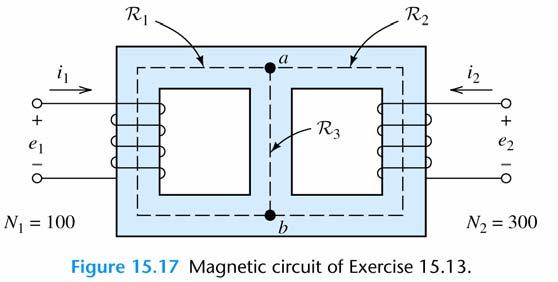
17 A Magnetic Circuit with Reluctances in Series and Parallel 17

18 INDUCTANCE AND MUTUAL INDUCTANCE L = λ i L = N R 2 e = L di dt 18

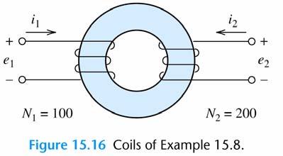
19 Mutual Inductance L 1 = λ i 11 1 L 2 = λ i 22 2 M = λ 21 = i 1 λ i

20 Dot Convention Aiding fluxes are produced by currents entering like marked terminals. Circuit Equations for Mutual Inductance λ1 = L1i 1 ± Mi2 λ2 = ± Mi1 + L2i2 dλ1 di1 di2 e1 = = L1 ± M dt dt dt dλ2 di1 di e2 = = ± M + L2 dt dt dt 2 20
21 21

22 MAGNETIC MATERIALS The relationship between B and H is not linear for the types of iron used in motors and transformers. 22
23 Energy Considerations W v = W Al = B 0 H db 23

24 Core Loss Power loss due to hysteresis is proportional to frequency, assuming constant peak flux. 24
25 Eddy-Current Loss Power loss due to eddy currents is proportional to the square of frequency, assuming constant peak flux. 25
26 Energy Stored in the Magnetic Field W B = 0 2 B B db µ 2µ v = 26
 p ( t) p2 = 1")
27 IDEAL TRANSFORMERS N N 2 () t v () t v2 = 1 1 I = N 1 2rms I1rms N 2 ( t) p ( t) p2 = 1 27
28 Transformer Summary 1. We assumed that all of the flux links all of the windings of both coils and that the resistance of the coils is zero. Thus, the voltage across each coil is proportional to the number of turns on the coil. N N 2 () t v () t v2 =
29 2. We assumed that the reluctance of the core is negligible, so the total mmf of both coils is N N zero. () 1 t i () t i2 = A consequence of the voltage and current relationships is that all of the power delivered to an ideal transformer by the source is transferred to the load. 29
30 Analysis of a Circuit Containing an Ideal Transformer 30
31 31 Impedance Transformations L Z L N N Z = = I V
32 32
33 REAL TRANSFORMERS 33

34 Variations of the Transformer Model 34
35 Regulation and Efficiency V percent regulation = V no -load load V load 100% power efficiency Pload Ploss = 100% = 1 100% Pin P in 35
Magnetism & Electromagnetism
 Magnetism & Electromagnetism By: Dr Rosemizi Abd Rahim Click here to watch the magnetism and electromagnetism animation video http://rmz4567.blogspot.my/2013/02/electrical-engineering.html 1 Learning Outcomes
Chapter 1 Magnetic Circuits
 Principles of Electric Machines and Power Electronics Third Edition P. C. Sen Chapter 1 Magnetic Circuits Chapter 1: Main contents i-h relation, B-H relation Magnetic circuit and analysis Property of magnetic
R. W. Erickson. Department of Electrical, Computer, and Energy Engineering University of Colorado, Boulder
 R. W. Erickson Department of Electrical, Computer, and Energy Engineering University of Colorado, Boulder Part III. Magnetics 13 Basic Magnetics Theory 14 Inductor Design 15 Transformer Design 1 Chapter
The initial magnetization curve shows the magnetic flux density that would result when an increasing magnetic field is applied to an initially
 MAGNETIC CIRCUITS The study of magnetic circuits is important in the study of energy systems since the operation of key components such as transformers and rotating machines (DC machines, induction machines,
MAGNETIC CIRCUITS. Magnetic Circuits
 Basic Electrical Theory What is a magnetic circuit? To better understand magnetic circuits, a basic understanding of the physical qualities of magnetic circuits will be necessary. EO 1.8 EO 1.9 EO 1.10
Lecture Notes ELEC A6
 Lecture Notes ELEC A6 Dr. Ramadan El-Shatshat Magnetic circuit 9/27/2006 Elec-A6 - Electromagnetic Energy Conversion 1 Magnetic Field Concepts Magnetic Fields: Magnetic fields are the fundamental mechanism
iclicker: which statements are correct?
 iclicker: which statements are correct? 1. Electric field lines must originate and terminate on charges 2. Magnetic field lines are always closed A: 1&2 B: only 1 C: only 2 D: neither 2 Inductive E-field:
Review of Basic Electrical and Magnetic Circuit Concepts EE
 Review of Basic Electrical and Magnetic Circuit Concepts EE 442-642 Sinusoidal Linear Circuits: Instantaneous voltage, current and power, rms values Average (real) power, reactive power, apparent power,
Lecture 24. April 5 th, Magnetic Circuits & Inductance
 Lecture 24 April 5 th, 2005 Magnetic Circuits & Inductance Reading: Boylestad s Circuit Analysis, 3 rd Canadian Edition Chapter 11.1-11.5, Pages 331-338 Chapter 12.1-12.4, Pages 341-349 Chapter 12.7-12.9,
An Introduction to Electrical Machines. P. Di Barba, University of Pavia, Italy
 An Introduction to Electrical Machines P. Di Barba, University of Pavia, Italy Academic year 0-0 Contents Transformer. An overview of the device. Principle of operation of a single-phase transformer 3.
Switched Mode Power Conversion
 Inductors Devices for Efficient Power Conversion Switches Inductors Transformers Capacitors Inductors Inductors Store Energy Inductors Store Energy in a Magnetic Field In Power Converters Energy Storage
Chapter 23 Magnetic Flux and Faraday s Law of Induction
 Chapter 23 Magnetic Flux and Faraday s Law of Induction 1 Overview of Chapter 23 Induced Electromotive Force Magnetic Flux Faraday s Law of Induction Lenz s Law Mechanical Work and Electrical Energy Generators
Magnetic Quantities. Magnetic fields are described by drawing flux lines that represent the magnetic field.
 Chapter 7 Magnetic fields are described by drawing flux lines that represent the magnetic field. Where lines are close together, the flux density is higher. Where lines are further apart, the flux density
Electromagnetism. Topics Covered in Chapter 14:
 Chapter 14 Electromagnetism Topics Covered in Chapter 14: 14-1: Ampere-turns of Magnetomotive Force (mmf) 14-2: Field Intensity (H) 14-3: B-H Magnetization Curve 14-4: Magnetic Hysteresis 14-5: Magnetic
Magnetic Fields
 Magnetic circuits introduction Becomes aware of the similarities between the analysis of magnetic circuits and electric circuits. Develop a clear understanding of the important parameters of a magnetic
Electromagnetic Induction & Inductors
 Electromagnetic Induction & Inductors 1 Revision of Electromagnetic Induction and Inductors (Much of this material has come from Electrical & Electronic Principles & Technology by John Bird) Magnetic Field
Tutorial Sheet Fig. Q1
 Tutorial Sheet - 04 1. The magnetic circuit shown in Fig. Q1 has dimensions A c = A g = 9 cm 2, g = 0.050 cm, l c = 30 cm, and N = 500 turns. Assume the value of the relative permeability,µ r = 70,000
ROEVER COLLEGE OF ENGINEERING & TECHNOLOGY ELAMBALUR, PERAMBALUR DEPARTMENT OF ELECTRICAL AND ELECTRONICS ENGINEERING ELECTRICAL MACHINES I
 ROEVER COLLEGE OF ENGINEERING & TECHNOLOGY ELAMBALUR, PERAMBALUR-621220 DEPARTMENT OF ELECTRICAL AND ELECTRONICS ENGINEERING ELECTRICAL MACHINES I Unit I Introduction 1. What are the three basic types
Definition Application of electrical machines Electromagnetism: review Analogies between electric and magnetic circuits Faraday s Law Electromagnetic
 Definition Application of electrical machines Electromagnetism: review Analogies between electric and magnetic circuits Faraday s Law Electromagnetic Force Motor action Generator action Types and parts
Revision Guide for Chapter 15
 Revision Guide for Chapter 15 Contents Revision Checklist Revision otes Transformer...4 Electromagnetic induction...4 Lenz's law...5 Generator...6 Electric motor...7 Magnetic field...9 Magnetic flux...
ENGINEERING COUNCIL CERTIFICATE LEVEL ENGINEERING SCIENCE C103 TUTORIAL 16 - INDUCTANCE
 ENGINEERING COUNCIL CERTIFICATE LEVEL ENGINEERING SCIENCE C103 TUTORIAL 16 - INDUCTANCE On completion of this tutorial you should be able to do the following. Explain inductance and inductors. Explain
Lecture 33. PHYC 161 Fall 2016
 Lecture 33 PHYC 161 Fall 2016 Faraday s law of induction When the magnetic flux through a single closed loop changes with time, there is an induced emf that can drive a current around the loop: Recall
Part 4: Electromagnetism. 4.1: Induction. A. Faraday's Law. The magnetic flux through a loop of wire is
 1 Part 4: Electromagnetism 4.1: Induction A. Faraday's Law The magnetic flux through a loop of wire is Φ = BA cos θ B A B = magnetic field penetrating loop [T] A = area of loop [m 2 ] = angle between field
Chapter 7. Chapter 7. Electric Circuits Fundamentals - Floyd. Copyright 2007 Prentice-Hall
 Chapter 7 Magnetic Quantities Magnetic fields are described by drawing flux lines that represent the magnetic field. Where lines are close together, the flux density is higher. Where lines are further
Switched Mode Power Conversion Prof. L. Umanand Department of Electronics System Engineering Indian Institute of Science, Bangalore
 Switched Mode Power Conversion Prof. L. Umanand Department of Electronics System Engineering Indian Institute of Science, Bangalore Lecture - 39 Magnetic Design Good day to all of you. Today, we shall
Physics Notes for Class 12 chapter 6 ELECTROMAGNETIC I NDUCTION
 1 P a g e Physics Notes for Class 12 chapter 6 ELECTROMAGNETIC I NDUCTION Whenever the magnetic flux linked with an electric circuit changes, an emf is induced in the circuit. This phenomenon is called
Part III. Magnetics. Chapter 13: Basic Magnetics Theory. Chapter 13 Basic Magnetics Theory
 Part III. Magnetics 3 Basic Magnetics Theory Inductor Design 5 Transformer Design Chapter 3 Basic Magnetics Theory 3. Review of Basic Magnetics 3.. Basic relationships 3..2 Magnetic circuits 3.2 Transformer
EDEXCEL NATIONAL CERTIFICATE/DIPLOMA UNIT 5 - ELECTRICAL AND ELECTRONIC PRINCIPLES NQF LEVEL 3. OUTCOME 3 - MAGNETISM and INDUCTION
 EDEXCEL NATIONAL CERTIFICATE/DIPLOMA UNIT 5 - ELECTRICAL AND ELECTRONIC PRINCIPLES NQF LEVEL 3 OUTCOME 3 - MAGNETISM and INDUCTION 3 Understand the principles and properties of magnetism Magnetic field:
ELECTRICALMACHINES-I QUESTUION BANK
 ELECTRICALMACHINES-I QUESTUION BANK UNIT-I INTRODUCTION OF MAGNETIC MATERIAL PART A 1. What are the three basic rotating Electric machines? 2. Name the three materials used in machine manufacture. 3. What
DO PHYSICS ONLINE MOTORS AND GENERATORS FARADAY S LAW ELECTROMAGNETIC INDUCTION
 DO PHYSICS ONLINE MOTORS AND GENERATORS FARADAY S LAW ELECTROMAGNETIC INDUCTION English Michael Faraday (1791 1867) who experimented with electric and magnetic phenomena discovered that a changing magnetic
SYLLABUS(EE-205-F) SECTION-B
 SECTION-B") SYLLABUS(EE-205-F) SECTION-A MAGNETIC CIRCUITS AND INDUCTION: Magnetic Circuits, Magnetic Materials and their properties, static and dynamic emfs and dforce on current carrying conductor, AC operation
SYLLABUS(EE-205-F) SECTION-A MAGNETIC CIRCUITS AND INDUCTION: Magnetic Circuits, Magnetic Materials and their properties, static and dynamic emfs and dforce on current carrying conductor, AC operation
Transformer Fundamentals
 Transformer Fundamentals 1 Introduction The physical basis of the transformer is mutual induction between two circuits linked by a common magnetic field. Transformer is required to pass electrical energy
Transformer. Transformer comprises two or more windings coupled by a common magnetic circuit (M.C.).
.") . Transformers Transformer Transformer comprises two or more windings coupled by a common magnetic circuit (M.C.). f the primary side is connected to an AC voltage source v (t), an AC flux (t) will be
. Transformers Transformer Transformer comprises two or more windings coupled by a common magnetic circuit (M.C.). f the primary side is connected to an AC voltage source v (t), an AC flux (t) will be
Chapter 2 Basics of Electricity and Magnetism
 Chapter 2 Basics of Electricity and Magnetism My direct path to the special theory of relativity was mainly determined by the conviction that the electromotive force induced in a conductor moving in a
Notes on Mutual Inductance and Transformers J. McCalley
 ωωωωωωωω ωωωωωωωω otes on Mutual nductance and Transformers J. McCalley.0 Use of Transformers Transformers are one of the most common electrical devices. Perhaps the most familiar application today is
Chapter 27, 28 & 29: Magnetism & Electromagnetic Induction. Magnetic flux Faraday s and Lenz s law Electromagnetic Induction Ampere s law
 Chapter 27, 28 & 29: Magnetism & Electromagnetic Induction Magnetic flux Faraday s and Lenz s law Electromagnetic Induction Ampere s law 1 Magnetic Flux and Faraday s Law of Electromagnetic Induction We
Practical Transformer
 Practical Transformer φ c i P tructure and dot convention ymbol and polarity Dot convention: the primary and secondary currents flowing into the winding terminals marked produce a mutually additive magnetic
Mutual Inductance: This is the magnetic flux coupling of 2 coils where the current in one coil causes a voltage to be induced in the other coil.
 agnetically Coupled Circuits utual Inductance: This is the magnetic flux coupling of coils where the current in one coil causes a voltage to be induced in the other coil. st I d like to emphasize that
DHANALAKSHMI SRINIVASAN INSTITUTE OF RESEARCH AND TECHNOLOGY
 DHANALAKSHMI SRINIVASAN INSTITUTE OF RESEARCH AND TECHNOLOGY SIRUVACHUR-621113 ELECTRICAL AND ELECTRONICS DEPARTMENT 2 MARK QUESTIONS AND ANSWERS SUBJECT CODE: EE 6302 SUBJECT NAME: ELECTROMAGNETIC THEORY
Induction_P1. 1. [1 mark]
![Induction_P1. 1. [1 mark]](/thumbs/88/115570773.jpg "Induction_P1. 1. [1 mark]") Induction_P1 1. [1 mark] Two identical circular coils are placed one below the other so that their planes are both horizontal. The top coil is connected to a cell and a switch. The switch is closed and
Induction_P1 1. [1 mark] Two identical circular coils are placed one below the other so that their planes are both horizontal. The top coil is connected to a cell and a switch. The switch is closed and
Basic Electrical Technology Prof. Dr. L. Umanand Department of Electrical Engineering Indian Institute of Science, Bangalore
 Basic Electrical Technology Prof. Dr. L. Umanand Department of Electrical Engineering Indian Institute of Science, Bangalore Lecture - 18 Transformer Basics Part - II Hello everybody, in the last session
Chapter 2: Fundamentals of Magnetism. 8/28/2003 Electromechanical Dynamics 1
 Chapter 2: Fundamentals of Magnetism 8/28/2003 Electromechanical Dynamics 1 Magnetic Field Intensity Whenever a magnetic flux, φ, exist in a conductor or component, it is due to the presence of a magnetic
Chapter 30. Induction and Inductance
 Chapter 30 Induction and Inductance 30.2: First Experiment: 1. A current appears only if there is relative motion between the loop and the magnet (one must move relative to the other); the current disappears
CURRENT-CARRYING CONDUCTORS / MOVING CHARGES / CHARGED PARTICLES IN CIRCULAR ORBITS
 PHYSICS A2 UNIT 4 SECTION 4: MAGNETIC FIELDS CURRENT-CARRYING CONDUCTORS / MOVING CHARGES / CHARGED PARTICLES IN CIRCULAR ORBITS # Questions MAGNETIC FLUX DENSITY 1 What is a magnetic field? A region in
Revision Guide for Chapter 15
 Revision Guide for Chapter 15 Contents tudent s Checklist Revision otes Transformer... 4 Electromagnetic induction... 4 Generator... 5 Electric motor... 6 Magnetic field... 8 Magnetic flux... 9 Force on
Electrical Machines I Week 3: Energy Storage
 Electrical Machines Week 3: Energy Storage RECALL REMEMBER.!! Magnetic circuits and electrical circuits are co-related ngredients What is hystresis Magnetic Losses?? WHY DO WE NEED ALL OF THS ANYWAY!!!!
Lecture 12. Time Varying Electromagnetic Fields
 Lecture. Time Varying Electromagnetic Fields For static electric and magnetic fields: D = ρ () E = 0...( ) D= εe B = 0...( 3) H = J H = B µ...( 4 ) For a conducting medium J =σ E From Faraday s observations,
COLLEGE PHYSICS Chapter 23 ELECTROMAGNETIC INDUCTION, AC CIRCUITS, AND ELECTRICAL TECHNOLOGIES
 COLLEGE PHYSICS Chapter 23 ELECTROMAGNETIC INDUCTION, AC CIRCUITS, AND ELECTRICAL TECHNOLOGIES Induced emf: Faraday s Law and Lenz s Law We observe that, when a magnet is moved near a conducting loop,
PHYSICS - GIANCOLI CALC 4E CH 29: ELECTROMAGNETIC INDUCTION.
 !! www.clutchprep.com CONCEPT: ELECTROMAGNETIC INDUCTION A coil of wire with a VOLTAGE across each end will have a current in it - Wire doesn t HAVE to have voltage source, voltage can be INDUCED i V Common
LECTURE 5 PER-PHASE CIRCUITS AND MAGNETICS (1)
") ECE 330 POWER CIRCUITS AND ELECTROMECHANICS LECTURE 5 PER-PHASE CIRCUITS AND MAGNETICS (1) Aknowledgment-These handouts and leture notes given in lass are based on material from Prof. Peter Sauer s ECE
ECE 330 POWER CIRCUITS AND ELECTROMECHANICS LECTURE 5 PER-PHASE CIRCUITS AND MAGNETICS (1) Aknowledgment-These handouts and leture notes given in lass are based on material from Prof. Peter Sauer s ECE
Chapter 23 Magnetic Flux and Faraday s Law of Induction
 Chapter 23 Magnetic Flux and Faraday s Law of Induction Recall: right hand rule 2 10/28/2013 Units of Chapter 23 Induced Electromotive Force Magnetic Flux Faraday s Law of Induction Lenz s Law Mechanical
Prof. Krishna Vasudevan, Prof. G. Sridhara Rao, Prof. P. Sasidhara Rao
 2 Basic Principles As mentioned earlier the transformer is a static device working on the principle of Faraday s law of induction. Faraday s law states that a voltage appears across the terminals of an
Physics / Higher Physics 1A. Electricity and Magnetism Revision
 Physics / Higher Physics 1A Electricity and Magnetism Revision Electric Charges Two kinds of electric charges Called positive and negative Like charges repel Unlike charges attract Coulomb s Law In vector
Physics 182. Assignment 4
 Physics 182 Assignment 4 1. A dipole (electric or magnetic) in a non-uniform field will in general experience a net force. The electric case was the subject of a problem on the midterm exam; here we examine
Magnets. Domain = small magnetized region of a magnetic material. all the atoms are grouped together and aligned
 Magnetic Fields Magnets Domain = small magnetized region of a magnetic material all the atoms are grouped together and aligned Magnets Ferromagnetic materials domains can be forced to line up by applying
Handout 8: Sources of magnetic field. Magnetic field of moving charge
 1 Handout 8: Sources of magnetic field Magnetic field of moving charge Moving charge creates magnetic field around it. In Fig. 1, charge q is moving at constant velocity v. The magnetic field at point
1. An isolated stationary point charge produces around it. a) An electric field only. b) A magnetic field only. c) Electric as well magnetic fields.
 An electric field only. b) A magnetic field only. c) Electric as well magnetic fields.") 1. An isolated stationary point charge produces around it. a) An electric field only. b) A magnetic field only. c) Electric as well magnetic fields. 2. An isolated moving point charge produces around it.
1. An isolated stationary point charge produces around it. a) An electric field only. b) A magnetic field only. c) Electric as well magnetic fields. 2. An isolated moving point charge produces around it.
ELECTROMAGNETIC INDUCTION AND FARADAY S LAW
 ELECTROMAGNETIC INDUCTION AND FARADAY S LAW Magnetic Flux The emf is actually induced by a change in the quantity called the magnetic flux rather than simply py by a change in the magnetic field Magnetic
Recap (1) Maxwell s Equations describe the electric field E and magnetic field B generated by stationary charge density ρ and current density J:
 Maxwell s Equations describe the electric field E and magnetic field B generated by stationary charge density ρ and current density J:") Class 13 : Induction Phenomenon of induction and Faraday s Law How does a generator and transformer work? Self- and mutual inductance Energy stored in B-field Recap (1) Maxwell s Equations describe the
Class 13 : Induction Phenomenon of induction and Faraday s Law How does a generator and transformer work? Self- and mutual inductance Energy stored in B-field Recap (1) Maxwell s Equations describe the
ELECTROMAGNETIC INDUCTION
 ELECTROMAGNETIC INDUCTION 1. Magnetic Flux 2. Faraday s Experiments 3. Faraday s Laws of Electromagnetic Induction 4. Lenz s Law and Law of Conservation of Energy 5. Expression for Induced emf based on
Magnetic field creation (example of a problem)
") 1 Magnetic field creation (example of a problem) Three long, straight wires are parallel to each other and perpendicular to the plane of the paper. Their mutual location is shown in Figure below. The currents
1 Magnetic field creation (example of a problem) Three long, straight wires are parallel to each other and perpendicular to the plane of the paper. Their mutual location is shown in Figure below. The currents
Handout 10: Inductance. Self-Inductance and inductors
 1 Handout 10: Inductance Self-Inductance and inductors In Fig. 1, electric current is present in an isolate circuit, setting up magnetic field that causes a magnetic flux through the circuit itself. This
Lecture Set 1 Introduction to Magnetic Circuits
 Lecture Set 1 Introduction to Magnetic Circuits S.D. Sudhoff Spring 2017 1 Goals Review physical laws pertaining to analysis of magnetic systems Introduce concept of magnetic circuit as means to obtain
magneticsp17 September 14, of 17
 EXPERIMENT Magnetics Faraday s Law in Coils with Permanent Magnet, DC and AC Excitation OBJECTIVE The knowledge and understanding of the behavior of magnetic materials is of prime importance for the design
DHANALAKSHMI COLLEGE OF ENGINEERING DEPARTMENT OF EEE PART A. 1. Define mutual inductance and self inductance. (A/M-15)
") DHANALAKSHMI COLLEGE OF ENGINEERING DEPARTMENT OF EEE EE6302-ELECTROMAGNETIC THEORY UNIT 4 PART A 1. Define mutual inductance and self inductance. (A/M-15) Self inductance is the ration between the induced
DHANALAKSHMI COLLEGE OF ENGINEERING DEPARTMENT OF EEE EE6302-ELECTROMAGNETIC THEORY UNIT 4 PART A 1. Define mutual inductance and self inductance. (A/M-15) Self inductance is the ration between the induced
Get Discount Coupons for your Coaching institute and FREE Study Material at ELECTROMAGNETIC INDUCTION
 ELECTROMAGNETIC INDUCTION 1. Magnetic Flux 2. Faraday s Experiments 3. Faraday s Laws of Electromagnetic Induction 4. Lenz s Law and Law of Conservation of Energy 5. Expression for Induced emf based on
SECOND ENGINEER REG III/2 MARINE ELECTRO-TECHNOLOGY. 1. Understands the physical construction and characteristics of basic components.
 SECOND ENGINEER REG III/ MARINE ELECTRO-TECHNOLOGY LIST OF TOPICS A B C D Electric and Electronic Components Electric Circuit Principles Electromagnetism Electrical Machines The expected learning outcome
Magnetic Force on a Moving Charge
 Magnetic Force on a Moving Charge Electric charges moving in a magnetic field experience a force due to the magnetic field. Given a charge Q moving with velocity u in a magnetic flux density B, the vector
/20 /20 /20 /60. Dr. Galeazzi PHY207 Test #3 November 20, I.D. number:
 Signature: Name: I.D. number: You must do ALL the problems Each problem is worth 0 points for a total of 60 points. TO GET CREDIT IN PROBLEMS AND 3 YOU MUST SHOW GOOD WORK. CHECK DISCUSSION SECTION ATTENDED:
Electromagnetics in Medical Physics
 Electromagnetics in Medical Physics Part 4. Biomagnetism Tong In Oh Department of Biomedical Engineering Impedance Imaging Research Center (IIRC) Kyung Hee University Korea tioh@khu.ac.kr Dot Product (Scalar
SUMMARY Phys 2523 (University Physics II) Compiled by Prof. Erickson. F e (r )=q E(r ) dq r 2 ˆr = k e E = V. V (r )=k e r = k q i. r i r.
 Compiled by Prof. Erickson. F e (r )=q E(r ) dq r 2 ˆr = k e E = V. V (r )=k e r = k q i. r i r.") SUMMARY Phys 53 (University Physics II) Compiled by Prof. Erickson q 1 q Coulomb s Law: F 1 = k e r ˆr where k e = 1 4π =8.9875 10 9 N m /C, and =8.85 10 1 C /(N m )isthepermittivity of free space. Generally,
SUMMARY Phys 53 (University Physics II) Compiled by Prof. Erickson q 1 q Coulomb s Law: F 1 = k e r ˆr where k e = 1 4π =8.9875 10 9 N m /C, and =8.85 10 1 C /(N m )isthepermittivity of free space. Generally,
LECTURE 6 MUTUAL INDUCTANCE
 ECE 330 POWER CIRCUITS AND ELECTROMECHANICS LECTURE 6 MUTUAL INDUCTANCE Acknowledgment-These handouts and lecture notes given in class are based on material from Prof. Peter Sauer s ECE 330 lecture notes.
Suppose two uniform bars meet at an abrupt plane and there is a magnetic field induced by an extended core and coil structure off stage as in:
 Class Notes Week of 1/9 /3/017 ENGN1931F The magnetic structures that are central to the design of generators, transformers, motors, inductors, solenoids, etc. can be complex. We need a way to make approximate
RLC Circuit (3) We can then write the differential equation for charge on the capacitor. The solution of this differential equation is
 We can then write the differential equation for charge on the capacitor. The solution of this differential equation is") RLC Circuit (3) We can then write the differential equation for charge on the capacitor The solution of this differential equation is (damped harmonic oscillation!), where 25 RLC Circuit (4) If we charge
RLC Circuit (3) We can then write the differential equation for charge on the capacitor The solution of this differential equation is (damped harmonic oscillation!), where 25 RLC Circuit (4) If we charge
Self-Inductance. Φ i. Self-induction. = (if flux Φ 1 through 1 loop. Tm Vs A A. Lecture 11-1
 Lecture - Self-Inductance As current i through coil increases, magnetic flux through itself increases. This in turn induces back emf in the coil itself When current i is decreasing, emf is induced again
David J. Starling Penn State Hazleton PHYS 212
 and and The term inductance was coined by Oliver Heaviside in February 1886. David J. Starling Penn State Hazleton PHYS 212 and We have seen electric flux: Φ E = E d A But we can define the magnetic flux
ME1633: Integration of Physics, Motion and Metrology
 ME1633: Integration of Physics, Motion and Metrology Assignment 4: Magnetism solutions 22 November 2013 You can do this assignment on your own or in groups, as long as you hand in your own solutions and
Induction. Chapter 29. PowerPoint Lectures for University Physics, Twelfth Edition Hugh D. Young and Roger A. Freedman. Lectures by James Pazun
 Chapter 29 Electromagnetic Induction PowerPoint Lectures for University Physics, Twelfth Edition Hugh D. Young and Roger A. Freedman Lectures by James Pazun 29. Electromagnetic induction 1. Magnetic flux/faraday
Sliding Conducting Bar
 Motional emf, final For equilibrium, qe = qvb or E = vb A potential difference is maintained between the ends of the conductor as long as the conductor continues to move through the uniform magnetic field
Chapter 21 Magnetic Induction Lecture 12
 Chapter 21 Magnetic Induction Lecture 12 21.1 Why is it called Electromagnetism? 21.2 Magnetic Flux and Faraday s Law 21.3 Lenz s Law and Work-Energy Principles 21.4 Inductance 21.5 RL Circuits 21.6 Energy
FXA 2008 Φ = BA. Candidates should be able to : Define magnetic flux. Define the weber (Wb). Select and use the equation for magnetic flux :
. Select and use the equation for magnetic flux :") 1 Candidates should be able to : Define magnetic flux. Define the weber (Wb). Select and use the equation for magnetic flux : Φ = BAcosθ MAGNETIC FLUX (Φ) As we have already stated, a magnetic field is
1 Candidates should be able to : Define magnetic flux. Define the weber (Wb). Select and use the equation for magnetic flux : Φ = BAcosθ MAGNETIC FLUX (Φ) As we have already stated, a magnetic field is
Tutorial Sheet IV. Fig. IV_2.
 Tutorial Sheet IV 1. Two identical inductors 1 H each are connected in series as shown. Deduce the combined inductance. If a third and then a fourth are similarly connected in series with this combined
Inductance. thevectorpotentialforthemagneticfield, B 1. ] d l 2. 4π I 1. φ 12 M 12 I 1. 1 Definition of Inductance. r 12
![Inductance. thevectorpotentialforthemagneticfield, B 1. ] d l 2. 4π I 1. φ 12 M 12 I 1. 1 Definition of Inductance. r 12](/thumbs/72/67161747.jpg "Inductance. thevectorpotentialforthemagneticfield, B 1. ] d l 2. 4π I 1. φ 12 M 12 I 1. 1 Definition of Inductance. r 12") Inductance 1 Definition of Inductance When electric potentials are placed on a system of conductors, charges move to cancel the electric field parallel to the conducting surfaces of the conductors. We
Inductance 1 Definition of Inductance When electric potentials are placed on a system of conductors, charges move to cancel the electric field parallel to the conducting surfaces of the conductors. We
MAGNETIC CIRCUITS, MOTOR AND GENERATOR ACTION
 Topic 3 MAGNETIC CIRCUITS, MOTOR AND GENERATOR ACTION Magnetic Flux SI unit, Webers (Wb) ϕ Flows from North to South Pole 1 Magnetic Flux Density Measure of Flux/Area SI units, Wb/m 2 = Tesla, B Think
Chapter 30 Inductance
 Chapter 30 Inductance In this chapter we investigate the properties of an inductor in a circuit. There are two kinds of inductance mutual inductance and self-inductance. An inductor is formed by taken
Assessment Schedule 2015 Physics: Demonstrate understanding of electrical systems (91526)
") NCEA Level 3 Physics (91526) 2015 page 1 of 6 Assessment Schedule 2015 Physics: Demonstrate understanding of electrical systems (91526) Evidence Q Evidence Achievement Achievement with Merit Achievement
NCEA Level 3 Physics (91526) 2015 page 1 of 6 Assessment Schedule 2015 Physics: Demonstrate understanding of electrical systems (91526) Evidence Q Evidence Achievement Achievement with Merit Achievement
CHAPTER 8 DC MACHINERY FUNDAMENTALS
 CHAPTER 8 DC MACHINERY FUNDAMENTALS Summary: 1. A Simple Rotating Loop between Curved Pole Faces - The Voltage Induced in a Rotating Loop - Getting DC voltage out of the Rotating Loop - The Induced Torque
CHAPTER 6. Inductance, Capacitance, and Mutual Inductance
 CHAPTER 6 Inductance, Capacitance, and Mutual Inductance 6.1 The Inductor Inductance is symbolized by the letter L, is measured in henrys (H), and is represented graphically as a coiled wire. The inductor
Application Of Faraday s Law
 Application Of Faraday s Law Dr Miguel Cavero September 2, 2014 Application Of Faraday s Law September 2, 2014 1 / 23 The PHYS120 Exam will be divided into three sections as follows: Section A: Short Questions
n Higher Physics 1B (Special) (PHYS1241) (6UOC) n Advanced Science n Double Degree (Science/Engineering) n Credit or higher in Physics 1A
 (PHYS1241) (6UOC) n Advanced Science n Double Degree (Science/Engineering) n Credit or higher in Physics 1A") Physics in Session 2: I n Physics / Higher Physics 1B (PHYS1221/1231) n Science, dvanced Science n Engineering: Electrical, Photovoltaic,Telecom n Double Degree: Science/Engineering n 6 UOC n Waves n Physical
Physics in Session 2: I n Physics / Higher Physics 1B (PHYS1221/1231) n Science, dvanced Science n Engineering: Electrical, Photovoltaic,Telecom n Double Degree: Science/Engineering n 6 UOC n Waves n Physical
Chapter 5: Electromagnetic Induction
 Chapter 5: Electromagnetic Induction 5.1 Magnetic Flux 5.1.1 Define and use magnetic flux Magnetic flux is defined as the scalar product between the magnetic flux density, B with the vector of the area,
Chapter 30. Induction and Inductance
 Chapter 30 Induction and Inductance 30.2: First Experiment: 1. A current appears only if there is relative motion between the loop and the magnet (one must move relative to the other); the current disappears
Electromagnetic Induction
 Chapter II Electromagnetic Induction Day 1 Induced EMF, Faraday s Law and Lenz s Law Sections 21-1 to 21-2 Electromotive Force Electromotive force (EMF ore) is a misnomer, as it is not really a force but
6.013 Lecture 11: Inductors and Transformers
 6.013 Lecture 11: Inductors and Transformers A. Inductors All circuits carry currents that necessarily produce magnetic fields and store magnetic energy. Thus every wire and circuit element generally has
Experiment 5: Measurements Magnetic Fields
 Experiment 5: Measurements Magnetic Fields Introduction In this laboratory you will use fundamental electromagnetic Equations and principles to measure the magnetic fields of two magnets. 1 Physics 1.1
PHYS 1441 Section 001 Lecture #23 Monday, Dec. 4, 2017
 PHYS 1441 Section 1 Lecture #3 Monday, Dec. 4, 17 Chapter 3: Inductance Mutual and Self Inductance Energy Stored in Magnetic Field Alternating Current and AC Circuits AC Circuit W/ LRC Chapter 31: Maxwell
PHY 131 Review Session Fall 2015 PART 1:
 PHY 131 Review Session Fall 2015 PART 1: 1. Consider the electric field from a point charge. As you move farther away from the point charge, the electric field decreases at a rate of 1/r 2 with r being
Lecture 16.1 :! Final Exam Review, Part 2
 Lecture 16.1 :! Final Exam Review, Part 2 April 28, 2015 1 Announcements Online Evaluation e-mails should have been sent to you.! Please fill out the evaluation form. May 6 is deadline.! Remember that
Introduction to Electromagnetism
 Introduction to Electromagnetism Electric Field Lines If a charge feels an electrostatic force (Coulombic Force), it is said to be in an electric field. We like to represent electric fields with lines.
Outside the solenoid, the field lines are spread apart, and at any given distance from the axis, the field is weak.
 Applications of Ampere s Law continued. 2. Field of a solenoid. A solenoid can have many (thousands) of turns, and perhaps many layers of windings. The figure shows a simple solenoid with just a few windings