Some Important Electrical Units
|
|
|
- Zoe Fletcher
- 5 years ago
- Views:
Transcription

1 Some Important Electrical Units Quantity Unit Symbol Current Charge Voltage Resistance Power Ampere Coulomb Volt Ohm Watt A C V W W These derived units are based on fundamental units from the meterkilogram-second system, hence are called mks units. Except for current, all electrical and magnetic units are derived from the fundamental units. SI Fundamental Units Current is a fundamental unit.


2 Unit Symbols Metric Prefixes
3 Error, Accuracy, and Precision Experimental uncertainty is part of all measurements. Error is the difference between the true or best accepted value and the measured value. Accuracy ( 정확도 ) is an indication of the range of error in a measurement. Precision ( 정밀도 ) is a measure of repeatability or consistency. } Error Precise, but not accurate. 교정 (correction) 이필요함 Tolerance ( 허용오차 ) ~ 1 %, 5 %, 10 %
4 Significant Digits ( 유효숫자 ) When reporting a measured value, one uncertain digit may be retained but other uncertain digits should be discarded. Normally this is the same number of digits as in the original measurement. 1. Nonzero digits are always considered to be significant. Example: has four nonzero digits they are all significant. 2. Zeros to the left of the first nonzero digit are never significant. Example: has three zeros to the left of the first nonzero digit. There are only three significant digits. 3. Zeros between nonzero digits are always significant. Example: 806 has three significant digits. 4. Zeros to the right of the decimal point for a decimal number are significant. Example: 9.00 has three significant digits. 5. Zeros to the left of the decimal point with a whole number may or may not be significant depending on the measurement. Example: 4000 does not have a clear number of significant digits.


5 Electrical Safety Safety is always a concern with electrical circuits. Knowing the rules and maintaining a safe environment is everyone s job. Do not work alone, or when you are drowsy. Do not wear conductive jewelry. Know the potential hazards of the equipment you are working on; check equipment and power cords frequently. Avoid all contact with energized circuits; even low voltage circuits. Maintain a clean workspace. Know the location of power shutoff and fire extinguishers. Don t have food or drinks in the laboratory or work area. ( 컴퓨터옆에둔커피잔은반드시엎어진다 ) Body resistance ~ 20 kw
.")

6 Current Current (I) is the amount of charge (Q) that flows past a point in a unit of time (t). The defining equation is: I Q t Current sources are not as common as voltage sources, but they are useful for production testing. The units shown here include current sources as well as measurement instruments.
 is the resistance if one ampere (1 A) is in a material")

7 Resistance Resistance is the opposition to current. One ohm (1 W) is the resistance if one ampere (1 A) is in a material when one volt (1 V) is applied. 1 l Conductance is the reciprocal of resistance. G R R A Components designed to have a specific amount of resistance are called resistors.
 Black Brown Red Orange Yellow Green Blue Violet Gray White 0 1 2 3 4 5 6 7 8 9 10 0 10 1 10 2 10 3 10 4 10 5 10 6 10 7 10 8 10 9 1% (five band) 2% (five band) 흑갈빨주노초파보회흰 Fourth band -")
8 Resistance color-code Color Digit Multiplier Tolerance Resistance value, first three bands: First band 1 st digit Second band 2 nd digit *Third band Multiplier (number of zeros following second digit) Black Brown Red Orange Yellow Green Blue Violet Gray White % (five band) 2% (five band) 흑갈빨주노초파보회흰 Fourth band - tolerance Gold Silver ±5% ± 10% % (four band) 10% (four band) No band ± 20% * For resistance values less than 10 W, the third band is either gold or silver. Gold is for a multiplier of 0.1 and silver is for a multiplier of kw ± 5% 47 W ± 10%


9 Alphanumeric Labeling Two or three digits, and one of the letters R, K, or M are used to identify a resistance value. The letter is used to indicate the multiplier, and its position is used to indicate decimal point position. Variable resistors include the potentiometer and rheostat. The center terminal of a variable resistor is connected to the wiper. R R Variable resistor (potentiometer) 분압기 Variable resistor (rheostat) 가감저항기
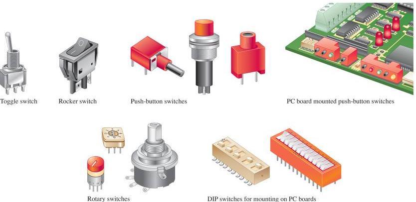
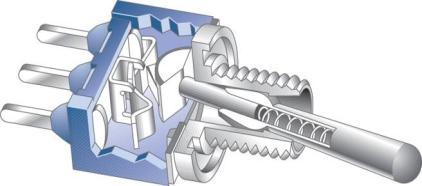
10 Switches
11 Voltage The defining equation for voltage is V W Q One volt is the potential difference (voltage) between two points when one joule of energy is used to move one coulomb of charge from one point to the other. Ideally, a voltage source can provide a constant voltage for any current required by a circuit. The IV curve for an ideal voltage source has a constant voltage for all current. In practice, ideal sources do not exist, but they can be closely approximated by actual sources.

12 A basic power supply


13 The DMM The DMM (Digital Multimeter) is an important multipurpose instrument which can measure voltage, current, and resistance. Many include other measurement options. Voltmeter connection to measure voltage in a simple circuit.


14 31 2-digit DMM illustrates how the resolution changes with the number of digits in use A typical analog multimeter
 formulated the equation that bears his name: If you need to solve for voltage, Ohm s law is: V IR If you need to solve for resistance, Ohm s law is: R V I I V R What is")
15 Ohm s law The most important fundamental law in electronics is Ohm s law, which relates voltage, current, and resistance. Georg Simon Ohm ( ) formulated the equation that bears his name: If you need to solve for voltage, Ohm s law is: V IR If you need to solve for resistance, Ohm s law is: R V I I V R What is the (hot) resistance of the bulb? 115 V OFF V Hz V mv 10 A A Range Autorange Touch/Hold 1 s 1 s V 40 ma COM Fused
16 Graph of Current versus Voltage Current (ma) Notice that the plot of current versus voltage for a fixed resistor is a line with a positive slope. What is the resistance indicated by the graph? 2.7 kw What is its conductance? 0.37 ms Voltage (V) + DC Ammeter - Power Supply Gnd 5 V 2A V A +15 V The resistor is green-blue brown-gold. What should the ammeter read? 초 - 파 - 갈 ~ 560 W 흑갈빨주노초파보
17 Energy and Power Energy is closely related to work. Energy is the ability to do work. It is measured in the same units as work, namely the newton-meter (N-m) or joule (J). What amount of energy is converted to heat in sliding a box along a floor for 5 meters if the force to move it is 400 N? W = Fd = (400 N)(5 m) = 2000 N-m = 2000 J Power is the rate of doing work. Because it is a rate, a time unit is required. The unit is the joule per second (J/s), which defines a watt (W). P W t What power is developed if the box in the previous example is moved in 10 s? W 2000 J P 200 W t 10 s

18 Electrical Energy and Power In electrical work, the rate energy is dissipated can be determined from any of three forms of the power formula. P 2 I R P VI P V R 2 Together, the three forms are called Watt s law. What power is dissipated in a 27 W resistor is the current is A? Given that you know the resistance and current, substitute the values into P =I 2 R. P 2 I R 2 (0.135 A) W W


19 Resistor failures Relative sizes of metal-film resistors with standard power ratings of 1 8 W, 1 4 W, 1 2 W, and 1 W. Typical resistors with high power ratings A triple output power supply
20 Series circuits A series circuit is one that has only one current path. If you break one of the resistors in series circuit, current does not flow at all. The current everywhere is the same, because there is only one path. The total resistance of resistors in series is the sum of the individual resistors.
21 Kirchhoff s voltage law The sum of all the voltage drops around a single closed path in a circuit is equal to the total source voltage in that closed path. KVL applies to all circuits, but you must apply it to only one closed path. In a series circuit, this is (of course) the entire circuit. A mathematical shorthand way of writing KVL is n i1 V i 0 V S Sum of n voltage drops equals the source voltage.

22 Voltage divider R 1 15 kw V S + R 2 20 V 10 kw What is the voltage across R 2? V R 10 kw V 20 V 25 kw 2 2 S RT 8.0 V Notice that 40% of the source voltage is across R 2, which represents 40% of the total resistance. V S + 15 V R 1 20 kw R 2 10 kw V OUT What is the largest output voltage available? 5.0 V Voltage dividers can be set up for a variable output using a potentiometer. In the circuit shown, the output voltage is variable.
23
24 Power in Series Circuits R W V S + R 2 20 V 330 W Use the voltage divider rule to find V 1 and V 2. Then find the power in R 1 and R 2 and P T. Applying the voltage divider rule: V W 20 V W V W 20 V W The power dissipated by each resistor is: P V W P V W P T = P 1 + P 2
. V B means the voltage at point B with respect to ground.")
25 Voltage measurements Voltage is relative and is measured with respect to another point in the circuit. V S + 12 V A R kw B R 2 10 kw C For example, V A means the voltage at point A with respect to ground (called reference ground). V B means the voltage at point B with respect to ground. V AB means the voltage between points A and B. Q1. What are V A, V B, and V AB for the circuit shown? V A = 12 V V B = 8 V V AB = 4 V V S + 12 V A R kw B R 2 10 kw C Q2. What are V A, V B, and V C for the circuit? V A = 4 V V B = 0 V V C = -8 V Q3. Has V AB changed from the previous circuit?

 connected to a")
26 Resistors in parallel Resistors that are connected to the same two points are said to be in parallel. ( 병렬저항 ) A parallel circuit is identified by the fact that it has more than one current path (branch) connected to a common voltage source.
27 Voltage across parallel branches is the same
28 Parallel circuit rules Because all components are connected across the same voltage source, the voltage across each is the same V V V V + - V S R 1 R 2 R V 680 W 1.5 kw 2.2 kw The total resistance of resistors in parallel is the reciprocal of the sum of the reciprocals of the individual resistors. RT R 1 R R R 1 2 or R T RR 1 2 R R 1 2
29 Connecting resistors in parallel reduces total resistance and increases total current. Circuit with n resistors in parallel.


30 Kirchhoff s current law The sum of the currents entering a node is equal to the sum of the currents leaving the node. 5.0 V + V S R 1 R 2 R W 1.5 kw 2.2 kw Tabulating current, resistance, voltage and power is a useful way to summarize parameters in a parallel circuit. I T = I 1 +I 2 +I 3 =V S /R T
31 Current divider When current enters a node (junction) it divides into currents with values that are inversely proportional to the resistance values. The most widely used formula for the current divider is the two-resistor equation. For resistors R 1 and R 2, R 1 R 2 Notice the subscripts. The resistor in the numerator is not the same as the one for which current is found. Notice that the larger resistor has the smaller current.
32 Power in parallel circuits Power in each resistor can be calculated with any of the standard power formulas. Most of the time, the voltage is known, so the equation is most convenient. P V R 2 As in the series case, the total power is the sum of the powers dissipated in each resistor.

33 Combination circuits Most practical circuits have various combinations of series and parallel components. You can frequently simplify analysis by combining series and parallel components.
34 Equivalent circuits An important analysis method is to form an equivalent circuit. An equivalent circuit is one that has characteristics that are electrically the same as another circuit but is generally simpler

35 Kirchhoff s Law Kirchhoff s voltage law and Kirchhoff s current law can be applied to any circuit, including combination circuits. V S + 10 V R W R W R W Tabulating current, resistance, voltage and power is a useful way to summarize parameters. Solve for the unknown quantities in the circuit shown. Kirchhoff s laws can be applied as a check on the answer. Notice that the current in R 1 is equal to the sum of the branch currents in R 2 and R 3. The sum of the voltages around the outside loop is zero.
36 Loaded voltage divider + R 1 A R 2 R 3 The voltage-divider equation was developed for a series circuit. Recall that the output voltage is given by V R V R V S S RT R1 R2 A voltage-divider with a resistive load is a combinational circuit and the voltage divider is said to be loaded. The loading reduces the total resistance from node A to ground. + R 1 A Form an equivalent series circuit by combining R 2 and R 3 ; then apply the voltage-divider formula to the equivalent circuit: R 2 R 3 V V R V, R R RR 2, S 2,3 R1 R 2,3 R2 R3 3 R2 R 2 R 3 R 2 R 2 2 S S S R3 R2 R3 R RR R 2 R1 R 2 R1R2 R2 R 3 R 3 R3 V V V V
37 Stiff voltage divider V S R 1 A stiff voltage-divider is one in which the loaded voltage nearly the same as the no-load voltage. R 2 R L To accomplish this, the load current must be small compared to the bleeder current (or R L is large compared to the divider resistors). If R 1 = R 2 = 1.0 kw, what value of R L will make the divider a stiff voltage divider? What fraction of the unloaded voltage is the loaded voltage? R L > 10 R 2 ; R L should be 10 kw or greater. For a 10 kw load, R R R V V V V 2 L 2 L S S S R1 R2 RL RR 1 2 R1R2 R3 This is 95% of the unloaded voltage.
38 Loading effect of a voltmeter Assume V S = 10 V, but the meter reads only 4.04 V when it is across either R 1 or R 2. Can you explain what is happening? V S + 10 V R kw V V R kw V All measurements affect the quantity being measured. A voltmeter has internal resistance, which can change the resistance of the circuit under test. In this case, a 1 MW internal resistance of the meter accounts for the readings.
39 - + Wheatstone bridge V S R 1 R 3 Output R 2 R 4 The Wheatstone bridge consists of a dc voltage source and four resistive arms forming two voltage dividers. The output is taken between the dividers. Frequently, one of the bridge resistors is adjustable. When the bridge is balanced, the output voltage is zero, and the products of resistances in the opposite diagonal arms are equal. How to prove it: R R R R
40 Thevenin s theorem Thevenin s theorem states that any two-terminal, resistive circuit can be replaced with a simple equivalent circuit when viewed from two output terminals. V TH R TH Step 0: The original circuit. Step 1: Calculating the equivalent output voltage. Assume an infinite load between A and B Step 2: Calculating the equivalent resistance. Assume current flow between A and B Thevenin s equivalent circuit
41 Superposition theorem The superposition theorem is a way to determine currents and voltages in a linear circuit that has multiple sources by taking one source at a time and algebraically summing the results. V S1 12 V R 1 R kw 6.8 kw + I 2 - R kw V S2 18 V What does the ammeter read for I 2? Source 1: R T(S1) = 6.10 kw I 1 = 1.97 ma I 2 = 0.98 ma Source 2: R T(S2) = 8.73 kw I 3 = 2.06 ma I 2 = 0.58 ma Both sources I 2 = 1.56 ma The total current is the algebraic sum.

42 Capacitor ++++ Capacitor is composed of two conductive plates separated by an insulating dielectric. The ability to store charge is the definition of capacitance. Conductors Dielectric Capacitance is the ratio of charge to voltage ~ C Q V [Farad] = [Coulomb]/[Volt] A capacitor stores energy in the form of an electric field that is established by the opposite charges on the two plates. The energy of a charged capacitor is given by the equation W 1 CV 2 2 C is directly proportional to the relative dielectric constant and the plate area. C is inversely proportional to the distance between the plates Foil Mica Foil Mica Foil Mica Foil MF VTT VTT MF VTT VTT C 12 r F/m A - d.022 Mica capacitor Electrolytic capacitors Variable capacitors

43 Percent of final value When capacitors are connected in series, the total capacitance is smaller than the smallest one. C T C C C C T When capacitors are connected in parallel, the total capacitance C C C C C is the sum of the individual capacitors. T n For an RC circuit, the time constant for charging or discharging is t = RC [seconds] ~ exponential curve 100% 80% 86% 95% 98% 99% 60% 63% 40% 37% R R 20% 14% 5% 2% 1% C C 0 0 1t 2t 3t 4t 5t Number of time constants
44 Capacitive reactance Capacitive reactance is the opposition to ac by a capacitor. X C 1 1 2πfC C The reactance of a mf capacitor when a frequency of 15 khz is applied is 226 W When capacitors are in series, the total reactance is X the sum of the individual reactances. C( tot ) XC1 XC2 XC3 XC n When capacitors are in parallel, the total reactance is the reciprocal of the sum of the reciprocals of the individual reactances. X C( tot ) X X X X C1 C2 C3 Cn Capacitive Voltage Divider 1.0 V f = 33 khz C pf C µf V out X C 1 X C k 2πfC 2π 33 khz 1000 pf W πfC 2π 33 khz 0.01 μf W XC( tot ) XC1 XC kw V out X V 482 W C 2 s X C( tot ) 5.30 kw 1.0 V
45 Low-Pass Filters V out (V) When a signal is applied to an RC circuit, and the output is taken across the capacitor as shown, the circuit acts as a low-pass filter. As the frequency increases, the output amplitude decreases f (khz) V in V out 10 V dc 0 10 V dc 100 W 1 mf 10 V dc 0 10 V rms 100 W ƒ = 1 khz 1 mf 8.46 V rms 10 V rms 100 W ƒ = 10 khz 1 mf 1.57 V rms 10 V rms 100 W ƒ = 20 khz 1 mf 0.79 V rms
46 High-Pass Filters Reversing the components, and taking the output across the resistor as shown, the circuit acts as a high-pass filter. As the frequency increases, the output amplitude also increases. V in V out (V) f (khz) V out 10 V dc 0 1 mf 10 V dc 100 W 0 V dc 10 V rms 1 mf ƒ = 100 Hz 100 W 0.63 V rms 10 V rms 1 mf ƒ = 1 khz 100 W 5.32 V rms 10 V rms 9.87 V rms 1 mf ƒ = 10 khz 100 W
47 Inductor When a length of wire is formed into a coil, it becomes a basic inductor. When there is current in the inductor, a three-dimensional magnetic field is created. [henry] B m ni mni / total 0 NBA Li NBA i 2 L NA m0n m0n A Faraday s law The amount of voltage induced in a coil is directly proportional to the rate of change of the magnetic field with respect to the coil. Lenz s law When the current through a coil changes and an induced voltage is created as a result of the changing magnetic field, the direction of the induced voltage is such that it always opposes the change in the current. S N - V+ Practical inductors Actual inductors have winding resistance (R W ) due to the resistance of the wire and winding capacitance (C W ) between turns. An equivalent circuit for a practical inductor including these effects is shown: R W C W L
48 Series inductors When inductors are connected in series, the total inductance is the sum of the individual inductors. LT L1 L2 L3... L n Parallel inductors When inductors are connected in parallel, the total inductance is smaller than the smallest one. L T L L L L T For an RL circuit, the time constant is τ i =I F + (I i - I F )e -Rt/L I F = final value of current I i = initial value of current i = instantaneous value of current L R R L V initial 0 t Inductor voltage after switch closure Inductive reactance is the opposition to ac by an inductor. The equation for inductive reactance is I final 0 Current after switch closure t
49 Inductive reactance Inductive reactance is the opposition to ac by an inductor. X 2πfL L L When inductors are in series, the total reactance is the sum of the individual reactances. That is, X X X X X L( tot ) L1 L2 L3 Ln When inductors are in parallel, the total reactance is the reciprocal of the sum of the reciprocals of the individual reactances. X L( tot ) X X X X L1 L2 L3 Ln
Unit 1. ET Unit 1. Quantities, Units, and Electrical Safety. Electronics Fundamentals Circuits, Devices and Applications - Floyd
 ET 115 - Unit 1 Quantities, Units, and Electrical Safety Scientific and Engineering Notation Very large and very small numbers are represented with scientific and engineering notation. 47,000,000 = 4.7
Chapter 1. Chapter 1
 Chapter 1 Scientific and Engineering Notation Very large and very small numbers are represented with scientific and engineering notation. 47,000,000 = 4.7 x 10 7 (Scientific Notation) = 47 x 10 6 (Engineering
Chapter 1: Quantities and Units
 Chapter 1: Quantities and Units Instructor: Jean-François MILLITHALER http://faculty.uml.edu/jeanfrancois_millithaler/funelec/spring2017 Slide 1 Power of Ten Base Exponent 10 x 10 4 = 1 x 10 4 = 10000
The Basic Capacitor. Dielectric. Conductors
 Chapter 9 The Basic Capacitor Capacitors are one of the fundamental passive components. In its most basic form, it is composed of two conductive plates separated by an insulating dielectric. The ability
Lab #6 Ohm s Law. Please type your lab report for Lab #6 and subsequent labs.
 Dr. Day, Fall 2004, Rev. 06/22/10 HEFW PH 262 Page 1 of 4 Lab #6 Ohm s Law Please type your lab report for Lab #6 and subsequent labs. Objectives: When you have completed this lab exercise you should be
Chapter 3. Chapter 3
 Chapter 3 Review of V, I, and R Voltage is the amount of energy per charge available to move electrons from one point to another in a circuit and is measured in volts. Current is the rate of charge flow
ENGR 2405 Chapter 6. Capacitors And Inductors
 ENGR 2405 Chapter 6 Capacitors And Inductors Overview This chapter will introduce two new linear circuit elements: The capacitor The inductor Unlike resistors, these elements do not dissipate energy They
Chapter 7 Direct-Current Circuits
 Chapter 7 Direct-Current Circuits 7. Introduction... 7. Electromotive Force... 7.3 Resistors in Series and in Parallel... 4 7.4 Kirchhoff s Circuit Rules... 6 7.5 Voltage-Current Measurements... 8 7.6
EE301 RESISTANCE AND OHM S LAW
 Learning Objectives a. Describe the concept of resistance b. Use Ohm s law to calculate current, voltage, and resistance values in a circuit c. Discuss the difference between an open circuit and a short
Chapter 2. Chapter 2
 Chapter 2 The Bohr atom The Bohr atom is useful for visualizing atomic structure. The nucleus is positively charged and has the protons and neutrons. Electrons are negatively charged and in discrete shells.
Unit 2. ET Unit 2. Voltage, Current, and Resistance. Electronics Fundamentals Circuits, Devices and Applications - Floyd. Copyright 2009 Pearson
 ET 115 - Unit 2 Voltage, Current, and Resistance The Bohr atom The Bohr atom is useful for visualizing atomic structure. The nucleus is positively charged and has the protons and neutrons. Electrons are
Electrical Engineering Fundamentals for Non-Electrical Engineers
 Electrical Engineering Fundamentals for Non-Electrical Engineers by Brad Meyer, PE Contents Introduction... 3 Definitions... 3 Power Sources... 4 Series vs. Parallel... 9 Current Behavior at a Node...
Science Olympiad Circuit Lab
 Science Olympiad Circuit Lab Key Concepts Circuit Lab Overview Circuit Elements & Tools Basic Relationships (I, V, R, P) Resistor Network Configurations (Series & Parallel) Kirchhoff s Laws Examples Glossary
ECE2262 Electric Circuits. Chapter 6: Capacitance and Inductance
 ECE2262 Electric Circuits Chapter 6: Capacitance and Inductance Capacitors Inductors Capacitor and Inductor Combinations Op-Amp Integrator and Op-Amp Differentiator 1 CAPACITANCE AND INDUCTANCE Introduces
NABTEB Past Questions and Answers - Uploaded online
 MAY/JUNE 2008 Question & Model Answer IN BASIC ELECTRICITY 194 QUESTION 1 1(a) Explain the following terms in relation to atomic structure (i) Proton Neutron (iii) Electron (b) Three cells of emf 1.5 volts
Chapter 2. Engr228 Circuit Analysis. Dr Curtis Nelson
 Chapter 2 Engr228 Circuit Analysis Dr Curtis Nelson Chapter 2 Objectives Understand symbols and behavior of the following circuit elements: Independent voltage and current sources; Dependent voltage and
LABORATORY 4 ELECTRIC CIRCUITS I. Objectives
 LABORATORY 4 ELECTRIC CIRCUITS I Objectives to be able to discuss potential difference and current in a circuit in terms of electric field, work per unit charge and motion of charges to understand that
2. The following diagram illustrates that voltage represents what physical dimension?
 BioE 1310 - Exam 1 2/20/2018 Answer Sheet - Correct answer is A for all questions 1. A particular voltage divider with 10 V across it consists of two resistors in series. One resistor is 7 KΩ and the other
Chapter 13. Capacitors
 Chapter 13 Capacitors Objectives Describe the basic structure and characteristics of a capacitor Discuss various types of capacitors Analyze series capacitors Analyze parallel capacitors Analyze capacitive
MEP 382: Design of Applied Measurement Systems Lecture 3: DC & AC Circuit Analysis
 Faculty of Engineering MEP 38: Design of Applied Measurement Systems Lecture 3: DC & AC Circuit Analysis Outline oltage and Current Ohm s Law Kirchoff s laws esistors Series and Parallel oltage Dividers
Introduction to AC Circuits (Capacitors and Inductors)
") Introduction to AC Circuits (Capacitors and Inductors) Amin Electronics and Electrical Communications Engineering Department (EECE) Cairo University elc.n102.eng@gmail.com http://scholar.cu.edu.eg/refky/
Introduction to AC Circuits (Capacitors and Inductors) Amin Electronics and Electrical Communications Engineering Department (EECE) Cairo University elc.n102.eng@gmail.com http://scholar.cu.edu.eg/refky/
Physics 1214 Chapter 19: Current, Resistance, and Direct-Current Circuits
 Physics 1214 Chapter 19: Current, Resistance, and Direct-Current Circuits 1 Current current: (also called electric current) is an motion of charge from one region of a conductor to another. Current When
INTRODUCTION TO ELECTRONICS
 INTRODUCTION TO ELECTRONICS Basic Quantities Voltage (symbol V) is the measure of electrical potential difference. It is measured in units of Volts, abbreviated V. The example below shows several ways
DC Circuits Analysis
 Western Technical College 10660117 DC Circuits Analysis Course Outcome Summary Course Information Description Career Cluster Instructional Level Total Credits 2.00 Total Hours 54.00 This course provides
ELECTROMAGNETIC OSCILLATIONS AND ALTERNATING CURRENT
 Chapter 31: ELECTROMAGNETIC OSCILLATIONS AND ALTERNATING CURRENT 1 A charged capacitor and an inductor are connected in series At time t = 0 the current is zero, but the capacitor is charged If T is the
UNIT II CURRENT ELECTRICITY
 UNIT II CUENT ELECTICITY Weightage : 07 Marks Electric current; flow of electric charges in a metllic conductor, drift velocity, mobility and their relation with electric current. Ohm s law electrical
1 Written and composed by: Prof. Muhammad Ali Malik (M. Phil. Physics), Govt. Degree College, Naushera
, Govt. Degree College, Naushera") CURRENT ELECTRICITY Q # 1. What do you know about electric current? Ans. Electric Current The amount of electric charge that flows through a cross section of a conductor per unit time is known as electric
CURRENT ELECTRICITY Q # 1. What do you know about electric current? Ans. Electric Current The amount of electric charge that flows through a cross section of a conductor per unit time is known as electric
Direct Current (DC) Circuits
 Circuits") Direct Current (DC) Circuits NOTE: There are short answer analysis questions in the Participation section the informal lab report. emember to include these answers in your lab notebook as they will be
Direct Current (DC) Circuits NOTE: There are short answer analysis questions in the Participation section the informal lab report. emember to include these answers in your lab notebook as they will be
RADIO AMATEUR EXAM GENERAL CLASS
 RAE-Lessons by 4S7VJ 1 CHAPTER- 2 RADIO AMATEUR EXAM GENERAL CLASS By 4S7VJ 2.1 Sine-wave If a magnet rotates near a coil, an alternating e.m.f. (a.c.) generates in the coil. This e.m.f. gradually increase
Practical 1 RC Circuits
 Objectives Practical 1 Circuits 1) Observe and qualitatively describe the charging and discharging (decay) of the voltage on a capacitor. 2) Graphically determine the time constant for the decay, τ =.
DEPARTMENT OF COMPUTER ENGINEERING UNIVERSITY OF LAHORE
 DEPARTMENT OF COMPUTER ENGINEERING UNIVERSITY OF LAHORE NAME. Section 1 2 3 UNIVERSITY OF LAHORE Department of Computer engineering Linear Circuit Analysis Laboratory Manual 2 Compiled by Engr. Ahmad Bilal
Coulomb s constant k = 9x10 9 N m 2 /C 2
 1 Part 2: Electric Potential 2.1: Potential (Voltage) & Potential Energy q 2 Potential Energy of Point Charges Symbol U mks units [Joules = J] q 1 r Two point charges share an electric potential energy
EXPERIMENT 07 TO STUDY DC RC CIRCUIT AND TRANSIENT PHENOMENA
 EXPERIMENT 07 TO STUDY DC RC CIRCUIT AND TRANSIENT PHENOMENA DISCUSSION The capacitor is a element which stores electric energy by charging the charge on it. Bear in mind that the charge on a capacitor
ECE2262 Electric Circuits. Chapter 6: Capacitance and Inductance
 ECE2262 Electric Circuits Chapter 6: Capacitance and Inductance Capacitors Inductors Capacitor and Inductor Combinations 1 CAPACITANCE AND INDUCTANCE Introduces two passive, energy storing devices: Capacitors
ELEC 103. Objectives
 ELEC 103 Voltage, Current, and Resistance Objectives Define voltage and discuss its characteristics Define current and discuss its characteristics Define resistance and discuss its characteristics Identify
Resistivity and Temperature Coefficients (at 20 C)
") Homework # 4 Resistivity and Temperature Coefficients (at 0 C) Substance Resistivity, Temperature ( m) Coefficient, (C ) - Conductors Silver.59 x 0-0.006 Copper.6 x 0-0.006 Aluminum.65 x 0-0.0049 Tungsten
Homework # 4 Resistivity and Temperature Coefficients (at 0 C) Substance Resistivity, Temperature ( m) Coefficient, (C ) - Conductors Silver.59 x 0-0.006 Copper.6 x 0-0.006 Aluminum.65 x 0-0.0049 Tungsten
Basic Electricity. Unit 2 Basic Instrumentation
 Basic Electricity Unit 2 Basic Instrumentation Outlines Terms related to basic electricity-definitions of EMF, Current, Potential Difference, Power, Energy and Efficiency Definition: Resistance, resistivity
Ch. 23 Electromagnetic Induction, AC Circuits, And Electrical Technologies
 Ch. 23 Electromagnetic Induction, AC Circuits, And Electrical Technologies Induced emf - Faraday s Experiment When a magnet moves toward a loop of wire, the ammeter shows the presence of a current When
The Farad is a very big unit so the following subdivisions are used in
 Passages in small print are for interest and need not be learnt for the R.A.E. Capacitance Consider two metal plates that are connected to a battery. The battery removes a few electrons from plate "A"
Danger High Voltage! Your friend starts to climb on this... You shout Get away! That s High Voltage!!! After you save his life, your friend asks:
 Danger High Voltage! Your friend starts to climb on this... You shout Get away! That s High Voltage!!! After you save his life, your friend asks: What is Voltage anyway? Voltage... Is the energy (U, in
Electricity and Light Pre Lab Questions
 Electricity and Light Pre Lab Questions The pre lab questions can be answered by reading the theory and procedure for the related lab. You are strongly encouraged to answers these questions on your own.
Chapter 7. Chapter 7
 Chapter 7 Combination circuits Most practical circuits have combinations of series and parallel components. You can frequently simplify analysis by combining series and parallel components. An important
Resistor. l A. Factors affecting the resistance are 1. Cross-sectional area, A 2. Length, l 3. Resistivity, ρ
 Chapter 2 Basic Laws. Ohm s Law 2. Branches, loops and nodes definition 3. Kirchhoff s Law 4. Series resistors circuit and voltage division. 5. Equivalent parallel circuit and current division. 6. Wye-Delta
Sirindhorn International Institute of Technology Thammasat University at Rangsit
 Sirindhorn International Institute of Technology Thammasat University at Rangsit School of Information, Computer and Communication Technology COURSE : ECS 304 Basic Electrical Engineering Lab INSTRUCTOR
DC circuits, Kirchhoff s Laws
 DC circuits, Kirchhoff s Laws Alternating Current (AC), Direct Current (DC) DC Circuits Resistors Kirchhoff s Laws CHM6158C - Lecture 2 1 Electric current Movement of electrons in a conductor Examples
Chapt ha e pt r e r 9 Capacitors
 Chapter 9 Capacitors Basics of a Capacitor In its simplest form, a capacitor is an electrical device constructed of two parallel plates separated by an insulating material called the dielectric In the
Circuit Analysis-II. Circuit Analysis-II Lecture # 5 Monday 23 rd April, 18
 Circuit Analysis-II Capacitors in AC Circuits Introduction ü The instantaneous capacitor current is equal to the capacitance times the instantaneous rate of change of the voltage across the capacitor.
COPYRIGHTED MATERIAL. DC Review and Pre-Test. Current Flow CHAPTER
 Kybett c0.tex V3-03/3/2008 8:44pm Page CHAPTER DC Review and Pre-Test Electronics cannot be studied without first understanding the basics of electricity. This chapter is a review and pre-test on those
Experiment Guide for RC Circuits
 Guide-P1 Experiment Guide for RC Circuits I. Introduction 1. Capacitors A capacitor is a passive electronic component that stores energy in the form of an electrostatic field. The unit of capacitance is
Renewable Energy Systems
 Renewable Energy Systems 2 Buchla, Kissell, Floyd Chapter Outline Electrical Fundamentals 2 Buchla, Kissell, Floyd 2-1 ENERGY, CHARGE, AND VOLTAGE 2-2 ELECTRICAL CURRENT 2-3 RESISTANCE AND OHM'S LAW 2-4
General Physics (PHY 2140)
") General Physics (PHY 2140) Lecture 10 6/12/2007 Electricity and Magnetism Induced voltages and induction Self-Inductance RL Circuits Energy in magnetic fields AC circuits and EM waves Resistors, capacitors
General Physics (PHY 2140) Lecture 10 6/12/2007 Electricity and Magnetism Induced voltages and induction Self-Inductance RL Circuits Energy in magnetic fields AC circuits and EM waves Resistors, capacitors
STATEWIDE CAREER/TECHNICAL EDUCATION COURSE ARTICULATION REVIEW MINUTES
 STATEWIDE CAREER/TECHNICAL EDUCATION COURSE ARTICULATION REVIEW MINUTES Articulation Agreement Identifier: _ELT 107/ELT 108 (2011-1) Plan-of-Instruction version number (e.g.; INT 100 (2007-1)). Identifier
Electronics Capacitors
 Electronics Capacitors Wilfrid Laurier University October 9, 2015 Capacitor an electronic device which consists of two conductive plates separated by an insulator Capacitor an electronic device which consists
REVISED HIGHER PHYSICS REVISION BOOKLET ELECTRONS AND ENERGY
 REVSED HGHER PHYSCS REVSON BOOKLET ELECTRONS AND ENERGY Kinross High School Monitoring and measuring a.c. Alternating current: Mains supply a.c.; batteries/cells supply d.c. Electrons moving back and forth,
Resistance, Ohm s Law and Kirchoff s Laws
 Universiti Teknologi MR Fakulti Sains Gunaan Resistance, Ohm s Law and Kirchoff s Laws PHY631: Physical Science ctivity Name: HP: Lab#: Intro Objectives The goal of today s activity is to physically investigate
Tactics Box 23.1 Using Kirchhoff's Loop Law
 PH203 Chapter 23 solutions Tactics Box 231 Using Kirchhoff's Loop Law Description: Knight/Jones/Field Tactics Box 231 Using Kirchhoff s loop law is illustrated Learning Goal: To practice Tactics Box 231
Chapter 3: Electric Current And Direct-Current Circuits
 Chapter 3: Electric Current And Direct-Current Circuits 3.1 Electric Conduction 3.1.1 Describe the microscopic model of current Mechanism of Electric Conduction in Metals Before applying electric field
Electric Currents. Resistors (Chapters 27-28)
") Electric Currents. Resistors (Chapters 27-28) Electric current I Resistance R and resistors Relation between current and resistance: Ohm s Law Resistivity ρ Energy dissipated by current. Electric power
Electric Currents. Resistors (Chapters 27-28) Electric current I Resistance R and resistors Relation between current and resistance: Ohm s Law Resistivity ρ Energy dissipated by current. Electric power
ELECTRONICS E # 1 FUNDAMENTALS 2/2/2011
 FE Review 1 ELECTRONICS E # 1 FUNDAMENTALS Electric Charge 2 In an electric circuit it there is a conservation of charge. The net electric charge is constant. There are positive and negative charges. Like
Unit-1:ECE131: Basic Electrical & Electronics Engg
 Unit-1:ECE131: Basic Electrical & Electronics Engg By Prof. Bhupinder Verma, DoD ECE LPU bhupinder.verma@lpu.co.in 33-206, Meeting time Mon/Thu: 4-6pm Mr. Suryender Kumar, AP ECE suryender.16890@lpu.co.in
Electricity. dronstudy.com
 Electricity Electricity is a basic part of our nature and it is one of our most widely used forms of energy. We use electricity virtually every minute of every day for example in lighting, heating, refrigeration,
MAY/JUNE 2006 Question & Model Answer IN BASIC ELECTRICITY 194
 MAY/JUNE 2006 Question & Model Answer IN BASIC ELECTRICITY 194 Question 1 (a) List three sources of heat in soldering (b) state the functions of flux in soldering (c) briefly describe with aid of diagram
Pretest ELEA1831 Module 11 Units 1& 2 Inductance & Capacitance
 Pretest ELEA1831 Module 11 Units 1& 2 Inductance & Capacitance 1. What is Faraday s Law? Magnitude of voltage induced in a turn of wire is proportional to the rate of change of flux passing through that
BASIC ELECTRONICS PROF. T.S. NATARAJAN DEPT OF PHYSICS IIT MADRAS LECTURE-3 ELECTRONIC DEVICES -II RESISTOR SERIES & PARALLEL
 BASIC ELECTRONICS PROF. T.S. NATARAJAN DEPT OF PHYSICS IIT MADRAS LECTURE-3 ELECTRONIC DEVICES -II RESISTOR SERIES & PARALLEL Hello everybody we are doing a course on basic electronics by the method of
DEPARTMENT OF ELECTRONIC ENGINEERING ELECTRONIC WORKSHOP # 04. Capacitors
 MEHRAN UNIVERSITY OF ENGINEERING AND TECHNOLOGY, JAMSHORO DEPARTMENT OF ELECTRONIC ENGINEERING ELECTRONIC WORKSHOP # 04 Capacitors Roll. No: Checked by: Date: Grade: Object: To become familiar with Capacitors,
Capacitance. A different kind of capacitor: Work must be done to charge a capacitor. Capacitors in circuits. Capacitor connected to a battery
 Capacitance The ratio C = Q/V is a conductor s self capacitance Units of capacitance: Coulomb/Volt = Farad A capacitor is made of two conductors with equal but opposite charge Capacitance depends on shape
Outline of College Physics OpenStax Book
 Outline of College Physics OpenStax Book Taken from the online version of the book Dec. 27, 2017 18. Electric Charge and Electric Field 18.1. Static Electricity and Charge: Conservation of Charge Define
farads or 10 µf. The letter indicates the part tolerance (how close should the actual value be to the marking).
.") p1 EE1050/60 Capacitors Lab University of Utah Electrical Engineering Department EE1050/1060 Capacitors A. Stolp, 10/4/99 rev 3/17/01 Objectives 1.) Observe charging and discharging of a capacitor. 2.)
p1 EE1050/60 Capacitors Lab University of Utah Electrical Engineering Department EE1050/1060 Capacitors A. Stolp, 10/4/99 rev 3/17/01 Objectives 1.) Observe charging and discharging of a capacitor. 2.)
Handout 10: Inductance. Self-Inductance and inductors
 1 Handout 10: Inductance Self-Inductance and inductors In Fig. 1, electric current is present in an isolate circuit, setting up magnetic field that causes a magnetic flux through the circuit itself. This
Electric Currents and Circuits
 Nicholas J. Giordano www.cengage.com/physics/giordano Chapter 19 Electric Currents and Circuits Marilyn Akins, PhD Broome Community College Electric Circuits The motion of charges leads to the idea of
Measurement of Electrical Resistance and Ohm s Law
 Measurement of Electrical Resistance and Ohm s Law Objectives In this experiment, measurements of the voltage across a wire coil and the current in the wire coil will be used to accomplish the following
Introduction to Electrical Theory and DC Circuits
 Introduction to Electrical Theory and DC Circuits For Engineers of All Disciplines by James Doane, PhD, PE Contents 1.0 Course Overview... 4 2.0 Fundamental Concepts... 4 2.1 Electric Charges... 4 2.1.1
Basic Electronics. Introductory Lecture Course for. Technology and Instrumentation in Particle Physics Chicago, Illinois June 9-14, 2011
 Basic Electronics Introductory Lecture Course for Technology and Instrumentation in Particle Physics 2011 Chicago, Illinois June 9-14, 2011 Presented By Gary Drake Argonne National Laboratory drake@anl.gov
EE-0001 PEEE Refresher Course. Week 1: Engineering Fundamentals
 EE-000 PEEE efresher Course Week : Engineering Fundamentals Engineering Fundamentals Bentley Chapters & Camara Chapters,, & 3 Electrical Quantities Energy (work), power, charge, current Electrostatic pressure,
Calculation of voltage and current in electric network (circuit)
") UNIVERSITY OF LJUBLJANA Calculation of voltage and current in electric network (circuit) Power distribution and Industrial Systems Alba Romero Montero 13/04/2018 Professor: Grega Bizjak Content Background...2...3
UNIVERSITY OF LJUBLJANA Calculation of voltage and current in electric network (circuit) Power distribution and Industrial Systems Alba Romero Montero 13/04/2018 Professor: Grega Bizjak Content Background...2...3
Capacitor. Capacitor (Cont d)
") 1 2 1 Capacitor Capacitor is a passive two-terminal component storing the energy in an electric field charged by the voltage across the dielectric. Fixed Polarized Variable Capacitance is the ratio of
1 2 1 Capacitor Capacitor is a passive two-terminal component storing the energy in an electric field charged by the voltage across the dielectric. Fixed Polarized Variable Capacitance is the ratio of
(b) The diagram given below has T2>T1. Explain. Ans.: We know that V IR, T indicates the temperature I 1. (Lower temperature) (Higher Temperature)
 The diagram given below has T2>T1. Explain. Ans.: We know that V IR, T indicates the temperature I 1. (Lower temperature) (Higher Temperature)") BHSEC: 2009 (a) How can a galvanometer be converted into an ammeter of desired range? Explain with the help of diagram. By connecting a low resistance (shunt) in parallel to the galvanometer. As per ohm
BHSEC: 2009 (a) How can a galvanometer be converted into an ammeter of desired range? Explain with the help of diagram. By connecting a low resistance (shunt) in parallel to the galvanometer. As per ohm
ET 162 Circuit Analysis. Current and Voltage. Electrical and Telecommunication Engineering Technology. Professor Jang
 ET 162 Circuit Analysis Current and Voltage Electrical and Telecommunication Engineering Technology Professor Jang Acknowledgement I want to express my gratitude to Prentice Hall giving me the permission
b) (4) How large is the current through the 2.00 Ω resistor, and in which direction?
 (4) How large is the current through the 2.00 Ω resistor, and in which direction?") General Physics II Exam 2 - Chs. 19 21 - Circuits, Magnetism, EM Induction - Sep. 29, 2016 Name Rec. Instr. Rec. Time For full credit, make your work clear. Show formulas used, essential steps, and results
General Physics II Exam 2 - Chs. 19 21 - Circuits, Magnetism, EM Induction - Sep. 29, 2016 Name Rec. Instr. Rec. Time For full credit, make your work clear. Show formulas used, essential steps, and results
CHAPTER 1 ELECTRICITY
 CHAPTER 1 ELECTRICITY Electric Current: The amount of charge flowing through a particular area in unit time. In other words, it is the rate of flow of electric charges. Electric Circuit: Electric circuit
Capacitors. Charging a Capacitor. Charge and Capacitance. L05: Capacitors and Inductors
 L05: Capacitors and Inductors 50 Capacitors 51 Outline of the lecture: Capacitors and capacitance. Energy storage. Capacitance formula. Types of capacitors. Inductors and inductance. Inductance formula.
Electricity. From the word Elektron Greek for amber
 Electricity From the word Elektron Greek for amber Electrical systems have two main objectives: To gather, store, process, transport information & Energy To distribute and convert energy Electrical Engineering
Alternating Current Circuits. Home Work Solutions
 Chapter 21 Alternating Current Circuits. Home Work s 21.1 Problem 21.11 What is the time constant of the circuit in Figure (21.19). 10 Ω 10 Ω 5.0 Ω 2.0µF 2.0µF 2.0µF 3.0µF Figure 21.19: Given: The circuit
Solutions to these tests are available online in some places (but not all explanations are good)...
...") The Physics GRE Sample test put out by ETS https://www.ets.org/s/gre/pdf/practice_book_physics.pdf OSU physics website has lots of tips, and 4 additional tests http://www.physics.ohiostate.edu/undergrad/ugs_gre.php
The Physics GRE Sample test put out by ETS https://www.ets.org/s/gre/pdf/practice_book_physics.pdf OSU physics website has lots of tips, and 4 additional tests http://www.physics.ohiostate.edu/undergrad/ugs_gre.php
Introduction to Electric Circuit Analysis
 EE110300 Practice of Electrical and Computer Engineering Lecture 2 and Lecture 4.1 Introduction to Electric Circuit Analysis Prof. Klaus Yung-Jane Hsu 2003/2/20 What Is An Electric Circuit? Electrical
2019 Edition THE PRACTICING ELECTRONICS TECHNICIAN S HANDBOOK
 2019 Edition THE PRACTICING ELECTRONICS TECHNICIAN S HANDBOOK THE PRACTICING ELECTRONICS TECHNICIAN S HANDBOOK 2019 Edition www.gbctechtraining.com 2019 George Brown College George Brown College School
AP Physics C. Electric Circuits III.C
 AP Physics C Electric Circuits III.C III.C.1 Current, Resistance and Power The direction of conventional current Suppose the cross-sectional area of the conductor changes. If a conductor has no current,
RC, RL, and LCR Circuits
 RC, RL, and LCR Circuits EK307 Lab Note: This is a two week lab. Most students complete part A in week one and part B in week two. Introduction: Inductors and capacitors are energy storage devices. They
 Capacitors and Inductors Resistor: a passive element which dissipates energy only Two important passive linear circuit elements: 1) Capacitor 2) Inductor Introduction Capacitor and inductor can store energy
E40M Review - Part 1
 E40M Review Part 1 Topics in Part 1 (Today): KCL, KVL, Power Devices: V and I sources, R Nodal Analysis. Superposition Devices: Diodes, C, L Time Domain Diode, C, L Circuits Topics in Part 2 (Wed): MOSFETs,
Physics 7B-1 (A/B) Professor Cebra. Winter 2010 Lecture 2. Simple Circuits. Slide 1 of 20
 Professor Cebra. Winter 2010 Lecture 2. Simple Circuits. Slide 1 of 20") Physics 7B-1 (A/B) Professor Cebra Winter 2010 Lecture 2 Simple Circuits Slide 1 of 20 Conservation of Energy Density In the First lecture, we started with energy conservation. We divided by volume (making
Physics 7B-1 (A/B) Professor Cebra Winter 2010 Lecture 2 Simple Circuits Slide 1 of 20 Conservation of Energy Density In the First lecture, we started with energy conservation. We divided by volume (making
Voltage Dividers, Nodal, and Mesh Analysis
 Engr228 Lab #2 Voltage Dividers, Nodal, and Mesh Analysis Name Partner(s) Grade /10 Introduction This lab exercise is designed to further your understanding of the use of the lab equipment and to verify
Alternating Current Circuits
 Alternating Current Circuits AC Circuit An AC circuit consists of a combination of circuit elements and an AC generator or source. The output of an AC generator is sinusoidal and varies with time according
Mansfield Independent School District AP Physics C: Electricity and Magnetism Year at a Glance
 Mansfield Independent School District AP Physics C: Electricity and Magnetism Year at a Glance First Six-Weeks Second Six-Weeks Third Six-Weeks Lab safety Lab practices and ethical practices Math and Calculus
Man Struck By Lightning: Faces Battery Charge. Electricity
 Man Struck By Lightning: Faces Battery Charge Electricity Properties of Electric Charge (Elektrisk ladning) Electric charges (q) repel or attract each other Like charges repel Opposite charges attract
fusion production of elements in stars, 345
 I N D E X AC circuits capacitive reactance, 278 circuit frequency, 267 from wall socket, 269 fundamentals of, 267 impedance in general, 283 peak to peak voltage, 268 phase shift in RC circuit, 280-281
physics 4/7/2016 Chapter 31 Lecture Chapter 31 Fundamentals of Circuits Chapter 31 Preview a strategic approach THIRD EDITION
 Chapter 31 Lecture physics FOR SCIENTISTS AND ENGINEERS a strategic approach THIRD EDITION randall d. knight Chapter 31 Fundamentals of Circuits Chapter Goal: To understand the fundamental physical principles
A capacitor is a device that stores electric charge (memory devices). A capacitor is a device that stores energy E = Q2 2C = CV 2
. A capacitor is a device that stores energy E = Q2 2C = CV 2") Capacitance: Lecture 2: Resistors and Capacitors Capacitance (C) is defined as the ratio of charge (Q) to voltage (V) on an object: C = Q/V = Coulombs/Volt = Farad Capacitance of an object depends on geometry
Capacitance: Lecture 2: Resistors and Capacitors Capacitance (C) is defined as the ratio of charge (Q) to voltage (V) on an object: C = Q/V = Coulombs/Volt = Farad Capacitance of an object depends on geometry
Basics of Network Theory (Part-I)
") Basics of Network Theory (PartI). A square waveform as shown in figure is applied across mh ideal inductor. The current through the inductor is a. wave of peak amplitude. V 0 0.5 t (m sec) [Gate 987: Marks]
Basics of Network Theory (PartI). A square waveform as shown in figure is applied across mh ideal inductor. The current through the inductor is a. wave of peak amplitude. V 0 0.5 t (m sec) [Gate 987: Marks]
Chapter 28 Solutions
 Chapter 8 Solutions 8.1 (a) P ( V) R becomes 0.0 W (11.6 V) R so R 6.73 Ω (b) V IR so 11.6 V I (6.73 Ω) and I 1.7 A ε IR + Ir so 15.0 V 11.6 V + (1.7 A)r r 1.97 Ω Figure for Goal Solution Goal Solution