EVALUATION OF HEAVY EQUIPMENT OPERATORS' SAFETY BELT RESTRAINT SYSTEM. PHASE 111. Joseph B. Elenson John W. Me1 vin Richard G.
|
|
|
- Edgar Dean
- 5 years ago
- Views:
Transcription
1 UMTRI EVALUATION OF HEAVY EQUIPMENT OPERATORS' SAFETY BELT RESTRAINT SYSTEM. PHASE 111. Joseph B. Elenson John W. Me1 vin Richard G. Snyder Transportation Research Institute The University o f Michigan Ann Arbor, Fli ch igan Final Report January 1983 Prepared for U. S. Steel Corporation 600 Grant Street, Room 720 Pittsburgh, PA
2 1. Report No Government Accession No Recipient's Catalog No. I 4. Title and Subtitle 1 5. Report Date EVALUATION OF HEAVY EQUIPMENT OPERATORS ' SAFETY I January 1983 BELT RESTRAINT SYSTEM.' PHASE 11. FINAL REPORT. I 6. Performing Organization Code 7. Author($ Joseph B. Benson, John W. Melvin, Richard G. Snyder 9. Performing Organization Name and Address Transportation Research Insti tute The ~ nversi i ty of Michigan Ann Arbor, Michigan c1 8. Performing Organization Report No. UMTRI Work Unit No. 11. Contract or Grant No. r 12. Sponsoring Agency Namdand Addreas U. S. Steel Corporation 600 Grant Street, Room 720 Pittsburgh, PA Type of Report and Period Covered Fi nal Report. Phase Supplementary Notes 16. Abstract A proposed innovative restraint harness developed by U. S. Steel for the protection of heavy equipment operators was dynamically tested as Phase I1 of the restraint evaluation program. An impact sled was used for frontal and lateral testing, and a shaker platform was used to produce vertical jolts. An instrumented 50th percentile male Part 572 dummy simulated the equipment operator. The harness performance under these thre~? test conditions was compared to the results obtained with a conventional lap belt. This report presents the data from the impact testing and makes recomm~?ndations for additional improvements to the harness system. 17. Key Words Restraint system Heavy Equi pment Lap belt Dynamic tests I 19. Security Claasif.(of this report) Security Clndf.(oli this page) 21. No. of Pages 22. Rice Irm DOT F (8-69) I 1 I
3 Con tentrs List of Tables I. Summary 11. Test Procedures and Results 111. Discussion IV. Recommendations Appendix: Test Data
4 List of Tables Table 1. Table 11. Summary of Sled Test Results Summary of Shaker Platform Test Results Page 4 5
5 This second phase of the study evaluated the proposed heavy equipment operator's safety be1 t restraint system under simulated dynamic conditions. Frontal, lateral, and vertical impacts were produced using the UMTRI impact sled and the shaker platform facilities. The performance of the proposed restraint was compared to the results obtained with conventional two-inch- wide lap be1 t webbing under identical conditions. This proposed harness offers a unique and promising approach to increasing restraint usage by heavy equipment operators, as detailed in the Phase I report. Further development to eliminate the problems found in Phase I1 impact testing is recommended. The findings are summarized as fol'lows: 0 In frontal impacts, the proposed U. S..Steel restraints allowed greater pelvis and hip excursions than a conventional lap belt, but there was no difference in rrlaximum head excursions. 0 In lateral impacts, the proposeti U. S. Steel restraint provided lesser pelvis and greater head excursions than a conventional lap be1 t. 0 In vertical jolt impacts, there was no significant difference in performance between the proposeci U. S. Steel restraint and a conventional lap be1 t.
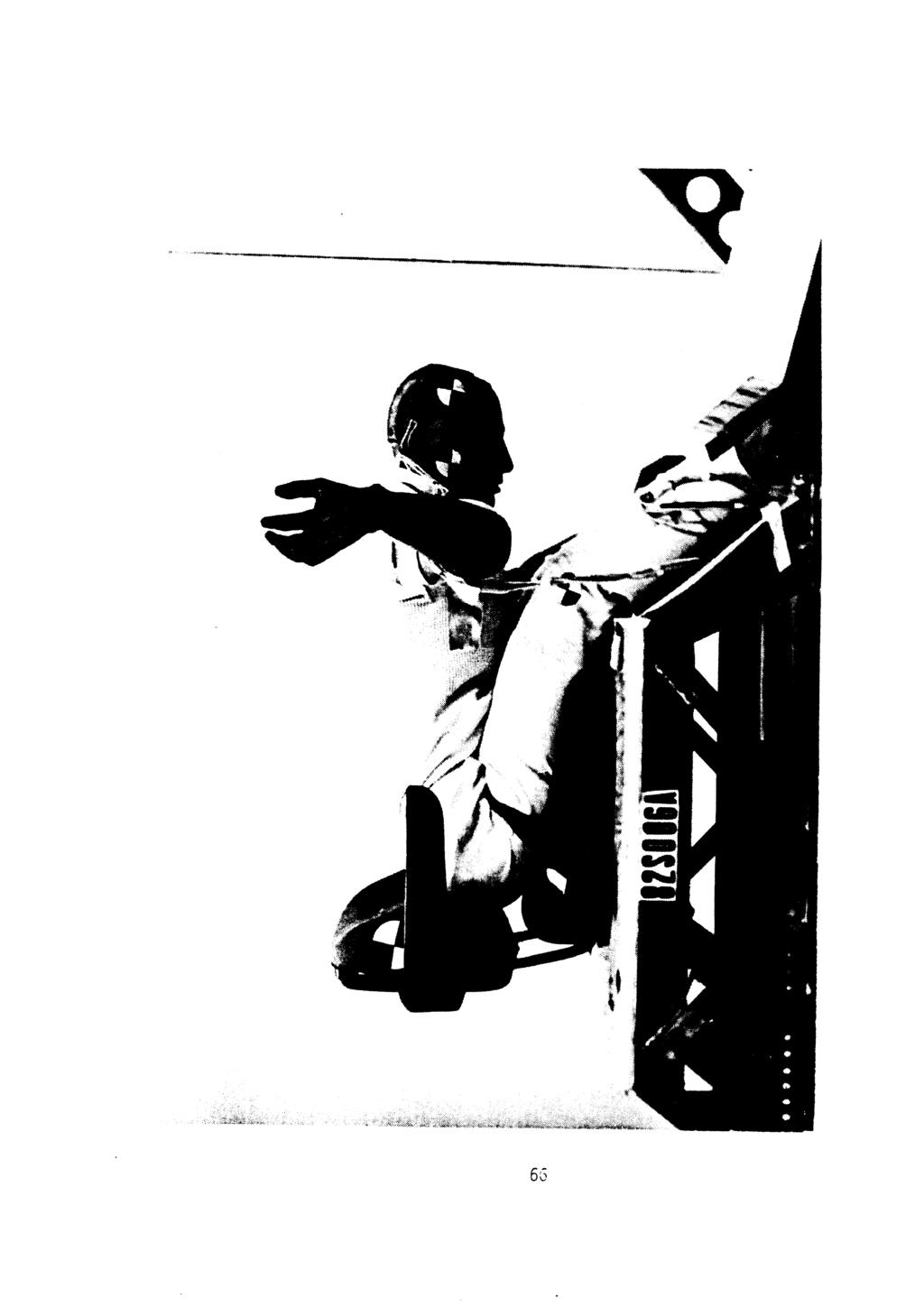
6 11. Test Procedures and Results A total of ten dynamic impact tests were conducted to evaluate the U. S. Steel restraint harness, six on the UMTRI impact sled and four on a vertical shaker platform. A conventional two-inch wide 1 ap be1 t instal 1 a- tion was used for comparison purposes. The sled tests consisted of four frontal and two lateral impacts. The test platform consisted of a forklift seat attached to a fabricated frame. This assembly was rigidly fastened to the impact sled to simulate a typical operator seating configuration. Side and overhead high-speed movies were taken using Photosonics 1-0 cameras operating at 1000 frames per second. A Polaroid Graph-Check seqluence camera provided a "quick-look" at the restraint performance immediate1.y after each test. The shaker platform tests consisted of a single vertical jolt produced by a hydraulic servo system. This facility became available for use during the test program, and provided a more realistic simulation of vertical impacts experienced by equipment operators than could be produced on the sled. A fork lift seat attached to a frame was rigidly fastened to the shaker platform, similar to the impact sled setup. A side view of the jolt test was recorded using a Photosonics 1-0 camera operating at 1000 frames per second,. A 50th percentile male Part 572 dummy instrumented with a triaxial accelerometer array mounted in its head and chest was used in these tests. GSE belt load cells were used to monitor belt webbing forces. These acceleration and force signals were recorded during each impact test on a Honeywell Model 7600 recorder. Table 1 summarizes the impact sled testing of the proposed restraint system. Frontal tests were conducted at; two different severity levels of approximately 18 mph at 30 g and 21 mph at 20 g. The higher velocity produced larger peak excursions of the knees and pelvis with either restraint system. The proposed restraint system gave a 75% greater pelvis excursion than the 1 ap be1 t at 18 mph, and 120% greater excursions at 21 mph. Peak head excursions showed very little sensitivity to either restraint system or impact severity. The significantly higher peak head
7 accelerations and HIC in tests 82S005 and 82S006 resulted from the dummy head's striking the legs. Head/leg interaction also occurred during test 82S002, but the lower test velocity lessened the effect. Lateral tests were conducted at a severity level of 12 mph at 18 g. The proposed restraint system gave a 4% lower peak head excursion and a 9% greater peak pelvis excursion than the conventional two-inch lap be1 t, an i nsi gni fi cant difference. Table I1 summarizes the vertical jolt testing on the shaker platform. The proposed restraint system and the conventional lap belt both provided the same degree of restraint on peak vertical excursions of the head and shoulders. Also, both restraint systems; provided lesser peak vertical excursions than those produced when simulating an unrestrained operator.
8 Table I. Summary of Sled Test Results Test Number: 82S001 82S002 82S003 82S004 82S005 82S006 Restrai nt 2" lap 2" lap 2" lap Sys tem : U.S. Steel be1 t U.S. Steel belt U.S. Steel belt Velocity: (m~h Deceleration : (9) Direction of Impact : Frontal Frontal Lateral Lateral Frontal Frontal Maximum Excursions (inches) HEAD : KNEES : PELVIS : Peak Belt Loads (pounds) RT: LT: Peak Res ul tan t Accelerations (9) HEAD: CHEST : Head Injury Criteria (HIC) :
9
10 111. Discussion From the test results, the proposed restraint system appears to offer comparable protection to a conventional lap be1 t during lateral and vertical impacts, but allows excessive pelvic excursions during a frontal impact. Analysis of the frontal test high-speed movies suggests the higher excursions result from the ability of the short side belts to move fore-. and-aft along the main belt loop. While this provides adjustability so the restraint will fit a wide range of operators, it also appears to feed in additional effective be1 t length during frontal impact. To eliminate this condition, it may be necessary to eliminate or modify the adjustability feature of the short side belts along the main belt loop. Either stitching the side blelts to the main loop or providing several shorter adjustment ranges should reduce the forward excursion of the occupant. Another consideration is the proper length or tension adjustment of the short side belts. For all the impalct tests, these were pretensioned between 12 to 15 pounds to provide consistent initial conditions. However, the short belts are not as easy to tens.ion as a conventional lap belt, increasing the probability of misuse or non-use. A simplified tightening method for the side belts that could be easily performed by a restrained, seated operator should improve usage rates as well as impact performance. For the vertical jolt tests, the proposed severity level of 7 mph at 6 g was not attained. The low excursior~ of the unrestrained operator would suggest retesting at the higher severity to obtain a better comparison of the two restraint systems. A suspension-type seat could not be obtained in time for inclusion in the Phase I1 test program. However, this type of seat was recently evaluated on the UMTRI impact sled using a similar restraint harness. In a frontal impact the entire suspension-type seat rotated forward and remained permanently deformed in this position. This motion allowed the dummy to slide off the end of the seat cushion and submarine under the restraint. Because of the greater pelvis excursions produced by the pro-
11 posed restraint system, the interaction with a suspensi on-type seat and the high potential for submarining should be investigated.
12 IV. Recommendations To improve the impact performance of the proposed restraint system, emphasis should be placed on factors that reduce the pelvis and knee ex- cursions during frontal impacts. These include the following: 8 Ensuring that installation of the harness attaching anchors will provide the recommended 50" + 5" belt angle. Vertical attachments will si gni ficantly increase forward motion during impact. a a Provide an easily performed length adjustment for the short side belts to encourage operators to use the restraint in a correctly tensioned manner. Minimize or eliminate the fore-aft travel of the short side belts along the mai n loop. Thi s adjustabi 1 i ty feature unfortunately degrades frontal impact performance. Additional testing should also be considered to evaluate the following: a The effect of higher severity v'ertical impacts on restraint performance. 0 The interaction of a suspension-type seat with the proposed restraint system to check for potential seat cushion override by the operator, resulting in submarining. r The effectiveness of any a1 ternative modifications to the proposed restraint system design.
13 V. Appendix 1. Test Data Data are arranged in the follow-i ng sequence for each impact test: e e a a a Test summary Data Plots Setup Photograph Graph-Check Photograph Post-Test Photograph
14 Test S umrria ry Test Setup Test Facility: UMTRI Impact Sled Impact Parameters Velocity : 18.2 mph Deceleration : g, with trapezoidal waveform Di recti on : Frontal Restraint System: U. S. Steel Test Results Peak head accelerations P-A (Posteri or-anteri or) : min= -12 g max= 9 g R-L (Right-Left) : min= -11 g max= 6 g I-S ( Inferior-Superior) : min= - 1 g max= 41 g Resultant 42 g HIC (Head Injury Criteria) from to 256 ms Peak chest accelerations P-A ( Posterior-Anteri or) min= -13 g max= 9 g R-L (Right-Left): min= - 3 g max= 5 g I-S ( Inferior-Superior) : min= - 1 g max= 18 g - Resultant 2o g Peak be1 t 1 oads Right side: Left side: - - Maximum Excursions (from H, S. film analysis) Head: Knees : Pel vi s : Observations : pounds pounds inches inches 10.9 inches
15
16
17

18

19

20

21
22 Tes t S umnia ry TEST 8?~007 Test Setup Test Facility: UMTRI Impact Sled Impact Parameters Velocity: Deceleration : Di recti on : Restraint System: 18.5 mph g, with trapezoidal waveform Frontal 2" 1 ap be1 t webbing Test Resul ts Peak head accelerations - P-A (Pos teri or-anteri or) : mjn = -138 g max = 12 g R-L ('~i~ht-left) : min = - 44 g max= 85 g I-S ( Inferior-Superior) : min = - 20 g max= 9 3!I Res ul tant g HIC (Head Injury Criteria) 652 from 149 to 216 ms Peak chest accelerations P-A (Pos terior-anteri or) min=-3fi g max= 6 g R-L (Right-Left) : min=-3 g max= 4 g I-S ( Inferior-Superior) : min= - 3 g max= 20 g - Res ul tant 35 g Peak be1 t loads Right side: Left si ae: Maximum Excursions (from H. Head: Knees : Pel vi s : Observations : - - S. film anislysis) 1631 pounds 1628 pounds inches 7.9 inches 6.2 inches
23
24
25

26
27

28

29

30

31
32 Test S urnnia ry TEST 82S003 Test Setup Test Facility: UMTRI Impact Sled Impact Parameters Velocity : Deceleration : Di rection : 11 ~9mph 18.8 g, with trapezoidal waveform Lateral Restraint System: U. S. Steel Test Results Peak head accelerations P-A (Posteri or-anterior) : min=-2 g max= - 4 g R-L (Ri ght-left) : min= - 8 g max= - 10 g I-S ( Inferior-Superior) : min= -12 g max= 1 g Res ul tant 13 g HIC (Head Injury Criteria) 30 from 150 to 408 ms Peak chest accelerations - P-A (Posterior-Anteri or) min= - 2 g max= 1 g R-L (Right-Left) : min = - 1 g max= - 5 g 1-5 (~nferior-superior) : min=-21 g ma,= 2 g Resultant - 21 g Peak be1 t 1 oads Right side: Left side: Maximum Excursions (from H. Head : Knees : Pel vi s : 601 pounds 37 pounds S. film analysis) - 36g1 inches NA inches 9.7 inches Observations :
33
34
35 o z x
36
37
38

39
40
41
42 Test Sumrr~ary TEST 82S004 Test Setup Test Facility: UMTRI Impact Sled Impact Parameters Velocity : Deceleration : Di rection : Restraint System: 12.Omph 18.4 g, with trapezoidal waveform Lateral 2" lap be1 t webbing Test Resul ts Peak head accelerations P-A (Posteri or-anterior) : min= n g max= 1 g R-L (Ri ght-left) : min= - g max= 7 g I-S (Inferior-Superior) : min= - 3 g max= 2 g Resultant g HIC (Head In jury Cri teria) 135 from 147 to 376 ms Peak chest accelerations - P-A ( Posterior-Anteri or) min= - 3 g max= 3 g R-L (Right-Left) : min= - 5 g max= 1 g I-S ( Inferior-Superior) : min= -11 g max= 1 g - Resultant 12 g Peak be1 t 1 oads Right side: Left side: Maximum Excursions (from H. S. Head: Knees : Pel vi s : 578 pounds - film analysis) 357 pounds - - NA 37.6 inches inches 8.9 inches Observations :
43
44
45
46

47
48

49

50
51 Tes t S umnia ry TEST 82S005 Test Setup Test Facility: UMTRI Impact Sled Impact Parameters Velocity : mph Dece 1 erat i on : 20.3 g, with trapezoidal waveform Di rection : Frontal Restraint System: U. S. Steel Test Res ul ts Peak head accel erati ons P-A (Posterior-Anterior) : min= -50 g max= 6 g R-L (Right-Left) : min= - 9 g max= 42 g I-S ( Inferior-Superior) : min= -57 g max= 0 g Res ul tant -z3-g HIC (Head Injury Criteria) 976 from 118 to 228 ms Peak chest accelerations - P-A (Pos terior-anteri or) min= -27 g max= 1 g R-L ( Right-Left) : min= - 7 g max= 23 g I-S ( Inferior-Superior) : min= -25 g max= 3 g - Res ul tant 32 g Peak belt loads Right side: pounds Left side: pounds Maximum Excursions (from H. S. film analysis) Head: Knees : Pel vi s : Observations : inches 15.6 inches 15.2 inches
52
53
54

55
56
57

58
59
60

61
62 Test Summary Test Setup Test Facility: UMTRI Impact Sled Impact Parameters Velocity : Decel erati on : Di rection : Restraint System: 21-1 mph 20.9 g, with trapezoidal waveform Frontal 2" lap belt webbing Test Results Peak head accelerations P-A (Posteri or-anteri or) : min= -97 g max= 11-5' R-L (Right-Left) : min = -139 g max= 1 4 g I-S ( Inferior-Superior) : min = -95 g max = 7 g Resul tant 194 g - HIC (Head Injury Criteria) 1439 from 119 to 226 ms Peak chest accelerations - P-A ( Posterior-Anteri or) min= -66 g max= 12 g - - R-L (Right-Left) : min = -11 g max = 17 g I-S ( Inferior-Superior) : min= -33 g max= 45 g Resul tant 9 71 Peak be1 t 1 oads Right side: Left side: - - Maximum Excursions (from H. S. film analysis) Head : Knees : Pel vi s : Observations : 1922 pounds 1632 pounds inches 8.4 inches 6.9 inches
63
64
65

66

67
68
69
70
71
72
73 Test Surnnary TEST Test Setup Test Facility : Vertical Shaker PI atform Impact Parameters I Platfonn Motion : Upward jolt and return Pulse Shape: Triangular displacement wavefom Peak Platform Acceleration: 2.2 g Restraint System: U. S. Steel Restraint Harness Test Results Peak head accelerations P-A (Posteri or-anterior) : min = -2 g max = g R-L (Ri ght-left) : min = -2 g max= ' g I-S (Inferior-Superior) : min = - 3 g max = 6 g Resul tant 6 g HIC (Head Injury Criteria) - 1 from 97 to 614 ms Peak chest accelerations P-A (Pos teri or-anteri or) min=-1 - g max= 1 g R-L (Right-Left) : min= 0 g max= 0 g I-S ( Inferior-Superior) : min=-3 g max= g Res ul tant - g Peak be1 t 1 oads Right side: 56 pounds Left side: - 67 pounds Maximum Excursions (from H. S. film analysis) Head: -.9 inches Shoul der : inches Observations :
74
75
76 a a," - c Ln a," 0%
77
78
79 Test Sumnary Test Setup Test Facility:. Vertical Shaker Platform Impact Parameters I Platform Motion : Upward jolt and return Pulse Shape: Tri angular di spl acement waveform Peak Platform Acceleration: 1.6 g Restraint System: U. S. Steel Restraint Harness Test Results Peak head accelerations P-A (Posteri or-anteri or) : min= -7 g max= 1 g R-L (Right-Left) : min= -7 g max= 1 g I-S ( Inferior-Superior) : min = -3 g rnax = 5 g Resultant L g HIC (Head Injury Criteria) - 1 from 133 to 575 ms Peak chest accelerations P-A (Posteri or-anteri or) min=-2 g max= 1 g R-L ( Right-Left) : min=-1 - g max= 0 g I-S ( Inferior-Superior) : min = -3 g max = 6 g Resultant - g Peak be1 t 1 oads Right side: 65 pounds Left side: - 64 pounds Maximum Excursions (from H. Head: Shoul der: Observations : S. film analysis) inches inches
80
81
82
83
84
85 Test Sumnary TEST 82S009 Test Setup Test Facility: Vertical Shaker Platform Impact Parameters I Platform Motion : Upward jol t of 5.7 inches and return in 370 ms Pulse Shape: Tri angul ar di spl acement wavefom Peak Platform Acceleration: 2.5 g Restraint System: None Test Results Peak head accelerations P-A (Posteri or-anteri or) : min = -4 g max = g R-L (Ri ght-left) : min = -2 g max= 1 g I-S ( Inferior-Superior) : min = -7 g max = g Res ul tant - g HIC (Head Injury ~ rteria) i 1 from 442 to 482 ms Peak chest accelerations P-A (Pos terior-anteri or) min = -2 g max = 1 g R-L (Right-Left) : min= 0 g max= 1 g I-S ( Inferior-Superior) : mint 8 g max= 3 g Resultant - g Peak be1 t loads Right side: Left side: Maximum Excursions (from H. Head: Shoul der: Observations : S. film analysis) pounds - pounds inches 2.6 inches
86
87
88
89
90
91 Test Sumnary TEST 82SOlO Test Setup Test Facility : Vertical Shaker PI atfom Impact Parameters I Platform Motion : Upward jolt of 5.7 inches and return in 370 ins Pulse Shape: Triangular displacement waveform Peak Platform Acceleration: 2.8 g Restraint System: 2 inch wide lap be1 t webbing Test Resul ts Peak head accelerations P-A (Posteri or-anterior) : min= -2 g max= 1 g R-L (Ri ght-left) : min= -2 g max= 1 g I-S ( Inferior-Superior) : min = -3 g max = 4 g Resul tant 4 g HIC (Head Injury Criteria) - 1 from 44 to543 ms Peak chest accelerations P-A (Posteri or-anteri or) min = -2 g max = ' g R-L (Right-Left): min = 0 g max= ' g I -S (~nferior-superior) : min= -4 g max= g Resultant Peak be1 t loads Right side: Left side: Maximum Excursions (from H. Head: Shoulder: Observations : - S. film analysis) 86 pounds 75 pounds - inches l a 8 inches -
92
93
94
95

96
97
METHODOLOGY FOR ESTIMATING THORACIC IMPACT RESPONSE IN FRONTAL CRASH TESTS
 METHODOLOGY FOR ESTIMATING THORACIC IMPACT RESPONSE IN FRONTAL CRASH TESTS Craig P. Thor, Hampton C. Gabler Virginia Tech-Wake Forest, Center for Injury Biomechanics ABSTRACT This study has investigated
CALIBRATION AND TEST PROCEDURES FOR 3-YEAR-OLD-CHILD FINAL REPORT. Joseph B. Benson John W. Melvin
 CALIBRATION AND TEST PROCEDURES FOR 3-YEAR-OLD-CHILD DUMMY FINAL REPORT Joseph B. Benson John W. Melvin Contract Number: DOT-HS-6-01367 Contract Amount: $35,639.00 Submitted by: Highway Safety Research
Paulitz 1 FULLY-ADAPTIVE SEATBELTS FOR FRONTAL COLLLISIONS
 FULLY-ADAPTIVE SEATBELTS FOR FRONTAL COLLLISIONS Timothy J. Paulitz Donald M. Blackketter Karl K. Rink National Institute for Advanced Transportation Technology Department of Mechanical Engineering University
Road vehicles Dummies for restraint system testing Part 1: Adult dummies
 ISO 2013 All rights reserved ISO TC 22/SC 12/WG 5 N1019 Date: 2013-02-20 ISO/PDTR 12349-1/WD 12349-1 ISO TC 22/SC 12/WG 5 Secretariat: AFNOR Road vehicles Dummies for restraint system testing Part 1: Adult
Comparison of head and thorax cadaver and Hybrid III responses to a frontal sled deceleration for the validation of a car occupant mathematical model
 Comparison of head and thorax cadaver and Hybrid III responses to a frontal sled deceleration the validation of a car occupant mathematical model Philippe Vezin, Karine Bruyère, François Bermond INRETS-LBMC
MAPPING THE RAINFALL EVENT FOR STORMWATER QUALITY CONTROL
 Report No. K-TRAN: KU-03-1 FINAL REPORT MAPPING THE RAINFALL EVENT FOR STORMWATER QUALITY CONTROL C. Bryan Young The University of Kansas Lawrence, Kansas JULY 2006 K-TRAN A COOPERATIVE TRANSPORTATION
ANALY S IS OF DAISY TRACK HUMAN TOLERANCE TESTS. Final Report Draft James H. McEl haney Verne 1. Roberts. D. Hurl ey Robbi ns.
 ANALY S S OF DASY TRACK HUMAN TOLERANCE TESTS Final Report Draft James H. McEl haney Verne 1. Roberts D. Hurl ey Robbi ns February 10, 1971 HSR Report No. Bio M-71-1 ANALYSS OF DASY TRACK HUMAN TOLERANCE
q Icon TM Backs (Low, Mid, Tall, Deep ) $ q Evolution TM Backs (Regular, Tall, Deep ) $
 $ q Evolution TM Backs (Regular, Tall, Deep ) $") Distributed in Canada by 49 Bespoke, Inc. 51 Caldari Road, Units 6-7B Concord, ON L4K 4G3 Phone: (866) 827-4548 Fax: (877) 731-7745 sales@kimobility.ca www.kimobilty.ca Company: Account Number: Date: q
Distributed in Canada by 49 Bespoke, Inc. 51 Caldari Road, Units 6-7B Concord, ON L4K 4G3 Phone: (866) 827-4548 Fax: (877) 731-7745 sales@kimobility.ca www.kimobilty.ca Company: Account Number: Date: q
A.R.M. 52 PLOW With QUICK ATTACH MOUNTING SYSTEM MODEL NUMBER BLACK MODEL NUMBER GRAY. Owner s Manual
 70 8TH AVE W PO BOX 7 SPENCER, IA 0 PHONE: 7-6-9 FAX: 7-6-08 SERVICE: 800-8- E-MAIL: ccac@cyclecountry.com www.cyclecountry.com A.R.M. PLOW With QUICK ATTACH MOUNTING SYSTEM MODEL NUMBER 0-00 BLACK MODEL
Improving Safety Features during a Head on Collision inside a Car Cabin
 Improving Safety Features during a Head on Collision inside a Car Cabin Harinarayan Vishwakarma Abstract The core theme of this research is directed towards the idea of providing more safety features inside
External Pressure... Thermal Expansion in un-restrained pipeline... The critical (buckling) pressure is calculated as follows:
 pressure is calculated as follows:") External Pressure... The critical (buckling) pressure is calculated as follows: P C = E. t s ³ / 4 (1 - ν ha.ν ah ) R E ³ P C = Critical buckling pressure, kn/m² E = Hoop modulus in flexure, kn/m² t s
External Pressure... The critical (buckling) pressure is calculated as follows: P C = E. t s ³ / 4 (1 - ν ha.ν ah ) R E ³ P C = Critical buckling pressure, kn/m² E = Hoop modulus in flexure, kn/m² t s
HRN/HRN-C Series Hydraulic Vane Rotary Actuators
 HRN/ Hydraulic Vane Rotary Actuators Vane Actuators Tork-Mor HRN Contents Features... 2 Ordering Information... Engineering Data / Specifications... Dimensions... Features... 1 Ordering Information...12
Selection table for guided systems (crank driven)
") Selection table for guided systems (crank driven) One mass shaker brute-force system One mass shaker natural frequency system Two mass shaker fast-runner system with reaction force-compensation Single
Selection table for guided systems (crank driven) One mass shaker brute-force system One mass shaker natural frequency system Two mass shaker fast-runner system with reaction force-compensation Single
Biomechanical Modelling of Musculoskeletal Systems
 Biomechanical Modelling of Musculoskeletal Systems Lecture 6 Presented by Phillip Tran AMME4981/9981 Semester 1, 2016 The University of Sydney Slide 1 The Musculoskeletal System The University of Sydney
AP Physics Free Response Practice Dynamics
 AP Physics Free Response Practice Dynamics 14) In the system shown above, the block of mass M 1 is on a rough horizontal table. The string that attaches it to the block of mass M 2 passes over a frictionless
ER2 Short-head Electric Chain Hoist
 O/M NO.SHER2-0903-CE-00 ER2 Short-head Electric Chain Hoist (250kg to 5t) Operation Manual (SHER2M/SHER2SG/SHER2SP) Introduction The KITO Short-head Electric Chain Hoist is intended for effective use in
Test Report No.: GZHL HM Date: Aug 08, 2016 Page 1 of 10
 Test Report No.: GZHL1607032559HM Date: Aug 08, 2016 Page 1 of 10 ZHEJIANG BIO INDUSTRY&TRADE CO.,LTD NUM 1269,BADA ROAD,QIUBIN INDUSTRY PARK,JINHUA,CITY,ZHEJIANG PTOVINCE,CHINA. The following sample(s)
Test Report No.: GZHL HM-01 Date: Aug 16, 2016 Page 1 of 10
 Test Report No.: GZHL1608034628HM-01 Date: Aug 16, 2016 Page 1 of 10 ZHEJIANG BIO INDUSTRY&TRADE CO.,LTD NUM 1269,BADA ROAD,QIUBIN INDUSTRY PARK,JINHUA,CITY,ZHEJIANG PTOVINCE,CHINA. The following sample(s)
Fig Use Fig. 3.1 to state the physical properties of this metal. In your answer, you should use appropriate technical terms, spelled correctly.
 1 (a) Fig. 3.1 shows the stress against strain graph for a metal X up to its breaking point. stress X 0 0 Fig. 3.1 strain Use Fig. 3.1 to state the physical properties of this metal. In your answer, you
The subject of this paper is the development of a design
 The erformance and Design Checking of Chord-Angle Legs in Joist Girders THEODORE V. GALAMBOS ABSTRACT The subject of this paper is the development of a design checking method for the capacity of the outstanding
Physics 18 Spring 2011 Homework 3 Wednesday February 2, 2011
 Physics 18 Spring 2011 Homework 3 Wednesday February 2, 2011 Make sure your name is on your homework, and please box your final answer. Because we will be giving partial credit, be sure to attempt all
SHARK Snow Plow. 52 (132 cm) / 60 (152 cm) Complete system blade INSTRUCTIONS / ESTABLISHMENT
 / 60 (152 cm) Complete system blade INSTRUCTIONS / ESTABLISHMENT") SHARK Snow Plow 52 (132 cm) / 60 (152 cm) Complete system blade INSTRUCTIONS / ESTABLISHMENT OPERATING INSTRUCTIONS Congratulations! You ve just purchased the most durable plow system in the industry.
SHARK Snow Plow 52 (132 cm) / 60 (152 cm) Complete system blade INSTRUCTIONS / ESTABLISHMENT OPERATING INSTRUCTIONS Congratulations! You ve just purchased the most durable plow system in the industry.
Lesson 25. Static Pile Load Testing, O-cell, and Statnamic. Reference Manual Chapter 18
 Lesson 25 Static Pile Load Testing, O-cell, and Statnamic Reference Manual Chapter 18 STATIC LOAD TESTING Most accurate method to determine static pile capacity Perform at design or construction stage
ON THE KINEMATICS OF THE HEAD USING LINEAR ACCELERATION MEASUREMENTS*
 1. Biomechanics, 1976, Vol, 9, pp, 67-611 Pergamon Press. Printed in Great Britain ON THE KINEMATICS OF THE HEAD USING LINEAR ACCELERATION MEASUREMENTS* e. e. CHOUand S. e. SINHA Biomechanics Research
Figure 2.1 The Inclined Plane
 PHYS-101 LAB-02 One and Two Dimensional Motion 1. Objectives The objectives of this experiment are: to measure the acceleration due to gravity using one-dimensional motion, i.e. the motion of an object
AP Physics 1 Dynamics Free Response Problems ANS KEY
 AP Physics 1 Dynamics ree Response Problems ANS KEY 1. A block of mass m, acted on by a force directed horizontally, slides up an inclined plane that makes an angle θ with the horizontal. The coefficient
Operating Instructions For the Series Weavexx Tensometer Instrument
 Operating Instructions For the 12-0000 Series Weavexx Tensometer Instrument Description The Weavexx Tensometer is a patented instrument for measuring tension in flexible, thin textile conveyor belts, paper,
Transactions on the Built Environment vol 22, 1996 WIT Press, ISSN
 A shock damage potential approach to shock testing D.H. Trepess Mechanical Subject Group, School of Engineering, Coventry University, Coventry CVl 5FB, UK A shock damage (excitation capacity) approach
EXPECTED BELT-SPECIFIC INJURY PATTERNS DEPENDENT ON THE ANGLE OF IMPACT
 EXPECTED BELT-SPECIFIC INJURY PATTERNS DEPENDENT ON THE ANGLE OF IMPACT D Adomei t, H Goegler*, V Vu Han Institute of Automotive Engineering Technische Universität Berl in, Germany *Surgical Department
INSTALLATION INSTRUCTIONS ProVantage Plow Pulley Part Number: 84526
 ProVantage Plow Pulley Part Number: 84526 GENERAL SAFETY PRECAUTIONS Your safety, and the safety of others, is very important. To help you make informed decisions about safety, we have provided installation
PHYSICS LICENCE. 6 Marks
 PHYSICS LICENCE 1. A SPEED CAMERA TAKES TWO PHOTOGRAPHS AT HALF-SECOND INTERVALS OF A MOTOR CYCLIST DRVING ALONG THE MOTORWAY. DESCRIBE HOW THESE COULD BE USED TO CALCULATE THE SPEED OF THE MOTOR CYCLIST.
Chapter 2: FORCE and MOTION
 Chapter 2: FORCE and MOTION Linear Motion Linear motion is the movement of an object along a straight line. Distance The distance traveled by an object is the total length that is traveled by that object.
Chapter: Motion, Acceleration, and Forces
 Table of Contents Chapter: Motion, Acceleration, and Forces Section 1: Describing Motion Section 2: Acceleration Section 3: Motion and Forces 1 Motion Are distance and time important in describing running
Exam 2 - Part I 28 questions No Calculator Allowed. x n D. e x n E. 0
 1. If f x! ( ) = ln e A.!n x " x n # $ Exam - Part I 8 questions No Calculator Allowed, and n is a constant, then f % ( x) = B. x n e C.!1 x n D. e x n E. 0. Let f be the function defined below. Which
Can Delta-V be Adjusted with Structural and Occupant Restraint Performance to Improve Prediction of Chest Acceleration?
 Can Delta-V be Adjusted with Structural and Occupant Restraint Performance to Improve Prediction of Chest Acceleration? Douglas J. Gabauer, MSE, Hampton C. Gabler, PhD Center for Injury Biomechanics Virginia
Clausing Industrial, Inc. Variable Speed 20" Single and Multi-spindle, Belt Drive Industrial Drill Presses
 www.clausing-industrial.com Variable Speed 20" Single and Multi-spindle, Belt Drive Industrial Drill Presses Clausing Industrial, Inc. Two Speed Variable Speeds 150-2000rpm Variable Speeds 200-1300rpm
MECTROL CORPORATION 9 NORTHWESTERN DRIVE, SALEM, NH PHONE FAX TIMING BELT THEORY
 MECTRO CORPORATION 9 NORTHWESTERN DRIVE, SAEM, NH 03079 PHONE 603-890-55 FAX 603-890-66 TIMING BET THEORY Copyright 997, 999, 00 Mectrol Corporation. All rights reserved. April 00 Timing Belt Theory Introduction
FORCE TABLE INTRODUCTION
 FORCE TABLE INTRODUCTION All measurable quantities can be classified as either a scalar 1 or a vector 2. A scalar has only magnitude while a vector has both magnitude and direction. Examples of scalar
Edward C. Robison, PE, SE. 02 January Architectural Metal Works ATTN: Sean Wentworth th ST Emeryville, CA 94608
 Edward C. Robison, PE, SE ks ATTN: Sean Wentworth 1483 67 th ST Emeryville, CA 94608 02 January 2013 SUBJ: 501 CORTE MADERA AVE, CORTE MADERA, CA 94925 BALCONY GUARD BASE PLATE MOUNTS The guards for the
DRIFTER PLOW-IN-A-BOX ASSEMBLY / OWNER S MANUAL
 DRIFTER PLOW-IN-A-BOX ASSEMBLY / OWNER S MANUAL Part No: 10-0550 OPERATING INSTRUCTIONS Congratulations! You ve just purchased one of the industry s top plow systems. The DRIFTER Plow System works great
Simulation of Occupant Posture Change during Autonomous Emergency Braking and Occupant Kinematics in Frontal Collision.
 Simulation of Occupant Posture Change during Autonomous Emergency Braking and Occupant Kinematics in Frontal Collision. Katsunori Yamada, Mitsuaki Gotoh, Yuichi Kitagawa, Tsuyoshi Yasuki Abstract Occupant
Chapter: Motion, Acceleration, and Forces
 Table of Contents Chapter: Motion, Acceleration, and Forces Section 1: Describing Motion Section 2: Acceleration Section 3: Motion and Forces 1 Motion Are distance and time important in describing running
Selection Calculations For Linear & Rotary Actuators
 H-8 For Electric Linear Slides and Electric Cylinders First determine your series, then select your product. Select the actuator that you will use based on the following flow charts: Selection Procedure
Centripetal Force Lab
 Centripetal Force Lab Saddleback College Physics Department, adapted from PASCO Scientific 1. Purpose To use a PASCO apparatus containing a rotating brass object to confirm Newton s Second Law of rotation
EQUATIONS OF MOTION: GENERAL PLANE MOTION (Section 17.5) Today s Objectives: Students will be able to analyze the planar kinetics of a rigid body
 Today s Objectives: Students will be able to analyze the planar kinetics of a rigid body") EQUATIONS OF MOTION: GENERAL PLANE MOTION (Section 17.5) Today s Objectives: Students will be able to analyze the planar kinetics of a rigid body undergoing general plane motion. APPLICATIONS As the soil
EQUATIONS OF MOTION: GENERAL PLANE MOTION (Section 17.5) Today s Objectives: Students will be able to analyze the planar kinetics of a rigid body undergoing general plane motion. APPLICATIONS As the soil
AP PHYSICS: Lab #4 Projectile Motion Lab
 AP PHYSICS: Lab #4 Projectile Motion Lab Mr. O Hagan Oct. 11, 2010 I SUMMARY This lab was performed to determine if the equations of motion accurately predict projectile motion. Calculations were made
Motion and Forces study Guide
 Motion and Forces study Guide Completion Complete each statement. 1. The motion of an object looks different to observers in different. 2. The SI unit for measuring is the meter. 3. The direction and length
BioRID-II Dummy Model Development. Stochastic Investigations
 BioRID-II Dummy Model Development -- Stochastic Investigations Sebastian Stahlschmidt*, Bastian Keding*, K. Witowski*, H. Müllerschön*, U. Franz* *DYNAmore GmbH, Stuttgart, Germany Abstract: Whiplash injuries
SPECIAL CONDITION. Water Load Conditions. SPECIAL CONDITION Water Load Conditions
 Doc. No. : SC-CVLA.051-01 Issue : 1d Date : 04-Aug-009 Page : 1 of 13 SUBJECT : CERTIFICATION SPECIFICATION : VLA.51 PRIMARY GROUP / PANEL : 03 (Structure) SECONDARY GROUPE / PANEL : -- NATURE : SCN VLA.51
UTC ETT160. Incorporation of Hands-on Experiments in an Introductory Structural Analysis Course
 Incorporation of Hands-on Experiments in an Introductory Structural Analysis Course By John J. Myers, Ph.D., P.E. Trevor Hrynyk Ashraf Ayoub, Ph.D., P.E. Abdeldjelil Belarbi, Ph.D., P.E. William Schonberg,
Snow Blade Operator s/assembly Instructions
 Snow Blade Operator s/assembly Instructions TABLE OF CONTENTS Safety Messages...3 Introduction...4 Preparing for Snow Removal...4 Operating Procedure...5 Operating Controls...5 Tire Chains and Wheel Weights...5
MODEL NAME : LLDMWW0-15K*0*A
 Eagle Eye (Outdoor LED Module) Application Note MODEL NAME : LLDMWW0-15K*0*A RoHS Compliant HALOGEN FREE (30)-4022 1 / 16 CONTENTS 1. Product Description 3/16 2. Specifications 2.1. Chromaticity Bins for
The Effect of Inflated Backrest Stiffness on Shearing Loads Estimated with Articulated Total Body
 The Effect of Inflated Backrest Stiffness on Shearing Loads Estimated with Articulated Total Body Bob J. Scurlock, Ph.D., ACTAR *, James R. Ipser, Ph.D. *, Paul A. Borsa, Ph.D., ATC, FACSM # * Department
Designation: NWI DIF Horizontal Hail impact Standard
 Designation: NWI DIF Horizontal Hail impact Standard 2.1.2015 Standard Test Method for Materials attached to Vertical or Near Vertical Surfaces and Their Resistance to Horizontally Propelled Freezer Ice
APPENDIX. SELECTING THE SureServo SERVO SYSTEM. In This Appendix... Selecting the SureServo Servo System...B 2. Leadscrew - Example Calculations...
 SELECTING THE SureServo SERVO SYSTEM APPENDIX B In This Appendix... Selecting the SureServo Servo System............B 2 The Selection Procedure......................................B 2 How many pulses
Project Engineer: Wesley Kinkler Project Number: 4.14 Submission Date: 11/15/2003. TAMUK Truss Company Trusses Made Simple
 Submission Date: 11/15/2003 TAMUK Truss Company Trusses Made Simple Table of Contents Introduction..3 Proposal.3 Solution..5 Hand Calculations 5 TRUSS2D 7 NENastran 7 Comparison of Results... 8 Data Analysis.10
COMPUTER SIMULATION OF AN AIRBAG-RESTRAINED PASSENGER IN IMPACT SIMULATOR AND CRASH BARRIER TESTS: DEVELOPMENT OF. Final Report
 COMPUTER SIMULATION OF AN AIRBAG-RESTRAINED PASSENGER IN IMPACT SIMULATOR AND CRASH BARRIER TESTS: DEVELOPMENT OF AN IMPROVED PROCEDURE FOR USING A HYGE SLED Final Report Prepared by Bruce M. Bowman, Research
THE LOSMANDY G-11 MOUNT
 Checking the parts THE LOSMANDY G-11 MOUNT Depending on which accessories you ordered, your G-11 mount was shipped in four or more boxes. The contents of each box are as follows: Equatorial Mount Adjustable
Research of Side Crash Sled Test based on Recursive Least Square Method
 International Conference on Mechatronics, Electronic, Industrial and Control Engineering (MEIC 2014) Research of Side Crash Sled Test based on Recursive Least Square Method Dong Liping donglipingshamo@163.com
Failure in Flexure. Introduction to Steel Design, Tensile Steel Members Modes of Failure & Effective Areas
 Introduction to Steel Design, Tensile Steel Members Modes of Failure & Effective Areas MORGAN STATE UNIVERSITY SCHOOL OF ARCHITECTURE AND PLANNING LECTURE VIII Dr. Jason E. Charalambides Failure in Flexure!
INSTALLATION INSTRUCTIONS ATV SNOW PLOW Mounting Kit: PN Application: HONDA 400
 INSTALLATION INSTRUCTIONS ATV SNOW PLOW Mounting Kit: PN 37851 Application: HONDA 400 Your safety, and the safety of others, is very important. To help you make informed decisions about safety, we have
ATV WP2 FRONT MOUNT PUSH TUBE
 ATV WP2 FRONT MOUNT PUSH TUBE ASSEMBLY / OWNER S MANUAL Part No: 16-0000 MAN0352 Rev. 00 OPERATING INSTRUCTIONS Congratulations! You ve just purchased the most durable plow component in the industry. Cycle
Angular Motion Maximum Hand, Foot, or Equipment Linear Speed
 Motion Maximum Hand, Foot, or Equipment Linear Speed Biomechanical Model: Mo3on Maximum Hand, Foot, or Equipment Linear Speed Hand, Foot, or Equipment Linear Speed Sum of Joint Linear Speeds Principle
DEVELOPMENT OF DROP WEIGHT IMPACT TEST MACHINE
 CHAPTER-8 DEVELOPMENT OF DROP WEIGHT IMPACT TEST MACHINE 8.1 Introduction The behavior of materials is different when they are subjected to dynamic loading [9]. The testing of materials under dynamic conditions
MHS. Applied Math. Sample Questions. Exam to go from grade 11 to grade 12
 MHS Applied Math Exam to go from grade 11 to grade 1 Sample Questions 1. OP + PA + AR = 1. OPAR. AR 3. OR. Given two vectors u and v in the box below, how can we correctly find their sum, u + v, using
Academic Physics Mechanics. Chapter 10 Center of Gravity
 1 Academic Physics Mechanics Chapter 10 Center of Gravity 10.1: Center of Gravity 2 The center of gravity of an object is the point located at the objects average position of weight. For a symmetrical
Introduction to Geohazard Standard Specification for Simple Drapery
 Introduction to Geohazard Standard Specification for Simple Drapery Up to now, there is no standard specification for geohazard solutions in North America. Often projects specifications are referring to
Engineering Reference
 Engineering Reference Sizing and Selection of Exlar Linear and Rotary Actuators Move Profiles The first step in analyzing a motion control application and selecting an actuator is to determine the required
Semester 1 Final Exam Review Answers
 Position (m) Mass (g) Semester 1 Final Exam Review Answers A physics student was interested in finding the mass of a penny. To do so she grabbed a bunch of pennies and placed them on a scale. She gathered
Chapter 5 Review. 1. [No Calculator] Evaluate using the FTOC (the evaluation part) 2. [No Calculator] Evaluate using geometry
![Chapter 5 Review. 1. [No Calculator] Evaluate using the FTOC (the evaluation part) 2. [No Calculator] Evaluate using geometry](/thumbs/80/81403863.jpg "Chapter 5 Review. 1. [No Calculator] Evaluate using the FTOC (the evaluation part) 2. [No Calculator] Evaluate using geometry") AP Calculus Chapter Review Name: Block:. [No Calculator] Evaluate using the FTOC (the evaluation part) a) 7 8 4 7 d b) 9 4 7 d. [No Calculator] Evaluate using geometry a) d c) 6 8 d. [No Calculator] Evaluate
AP Calculus Chapter Review Name: Block:. [No Calculator] Evaluate using the FTOC (the evaluation part) a) 7 8 4 7 d b) 9 4 7 d. [No Calculator] Evaluate using geometry a) d c) 6 8 d. [No Calculator] Evaluate
RGS08 Linear Rails: RGS08 Non-Motorized With and Without Guide Screw. RGS08 Non-Motorized Linear Rails
 RGS08 RGS08 Non-Motorized With and Without Guide RGS08 Non-Motorized Linear Rails RG Series linear rails are available: RGS08 Non-Motorized, -driven linear rail RGS08 Non-Motorized linear rail without
frictionless horizontal surface. The bullet penetrates the block and emerges with a velocity of o
 AP Physics Free Response Practice Momentum and Impulse 1976B2. A bullet of mass m and velocity v o is fired toward a block of mass 4m. The block is initially at rest on a v frictionless horizontal surface.
AAPT UNITED STATES PHYSICS TEAM AIP 2008
 8 F = ma Exam AAPT UNITED STATES PHYSICS TEAM AIP 8 8 F = ma Contest 5 QUESTIONS - 75 MINUTES INSTRUCTIONS DO NOT OPEN THIS TEST UNTIL YOU ARE TOLD TO BEGIN Use g = N/kg throughout this contest. You may
TEXAS TRANSPORTATION INSTITUTE TEXAS A&M RESEARCH FOUNDATION TECHNICAL MEMORANDUM TESTING PROGRAM SAFETY PROVISIONS FOR SUPPORT STRUCTURES
 TEXAS TRANSPORTATION INSTITUTE TEXAS A&M RESEARCH FOUNDATION TECHNICAL MEMORANDUM 605-4 TESTING PROGRAM SAFETY PROVISIONS FOR SUPPORT STRUCTURES ON OVERHEAD SIGN BRIDGES By D. L. Ivey, R. M. Olson, Eugene
R a t i o n a l i s e d B r a k e A c t u a t o r s
 C o m m e r c i a l V e h i c l e S y s t e m s P r o d u c t C a t a l o g u e R a t i o n a l i s e d B r a k e A c t u a t o r s... for Air Disc Brake applications Disclaimer The information contained
U.S. Standard for Revolving Pedestrian Doors Seriously Flawed
 U.S. Standard for Revolving Pedestrian Doors Seriously Flawed Warren F. Davis, Ph.D. Davis Associates, Inc. 43 Holden Road Newton, MA 02465-1909 June 21, 2009 Introduction The current version of the American
December 1999 FINAL TECHNICAL REPORT 1 Mar Mar 98
 REPORT DOCUMENTATION PAGE AFRL-SR- BL_TR " Public reporting burden for this collection of information is estimated to average 1 hour per response, including the time for reviewing instruct the collection
Lecture T2 The Pendulum-Based Start Gate (US 8,016,639 B2)
") 1 Lecture T2 The Pendulum-Based Start Gate (US 8,016,639 B2) INTRODUCTION Literally millions of Pinewood Derby races have been run since the inception of the race in 1953, mostly by Cub Scouts and their
1 Lecture T2 The Pendulum-Based Start Gate (US 8,016,639 B2) INTRODUCTION Literally millions of Pinewood Derby races have been run since the inception of the race in 1953, mostly by Cub Scouts and their
1. Introduction. 1.1 Overview of Study:
 1. Introduction 1.1 Overview of Study: Hot and cold fluid passing through long pipes causes thermal expansion and contraction in the piping system. The fluid passing through pipes also creates fluctuations
From Test Collisions to Stiffness Coefficients
 From Test Collisions to Stiffness Coefficients Jon Neades. AiTS, South Cerney, Glos. Abstract The use of computer programs to estimate the changes in velocity (Delta-V) suffered by a vehicle in a collision
PLOW MOUNT KIT FOR POLARIS RANGER P/N ASSEMBLY / OWNERS MANUAL
 PLOW MOUNT KIT FOR POLARIS RANGER P/N 34-3010 ASSEMBLY / OWNERS MANUAL Application PLOW PUSH FRAME NO. 34-0000 or 34-0070 Before you begin, please read these instructions and check to be sure all parts
AN Motion Control Products Application note Linear and s-ramped velocity profiles
 Motion Control Products Application note Linear and s-ramped velocity profiles AN- The Mint motion profiler automatically calculates the required velocity profile for an axis based on a number of key settings
FRICTIONAL FORCES. Direction of frictional forces... (not always obvious)... CHAPTER 5 APPLICATIONS OF NEWTON S LAWS
... CHAPTER 5 APPLICATIONS OF NEWTON S LAWS") RICTIONAL ORCES CHAPTER 5 APPLICATIONS O NEWTON S LAWS rictional forces Static friction Kinetic friction Centripetal force Centripetal acceleration Loop-the-loop Drag force Terminal velocity Direction
RICTIONAL ORCES CHAPTER 5 APPLICATIONS O NEWTON S LAWS rictional forces Static friction Kinetic friction Centripetal force Centripetal acceleration Loop-the-loop Drag force Terminal velocity Direction
The Young modulus is defined as the ratio of tensile stress to tensile strain. Explain what is meant by each of the terms in italics.
 1 (a) The Young modulus is defined as the ratio of tensile stress to tensile strain. Explain what is meant by each of the terms in italics. tensile stress tensile strain (b) A long wire is suspended vertically
( m/s) 2 4(4.9 m/s 2 )( 52.7 m)
 2 4(4.9 m/s 2 )( 52.7 m)") Version 072 idterm 2 OConnor (05141) 1 This print-out should have 18 questions ultiple-choice questions may continue on the next column or page find all choices before answering V1:1, V2:1, V3:3, V4:5,
Version 072 idterm 2 OConnor (05141) 1 This print-out should have 18 questions ultiple-choice questions may continue on the next column or page find all choices before answering V1:1, V2:1, V3:3, V4:5,
( m/s) 2 4(4.9 m/s 2 )( 53.2 m)
 2 4(4.9 m/s 2 )( 53.2 m)") Version 074 idterm 2 OConnor (05141) 1 This print-out should have 18 questions ultiple-choice questions may continue on the next column or page find all choices before answering V1:1, V2:1, V3:3, V4:5,
Version 074 idterm 2 OConnor (05141) 1 This print-out should have 18 questions ultiple-choice questions may continue on the next column or page find all choices before answering V1:1, V2:1, V3:3, V4:5,
14010 Force Table Student Guide
 Recommended Accessories: Scissors Level (to adjust the legs of the apparatus) Blank paper or graph paper Pencil Ruler Protractor Calculator Optional Accessories: Paper clips 14010 Force Table Student Guide
Figure Two. Then the two vector equations of equilibrium are equivalent to three scalar equations:
 2004- v 10/16 2. The resultant external torque (the vector sum of all external torques) acting on the body must be zero about any origin. These conditions can be written as equations: F = 0 = 0 where the
Mark scheme Mechanics Year 1 (AS) Unit Test 7: Kinematics 1 (constant acceleration)
 Unit Test 7: Kinematics 1 (constant acceleration)") 1a Figure 1 General shape of the graph is correct. i.e. horizontal line, followed by negative gradient, followed by a positive gradient. Vertical axis labelled correctly. Horizontal axis labelled correctly.
1a Figure 1 General shape of the graph is correct. i.e. horizontal line, followed by negative gradient, followed by a positive gradient. Vertical axis labelled correctly. Horizontal axis labelled correctly.
Series Shrink Boot Adapters. Series Shrink Boot, EMI/RFI, Strain Relief. Series Shrink Boot, EMI/RFI, Shield Sock
 Product Selection Guide How For a complete Table of Contents please see the last page of this book Series 310 - Shrink Boot Adapters The adapters in this section are designed to accommodate lipped-type
APPENDIX A.1 TEST PROTOCOLS
 APPENDIX A.1 TEST PROTOCOLS The National Wind Institute, Debris Impact Test Facility (NWI - DIF) at Texas Tech University (TTU) performs debris impact tests on storms shelters, shelter components, and
Thanks. You Might Also Like. I look forward helping you focus your instruction and save time prepping.
 Thanks Connect Thank you for downloading my product. I truly appreciate your support and look forward to hearing your feedback. You can connect with me and find many free activities and strategies over
VX25 Enclosure System. Technical documentation PE conductor connection, current carrying capacity
 VX Enclosure System Technical documentation PE conductor connection, current carrying capacity Enclosure system VX Contents Contents. General remarks. Introduction. Notes on the design of the earthing
LDR Series BOX PLOW INSTALLATION & OWNER S MANUAL TABLE OF CONTENTS
 LDR Series BOX PLOW INSTALLATION & OWNER S MANUAL TABLE OF CONTENTS SAFETY... 2 INTRODUCTIONS... 5 TIPS ON PLOWING SNOW... 6 BOX PLOW ASSEMBLY PROCEDURE... 7 BOX PLOW BLADE ASSEMBLY DRAWING AND PARTS LIST...
EXPERIMENTAL EVALUATION OF SHEAR STRENGTH OF WOVEN WEBBINGS
 EXPERIMENTAL EVALUATION OF SHEAR STRENGTH OF WOVEN WEBBINGS Kevin L. Peil +, Ever J. Barbero +, Eduardo M. Sosa* + Department of Mechanical and Aerospace Engineering, West Virginia University (WVU), Morgantown,
Uniform Circular Motion
 Slide 1 / 112 Uniform Circular Motion 2009 by Goodman & Zavorotniy Slide 2 / 112 Topics of Uniform Circular Motion (UCM) Kinematics of UCM Click on the topic to go to that section Period, Frequency, and
Inverted Pendulum System
 Introduction Inverted Pendulum System This lab experiment consists of two experimental procedures, each with sub parts. Experiment 1 is used to determine the system parameters needed to implement a controller.
Tie Bar Extension Measuring Chain
 Force Tie Bar Extension Measuring Chain Type 9827A... for Clamped or Screwed Installation in Injection Molding Machines Tie bar ex ten sion meas ur ing chain con sist ing of a quartz longi tu di nal meas
HVTT 11: Truck Occupant Protection Considerations in Heavy Truck Crashes
 TRUCK OCCUPANT PROTECTION CONSIDERATIONS IN HEAVYVEHICLE CRASHES Peter Hart graduated with a PhD in electrical engineering from Monash University in 1990. He is the principal of Hartwood Consulting Pty
INSTALLATION INSTRUCTIONS ATV SNOW PLOW Mounting Kit: PN Application: HONDA MODELS: 450S AND 450ES
 INSTALLATION INSTRUCTIONS ATV SNOW PLOW Mounting Kit: PN 37852 Application: HONDA MODELS: 450S AND 450ES Your safety, and the safety of others, is very important. To help you make informed decisions about