Three-Dimensional CFD FLYGT Mixer Model and Results
|
|
|
- Frank Young
- 5 years ago
- Views:
Transcription

1 WSRC-TR KEYWORDS: Mixer Model CFD Approach Mixer Shroud Model Propeller Model Asymmetric Wall Jet Model RETENTION - Permanent Three-Dimensional CFD FLYGT Mixer Model and Results SAVANNAH RIVER TECHNOLOGY CENTER Si Young Lee and Richard A. Dimenna Publication Date: June, 2000 Westinghouse Savannah River Company Savannah River Site Aiken, SC Prepared for the U.S. Department of Energy under Contract No. DE-AC09-96SR18500
2 This document was prepared in conjunction with work accomplished under Contract No. DE-AC09-96SR18500 with the U. S. Department of Energy. DISCLAIMER This report was prepared as an account of work sponsored by an agency of the United States Government. Neither the United States Government nor any agency thereof, nor any of their employees, makes any warranty, express or implied, or assumes any legal liability or responsibility for the accuracy, completeness, or usefulness of any information, apparatus, product or process disclosed, or represents that its use would not infringe privately owned rights. Reference herein to any specific commercial product, process or service by trade name, trademark, manufacturer, or otherwise does not necessarily constitute or imply its endorsement, recommendation, or favoring by the United States Government or any agency thereof. The views and opinions of authors expressed herein do not necessarily state or reflect those of the United States Government or any agency thereof. This report has been reproduced directly from the best available copy. Available for sale to the public, in paper, from: U.S. Department of Commerce, National Technical Information Service, 5285 Port Royal Road, Springfield, VA 22161, phone: (800) , fax: (703) online ordering: Available electronically at Available for a processing fee to U.S. Department of Energy and its contractors, in paper, from: U.S. Department of Energy, Office of Scientific and Technical Information, P.O. Box 62, Oak Ridge, TN , phone: (865) , fax: (865) reports@adonis.osti.gov
3 (This Page Intentionally Left Blank) -ii-
4 DOCUMENT: TITLE: WSRC-TR Three-Dimensional CFD FLYGT Mixer Model and Results APPROVALS Date: Si Y. Lee, Author (EM&S Group/EDS/SRTC) Date: Richard A. Dimenna, Coauthor (EM&S Group/EDS/SRTC) Date: Glenn A. Taylor, Technical Reviewer (Process Engineering) Date: Cynthia P. Holding-Smith, Manager (EM&S Group/SRTC) Date: Martha A. Ebra, Manager (EDS/SRTC) Date: Brannen J. Adkins, Customer (Waste Removal Engineering) -iii-
5 (This Page Intentionally Left Blank) -iv-
6 Table of Contents Summary 1 1. Background and Objective 2 2. Model Descriptions and Solution Methods 3 3. Investigation of the Nominal Pump Operating Conditions Results and Discussions Steady-State Results Sensitivity Run Results Non-uniform Inlet Flow Condition Shroud Wall Roughness Pump Rotational Speed Transient Flow Behavior of FLYGT Mixer Associated with Pump Cavitation Conclusions Recommendations References 65 -v-
7 (This Page Intentionally Left Blank) -vi-
8 List of Figures Figure 1. Analysis methodology for FLYGT mixer models...6 Figure 2. Modeling boundary for three-dimensional FLYGT mixer model...7 Figure 3. Meshes on three-dimensional domain...9 Figure 4. The blade and shaft surface grid after two repetitions of periodic boundary...10 Figure 5. Two-dimensional meshes at exit plane after two periodic repetitions of the present model...11 Figure 6. Overview of segregated solution method for the present model...12 Figure 7. Comparison of predictions with test data...14 Figure 8. Determination of pump operating conditions...15 Figure 9. Axial velocity distribution as a function of liquid level at the 40ft distance from the shroud exit based on two-dimensional wall jet model (Lee and Dimenna, 2000) for 9000 gpm pump flowrate. Inlet velocity is uniformly 45 o skewed against the axial flow direction (θ in = 45 o in the figure)...16 Figure 10. Axial velocity distributions as a function of liquid depth at various distances distance from the shroud exit based on two-dimensional wall jet model (Lee and Dimenna, 2000) for 9,000 gpm pump flowrate. Inlet velocity is increased linearly along the radial direction...17 Figure 11. Velocity vector plot near the shroud region predicted by the two-dimensional wall jet model (Lee and Dimenna, 2000) for 9,000 gpm pump flowrate. Inlet velocity is increased linearly along the radial direction Figure 12. Velocity distributions near the shroud region and over the whole computational domain predicted by two-dimensional wall jet model (Lee and Dimenna, 2000) for 9,000 gpm pump flowrate. Inlet velocity is increased linearly along the radial direction...19 Figure 13. Typical static pressure distribution at downstream and upstream regions near the leading-edge tip of single pump blade for 860rpm of pump rotational speed and 9,000 gpm flow condition (Propeller blade shown in the figure rotates clockwise.) Figure 14. Typical fluid flow pattern and rotation profile at downstream and upstream regions near the leading-edge tip of single pump blade for 860rpm of pump -vii-
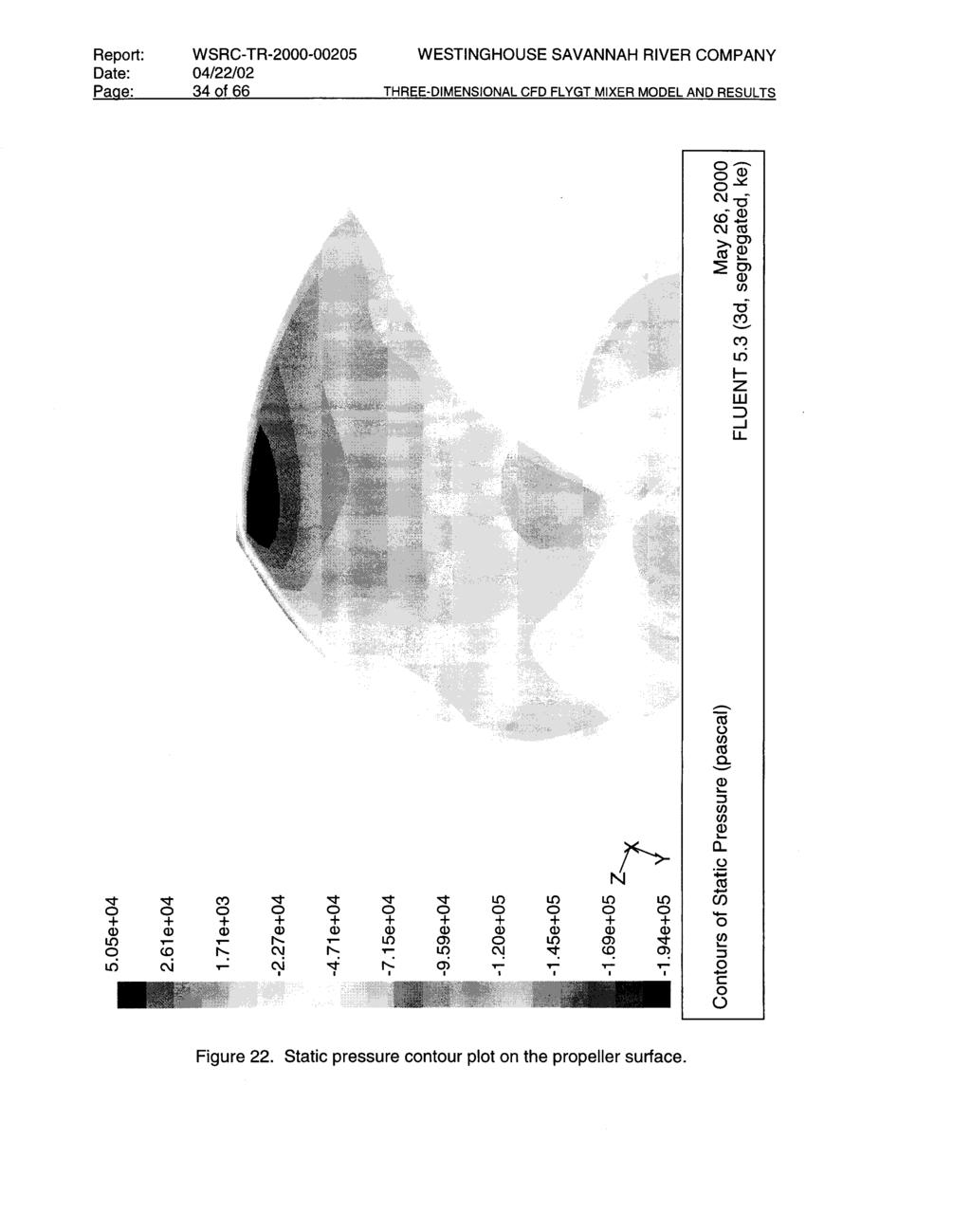
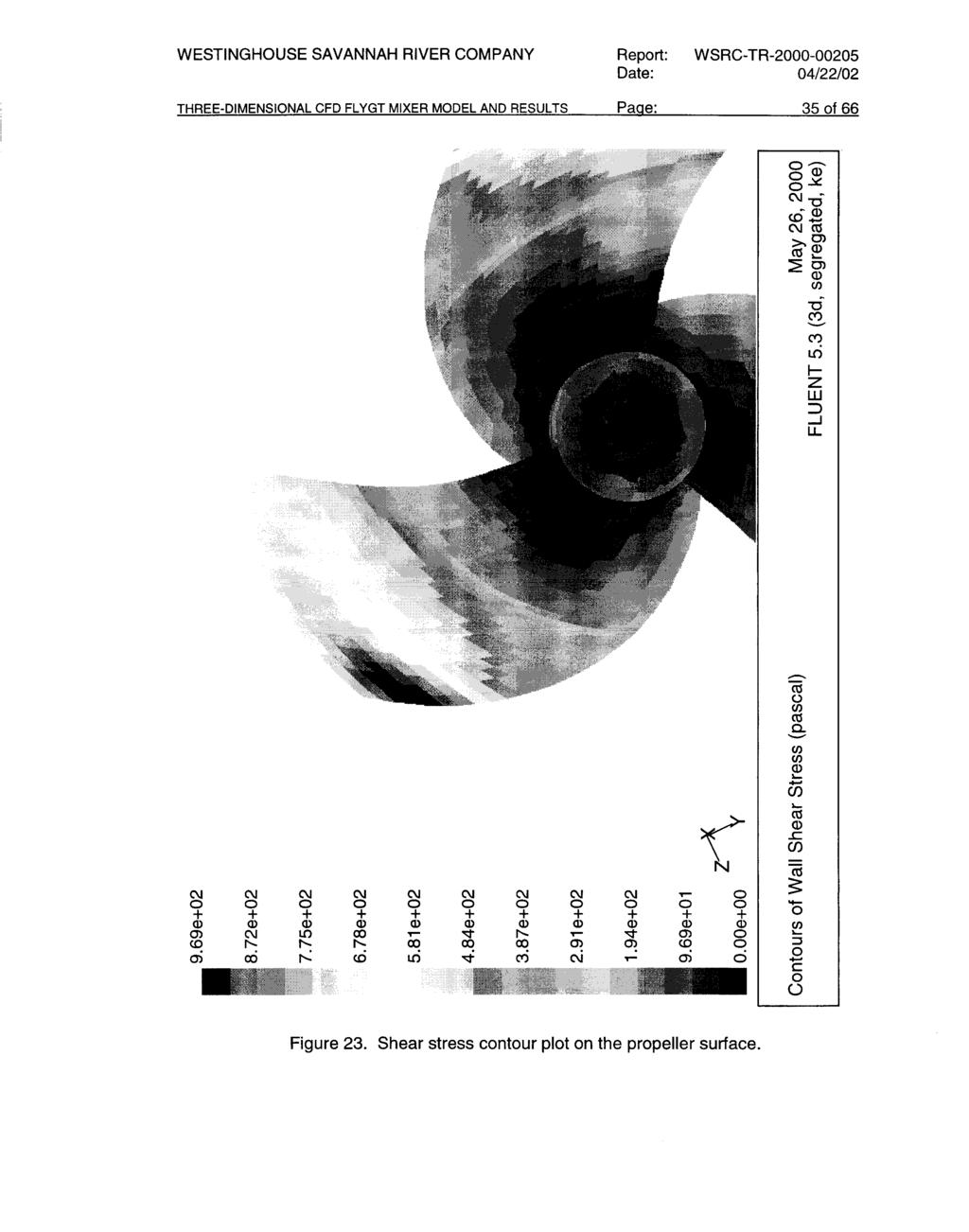
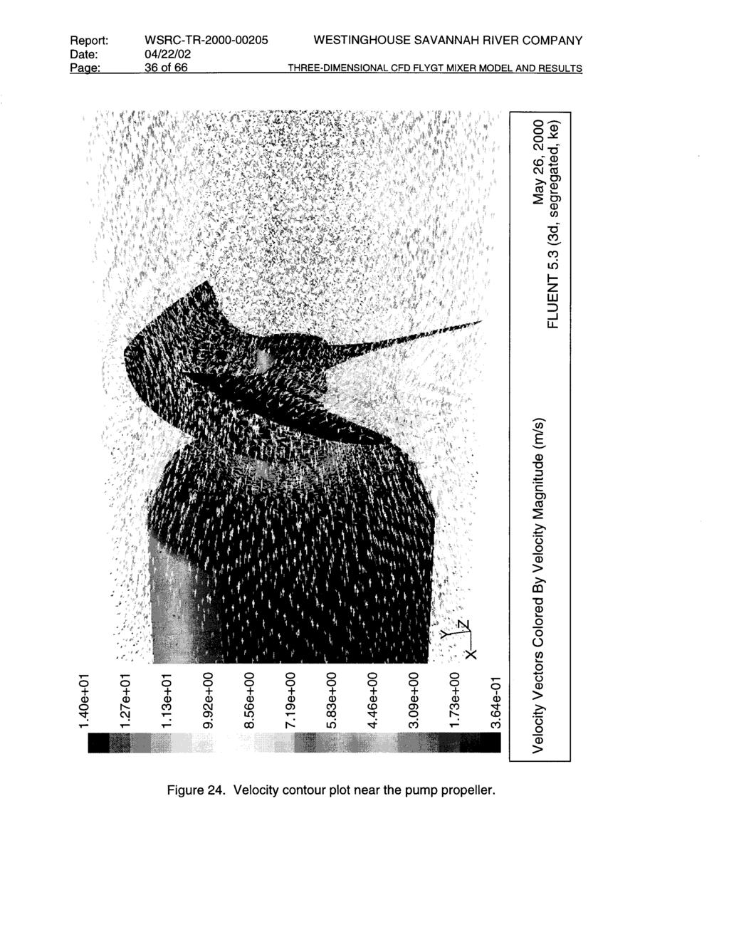
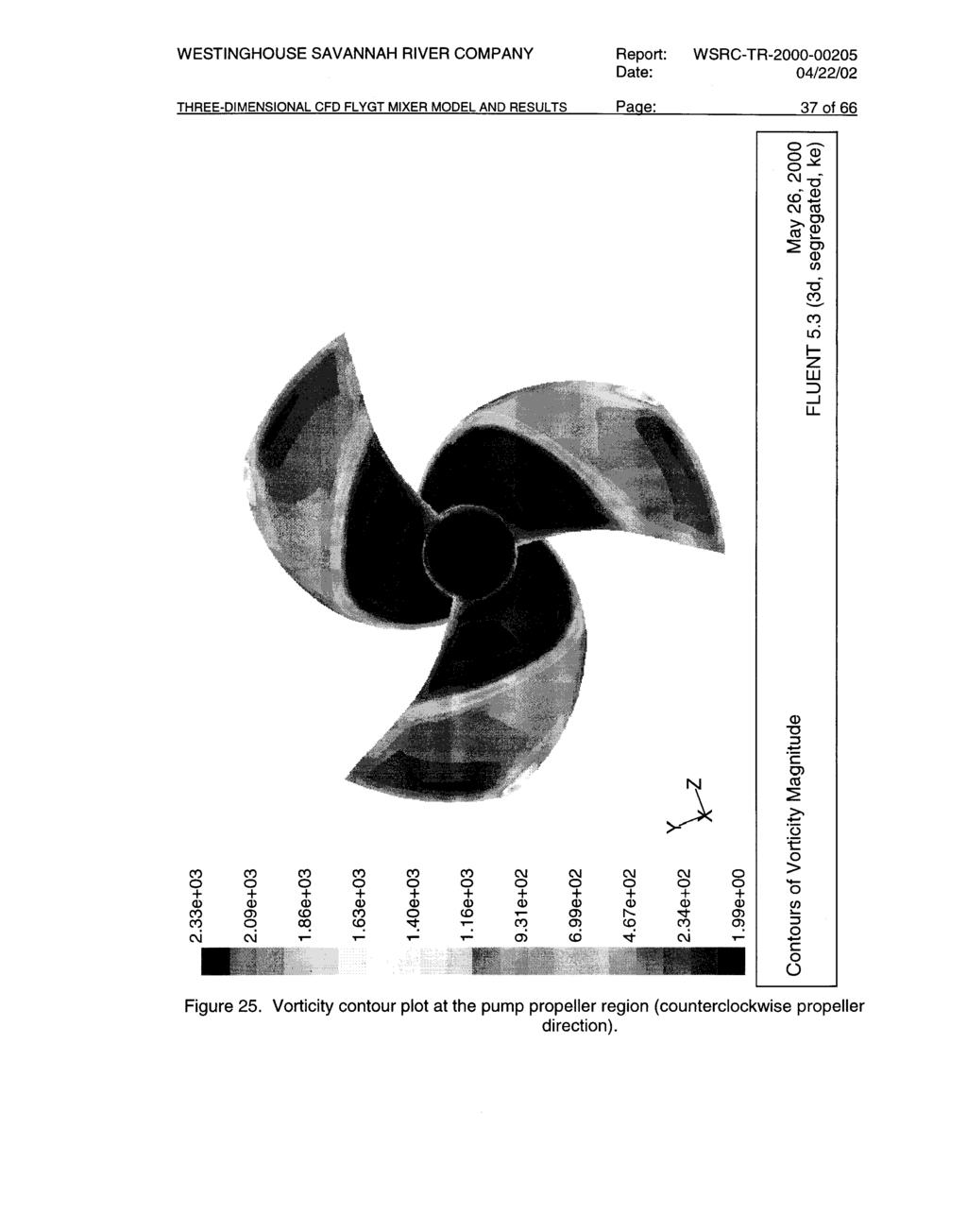
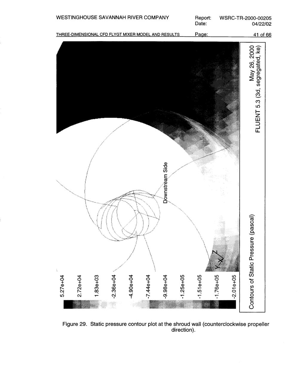
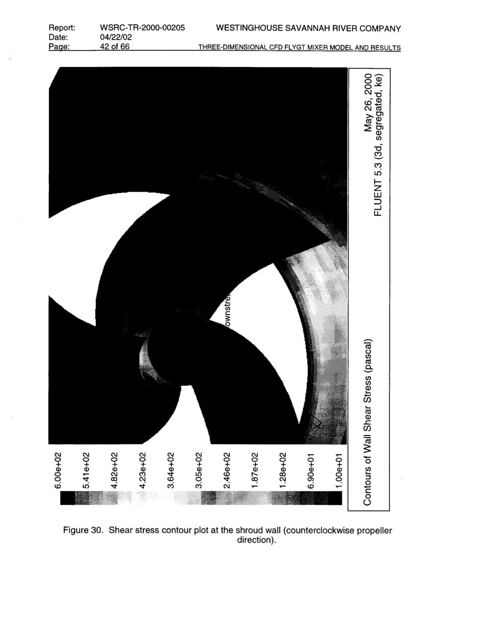
9 rotational speed and 9,000 gpm flow condition (Propeller blade shown in the figure rotates clockwise.)...26 Figure 15. Load on each component of the FLYGT mixer along the axial flow direction for 860rpm of pump rotational speed (Loads for propeller and shroud wall region are negative forces) Figure 16. Radial velocity vector plots at the plane crossing the leading tip of the blade for various rotational speeds of 9,000 gpm pump flowrate...28 Figure 17. Static pressure contour plots at the plane crossing the leading tip of the blade for various rotational speeds of 9,000 gpm pump flowrate...29 Figure 18. Vorticity contour plots at the plane crossing the leading tip of the blade for various rotational speeds of 9,000 gpm pump flowrate...30 Figure 19. Pressure distributions along the axial flow direction (line A-A ) crossing the leading-edge tip of the propeller blade for 9,000 gpm flow condition as a function of pump speed...31 Figure 20. Fluid vorticity distributions along the axial flow direction (line A-A ) crossing the leading-edge tip of the propeller blade for 9,000 gpm flow condition as a function of pump speed e...32 Figure 21. Turbulence intensity contour plots at the plane crossing the leading tip of the blade for various rotational speeds of 9,000 gpm pump flowrate...33 Figure 22. Static pressure contour plot on the propeller surface Figure 23. Shear stress contour plot on the propeller surface...35 Figure 24. Velocity contour plot near the pump propeller Figure 25. Vorticity contour plot at the pump propeller region (counterclockwise propeller direction)...37 Figure 26. Vorticity contour plot at the propeller hub region (counterclockwise propeller direction)...38 Figure 27. Static pressure contour plot at the propeller hub region (counterclockwise propeller direction)...39 Figure 28. Shear stress contour plot at the propeller hub region (counterclockwise propeller direction)...40 Figure 29. Static pressure contour plot at the shroud wall (counterclockwise propeller direction)...41 Figure 30. Shear stress contour plot at the shroud wall (counterclockwise propeller direction) viii-
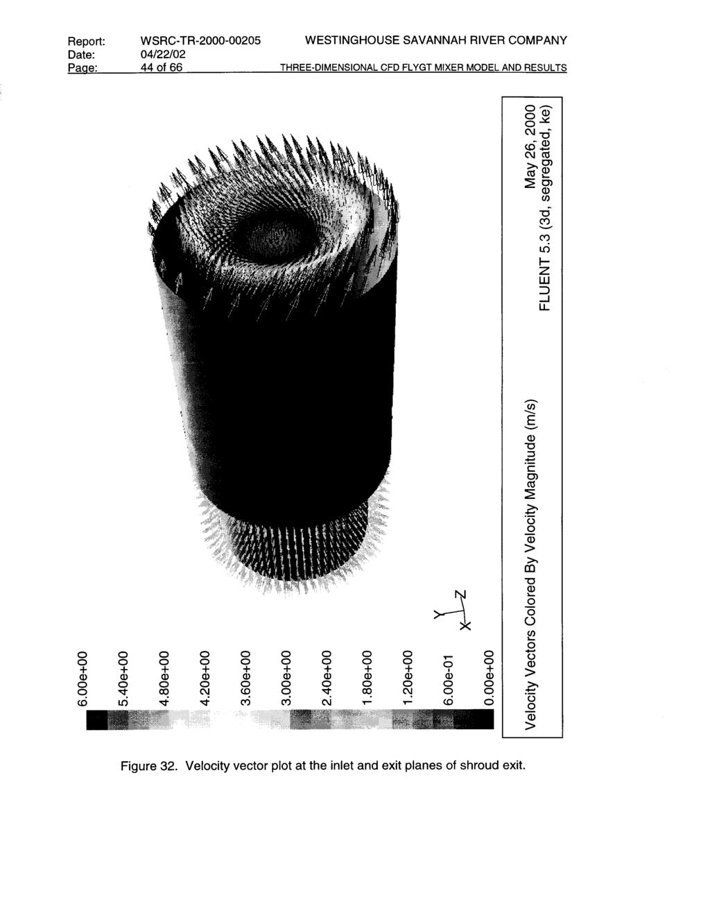
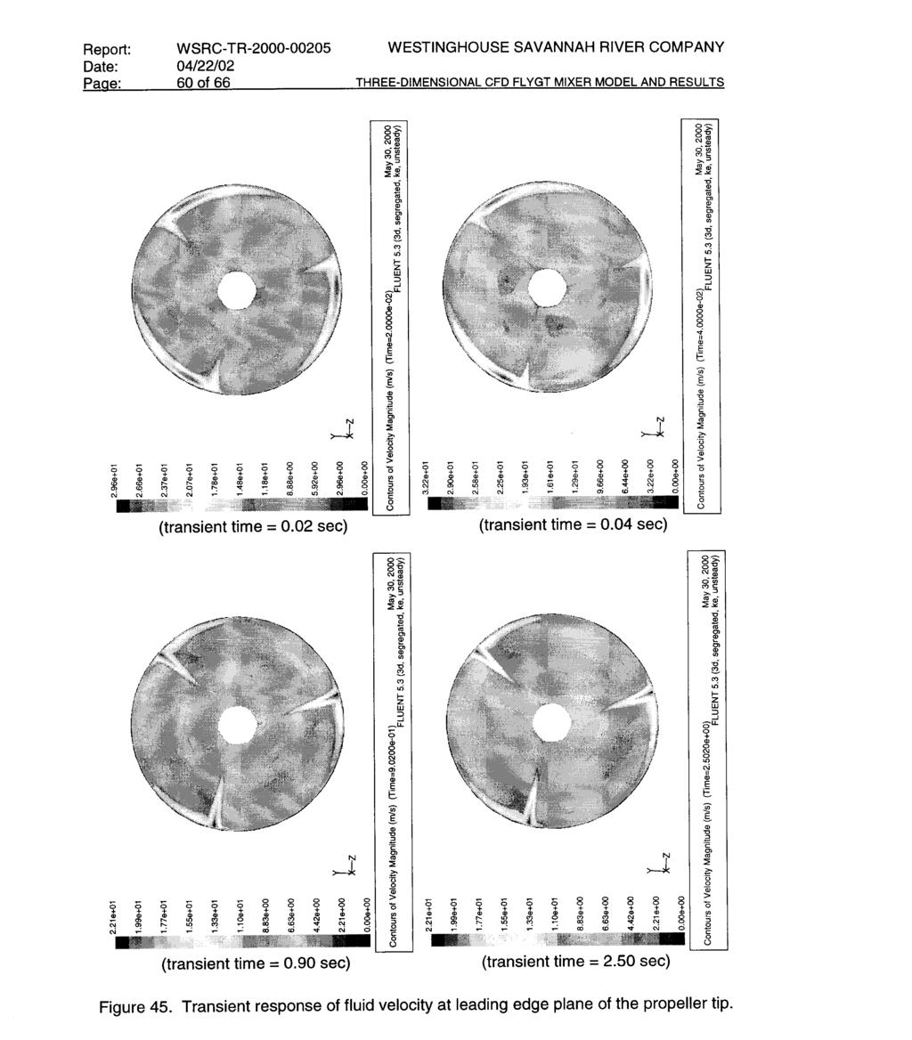
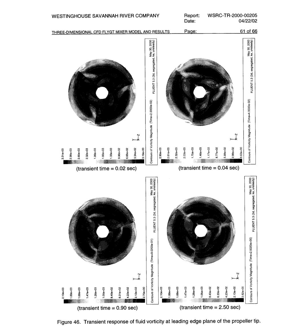
10 Figure 31. Velocity distributions along the radial direction...43 Figure 32. Velocity vector plot at the inlet and exit planes of shroud exit...44 Figure 33. Non-uniform and uniform flow conditions at the pump inlet for the sensitivity runs...46 Figure 34. Sensitivity run results for axial flow velocities at shroud exit...46 Figure 35. Velocity vector plot at the inlet and exit planes for non-uniform inlet flow condition...48 Figure 36. Sensitivity run results for surface roughness effects of shroud wall on axial flow velocities at shroud exit (Roughness height of rough wall used in this figure was 0.01ft equivalent to concrete surface.)...49 Figure 37. Sensitivity run results for pump speed effects on axial flow velocities at the exit of the pump shroud under 9,000 gpm flow and 860 rpm pump speed...50 Figure 38. Transient response of flow velocity along the radial direction of the shroud exit plane for 12,000 gpm and 860 rpm operating condition Figure 39. Transient response of axial flow velocity along the radial direction of the shroud exit plane for 12,000 gpm and 860 rpm operating condition...54 Figure 40. Transient response of total pressure force for three propeller blades under 12,000 gpm and 860 rpm operating condition Figure 41. Transient response of pressure force for hub under 12,000 gpm and 860 rpm operating condition...56 Figure 42. Transient response of pressure force for shroud wall under 12,000 gpm and 860 rpm operating condition...57 Figure 43. Transient response of static pressure at leading-tip edge plane of the propeller...58 Figure 44. Transient response of fluid density at leading edge plane of the propeller tip...59 Figure 45. Transient response of fluid velocity at leading edge plane of the propeller tip...60 Figure 46. Transient response of fluid vorticity at leading edge plane of the propeller tip...61 Figure 47. Transient velocity distributions at the exit of the shroud for 700 rpm pump speed and gpm flow condition Figure 48. Transient response of total pressure force for three propeller blades under gpm flow with two pump speeds ix-
11 -x-
12 (This Page Intentionally Left Blank) -xi-
13 List of Tables Table 1. Modeling purpose and descriptions for Tank 19 FLYGT mixer...35 Table 2. Potential ranges of flow conditions for Tank 19 FLYGT mixer...8 Table 3. Absolute pressures near the leading-edge tip of the pump blade under 9,000 gpm water flowrate of steady-state operating condition...21 Table 4. Maximum axial and radial velocities for various pump speeds at the leading-edge tip of the pump blade under 9,000 gpm flow constraint of steady-state operating condition...21 Table 5. Axial forces along the flow direction for propeller, hub, and shroud regions under wide range of steady-state pump operating conditions...24 Table 6. Comparison of minimum pressure coefficients (C p,min ) for three different advance coefficients (J) corresponding to three rotational pump speeds...24 Table 7. Influence of inlet flow non-uniformity on the axial loads of pump blade, shaft, and shroud wall regions under steady-state operating conditions of two different flows with 860 rpm pump speed...47 Table 8. Influence of shroud wall roughness on the axial loads of pump blade, shaft, and shroud wall regions under 9,000 gpm flow and 860 rpm pump speed of steadystate operating condition...47 Table 9. Influence of rotational pump speed on the axial loads of pump blade, shaft, and shroud wall regions under 9,000 gpm flow of steady-state operating condition in a smooth shroud wall...50 Table 10. Summary of load sensitivities to the changes of the physical parameters for the propeller blade for 9,000 gpm flow and 860 rpm operating condition (Negative number means decrease in load.) xii-
14 (This Page Intentionally Left Blank) -xiii-
15 WESTINGHOUSE SAVANNAH RIVER COMPANY Report: WSRC-TR Date: 04/22/02 THREE-DIMENSIONAL CFD FLYGT MIXER MODEL AND RESULTS Page: 1 of 66 Summary Since mid-february, the Engineering Development Section (EDS) has been assisting the High Level Waste (HLW) customer to assess the failure causes of the FLYGT mixer to be used to recover waste from Tank 19 and to redesign the mixer. In support of this project, two Computational Fluid Dynamics (CFD) models have been developed. They are a steady-state pump model and a transient model considering the effects of vapor formation due to pump cavitation. The commercial CFD code, FLUENT, is used in the present analysis. The computations are performed for a three-dimensional model of the FLYGT mixer with the prototypic propeller shape. In the models, the propeller is assumed to be symmetrical and perfectly-balanced within a rigid and stationary shroud boundary under any operating condition. Both of the models include the propeller region, the inlet region upstream of the propeller, and the downstream shroud region as computational domain. The areas of focus for the analysis presented here are the flow performance of the modified mixer under potential operating conditions and the loads on the propeller, shaft, and shroud regions of the mixer. Calculated physical parameters include velocity profiles of axial flow, cavitation locations, and loads on the shroud wall, propeller blade, and hub of the propeller for the operating flow conditions. As inlet boundary conditions of the model, uniform radial and axial velocities through the shroud inlet and around the motor housing are used assuming azimuthally symmetrical flow conditions. An operating flow condition of 9,000 gpm is established by the comparison of the steadystate model predictions and HLW test data (Adkins, 2000) at the shroud exit. The results of the model show that the modified mixer has reasonable performance for 9,000 gpm flow and 500 rpm pump speed in terms of flow behavior and spread angle near the exit. Sensitivity runs are performed for non-uniform inlet velocity along the axial flow direction, different surface roughness of the shroud inner wall, and different pump speeds. From the model results, the non-uniform inlet velocity and wall roughness effects are found to have a negligible effect on overall flow patterns at the inner and outlet regions of the shroud, loads on each pump component, and cavitation size near the tip of the blade as long as liquid flow rate remains constant. The primary reason for these results is that turbulent flow effect within the shroud is dominant due to the high-speed rotations of axial propeller. Thus, it is noted that pump speed is the most sensitive one among the three parameters in terms of flow performance and pump loading. Transient model results show that transient flow behavior such as change of fluid density and loadings of the mixer establish steady-state conditions within about 1 second, corresponding to about 40 cycles of the propeller blade, after the initiation of the pump cavitation. In addition, a low density region is established near the peripheral region adjacent to the shroud wall because all bubbles generated as a result of cavitation migrate to the high-velocity fluid region near the tip of the propeller blade.
16 Report: WSRC-TR WESTINGHOUSE SAVANNAH RIVER COMPANY Date: 04/22/02 Page: 2 of 66 THREE-DIMENSIONAL CFD FLYGT MIXER MODEL AND RESULTS 1. Background and Objective The Engineering Modeling and Simulation Group (EMSG) was asked to perform an analysis which could provide pertinent information in support of a modified High-Level Waste (HLW) Tank 19 FLYGT mixer design. The modified FLYGT mixer will be used to recover waste from the Tank 19. Under normal operating conditions, the mixer will be oriented in a horizontal position above approximately 6 to 7 inches above the bottom of the 85 ft diameter tank. In this situation, the discharge from the shroud exit is the driving force for liquid mixing and material suspension from the tank floor. In previous work (Lee and Dimenna, 2000), two two-dimensional models were developed to determine the optimum shroud length for acceptable flow performance and to conduct sensitivity analysis for a wide range of possible boundary conditions at the shroud inlet downstream of the pump propeller. One model was axisymmetric using the shroud alone without the pump propeller as a modeling boundary. The other model was a twodimensional wall jet model to investigate asymmetric effects of the shroud discharge flow. For the previous analysis (Ref. 8) and the present work, a Computational Fluid Dynamics (CFD) approach has been taken. In the present analysis, a three-dimensional steadystate pump model and a transient cavitation model have been developed to evaluate detailed flow performance of the Tank 19 FLYGT mixer improved by the previous work. The commercial CFD preprocessor and solver, GAMBIT and FLUENT5.3, have been used to model the mixer. The geometry files of the mixer models have been created with the integrated CFD preprocessor GAMBIT based on the propeller model. At the beginning of April, Fluent Inc. was contracted to assist in the development of the propeller model based on digital propeller shape data obtained from Michigan Wheel Company, who manufactured the present propeller. The present three-dimensional CFD models can identify a number of viscous flow phenomena in the propeller flow field confined in the shroud region, including blade and hub boundary layers, flow separation on the blade, hub and tip vortices, etc. Thus, the models help estimate reasonable loading conditions for the optimum operating performance of the mixer. Parametric sensitivity studies with the models also help identify operation and design variations that may be used to improve the operational design of the mixer from the aspect of pump flow performance. The main objectives of the present work are as follows: 1. To examine detailed flow performance of the Tank 19 FLYGT mixer improved by the previous work, 2. To conduct sensitivity analysis for a wide range of possible boundary conditions, and 3. To investigate transient flow behavior and loading of the FLYGT mixer. For the present study, a flow simulation method is developed to calculate the flow around a marine-type propeller configuration of the FLYGT mixer. The flow characteristics of the blade boundary layer and tip vortex are investigated by the CFD method. Comparisons between calculation results and experimental data are made to demonstrate the capability of the model to handle propeller flows. The analysis results for the mixer model provide
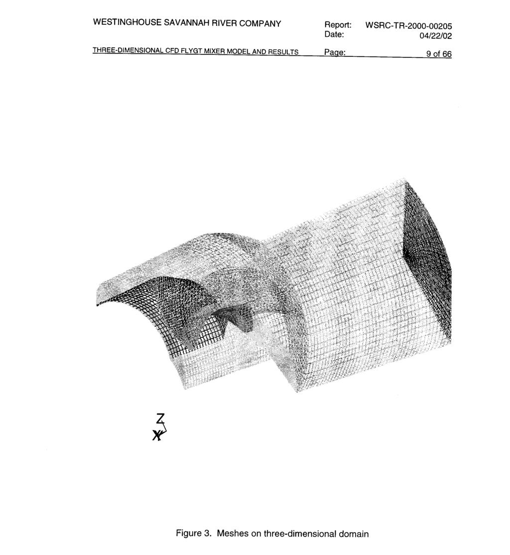
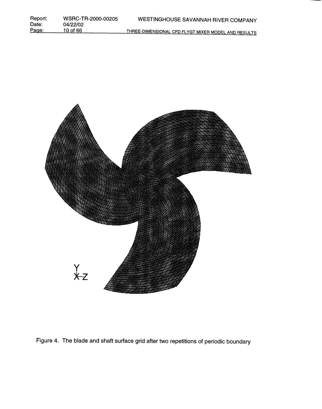
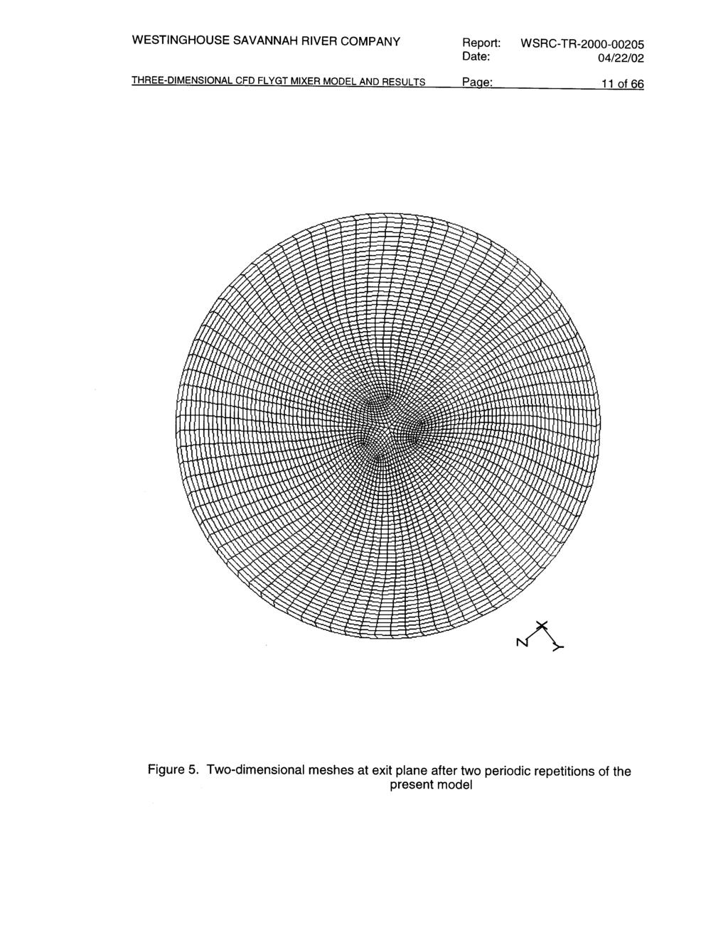
17 WESTINGHOUSE SAVANNAH RIVER COMPANY Report: WSRC-TR Date: 04/22/02 THREE-DIMENSIONAL CFD FLYGT MIXER MODEL AND RESULTS Page: 3 of 66 design guidance concerning the operation performance of a modified mixer, and this estimated loading information would be used as input to assess the structural vibration and stress analysis of the FLYGT mixer. Table 1. Modeling purpose and descriptions for Tank 19 FLYGT mixer. Model Brief description Primary purpose Status Axisymmetric 2-D model Shroud model using two-dimensional CFD approach To assess the impact of shroud length on discharge flow behavior for various boundary conditions Done (Ref. 8) 2-D wall jet model Two-dimensional wall jet model with the pump shroud submerged in 4ft tank level To investigate asymmetric effect of the liquid discharge from the optimum length of shroud due to the presence of the tank bottom Done (Ref. 8) 3-D FLYGT mixer model Steadystate model Detailed threedimensional pump model with prototypic propeller blade shape to exclude cavitation model To assess pump flow performance in detail and to evaluate load on propeller blade, hub, and pump shroud in a steady-state operation Present analysis Transient model Detailed threedimensional pump model with prototypic propeller blade shape to include cavitation model To evaluate transient load on propeller blade, hub, and pump shroud and to estimate transient time to reach steady-state mode Present analysis 2. Model Descriptions and Solution Methods Two CFD models have been developed to examine the flow performance of the modified Tank 19 FLYGT mixer (Lee and Dimenna, 2000) and to conduct sensitivity analysis for a wide range of possible boundary conditions. The modeling purpose and brief descriptions for the models are provided in Table 1. The methodology used for the models and analysis of the FLYGT mixer are shown in Fig. 1. The computational domain for the mixer model consists of three major regions, which are the propeller region, the inlet region upstream of the propeller, and the shroud region downstream of the propeller. The present modeling boundary is shown in Fig. 2. For computational efficiency, a 120 o sector of the mixer was used as a computational domain by using the following assumptions: - The blades of the propeller are perfectly balanced and symmetrical.
18 Report: WSRC-TR WESTINGHOUSE SAVANNAH RIVER COMPANY Date: 04/22/02 Page: 4 of 66 THREE-DIMENSIONAL CFD FLYGT MIXER MODEL AND RESULTS - The clearance gap between the tip of the blade and the shroud wall is kept constant. - The inlet geometry is symmetrical in terms of geometry and flow distribution in an azimuthal direction. - The flow distribution around the FLYGT mixer is fully mixed so that the wall boundary of the tank bottom has no impact on flow pattern just outside the shroud wall. About 120,000 mesh nodes were established from the mesh sensitivity analysis on a Silicon Graphics, Inc. (SGI) workstation platform. The computational meshes on a threedimensional domain are shown in Fig. 3. It should be noted that both curved-side surfaces of the 120 o model were used as periodic boundaries for a rotational reference frame. Two repetitions of the periodic boundaries result in a complete FLYGT mixer as shown in Figs. 4 and 5. For better convergence in numerical iterations, hexahedral meshes and smooth propagation of mesh size were adapted along the fluid-stream direction as shown in Fig. 5. The models assume isothermal conditions fixed at room temperature; the thermal effect on the performance of the pump is not calculated. One of the two models is a steady-state pump model assuming the fluid is incompressible and is not affected by cavitation. The other one is a transient cavitation model to investigate effects of density change due to the cavitating fluid for high-speed rotation of propeller. As the fluid jet emerges from the tip of propeller blade, the boundary layer separates at the cavity created near the leading-edge of the blade. Then, it rolls up and produces the cavitation cloud. Reynolds number for one typical flow (corresponding to about 9,000 gpm) of potential conditions, as shown in Table 2, is about 1.4 x 10 6 based on shroud diameter (D = m) and water at room temperature. That is, Dρ u Re = = 1.4 x 10 6 (1) µ The flow condition is in the fully-turbulent flow region. A standard k-ε turbulent model, namely, a two-equation model, was used for the present analysis. A velocity boundary condition was used at the shroud inlet. At the exit, a pressure boundary condition was used to determine flow pattern. The wall boundary of the shroud region used a no-slip boundary condition. The steady-state model used mass continuity and three standard momentum equations with addition of Coriolis force to the convection term considering the rotating reference frame. In this situtation, relative velocity becomes r v r r r r = v Ωxr where Ω r = angular velocity of the rotating frame and r r = position vector in the rotating frame. After some manipulation of the standard Navier-Stokes equation using equation (2), the convection term ( ( ρv r v r )) on the left-hand side of the momentum equation in a rotating frame of reference becomes (2)
19 WESTINGHOUSE SAVANNAH RIVER COMPANY Report: WSRC-TR Date: 04/22/02 THREE-DIMENSIONAL CFD FLYGT MIXER MODEL AND RESULTS Page: 5 of 66 r r r r r r r ( ρv v ) + 2ρΩ xv + ρω x ( Ω xr ) r r r (3) Equation (3) shows that two new terms, referred to as Coriolis force and centrifugal force, respectively, in the literature, are added to the standard convection term for the rotational effect. The transient cavitation model relies on the volume fraction concept so that it allows the fluids to be interpenetrating. The volume fraction of vapor phase created from the cavitation can therefore be equal to any value between 0 and 1, depending on the space occupied by vapor and liquid phases. The cavitation model allows mass to be transferred from one phase to another. This allows for modeling the formation of vapor from a liquid when fluid is cavitated. The model assumes no collapses of bubbles inside the shroud region and no slip between the two phases of the fluid because bubble residence time within the shroud is very short and bubbly flow regime is assumed to be dominant in the modeling domain. Thus, FLUENT solves a single-phase momentum equation for both phases and a volume fraction equation for the second phase. The volume fraction for the secondary vapor phase is determined from the continuity relation with interphase mass transfer from liquid to vapor phases. To get interphase mass transfer term, the change in bubble radius can be computed by a simplified Rayleigh equation assuming that the pressure within the bubble remains nearly constant when cavitation bubbles form in a liquid at room temperature. The latent heat of vaporization is neglected in isothermal cavitating flow. Bubble growth due to inertia effects is assumed negligible compared to caviation pressure. In this situation, bubble radius R at time t is determined by the following equation (Kubota et al., 1992): dr dt 2 = 0. 5 ( p g p) 3ρ f (4) where p g is vapor pressure corresponding to fluid temperature and ρ f is the density of the liquid. The total vapor mass (m g ) can be written as m g 4 = ρ g π 3 R n 3 (5) where n is the number of bubbles per unit volume. Bubble number density (n) in eq. (5) was assumed to be constant. For the present work, n was chosen as 1.0 x 10 4 m -3 from the literature (Kubota el al. (1992)). After some algebraic manipulation of eq. (5), rate of vapor formation due to cavitation can be written in terms of void fraction (α g ) as
20 Report: WSRC-TR WESTINGHOUSE SAVANNAH RIVER COMPANY Date: 04/22/02 Page: 6 of 66 THREE-DIMENSIONAL CFD FLYGT MIXER MODEL AND RESULTS dmg 3ρ 3 g 4πR dr = n dt R 3 dt (6) 3ρ gα g dr = R dt Thus, an equation for the interphase mass transfer (m fg ) due to cavitation can be obtained from eqs. (4) and (6). That is, m fg dm = dt g = 3ρgα R g ( p p) g 3ρ f (7) Equation (7) is used in the continuity equation for the vapor phase, which is created from the cavitation phenomenon of the high-speed mixing pump. Computations use the FLUENT rotating reference frame assumption in which the threedimensional flow field rotates in a reference frame that is fixed on the propeller blade. When equations of motion are solved in the steady-rotating reference frame, the Coriolis force term is added to the fluid acceleration term in the left-hand side of the Reynolds- Averaged Navier-Stokes equations derived in the inertial frame. The three-dimensional incompressible Navier-Stokes flow solver developed by Fluent, Inc. is applied to compute the rotating propeller flow in Tank 19 FLYGT mixer. The FLUENT solver is based on segregated solution method as shown in Fig. 6. HLW test data 2-D axisymmetr ic model O perating con diti ons for the present model Optim um shroud leng th Detailed 3-D FLYGT mixer m odel (including cavitation e ffect) Fluen t p ropeller m od el based on dig itized propeller shape data of Tank 19 FLYGT m ixer 2-D wall jet model A ssessment of fl ow perfor manc e in a 4 ft tank level Figure 1. Analysis methodology for FLYGT mixer models
21 WESTINGHOUSE SAVANNAH RIVER COMPANY Report: WSRC-TR Date: 04/22/02 THREE-DIMENSIONAL CFD FLYGT MIXER MODEL AND RESULTS Page: 7 of 66 r go u d i s n P e e t M r d l n n a y 3 / 1 6 " G a p Cl e a ra n c e Mo oo s n Figure 2. Modeling boundary for three-dimensional FLYGT mixer model Pump Propeller 2 " A n n u l a r G a p e h m e o i I l t R g n Pu p S rou d
22 Report: WSRC-TR WESTINGHOUSE SAVANNAH RIVER COMPANY Date: 04/22/02 Page: 8 of 66 THREE-DIMENSIONAL CFD FLYGT MIXER MODEL AND RESULTS Table 2. Potential ranges of flow conditions for Tank 19 FLYGT mixer Flowrate Flowrate Mass flow Inlet flow area Total flow area Inlet velocity Average Velocity* (gpm) (m 3 /sec) (kg/sec) Radial (m 2 ) annular (m 2 ) (m 2 ) (m/sec) (m/sec) (ft/sec) Note: * Average velocity was based on the cross-sectional flow area of the shroud.
23
24
25
26
27
28
29
30
31
32
33
34 Report: WSRC-TR WESTINGHOUSE SAVANNAH RIVER COMPANY Date: 04/22/02 Page: 20 of 66 THREE-DIMENSIONAL CFD FLYGT MIXER MODEL AND RESULTS 4. Results and Discussions The results characterizing the overall flow behavior seen in the present calculations using the detailed three-dimensional CFD model with a prototypic propeller shape show a reasonably good representation of turbulent flow behavior. The three-dimensional computational domain and boundary for the model is shown in Fig. 1. The standard k-ε model was used to capture the turbulent flow behavior of the FLYGT mixer. The flow velocity at the inlet of the mixer was about 3.3 ft/sec corresponding to 9,000 gpm flow as shown in Table 2. The inlet velocity was computed by assuming uniform flow distribution over the inlet geometry. The motor housing represents a flow blockage in the inlet region. Rotational effects of the pump propeller and hub regions were modeled by using the moving reference frame. The Reynolds number (Re) at the inlet is about 1.4 x 10 6 for liquid water at room temperature, which corresponds to the fully-turbulent flow regime. Pressures shown in all contour plots of this report should be considered as gauge pressure with respect to one atmospheric pressure unless there is any description about the pressure. 4.1 Steady-State Results All steady-state calculations were performed for turbulent flow using 120-deg symmetry and an unstructured mesh under a rotating reference frame. The turbulence effect in the model was represented by a two-equation model, standard κ-ε model. The calculations have been performed under steady-state conditions to evaluate the loads on the propeller, hub, and shroud regions of the mixer under the operating flow conditions of 9,000 to 19,000 gpm. In addition, the steady-state model has been used to examine how sensitive the pump flow performance or cavitation phenomenon associated with deterioration of the pump performance is to a change of operating parameters or conditions. In this model, the density change due to pump cavitation was not considered. The main operating parameters used in the present analysis are rotational speed of the propeller, pump flowrate, flow profile entering the pump propeller, and surface roughness of shroud wall. As mentioned earlier, the nominal operating flow condition was estimated by the steadystate CFD model using the HLW data (Adkins, 2000) measured at the shroud exit. From the present analysis and the literature, it is noted that pump cavitation is closely related to the pump performance in terms of performance deterioration and structural stability. The results showed that most cavitation occurred near the leading-edge tip of the pump blade as shown in Fig. 13. As shown in the figure, the lowest pressure is in the upstream region of the propeller blade causing the cavitation, while the highest pressure is in the downstream region of the blade. Table 3 shows minimum and maximum pressures around the leading tip of the propeller blade. The pressure difference across the leadingedge tip of the blade was about 38 psi for 860 rpm rotational speed as shown in Table 3. This is consistent with the literature data on the blade tips of ships propellers. In the literature, this type of cavitation is often referred to as tip cavitation. Thus, this cavitation is caused by vorticity shed into the flow field just downstream of the blade tip. The results in Table 3 shows that cavitation doesn t occur when pump speed is lower than 500 rpm. Figure 14 shows typical flow pattern and vorticity distributions near the downstream and upstream regions of the leading tip of the propeller blade. Maximum radial velocity
35 WESTINGHOUSE SAVANNAH RIVER COMPANY Report: WSRC-TR Date: 04/22/02 THREE-DIMENSIONAL CFD FLYGT MIXER MODEL AND RESULTS Page: 21 of 66 occurred near the tip of the blade. Table 4 shows maximum radial and axial velocities for various pump speeds at the leading-edge tip of the propeller blade for nominal operating flow condition (9,000 gpm). In this situation, maximum flowrate was artificially kept constant for different pump speeds for the simulation of performance deterioration. When pump speed increased under the condition of flow constraint, radial velocity at the blade tip increased quickly, but maximum axial velocity was not changed as expected. Vorticity is a measure of the instantaneous rotation rate of the fluid on the principal axes. The vorticity (ϖ r ) is defined as ϖ r = x v r (8) The usefulness of vorticity in interpreting fluid flow patterns is that vorticity tracks only the effects of viscous force. This can be seen by noting that the viscous term in the momentum equation of incompressible flow can be written as τ = µ 2 r r v = µ xϖ (9) Thus, unbalanced shear stress (τ) generates vorticity. Pressure forces and gravity forces in the momentum equation act through the center of mass of a particle and can not produce vorticity. Under a steady-state flow condition, loads on pump blades, hub, and shroud have been estimated by the present CFD pump model for a wide rage of flowrates and pump speeds. All the results are shown in Table 5. The results showed that pressure force was dominant compared to viscous force. For a given flowrate, total load for each of the three regions increased rapidly as pump speed increased. Table 3. Pressures near the leading-edge tip of the pump blade under 9,000 gpm water flowrate of steady-state operating condition (Water saturation pressure corresponding to room temperature is about psig.). Pump speed 500 rpm 600 rpm 700 rpm 860 rpm Upstream pressure psig psig psig psig Downstream pressure 4.6 psig 4.6 psig 4.7 psig 9.4 psig Table 4. Maximum axial and radial velocities for various pump speeds at the leading-edge tip of the pump blade under 9,000 gpm flow constraint of steady-state condition. Pump speed 500 rpm 600 rpm 700 rpm 860 rpm Max. radial velocity 5.6 m/sec 6.8 m/sec 8.1 m/sec 11.1 m/sec Max. axial velocity 10.5 m/sec 10.6 m/sec 10.8 m/sec 10.8 m/sec
36 Report: WSRC-TR WESTINGHOUSE SAVANNAH RIVER COMPANY Date: 04/22/02 Page: 22 of 66 THREE-DIMENSIONAL CFD FLYGT MIXER MODEL AND RESULTS Changes in flowrate are harder to interpret because the flowrate was used a boundary condition for the calculation. As the flowrate was decreased for a given pump speed, the propeller became starved for flow. Cavitation increased and the pressure loads on the mixer components increased. All of this indicated a deterioration in pump performance with reduced flow. As shown in Fig. 15, load for the propeller blade is the largest among the three regions. It is noted that load for each component is not sensitive to the pump flowrate. Figure 16 shows that radial velocity at the tip of the blade is very sensitive to the rotational speed of the mixer. When pump speed increased from 500 to 860 rpm, maximum radial speed increased from 5.6 m/sec to 11.1 m/sec as shown in Table 4. Static pressure distributions corresponding to the velocity distributions are quite different depending on rotational speed of the mixing pump as presented in Fig. 17. These pressure distributions induce the load for each component of the mixer. As expected from our intuition, a large and localized vortex motion is generated near the leading-edge tip of the propeller blade. This large vortex motion introduces the cavitation, referred to as vortex cavitation in the literature (Knapp et al., 1970). Vorticity contour plots for the plane crossing the tip of the blade are shown in Fig. 18. The pressure coefficient along the axial flow direction crossing the leading-edge tip of the blade, as shown in fig. 19, indicates that the location of the minimum pressure is very close to the tip of the blade. This implies that the vortex cavitation inception will occur near the tip of the blade. It is seen that the negative minimum pressure coefficient (- C p,min ) increases as the pump speed increases and the corresponding advance coefficient decreases, i.e., the propeller loading is increased. Comparisons of the numerical results for a wide range of non-dimensional pump speeds are summarized in Table 6. The advance coefficient J is a dimensionless number associated with the propeller design condition, which is the ratio of fluid average velocity (u avg ) to the product of pump speed (n) and propeller diameter (D prop ), that is, J = u avg /(n D prop ). These results are consistent with the literature data (Hsiao and Pauley, 1999). The pressure coefficient (C p ) is a dimensionless parameter defined by the reference pressure (P ref ) and the reference dynamic pressure (Q ref ). That is, C p = ( P P ) Q ref ref (10) In eq. (5), Q ref is defined in terms of the reference velocity (V ref ). Q ref = ρ fvref (11) In Table 6 and Fig. 19, one atmospheric pressure and 6 m/sec flow conditions were used as the reference values. The results shown in Fig. 19 indicate that cavitation occurs near the leading-edge tip of the blade for the 700 and 860 rpm pump speeds, but it does not occur for the 500 rpm speed. The 600 rpm pump speed is the critical value for the cavitation to occur. Thus, pump speed should be decreased from 860 rpm to about 500 rpm, which is close to the original design speed 440 rpm of the FLYGT mixer, if cavitation needs to be avoided for the structural vibration or stability of the mixer. The cavitation line shown in the figure is based on the saturation pressure of vapor corresponding to the room temperature water, although real flow effects such as random turbulent fluctuation and water quality are known to influence cavitation inception. Figure 20 shows the
37 WESTINGHOUSE SAVANNAH RIVER COMPANY Report: WSRC-TR Date: 04/22/02 THREE-DIMENSIONAL CFD FLYGT MIXER MODEL AND RESULTS Page: 23 of 66 distributions of the fluid vorticity, defined by eq. (8), along the axial direction crossing the tip of the blade. It is noted that there are two peaks. The first peak occurs near the tip trailing edge, and the second one is dominant near the leading-edge tip of the blade. These results are consistent with the literature observations (Knapp et al., 1970). Turbulence intensity contour plots at the plane of the leading-edge tip are shown for three different rotational speeds of the FLYGT mixer in Fig. 21. The turbulence intensity is defined as the ratio of the root-mean-square of the velocity fluctuations, u, to the mean flow velocity, u avg. When pump speed increases from 600 rpm to 860 rpm under 9,000 gpm of nominal flow condition, the turbulence intensity changes from 34% up to 50% as shown in Fig. 21 (note that color scales change for each plot.). As discussed earlier, the present model consists of three major regions as a modeling domain. They are propeller blade, hub (shaft region), and shroud regions. Under the steady-state model, phase change is not allowed even for the cavitating situation near the tip of the blade. However, the transient model allows phase change of liquid fluid when system pressure is below the vapor pressure corresponding to the fluid temperature. Detailed static pressure distributions at the downstream region of the blade are shown in Fig. 22. Highest pressure is at the downstream side of the leading-edge tip of the propeller blade, but lowest pressure is at the upstream side of the blade tip as discussed earlier. Figure 22 shows the viscous shear stress contour plot on the blade surface. Typical flow pattern near the propeller region for 9,000 gpm nominal flow and 860 rpm pump speed is presented in Fig. 24. Flow is entering the propeller zone in a convergent way and then reaches maximum velocity in the radial direction at the tip of the propeller blade. After leaving the propeller region the fluid flows in a divergent direction. Near the leading tip region of the propeller a large local vortex was generated, which is consistent with the experimental observation in the literature (Knapp et al., 1970). Vorticity contour plot near the blade of the propeller is shown in Fig. 25. Vorticity contour plot near the hub zone of the propeller is presented in Fig. 26. Highest vortex was produced near the blade connection region of the hub. Static pressure and shear stress distributions corresponding to the vorticity distribution of Fig. 26 are shown in Figs. 27 and 28. Cavitation at the shroud wall was greatest near the upstream region of the propeller, while compression occurred most near the downstream region of the propeller. Graphical results for static pressure and shear stress distributions are shown in Figs. 29 and 30. Velocity at the exit of the pump shroud is important in the assessment of the pump performance in terms of mixing capability. In the present work a wide range of pump flow and operating conditions were performed by using the three-dimensional pump model with the FLYGT mixer propeller model. Results of the radial velocity distributions at the shroud exit are shown in Fig. 31. The results showed that the location of the peak velocity moved to the peripheral region with decreasing pump flow. A backflow region due to flow reversal near the center of the shroud increased with decreasing flow. Figure 32 shows threedimensional steady-state velocity vector plots for 860 rpm and 12,000 gpm flow condition at the inlet and exit regions of the pump shroud. It should be noted that velocity near the center of the shroud are much lower than the peripheral velocity at the plane of the shroud exit. This is consistent with the HLW test data (Adkins, 2000).
38 Report: WSRC-TR WESTINGHOUSE SAVANNAH RIVER COMPANY Date: 04/22/02 Page: 24 of 66 THREE-DIMENSIONAL CFD FLYGT MIXER MODEL AND RESULTS Table 5. Axial forces along the flow direction for propeller, hub, and shroud regions under wide range of steady-state pump operating conditions. Pump operating conditions Propeller region Hub region Shroud wall region Pump flowrate (gpm) Pump speed (rpm) Pressure (N) Viscous (N) Pressure (N) Viscous (N) Pressure (N) Viscous (N) , , , ,000 19, (Note: Conversion factor 1 pound-force = 4.448N) Table 6. Comparison of minimum pressure coefficients (C p,min ) for the advance coefficients (J) corresponding to various rotational pump speeds. Pump speed (rpm) J (---) Reynolds number (---) - C p,min (---) Total loading on the blades (pound-force) x x x x x
39
40
41
42
43
44
45
46
47
48
49
50
51
52
53
54
55
56
57
58
59 WESTINGHOUSE SAVANNAH RIVER COMPANY Report: WSRC-TR Date: 04/22/02 THREE-DIMENSIONAL CFD FLYGT MIXER MODEL AND RESULTS Page: 45 of Sensitivity Run Results Sensitivity runs were performed by using the steady-state three-dimensional CFD model. The primary purpose is to investigate what physical parameters have the most impact on operating performance and system stability of the FLYGT mixer. From the steady-state model results, physical parameters such as inlet flow conditions, shroud wall roughness, and rotational speed of pump were chosen for the sensitivity studies. - Non-uniform Inlet Flow Condition This situation was simulated to examine the impact on the shroud exit velocity of nonuniform inlet velocity for the flow blockage caused by the motor housing upstream of the pump propeller. Non-uniform velocity was tested with an assumption that velocity around motor housing increased linearly along the flow direction toward the propeller region. That is, 1 A 2 u avg = u A r ( x) 1 1 A x = L L x= 0 in = in ( α + βx) da dx (10) Constants α and β in the above integral, eq. (10), were determined by using the boundary condition u r (x = 0 ) = 0 and the flow continuity Q(total volumetric flowrate) = u avg A. u avg is area-averaged radial velocity at the inlet of the mixer. The area-averaged speeds for potential flow conditions are shown in Table 2. Detailed flow direction and notations used in the above equation are shown in Fig. 33. This non-uniform condition was based on the assumption that azimuthal velocity gradients at both sides of the symmetry planes in 120 o sector geometry of the mixer, as shown in Fig. 3, are zero. For these studies, typical operating conditions were chosen as two different operating flows (9,000 and 12,000 gpm) with 860 rpm pump speed. The results showed that at shroud exit radial flow distributions for non-uniform inlet condition is a little bit more uniform than those of uniform inlet flow condition. The sensitivity results are shown in Fig. 34. Total loads for the three components of the mixer with non-uniform inlet flow are about 7% lower than those of uniform inlet flow for the operating conditions of 12,000 gpm flow with 860 rpm pump speed. Three-dimensional velocity flow pattern near the inlet and the shroud exit regions is shown in Fig. 35. However, for 9,000 gpm pump flow with 860 rpm pump speed, loads for non-uniform inlet flow are close to those of uniform inlet flow. The detailed comparison of the two cases is shown in Table 7.
60
61
62
63
64
65

66
67
68
69
70
71
72
73
74
75
76
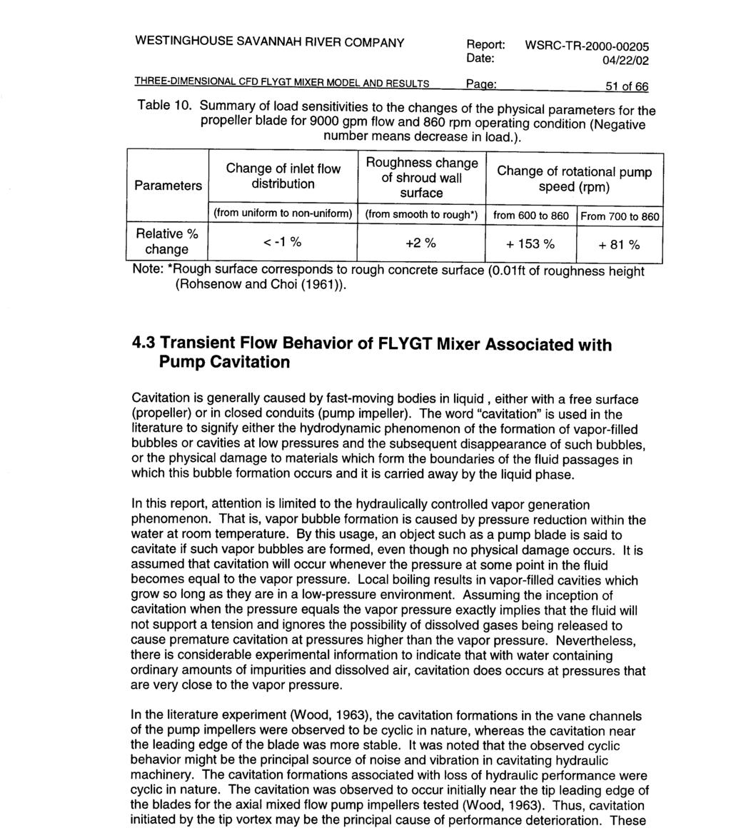
77 WESTINGHOUSE SAVANNAH RIVER COMPANY Report: WSRC-TR Date: 04/22/02 THREE-DIMENSIONAL CFD FLYGT MIXER MODEL AND RESULTS Page: 63 of Conclusions The present analysis took two modeling approaches with a Computational Fluid Dynamics (CFD) method. They are steady-state pump model and transient cavitation model considering density change effect due to local cavitation. The computations were performed for a three-dimensional detailed model of the FLYGT mixer with the prototypic propeller shape. The models mainly include propeller region, inlet region upstream of the propeller, and downstream shroud region as a computational domain. The general characteristics of the propeller flow including the blade-to-blade rotational flow, cavitation with tip vortex, and flow pattern at shroud exit were well predicted by the present CFD method using computational domain of one-third FLYGT mixer for better computational efficiency. From the analysis results for the three-dimensional models of the Tank 19 FLYGT mixer, the following conclusions are drawn: 1. Nominal operating conditions were measured by the pitot-tube test data (Adkins, 2000). Comparisons with calculated results showed that nominal pump flow conditions were about 9000 gpm, and pump flow distribution was not sensitive to rotational speed of the mixer (600 to 860 rpm), which is consistent with the test data. 2. From the results of the present detailed model and the previous wall jet model, the pump with a 20 long modified shroud showed reasonable flow performance at the exit of the shroud in terms of backflow prevention and mixing capability. 3. The detailed steady-state model results showed that load for each of the three major component (propeller blade, hub and shroud) of the mixer increased as speed of the mixer increased. It was noted that cavitation occurred near the leading-tip of the pump blade and the degree of cavitation increased rapidly with pump speed increase. 4. The steady-state results show that cavitation doesn t occur for 9,000 gpm flowrate when the pump speed is lower than 500 rpm. This is consistent with the original blade design of the FLYGT mixer to avoid the cavitation. The original design speed was 440 rpm. 5. From the sensitivity study, it was noted that the pump speed was a sensitive parameter for the load for each pump component, but it was not sensitive for the pump flow performance. The propeller blade has the largest load among the three components of the FLYGT mixer under a wide range of pump operating conditions. 6. The transient results showed that transient pump behaviors such as change of fluid density and loadings of mixer were developed to steady-state conditions within about 1 second, corresponding to about 40 cycles of the propeller blade after the initiation of the pump cavitation. In addition, a low density region was established near the peripheral region adjacent to the shroud wall because all bubbles generated as a result of cavitation migrated to the high-velocity fluid region near the tip of the blade.
78 Report: WSRC-TR WESTINGHOUSE SAVANNAH RIVER COMPANY Date: 04/22/02 Page: 64 of 66 THREE-DIMENSIONAL CFD FLYGT MIXER MODEL AND RESULTS 6. Recommendations From the detailed model and the previous two-dimensional wall jet model, it was noted that the pump speed could be decreased without reducing the flow performance of the mixer under the current 20 single-piece machined shroud. From the present steady-state results, it is recommended that the pump speed decrease from 860 rpm down to about 500 rpm when cavitation needs to be avoided for better pump performance. The present model used azimuthal symmetrical assumption at the inlet region. One third of the mixer was modeled by using symmetrical planes at both-end sides of the model for computational efficiency. Thus, the present model can not predict non-uniform inlet flow condition in an azimuthal direction. In reality, non-uniform water flow and air entrained by a vortex at the inlet region may cause periodical choking before entering the propeller region. It is recommended that the current 120 o symmetry, single-blade model be extended to a three-blade mixer with the tank bottom and free liquid surface (about 4ft level) included in the full three-dimensional computation domain. Thus, boundary conditions at the pump inlet for the CFD model would be closer to the real situation, which is non-uniform flow distribution at the screen inlet due to the flow blockage and due to the presence of the tank bottom. This change would allow us to: 1. Remove the fixed flow boundary condition at the pump inlet. 2. Analyze pump performance as a function of operating speed. 3. Determine the optimum operating point for the existing propeller shape. This model could also simulate three-dimensional axial flow dissipation after the shroud exit above the tank bottom to assess mixing performance. The current two-dimensional jet model has been used to estimate this performance, but it can not capture the physics of three-dimensional swirling phenomena.
EVALUATION OF SLUDGE REMOVAL CAPABILITIES FOR ADMP MIXER IN TANK 18
 WSRC-TR-2003-00166 KEYWORDS: Sludge Suspension Computational Approach Sludge Mixing Jet Flow Model Mixing Pump Model RETENTION - Permanent EVALUATION OF SLUDGE REMOVAL CAPABILITIES FOR ADMP MIXER IN TANK
Slurry Pump Mixing Effectiveness in Tank 50H
 WSRC-STI-2008-00151 Si Young Lee and Richard A. Dimenna February 2008 Washington Savannah River Company Savannah River National Laboratory Aiken, SC 29808 Prepared for the U.S. Department of Energy Under
August 3,1999. Stiffness and Strength Properties for Basic Sandwich Material Core Types UCRL-JC B. Kim, R.M. Christensen.
 Preprint UCRL-JC-135347 Stiffness and Strength Properties for Basic Sandwich Material Core Types B. Kim, R.M. Christensen This article was submitted to ASME IMECE 99, Nashville, TN, November 14-19, 1999
EROSION ANALYSIS FOR THE MISALIGNED U2 NOZZLE AND ITS CONNECTOR BLOCK
 WSRC-TR-2002-00352 EROSION ANALYSIS FOR THE MISALIGNED U2 NOZZLE AND ITS CONNECTOR BLOCK Si Young Lee and Richard A. Dimenna Westinghouse Savannah River Company Savannah River Site Aiken, SC 29808 Prepared
Fluid Dynamics Exercises and questions for the course
 Fluid Dynamics Exercises and questions for the course January 15, 2014 A two dimensional flow field characterised by the following velocity components in polar coordinates is called a free vortex: u r
Keywords - Gas Turbine, Exhaust Diffuser, Annular Diffuser, CFD, Numerical Simulations.
 Numerical Investigations of PGT10 Gas Turbine Exhaust Diffuser Using Hexahedral Dominant Grid Vaddin Chetan, D V Satish, Dr. Prakash S Kulkarni Department of Mechanical Engineering, VVCE, Mysore, Department
Manhar Dhanak Florida Atlantic University Graduate Student: Zaqie Reza
 REPRESENTING PRESENCE OF SUBSURFACE CURRENT TURBINES IN OCEAN MODELS Manhar Dhanak Florida Atlantic University Graduate Student: Zaqie Reza 1 Momentum Equations 2 Effect of inclusion of Coriolis force
Flow analysis in centrifugal compressor vaneless diffusers
 348 Journal of Scientific & Industrial Research J SCI IND RES VOL 67 MAY 2008 Vol. 67, May 2008, pp. 348-354 Flow analysis in centrifugal compressor vaneless diffusers Ozturk Tatar, Adnan Ozturk and Ali
GA A22689 SLOW LINER FUSION
 GA A22689 SLOW LINER FUSION by AUGUST 1997 DISCLAIMER This report was prepared as an account of work sponsored by an agency of the United States Government. Neither the United States Government nor any
MAGNETICALLY CONTROLLED DEPOSITION OF METALS USING GAS PLASMA. Quarterly Progress Report April - June 1997
 MAGNETICALLY CONTROLLED DEPOSITION OF METALS USING GAS PLASMA Quarterly Progress Report April - June 1997 DISCLAIMER This report was prepared as an account of work sponsored by an agency of the United
FLOW PATTERN STUDY OF A CENTRIFUGAL PUMP USING CFD METHODS CONCENTRATING ON VOLUTE TONGUE ROLE
 FLOW PATTERN STUDY OF A CENTRIFUGAL PUMP USING CFD METHODS CONCENTRATING ON VOLUTE TONGUE ROLE N. Pourmahmoud and S. Majid Taleby Faculty of Engineering, Urmia University, Urmia, Iran E-Mail: majid.taleby@gmail.com
Development of a Parallel, 3D, Lattice Boltzmann Method CFD Solver for Simulation of Turbulent Reactor Flow
 DOE-FIU SCIENCE & TECHNOLOGY WORKFORCE DEVELOPMENT PROGRAM STUDENT SUMMER INTERNSHIP TECHNICAL REPORT June 4, 2012 to August 10, 2012 Development of a Parallel, 3D, Lattice Boltzmann Method CFD Solver
Development of a High Intensity EBIT for Basic and Applied Science
 UCRL-ID- 129832 Development of a High Intensity EBIT for Basic and Applied Science R.E. Marrs D. Schneider February 5,1998 This is an informal report intended primarily for internal or limited external
DESIGN AND CFD ANALYSIS OF A CENTRIFUGAL PUMP
 DESIGN AND CFD ANALYSIS OF A CENTRIFUGAL PUMP 1 CH.YADAGIRI, 2 P.VIJAYANAND 1 Pg Scholar, Department of MECH, Holymary Institute of Technology, Ranga Reddy, Telangana, India. 2 Assistant Professor, Department
DEVELOPMENT OF CFD MODEL FOR A SWIRL STABILIZED SPRAY COMBUSTOR
 DRAFT Proceedings of ASME IMECE: International Mechanical Engineering Conference & Exposition Chicago, Illinois Nov. 5-10, 2006 IMECE2006-14867 DEVELOPMENT OF CFD MODEL FOR A SWIRL STABILIZED SPRAY COMBUSTOR
Application of a Three-Dimensional Prognostic Model During the ETEX Real-Time Modeling Exercise: Evaluatin of Results (u)
") WSRC-MS-96-0766 COdF- 9 7 0 9 1 9 m - 9 Application of a Three-Dimensional Prognostic Model During the ETEX Real-Time Modeling Exercise: Evaluatin of Results (u) by D. P. Griggs Westinghouse Savannah River
WSRC-MS-96-0766 COdF- 9 7 0 9 1 9 m - 9 Application of a Three-Dimensional Prognostic Model During the ETEX Real-Time Modeling Exercise: Evaluatin of Results (u) by D. P. Griggs Westinghouse Savannah River
CHAPTER 7 NUMERICAL MODELLING OF A SPIRAL HEAT EXCHANGER USING CFD TECHNIQUE
 CHAPTER 7 NUMERICAL MODELLING OF A SPIRAL HEAT EXCHANGER USING CFD TECHNIQUE In this chapter, the governing equations for the proposed numerical model with discretisation methods are presented. Spiral
HEAT TRANSFER AND THERMAL STRESS ANALYSES OF A GLASS BEAM DUMP
 UCRL-D-122231 HEAT TRANSFER AND THERMAL STRESS ANALYSES OF A GLASS BEAM DUMP Virginia C. Garcia September 1995 This is an informal report intended primarily for internal or limited external distribution.
Centrifugal Destabilization and Restabilization of Plane Shear Flows
 Centrifugal Destabilization and Restabilization of Plane Shear Flows A. J. Conley Mathematics and Computer Science Division Argonne National Laboratory Argonne, L 60439 Abstract The flow of an incompressible
Simulation of Double-Null Divertor Plasmas with the UEDGE Code
 Preprint UCRL-JC-134341 Simulation of Double-Null Divertor Plasmas with the UEDGE Code M. E. Rensink, S. L. Allen, G. 0. Porter, T. 0. Rognlien This article was submitted to 7th International Workshop
The effect of rotational speed variation on the static pressure in the centrifugal pump (part 1)
") IOSR Journal of Mechanical and Civil Engineering (IOSR-JMCE) e-issn: 2278-1684,p-ISSN: 2320-334X, Volume 8, Issue 6 (Sep. - Oct. 2013), PP 83-94 The effect of rotational speed variation on the static pressure
IOSR Journal of Mechanical and Civil Engineering (IOSR-JMCE) e-issn: 2278-1684,p-ISSN: 2320-334X, Volume 8, Issue 6 (Sep. - Oct. 2013), PP 83-94 The effect of rotational speed variation on the static pressure
Performance characteristics of turbo blower in a refuse collecting system according to operation conditions
 Journal of Mechanical Science and Technology 22 (2008) 1896~1901 Journal of Mechanical Science and Technology www.springerlink.com/content/1738-494x DOI 10.1007/s12206-008-0729-6 Performance characteristics
Validation 3. Laminar Flow Around a Circular Cylinder
 Validation 3. Laminar Flow Around a Circular Cylinder 3.1 Introduction Steady and unsteady laminar flow behind a circular cylinder, representing flow around bluff bodies, has been subjected to numerous
Investigation of Flow Profile in Open Channels using CFD
 Investigation of Flow Profile in Open Channels using CFD B. K. Gandhi 1, H.K. Verma 2 and Boby Abraham 3 Abstract Accuracy of the efficiency measurement of a hydro-electric generating unit depends on the
Modeling Laser and e-beam Generated Plasma-Plume Experiments Using LASNEX
 UCRL-ID-136726 Modeling Laser and e-beam Generated Plasma-Plume Experiments Using LASNEX D.D.-M. Ho December 1,1999 US. Department of Energy Approved for public release; further dissemination unlimited
SRL TEE DRY DEPOSITION OF PARTICULATE MATTER ABOVE. Robert Lorenz and Charles E. Murphy, Jr.
 TEE DRY DEPOSITION OF PARTICULATE MATTER ABOVE A LOBLOLLY PI~ PLARTATIOR - by Robert Lorenz and Charles E Murphy, Jr E I du Pent de Nemours & Company Savannah River Laboratory Aiken, South Carolina 29808
Turbulent Scaling in Fluids. Robert Ecke, MST-10 Ning Li, MST-10 Shi-Yi Li, T-13 Yuanming Liu, MST-10
 Title: Author(s): Submitted to: Turbulent Scaling in Fluids Robert Ecke, MST-10 Ning Li, MST-10 Shi-Yi Li, T-13 Yuanming Liu, MST-10 RECEIVED OCT 3 I 1998 DOE Office of Scientific and Technical Information
Parametric Instabilities in Laser/Matter Interaction: From Noise Levels to Relativistic Regimes
 UCRL-ID-133227 Parametric Instabilities in Laser/Matter Interaction: From Noise Levels to Relativistic Regimes H. A. Baldis C. Labaune W. L. Kruer February 11, 1999 Lawrence Livermore National Laboratory
Removal of Uranium from Plutonium Solutions by Anion Exchange
 Removal of Uranium from Plutonium Solutions by Anion Exchange Tracy S. Rudisill and Jonathan M. Duffey February 2002 Westinghouse Savannah River Company Aiken, SC 29808 Prepared for the U. S. Department
TABLE OF CONTENTS CHAPTER TITLE PAGE
 v TABLE OF CONTENTS CHAPTER TITLE PAGE TABLE OF CONTENTS LIST OF TABLES LIST OF FIGURES LIST OF SYMBOLS LIST OF APPENDICES v viii ix xii xiv CHAPTER 1 INTRODUCTION 1.1 Introduction 1 1.2 Literature Review
GA A22677 THERMAL ANALYSIS AND TESTING FOR DIII D OHMIC HEATING COIL
 GA A677 THERMAL ANALYSIS AND TESTING FOR DIII D OHMIC HEATING COIL by C.B. BAXI, P.M. ANDERSON, and A.M. GOOTGELD NOVEMBER 1997 DISCLAIMER This report was prepared as an account of work sponsored by an
Interpreting Differential Equations of Transport Phenomena
 Interpreting Differential Equations of Transport Phenomena There are a number of techniques generally useful in interpreting and simplifying the mathematical description of physical problems. Here we introduce
FLOW CHARACTERISTICS IN A VOLUTE-TYPE CENTRIFUGAL PUMP USING LARGE EDDY SIMULATION
 FLOW CHARACTERISTICS IN A VOLUTE-TYPE CENTRIFUGAL PUMP USING LARGE EDDY SIMULATION Beomjun Kye Keuntae Park Department of Mechanical & Aerospace Engineering Department of Mechanical & Aerospace Engineering
COMPUTATIONAL FLOW ANALYSIS THROUGH A DOUBLE-SUCTION IMPELLER OF A CENTRIFUGAL PUMP
 Proceedings of the Fortieth National Conference on Fluid Mechanics and Fluid Power December 12-14, 2013, NIT Hamirpur, Himachal Pradesh, India FMFP2013_141 COMPUTATIONAL FLOW ANALYSIS THROUGH A DOUBLE-SUCTION
STRUCTURAL ANALYSIS OF A WESTFALL 2800 MIXER, BETA = 0.8 GFS R1. By Kimbal A. Hall, PE. Submitted to: WESTFALL MANUFACTURING COMPANY
 STRUCTURAL ANALYSIS OF A WESTFALL 2800 MIXER, BETA = 0.8 GFS-411519-1R1 By Kimbal A. Hall, PE Submitted to: WESTFALL MANUFACTURING COMPANY OCTOBER 2011 ALDEN RESEARCH LABORATORY, INC. 30 Shrewsbury Street
Effect of modification to tongue and basic circle diameter on vibration in a double-suction centrifugal pump
 5th International Conference on Information Engineering for Mechanics and Materials (ICIMM 2015) Effect of modification to tongue and basic circle diameter on vibration in a double-suction centrifugal
Basic Fluid Mechanics
 Basic Fluid Mechanics Chapter 6A: Internal Incompressible Viscous Flow 4/16/2018 C6A: Internal Incompressible Viscous Flow 1 6.1 Introduction For the present chapter we will limit our study to incompressible
10.52 Mechanics of Fluids Spring 2006 Problem Set 3
 10.52 Mechanics of Fluids Spring 2006 Problem Set 3 Problem 1 Mass transfer studies involving the transport of a solute from a gas to a liquid often involve the use of a laminar jet of liquid. The situation
PROJECT PROGRESS REPORT (03/lfi?lfibr-~/15/1998):
:") F?ECEVVEI) N% 05 w PROJECT PROGRESS REPORT (03/lfi?lfibr-~/15/1998): A COMPREHENSIVE STUDY OF FRACTURE PATTERNS AND DENSITIES IN THE GEYSERS GEOTHERMAL RESERVOIR USING MICROEARTHQUAKE SHEAR-WAVE SPLITTING
F?ECEVVEI) N% 05 w PROJECT PROGRESS REPORT (03/lfi?lfibr-~/15/1998): A COMPREHENSIVE STUDY OF FRACTURE PATTERNS AND DENSITIES IN THE GEYSERS GEOTHERMAL RESERVOIR USING MICROEARTHQUAKE SHEAR-WAVE SPLITTING
Lesson 6 Review of fundamentals: Fluid flow
 Lesson 6 Review of fundamentals: Fluid flow The specific objective of this lesson is to conduct a brief review of the fundamentals of fluid flow and present: A general equation for conservation of mass
V (r,t) = i ˆ u( x, y,z,t) + ˆ j v( x, y,z,t) + k ˆ w( x, y, z,t)
 = i ˆ u( x, y,z,t) + ˆ j v( x, y,z,t) + k ˆ w( x, y, z,t)") IV. DIFFERENTIAL RELATIONS FOR A FLUID PARTICLE This chapter presents the development and application of the basic differential equations of fluid motion. Simplifications in the general equations and common
IV. DIFFERENTIAL RELATIONS FOR A FLUID PARTICLE This chapter presents the development and application of the basic differential equations of fluid motion. Simplifications in the general equations and common
Ray M. Stringfield Robert J. Kares J. R. Thomas, Jr.
 U4JR-96-1107 * v TITLE: AU THOR(S): SUBMITTED TO: TEMPERATURE DISTRIBUTION IN A FLOWING FLUID HEATED IN A MICROWAVE RESONANT CAVI'W Eric M. Nelson Ray M. Stringfield Robert J. Kares J. R. Thomas, Jr. AOT-9
Numerical Investigation of Thermal Performance in Cross Flow Around Square Array of Circular Cylinders
 Numerical Investigation of Thermal Performance in Cross Flow Around Square Array of Circular Cylinders A. Jugal M. Panchal, B. A M Lakdawala 2 A. M. Tech student, Mechanical Engineering Department, Institute
EFFECT OF FORCED ROTATING VANELESS DIFFUSERS ON CENTRIFUGAL COMPRESSOR STAGE PERFORMANCE
 Journal of Engineering Science and Technology Vol. 6, No. 5 (2011) 558-574 School of Engineering, Taylor s University EFFECT OF FORCED ROTATING VANELESS DIFFUSERS ON CENTRIFUGAL COMPRESSOR STAGE PERFORMANCE
Turbulent Boundary Layers & Turbulence Models. Lecture 09
 Turbulent Boundary Layers & Turbulence Models Lecture 09 The turbulent boundary layer In turbulent flow, the boundary layer is defined as the thin region on the surface of a body in which viscous effects
International Journal of Scientific & Engineering Research, Volume 6, Issue 5, May ISSN
 International Journal of Scientific & Engineering Research, Volume 6, Issue 5, May-2015 28 CFD BASED HEAT TRANSFER ANALYSIS OF SOLAR AIR HEATER DUCT PROVIDED WITH ARTIFICIAL ROUGHNESS Vivek Rao, Dr. Ajay
Signature: (Note that unsigned exams will be given a score of zero.)
") Neatly print your name: Signature: (Note that unsigned exams will be given a score of zero.) Circle your lecture section (-1 point if not circled, or circled incorrectly): Prof. Dabiri Prof. Wassgren Prof.
Neatly print your name: Signature: (Note that unsigned exams will be given a score of zero.) Circle your lecture section (-1 point if not circled, or circled incorrectly): Prof. Dabiri Prof. Wassgren Prof.
EXPERIMENTAL AND COMPUTATIONAL STUDY OF A RADIAL FLOW PUMP IMPELLER
 nd International Conference From Scientific Computing to Computational Engineering nd IC-SCCE Athens, 5-8 July, 006 IC-SCCE EXPERIMENTAL AND COMPUTATIONAL STUDY OF A RADIAL FLOW PUMP IMPELLER Vasilios
Predictionof discharge coefficient of Venturimeter at low Reynolds numbers by analytical and CFD Method
 International Journal of Engineering and Technical Research (IJETR) ISSN: 2321-0869, Volume-3, Issue-5, May 2015 Predictionof discharge coefficient of Venturimeter at low Reynolds numbers by analytical
Effects of the Leakage Flow Tangential Velocity in Shrouded Axial Compressor Cascades *
 TSINGHUA SCIENCE AND TECHNOLOGY ISSNll1007-0214ll21/21llpp105-110 Volume 14, Number S2, December 2009 Effects of the Leakage Flow Tangential Velocity in Shrouded Axial Compressor Cascades * KIM Jinwook
Chapter 5 Control Volume Approach and Continuity Equation
 Chapter 5 Control Volume Approach and Continuity Equation Lagrangian and Eulerian Approach To evaluate the pressure and velocities at arbitrary locations in a flow field. The flow into a sudden contraction,
Advanced Gas Foil Bearing Design for Supercritical
 Advanced Gas Foil Bearing Design for Supercritical CO 2 Power Cycles Peter A. Chapman, Jr., P.E. Principal Engineer Mechanical Solutions, Inc. pac@mechsol.com Albany, NY Whippany, NJ Denver, CO www.mechsol.com
NUMERICAL STUDY OF THE EFFECT OF BLADE SZE ON PUMPING EFFECTIVENESS OF A PADDLE IMPELLER IN AN UNBAFFLED MIXING VESSEL
 Third International Conference on CFD in the Minerals and Process Industries CSIRO, Melbourne, Australia 10-12 December 2003 NUMERICAL STUDY OF THE EFFECT OF BLADE SZE ON PUMPING EFFECTIVENESS OF A PADDLE
Study on residence time distribution of CSTR using CFD
 Indian Journal of Chemical Technology Vol. 3, March 16, pp. 114-1 Study on residence time distribution of CSTR using CFD Akhilesh Khapre*, Divya Rajavathsavai & Basudeb Munshi Department of Chemical Engineering,
OAK RIDGE NATIONAL LABORATORY
 ORNL/TM-13339 OAK RDGE NATONAL LABORATORY 7+ A SMPLE ROTATONAL PENDULUM METHOD TO MEASURE THE RAD OF GYRATON OR MASS MOMENTS OF NERTA OF A ROTOR AND OTHER ASSEMBLES LOCKHEED M A R T N John B. Andriulli
GA A22722 CENTRAL THOMSON SCATTERING UPGRADE ON DIII D
 GA A22722 CENTRAL THOMSON SCATTERING UPGRADE ON DIII D by D.G. NILSON, T.N. CARLSTROM, C.L. HSIEH, B.W. STALLARD, and R.E. STOCKDALE NOVEMBER 1997 DISCLAIMER This report was prepared as an account of work
ME 309 Fluid Mechanics Fall 2010 Exam 2 1A. 1B.
 Fall 010 Exam 1A. 1B. Fall 010 Exam 1C. Water is flowing through a 180º bend. The inner and outer radii of the bend are 0.75 and 1.5 m, respectively. The velocity profile is approximated as C/r where C
m w n? r i OF,THISDOCUMENT IS UNLIMITED
 W S R C - M5195-0 2 03 Portable Radiation Detector and Mapping System (U) / by K. J. Hofstetter Westinghouse Savannah River Company. Savannah River Site Aiken, South Carolina 29808 D. W. Hays R. F. Edde.
Application of Computational Fluid Dynamics to Practical Design and Performance Analysis of Turbomachinery
 10 Application of Computational Fluid Dynamics to Practical Design and Performance Analysis of Turbomachinery Hyoung Woo OH Chungju National University Korea 1. Introduction Over the past several decades,
Rate of Flow Quantity of fluid passing through any section (area) per unit time
 per unit time") Kinematics of Fluid Flow Kinematics is the science which deals with study of motion of liquids without considering the forces causing the motion. Rate of Flow Quantity of fluid passing through any section
Kinematics of Fluid Flow Kinematics is the science which deals with study of motion of liquids without considering the forces causing the motion. Rate of Flow Quantity of fluid passing through any section
Laminar flow heat transfer studies in a twisted square duct for constant wall heat flux boundary condition
 Sādhanā Vol. 40, Part 2, April 2015, pp. 467 485. c Indian Academy of Sciences Laminar flow heat transfer studies in a twisted square duct for constant wall heat flux boundary condition RAMBIR BHADOURIYA,
ITP Filtrate Benzene Removal Alternatives
 / WSRC-R P63-767 TP Filtrate Benzene Removal Alternatives by L. 0. Dworjanyn Westinghouse Savannah River Company Savannah River Site Aiken, South Carolina 29808 DOE Contract No. DE-AC09-89SRl8035 This
ASSESSMENT OF DESIGN METHODOLOGY AND THREE DIMENSIONAL NUMERICAL (CFD) ANALYSIS OF CENTRIFUGAL BLOWER
 ANALYSIS OF CENTRIFUGAL BLOWER") ASSESSMENT OF DESIGN METHODOLOGY AND THREE DIMENSIONAL NUMERICAL (CFD) ANALYSIS OF CENTRIFUGAL BLOWER D. R. Chaudhari 1, H. N. Patel 2 1,2 Mechanical Department, Government Engineering College Dahod, (India)
ASSESSMENT OF DESIGN METHODOLOGY AND THREE DIMENSIONAL NUMERICAL (CFD) ANALYSIS OF CENTRIFUGAL BLOWER D. R. Chaudhari 1, H. N. Patel 2 1,2 Mechanical Department, Government Engineering College Dahod, (India)
ME3560 Tentative Schedule Fall 2018
 ME3560 Tentative Schedule Fall 2018 Week Number 1 Wednesday 8/29/2018 1 Date Lecture Topics Covered Introduction to course, syllabus and class policies. Math Review. Differentiation. Prior to Lecture Read
DEVELOPED LAMINAR FLOW IN PIPE USING COMPUTATIONAL FLUID DYNAMICS M.
 DEVELOPED LAMINAR FLOW IN PIPE USING COMPUTATIONAL FLUID DYNAMICS M. Sahu 1, Kishanjit Kumar Khatua and Kanhu Charan Patra 3, T. Naik 4 1, &3 Department of Civil Engineering, National Institute of technology,
STUDY ON TIP LEAKAGE VORTEX IN AN AXIAL FLOW PUMP BASED ON MODIFIED SHEAR STRESS TRANSPORT k-ω TURBULENCE MODEL
 THERMAL SCIENCE, Year 213, Vol. 17, No. 5, pp. 1551-1555 1551 STUDY ON TIP AKAGE VORX IN AN AXIAL FLOW PUMP BASED ON MODIFIED SHEAR STRE TRANSPORT k-ω TURBUNCE MODEL Introduction by Desheng ZHANG *, Dazhi
Visualization of flow pattern over or around immersed objects in open channel flow.
 EXPERIMENT SEVEN: FLOW VISUALIZATION AND ANALYSIS I OBJECTIVE OF THE EXPERIMENT: Visualization of flow pattern over or around immersed objects in open channel flow. II THEORY AND EQUATION: Open channel:
Propeller Loads of Large Commercial Vessels at Crash Stop
 Second International Symposium on Marine Propulsors smp 11, Hamburg, Germany, June 2011 Propeller Loads of Large Commercial Vessels at Crash Stop J.W. Hur, H. Lee, B.J. Chang 1 1 Hyundai Heavy Industries,
GA A THERMAL ION ORBIT LOSS AND RADIAL ELECTRIC FIELD IN DIII-D by J.S. degrassie, J.A. BOEDO, B.A. GRIERSON, and R.J.
 GA A27822 THERMAL ION ORBIT LOSS AND RADIAL ELECTRIC FIELD IN DIII-D by J.S. degrassie, J.A. BOEDO, B.A. GRIERSON, and R.J. GROEBNER JUNE 2014 DISCLAIMER This report was prepared as an account of work
Self-Excited Vibration in Hydraulic Ball Check Valve
 Self-Excited Vibration in Hydraulic Ball Check Valve L. Grinis, V. Haslavsky, U. Tzadka Abstract This paper describes an experimental, theoretical model and numerical study of concentrated vortex flow
ME3560 Tentative Schedule Spring 2019
 ME3560 Tentative Schedule Spring 2019 Week Number Date Lecture Topics Covered Prior to Lecture Read Section Assignment Prep Problems for Prep Probs. Must be Solved by 1 Monday 1/7/2019 1 Introduction to
Heat Transfer Analysis of Machine Tool Main Spindle
 Technical Paper Heat Transfer Analysis of Machine Tool Main Spindle oshimitsu HIRASAWA Yukimitsu YAMAMOTO CAE analysis is very useful for shortening development time and reducing the need for development
Contents. Microfluidics - Jens Ducrée Physics: Laminar and Turbulent Flow 1
 Contents 1. Introduction 2. Fluids 3. Physics of Microfluidic Systems 4. Microfabrication Technologies 5. Flow Control 6. Micropumps 7. Sensors 8. Ink-Jet Technology 9. Liquid Handling 10.Microarrays 11.Microreactors
CHAPTER 3 BASIC EQUATIONS IN FLUID MECHANICS NOOR ALIZA AHMAD
 CHAPTER 3 BASIC EQUATIONS IN FLUID MECHANICS 1 INTRODUCTION Flow often referred as an ideal fluid. We presume that such a fluid has no viscosity. However, this is an idealized situation that does not exist.
(4) How do you develop an optimal signal detection technique from the knowledge of
 How do you develop an optimal signal detection technique from the knowledge of") Signal and Noise in Global Warming Detection Final Report Gerald R. North, Principal Investigator Climate System Research Program, Texas A&M University, Texas 1. Program Objectives The specific objectives
Signal and Noise in Global Warming Detection Final Report Gerald R. North, Principal Investigator Climate System Research Program, Texas A&M University, Texas 1. Program Objectives The specific objectives
Determine the Inside Wall Temperature of DSTs using an Infrared Temperature Sensor
 SUMMARY DOCUMENT Determine the Inside Wall Temperature of DSTs using an Infrared Temperature Sensor Date submitted: July 29, 2016 Prepared by: Aparna Aravelli, Ph.D. Florida International University Collaborators:
GA A27857 IMPACT OF PLASMA RESPONSE ON RMP ELM SUPPRESSION IN DIII-D
 GA A27857 IMPACT OF PLASMA RESPONSE ON RMP ELM SUPPRESSION IN DIII-D by A. WINGEN, N.M. FERRARO, M.W. SHAFER, E.A. UNTERBERG, T.E. EVANS, D.L. HILLIS, and P.B. SNYDER JULY 2014 DISCLAIMER This report was
Numerical Simulation of the Hagemann Entrainment Experiments
 CCC Annual Report UIUC, August 14, 2013 Numerical Simulation of the Hagemann Entrainment Experiments Kenneth Swartz (BSME Student) Lance C. Hibbeler (Ph.D. Student) Department of Mechanical Science & Engineering
Plasma Response Control Using Advanced Feedback Techniques
 Plasma Response Control Using Advanced Feedback Techniques by M. Clement 1 with J. M. Hanson 1, J. Bialek 1 and G. A. Navratil 1 1 Columbia University Presented at 59 th Annual APS Meeting Division of
Study of the Losses in Fluid Machinery with the Help of Entropy
 Study of the Losses in Fluid Machinery with the Help of Entropy Martin Böhle 1, Annika Fleder 1, Matthias Mohr 1 * SYMPOSIA ON ROTATING MACHINERY ISROMAC 16 International Symposium on Transport Phenomena
FE Exam Fluids Review October 23, Important Concepts
 FE Exam Fluids Review October 3, 013 mportant Concepts Density, specific volume, specific weight, specific gravity (Water 1000 kg/m^3, Air 1. kg/m^3) Meaning & Symbols? Stress, Pressure, Viscosity; Meaning
SIMULATION OF FLOW IN A RADIAL FLOW FIXED BED REACTOR (RFBR)
") SIMULATION OF FLOW IN A RADIAL FLOW FIXED BED REACTOR (RFBR) Aqeel A. KAREERI, Habib H. ZUGHBI, *, and Habib H. AL-ALI * Ras Tanura Refinery, SAUDI ARAMCO, Saudi Arabia * Department of Chemical Engineering,
SIMULATION OF FLOW IN A RADIAL FLOW FIXED BED REACTOR (RFBR) Aqeel A. KAREERI, Habib H. ZUGHBI, *, and Habib H. AL-ALI * Ras Tanura Refinery, SAUDI ARAMCO, Saudi Arabia * Department of Chemical Engineering,
N. Tsoupas, E. Rodger, J. Claus, H.W. Foelsche, and P. Wanderer Brookhaven National Laboratory Associated Universities, Inc. Upton, New York 11973
 ,+ v Submitted t o : " 1995 Particle Accelerator Conference & International Conference on High-Energy Accelerators (May 1-5, 1995), Dallas, TX BNL-61195 DESIGN AND B-FIELD MEASUREMENTS OF A LAMBERTSON
4.1 Derivation and Boundary Conditions for Non-Nipped Interfaces
 Chapter 4 Roller-Web Interface Finite Difference Model The end goal of this project is to allow the correct specification of a roller-heater system given a general set of customer requirements. Often the
THE EFFECT OF TWO PHASE (AIR-WATER) FLOW CHARACTERISTICS ON MOMENTUM FLUX DUE TO FLOW TURNING ELEMENTS AT ATMOSPHERIC CONDITIONS
 FLOW CHARACTERISTICS ON MOMENTUM FLUX DUE TO FLOW TURNING ELEMENTS AT ATMOSPHERIC CONDITIONS") International Journal of Latest Trends in Engineering and Technology Vol.(8)Issue(1), pp.319-328 DOI: http://dx.doi.org/10.21172/1.81.041 e-issn:2278-621x AN EXPERIMENTAL STUDY OF THE EFFECT OF TWO PHASE
International Journal of Latest Trends in Engineering and Technology Vol.(8)Issue(1), pp.319-328 DOI: http://dx.doi.org/10.21172/1.81.041 e-issn:2278-621x AN EXPERIMENTAL STUDY OF THE EFFECT OF TWO PHASE
The Gas Flow from the Gas Attenuator to the Beam Line
 The Gas Flow from the Gas Attenuator to the Beam Line D.D. Ryutov Lawrence Livermore National Laboratory, Livermore, CA 94551 UCRL-TR-64 LCLS-TN-06-10 July 1, 006 Abstract The gas leak from the gas attenuator
EVALUATION OF FOUR TURBULENCE MODELS IN THE INTERACTION OF MULTI BURNERS SWIRLING FLOWS
 EVALUATION OF FOUR TURBULENCE MODELS IN THE INTERACTION OF MULTI BURNERS SWIRLING FLOWS A Aroussi, S Kucukgokoglan, S.J.Pickering, M.Menacer School of Mechanical, Materials, Manufacturing Engineering and
2. FLUID-FLOW EQUATIONS SPRING 2019
 2. FLUID-FLOW EQUATIONS SPRING 2019 2.1 Introduction 2.2 Conservative differential equations 2.3 Non-conservative differential equations 2.4 Non-dimensionalisation Summary Examples 2.1 Introduction Fluid
TURBULENT FLOW ACROSS A ROTATING CYLINDER WITH SURFACE ROUGHNESS
 HEFAT2014 10 th International Conference on Heat Transfer, Fluid Mechanics and Thermodynamics 14 16 July 2014 Orlando, Florida TURBULENT FLOW ACROSS A ROTATING CYLINDER WITH SURFACE ROUGHNESS Everts, M.,
The Bernoulli Equation
 The Bernoulli Equation The most used and the most abused equation in fluid mechanics. Newton s Second Law: F = ma In general, most real flows are 3-D, unsteady (x, y, z, t; r,θ, z, t; etc) Let consider
WM2013 Conference, February 24 28, 2013, Phoenix, Arizona USA
 Comparison Between Numerical and Experimental Results on Mechanical Stirrer and Bubbling in a Cylindrical Tank 13047 M. Lima da Silva* 1, A. Gagnoud**, Y. Fautrelle**, E. Sauvage*, P. Brun* and R. Riva***
ABSTRACT I. INTRODUCTION
 2016 IJSRSET Volume 2 Issue 4 Print ISSN : 2395-1990 Online ISSN : 2394-4099 Themed Section: Engineering and Technology Analysis of Compressible Effect in the Flow Metering By Orifice Plate Using Prasanna
Pressure and Flow Characteristics
 Pressure and Flow Characteristics Continuing Education from the American Society of Plumbing Engineers August 2015 ASPE.ORG/ReadLearnEarn CEU 226 READ, LEARN, EARN Note: In determining your answers to
An Overview of Impellers, Velocity Profile and Reactor Design
 An Overview of s, Velocity Profile and Reactor Design Praveen Patel 1, Pranay Vaidya 1, Gurmeet Singh 2 1 Indian Institute of Technology Bombay, India 1 Indian Oil Corporation Limited, R&D Centre Faridabad
DESIGN & COMPUTATIONAL FLUID DYNAMICS ANALYSES OF AN AXISYMMETRIC NOZZLE AT TRANSONIC FREE STREAM CONDITIONS
 DESIGN & COMPUTATIONAL FLUID DYNAMICS ANALYSES OF AN AXISYMMETRIC NOZZLE AT TRANSONIC FREE STREAM CONDITIONS S Wasim Akram 1, S. Rajesh 2 1 M.Tech Student, Department of Mechanical Engineering, Krishna
INTERNAL FLOW IN A Y-JET ATOMISER ---NUMERICAL MODELLING---
 ILASS-Europe 2002 Zaragoza 9 11 September 2002 INTERNAL FLOW IN A Y-JET ATOMISER ---NUMERICAL MODELLING--- Z. Tapia, A. Chávez e-mail: ztapia@imp.mx Instituto Mexicano del Petróleo Blvd. Adolfo Ruiz Cortines
GENERALISATION OF THE TWO-SCALE MOMENTUM THEORY FOR COUPLED WIND TURBINE/FARM OPTIMISATION
 25 th National Symposium on Wind Engineering, Tokyo, Japan, 3-5 December 2018 第 25 回風工学シンポジウム (2018) GENERALISATION OF THE TWO-SCALE MOMENTUM THEORY FOR COUPLED WIND TURBINE/FARM OPTIMISATION Takafumi
IJSRD - International Journal for Scientific Research & Development Vol. 4, Issue 05, 2016 ISSN (online):
:") IJSRD - International Journal for Scientific Research & Development Vol. 4, Issue 05, 2016 ISSN (online): 2321-0613 Performance of Rectangular Baffle Plate Shell and Tube Heat Exchanger using Computational
IJSRD - International Journal for Scientific Research & Development Vol. 4, Issue 05, 2016 ISSN (online): 2321-0613 Performance of Rectangular Baffle Plate Shell and Tube Heat Exchanger using Computational
Application of COMSOL Multiphysics in Transport Phenomena Educational Processes
 Application of COMSOL Multiphysics in Transport Phenomena Educational Processes M. Vasilev, P. Sharma and P. L. Mills * Department of Chemical and Natural Gas Engineering, Texas A&M University-Kingsville,
Due Tuesday, November 23 nd, 12:00 midnight
 Due Tuesday, November 23 nd, 12:00 midnight This challenging but very rewarding homework is considering the finite element analysis of advection-diffusion and incompressible fluid flow problems. Problem