Design and Correction of Optical Systems
|
|
|
- Cory Jackson
- 5 years ago
- Views:
Transcription
1 Design and Correction of Otical Systems Lecture 5: Wave aberrations Herbert Gross Summer term 017
2 Preliminary Schedule - DCS Basics Materials and Comonents Paraxial Otics Otical Systems Geometrical Aberrations Wave Aberrations PSF and Transfer function Further Performance Criteria Otimization and Correction Correction Princiles I Correction Princiles II Otical System Classification Law of refraction, Fresnel formulas, otical system model, raytrace, calculation aroaches Disersion, anormal disersion, glass ma, liquids and lastics, lenses, mirrors, asheres, diffractive elements Paraxial aroximation, basic notations, imaging equation, multi-comonent systems, matrix calculation, Lagrange invariant, hase sace visualization Puil, ray sets and samling, aerture and vignetting, telecentricity, symmetry, hotometry Longitudinal and transverse aberrations, sot diagram, olynomial exansion, rimary aberrations, chromatical aberrations, Seidels surface contributions Fermat rincile and Eikonal, wave aberrations, exansion and higher orders, Zernike olynomials, measurement of system quality Diffraction, oint sread function, PSF with aberrations, otical transfer function, Fourier imaging model Rayleigh and Marechal criteria, Strehl definition, -oint resolution, MTF-based criteria, further otions Princiles of otimization, initial setus, constraints, sensitivity, otimization of otical systems, global aroaches Symmetry, lens bending, lens slitting, secial otions for sherical aberration, astigmatism, coma and distortion, asheres Field flattening and Petzval theorem, chromatical correction, achromate, aochromate, sensitivity analysis, diffractive elements Overview, hotograhic lenses, microscoic objectives, lithograhic systems, eyeieces, scan systems, telescoes, endoscoes Secial System Examles Zoom systems, confocal systems
3 3 Contents 1. Rays and wavefronts. Wave aberrations 3. Exansion of the wave aberrations 4. Zernike olynomials 5. Performance criteria 6. Non-circular uil areas 7. Measurement of wave aberrations

4 4 Ray-Wave Equivalent Rays and waves carry the same information Wave surface is erendicular on the rays Wave is urely geometrical and has no diffraction roerties
5 Law of Malus-Duin 5 Law of Malus-Duin: - equivalence of rays and wavefronts - both are orthonormal - identical information wave fronts Condition: No caustic of rays rays Mathematical: Rotation of Eikonal vanish rotn s Otical system: Rays and sherical waves orthonormal 0 object lane y 0 hase L = const L = const image lane rays s y 1 z 0 z 1
6 6 Fermat Princile Fermat rincile: the light takes the ray ath, which corresonds to the shortest time of arrival The realized ath is a minimum and therefore the first derivatives vanish x ds C P 1 L P P 1 n( x, y, z) ds 0 Several realized ray athes have the same otical ath length P 1 z L P P1 n s dr const. The rincile is valid for smooth and discrete index distributions P n d 1 1 n d n d 3 3 n d 4 4 n d 5 5 P'
7 AP OE OPL r d n l (0,0) ), ( ), ( OPL OPL OPD l y x l y x R y W R y y W ' ' y y x W y R u y y y R s ), ( ' sin ' ' ' Relationshis Concrete calculation of wave aberration: addition of discrete otical ath lengths (OPL) Reference on chief ray and reference shere (otical ath difference) Relation to transverse aberrations Conversion between longitudinal transverse and wave aberrations Scaling of the hase / wave aberration: 1. Phase angle in radiant. Light ath (OPL) in mm 3. Light ath scaled in l ) ( ) ( ) ( ) ( ) ( ) ( ) ( ) ( ) ( x W i x k i x i e x A x E e x A x E e x A x E OPD 7
8 8 Relationshi to Transverse Aberration Relation between wave and transverse aberration Aroximation for small aberrations and small aerture angles u Ideal wavefront, reference shere: W ideal Real wavefront: W real Finite difference Angle difference Transverse aberration Limiting reresentation W W W real W ideal W tan y y' R W y y' R W y' R y reference shere wave front W(y ) reference lane q R, ideal ray u real ray C y' z
9 9 Wave Aberration in Otical Systems Definition of otical ath length in an otical system: Reference shere around the ideal object oint through the center of the uil Chief ray serves as reference Difference of OPL : otical ath difference OPD Practical calculation: discrete samling of the uil area, real wave surface reresented as matrix y y y' y' uer coma ray otical system W wave aberration chief ray w' image oint z chief ray wave front object oint lower coma ray reference shere Object lane O Entrance uil EnP Exit lane ExP Image lane I

10 10 Puil Samling All rays start in one oint in the object lane The entrance uil is samled equidistant In the exit uil, the transferred grid may be distorted In the image lane a sreaded sot diagram is generated object lane oint entrance uil equidistant grid otical system exit uil transferred grid image lane sot diagram y o y y' y' x o x x' x' z

11 11 Wave Aberrations Quality assessment: - eak valley value (PV) - rms value, area average - Zernike decomosition for detailed analysis v-value of wave aberration wave aberration image lane hase front exit aerture reference shere
12 1 Wave Aberrations Sign and Reference Wave aberration: relative to reference shere Choice of offset value: vanishing mean Sign of W : 1 W ( x, y) W ( x, y) dx dy 0 F ExP - W > 0 : stronger convergence intersection : s < 0 - W < 0 : stronger divergence intersection : s < 0 x reference shere wave front W > 0 ideal ray reference lane (araxial) real ray U' C z R y' < 0 s' < 0
13 13 Tilt of Wavefront W Change of reference shere: tilt by angle q linear in y W tilt n y q y Wave aberration due to transverse aberration y W tilt R y Re f y' Is the usual descrition of distortion y wave aberration W < 0 reference shere q tilt angle y' transverse aberration y' z wave front uil lane image lane
14 14 Defocussing of Wavefront Paraxial defocussing by z: Change of wavefront W Def nr R ref z' 1 nz' sin u y wave aberration W > 0 y' wave front z reference shere z' defocus uil lane image lane
15 15 Secial Cases of Wave Aberrations Wave aberrations are usually given as reduced aberrations: - wave front for only 1 field oint - field deendence reresented by discrete cases y y' Secial case of aberrations: 1. axial color and field curvature: reresented as defocussing term, Zernike c 4. distortion and lateral color: reresented as tilt term, Zernike c, c 3 uil lane wave front Reference shere axial chromatic z ideal image lane y y' y curved image shell y' wave front chief ray image height difference wave front chief ray defocus due to field curvature z z reference shere reference shere uil lane ideal image lane uil lane ideal image lane
16 16 Secial Cases of Wave Aberrations y 3. afocal system - exit uil in infinity - lane wave as reference wave front reference lane z image in infinity 4. telecentric system chief ray arallel to axis y y' wave front reference shere z uil lane axial chromatic ideal image lane
17 17 Exansion of the Wave Aberration Table as function of field and aerture Selection rules: checkerboard filling of the matrix Image location Primary aberrations / Seidel y r 6 Field y Sherical Coma Astigmatism y 0 y 1 y y 3 y 4 y 5 y r cosq 3 r cosq y 5 r cosq Distortion r 1 Tilt Distortion Distortion rimary secondary r y r cos q y 4 r cos q r Defocus y r Aerture Astig./Curvat. y 4 r y r 3 cosq y 3 r r 3 r 3 cos 3 q Coma rimary y 3 r 3 cosq r 4 y r 4 cos q r 4 Sherical rimary y r 4 y r 5 cosq r 5 Coma secondary Sherical r 6 secondary Secondary aberrations
18 18 Polynomial Exansion of Wave Aberrations Taylor exansion of the wavefront: y' Image height index k r Puil height index l q Puil azimuth angle index m Symmetry invariance: 1. Image height. Puil height 3. Scalar roduct between image and uil vector k l m W( y', r, q) Wklm y' rcos q k, l, m y ' r y' r y' r cosq Number of terms sum of indices in the exonent i sum i sum N i number of terms Tye of aberration image location 4 5 rimary aberrations, 4th order 6 9 secondary aberrations, 6th order th order
19 19 Taylor Exansion of the Primary Aberrations Exansion of the monochromatic aberrations First real aberration: rimary aberrations, 4 th order as wave deviation W( y', r, y ) A r A y' r y A y' y A y' r A s 4 c a d y' 3 y Coefficients of the rimary aberrations: A S : Sherical Aberration A C : Coma A A : Astigmatism A P : Petzval curvature A D : Distortion Alternatively: exansion in olar coordinates: Zernike basis exansion, usually only for one field oint, orthogonalized
20 0 Zernike Polynomials Exansion of the wave aberration on a circular area m ) cnmzn ( r, c nm W ( r, ) n n mn Zernike olynomials in cylindrical coordinates: Radial function R(r), index n Azimuthal function, index m Orthonormality Advantages: 1. Minimal roerties due to W rms. Decouling, fast comutation 3. Direct relation to rimary aberrations for low orders ( n 1) 1 Z m n m ( r, ) R W ( r, ) Z m n m* n sinm für m0 ( r) cosm für m0 1 für m 0 1 m m'* 1 m0 Zn ( r, ) Zn' ( r, ) drdr nn' mm' ( n 1) 0 0 Problems: 1. Comutation oin discrete grids. Non circular uils 3. Different conventions concerning indeces, scaling, coordinate system, ( r, ) drdr
 R m n sin ( m) for ( r) cos( m) for 1 for m 0 m 0 m 0 Ordering of the Zernike olynomials by indices: n : radial m : azimuthal, sin/cos + 4 + 3 + + 1 0-1 - - 3-4")
21 1 Zernike Polynomials Exansion of wave aberration surface into elementary functions / shaes m W ( r, ) c Z ( r, ) n n mn nm n m = cos Zernike functions are defined in circular coordinates r, Z m n ( r, ) R m n sin ( m) for ( r) cos( m) for 1 for m 0 m 0 m 0 Ordering of the Zernike olynomials by indices: n : radial m : azimuthal, sin/cos Mathematically orthonormal function on unit circle for a constant weighting function Direct relation to rimary aberration tyes n = sin


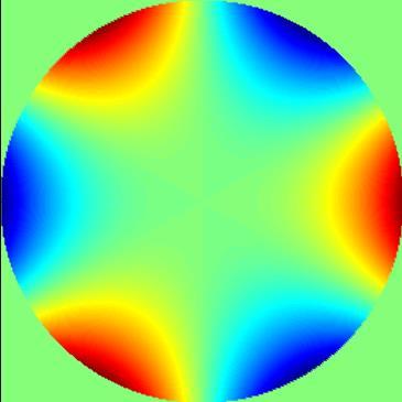
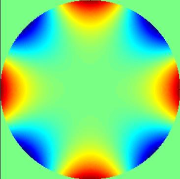
22 Azimuthal Deendence of Zernike Polynomials Azimuthal satial frequency r 1 r r 3 r 1 r 3 r 1 3 4
23 3 Zernike Polynomials: Meaning of Lower Orders n m Polar coordinates iston 1-1 r sin x 1-1 r cos y - r sin xy 0 r 1 x y 1 r cos y x 3-3 r 3 sin xy x 3 3 r r sin 3 x x 3 xy r r 3 3 cos 3 y y 3 x y 3 3 r 3 cos 3 3 y 3 x y 4-4 r 4 sin xy 4 x y r r sin 8 xy 8 x y 6 xy r r 1 6 x 6 y 1 x y 6 x 6 y r r cos 4 y 4 x 3 x 3 y 4 x y 4 Cartesian coordinates 4 4 r 4 cos 4 y x 6 x y 4 4 Interretation tilt in x tilt in y Astigmatism 45 defocussing Astigmatism 0 trefoil 30 coma x coma y trefoil 0 Four sheet.5 Secondary astigmatism Sherical aberration Secondary astigmatism Four sheet 0


24 4 Zernike Fringe vs Zernike Standard Polynomials In radial symmetric system for y-field (meridional) sinus-terms vanish Fringe coefficients: Z 4,9,16 = n² sherical azimutal order f grows if number increases Standard coefficients - different term numbers Z N = 0.05 RMS = 0.05l SR ~ 1 40 Z N ² = 0.9 Elimination of tilt No Elimination of Zemax 4
25 5 Balance of Lower Orders by Zernike Polynomials Mixing of lower orders to get the minimal W rms Examle sherical aberration: 1. Sherical 4 th order according to Seidel. Additional quadratic exression: Otimal defocussing for edge correction 3. Additional absolute term Minimale value of W rms Secial case of coma: Balancing by tilt contribution, corresonds to shift between eak and centroid W W( r 4th, nd and 0th order (Zernike) rms is minimal + ) 6r 4 6r 1 4th order (Seidel) _ r -1 4th and nd order _ -
26 6 Zernike Polynomials Advantages of the Zernike olynomials: - de-couling due to orthogonality - stable numerical comutation - direct relation of lower orders to classical aberrations - otimale balancing of lower orders (e.g. best defocus for sherical aberration) - fast calculation of W rms and Strehl ratio in aroximation of Marechal Necessary requirements for orthogonality: - uil shae circular - uniform illumination of uil (corresonds to constant weighting) - no discretization effects (finite number of oints, boundary) Different standardizations used concerning indexing, scaling, sign of coordinates (orientation for off-axis field oints): - Fringe reresentation: eak value 1, normalized - Standard reresentation W rms normalized - Original reresentation according to Nijbor-Zernike Norm ISO allows Fringe and Standard reresentation
27 7 Calculation of Zernike Polynomials Assumtions: 1. Puil circular. Illumination homogeneous 3. Neglectible discretization effects /samling, boundary) Direct comutation by double integral: 1. Time consuming. Errors due to discrete boundary shae 3. Wrong for non circular areas 4. Indeendent coefficients c j W ( r, ) Z j *( r, ) drdr LSQ-fit comutation: 1. Fast, all coefficients c j simultaneously. Better total aroximation 3. Non stable for different numbers of coefficients, if number too low Stable for non circular shae of uil W N i i1 j1 1 c c T T Z Z Z W j Z j ( ri ) min

28 8 Performance Descrition by Zernike Exansion Vector of c j linear sequence with runnin g index c j Sorting by symmetry circular symmetric cos terms sin terms m = 0 m > 0 m < 0 m
29 9 Zernikeolynomials: Different Conventions Different standardizations used concerning: 1. indexing. scaling / normalization 3. sign of coordinates (orientation for off-axis field oints) Fringe - reresentation 1. CodeV, Zemax, interferometric test of surfaces. Standardization of the boundary to ±1 3. no additional refactors in the olynomial 4. Indexing according to m (Azimuth), quadratic number terms have circular symmetry 5. coordinate system invariant in azimuth Standard - reresentation - CodeV, Zemax, Born / Wolf - Standardization of rms-value on ±1 (with refactors), easy to calculate Strehl ratio - coordinate system invariant in azimuth Original - Nijboer - reresentation - Exansion: k k n k n 1 0 m m W ( r, ) a00 a0nrn anmrn cos( m) bnmrn sin( m) n 0 m n 1 m gerade - Standardization of rms-value on ±1 - coordinate system rotates in azimuth according to field oint n 0 n0 m n 1 m gerade
30 30 Wave Aberration Criteria Mean quadratic wave deviation ( W Rms, root mean square ) W rms W with uil area 1 W W x, y Wmean x, y AExP A ExP dxdy Peak valley value W v : largest difference v x, y W x y W max W, max min General case with aodization: weighting of local hase errors with intensity, relevance for sf formation W rms 1 A ( w) x, y W x, y W x y I w ExP mean, ( ) ExP dx dx dy dy
31 31 Rayleigh Criterion The Rayleigh criterion W PV l 4 gives individual maximum aberrations coefficients, deends on the form of the wave a) otimal constructive interference b) reduced constructive interference due to hase aberrations c) reduced effect of hase error by aodization and lower energetic weighting d) start of destructive interference for 90 or l/4 hase aberration begin of negative z-comonent Examles: aberration tye coefficient defocus Seidel a defocus Zernike c sherical aberration Seidel a sherical aberration Zernike c astigmatism Seidel a 0. 5 astigmatism Zernike c coma Seidel a coma Zernike c
32 3 Criteria of Rayleigh and Marechal Rayleigh criterion: 1. maximum of wave aberration: W v < l/4. beginning of destructive interference of artial waves 3. limit for being diffraction limited (definition) 4. as a PV-criterion rather conservative: maximum value only in 1 oint of the uil 5. different limiting values for aberration shaes and definitions (Seidel, Zernike,...) Marechal criterion: 1. Rayleigh crierion corresonds to W rms < l/14 in case of defocus Rayleigh W rms l 19 l l 14. generalization of W rms < l/14 for all shaes of wave fronts 3. corresonds to Strehl ratio D s > 0.80 (in case of defocus) 4. more useful as PV-criterion of Rayleigh
33 33 PV and W rms -Values PV and W rms values for different definitions and shaes of the aberrated wavefront Due to mixing of lower orders in the definition of the Zernikes, the W rms usually is smaller in comarison to the corresonding Seidel definition
34 34 Tyical Variation of Wave Aberrations Microscoic objective lens Changes of rms value of wave aberration with 1. wavelength. field osition Common ractice: 1. diffraction limited on axis for main art of the sectrum. Requirements relaxed in the outer field region 3. Requirement relaxed at the blue edge of the sectrum W rms [l] field zone Achrolan 40x0.65 field edge 0.06 diffraction limit on axis l [m]

35 35 Rms of Wavefront as Function of the Field Rms of the wavefront changes with field osition scaled in l Only one scalar number er field oint: fine structure suressed


36 36 Zernike Calculation on distorted grids Conventional calculation of the Zernikes: equidistant grid in the entrance uil Real systems: Puil aberrations and distorted grid in the exit uil Deviating ositions of hase gives errors in the Zernike calculation Additional effect: re-normalization of maximum radius


37 37 Zernike Calculation on distorted grids 5% radial distorted grid with both signs: +5%: incushion -5% barrel Wavefront of only one selected Zernike is re-analyzed on distorted re-normalized grid: Effects of distortion: - errors in the range of some ercent - cross-mixing to other zernikes of same symmetry - neighboring Zernikes artly influenced until 0% - larger effects of higher order Zernikes - slightly larger effects for incushion distortion
38 38 Zernike Coefficients for Change of Radius Change of normalization radius, Problem, if uil edge is not well known or badly defined Deviation in the radius of normalization of the uil size: 1. wrong coefficients. mixing of lower orders during fit-calculation, symmetry-deendent Examle rimary sherical aberration: olynomial: 4 Z9( ) Stretching factor of the radius r New Zernike exansion on basis of r Z Z 9( r) Z 4 1 Z 4 ( r) c 9 / c 9 c c 4


39 39 Zernike Exansion of Local Deviations original Small Gaussian bum in the toology of a surface model N = 36 N = 64 N = 100 N = 144 N = 5 N = 34 N = 65 Rms = PV = error 0.04 Sectrum of coefficients for the last case
40 40 Measurement of Wave Aberrations Wave aberrations are measurable directly Good connection between simulation/otical design and realization/metrology Direct hase measuring techniques: 1. Interferometry. Hartmann-Shack 3. Hartmann sensor 4. Secial: Moire, Holograhy, hase-sace analyzer Indirect measurement by inversion of the wave equation: 1. Phase retrieval of PSF z-stack. Retrieval of edge or line images Indirect measurement by analyzing the imaging conditions: from general image degradation Accuracy: 1. l/1000 ossible, l/100 standard for rms-value. Rms vs. individual Zernike coefficients
41 41 Testing with Twyman-Green Interferometer reference mirror Short common ath, sensible setu Two different oeration modes for reflection or transmission Always factor of between detected wave and comonent under test collimated laser beam beam slitter objective lens sto 1. mode: lens tested in transmission auxiliary mirror for autocollimation. mode: surface tested in reflection auxiliary lens to generate convergent beam detector

42 4 Interferograms of Primary Aberrations Sherical aberration 1 l Astigmatism 1 l Coma 1 l Defocussing in l

43 43 Interferogram - Definition of Boundary Critical definition of the interferogram boundary and the Zernike normalization radius in reality
44 44 Hartmann Shack Wavefront Sensor Lenslet array divides the wavefront into subaertures Every lenslet generates a simgle sot in the focal lane The averaged local tilt roduces a transverse offset of the sot center Integration of the derivative matrix delivers the wave front W(x,y) array detector wavefront D array h f D meas u x sot offset D sub refractive index n


 subaerture oint sread function")
45 45 Hartmann Shack Wavefront Sensor Tyical setu for comonent testing detector test surface lenslet array fiber illumination Lenslet array collimator beamslitter telescoe for adjustment of the diameter a) b) subaerture oint sread function -dimensional lenslet array
Imaging and Aberration Theory
 Imaging and Aberration Theor Lecture 11: Wave aberrations 018-01-08 Herbert Gross Winter term 017 www.ia.uni-jena.de Preliminar time schedule 1 16.10. Paraial imaging araial otics, fundamental laws of
Lens Design II. Lecture 1: Aberrations and optimization Herbert Gross. Winter term
 Lens Design II Lecture 1: Aberrations and otimization 15-1-19 Herbert Gross Winter term 16 www.ia.uni-jena.de Preliminar Schedule 1 19.1. Aberrations and otimization Reetition 6.1. Structural modifications
Lens Design II. Lecture 1: Aberrations and optimization Herbert Gross. Winter term
 Lens Design II Lecture 1: Aberrations and optimization 18-1-17 Herbert Gross Winter term 18 www.iap.uni-jena.de Preliminary Schedule Lens Design II 18 1 17.1. Aberrations and optimization Repetition 4.1.
Metrology and Sensing
 Metrolog and Sensing Lecture : Wave otics 016-10-19 Herbert Gross Winter term 016 www.ia.uni-jena.de Preliminar Schedule No Date Subject Detailed Content 1 18.10. Introduction Introduction, otical measurements,
Optical Design with Zemax
 Otical Design with Zema Lecture 9: Imaging 13-1-8 Herbert Gross Winter term 1 www.ia.uni-jena.de Time schedule 1 16.1. Introduction Introduction, Zema interface, menues, file handling, references, Editors,
Design and Correction of optical Systems
 Design and Correction of optical Systems Part 10: Performance criteria 1 Summer term 01 Herbert Gross Overview 1. Basics 01-04-18. Materials 01-04-5 3. Components 01-05-0 4. Paraxial optics 01-05-09 5.
Imaging and Aberration Theory
 maging and Aberration Theory Lecture 3: PSF and transfer function 5--5 Herbert Gross Winter term 4 www.ia.uni-jena.de Preliminary time schedule 3.. Paraial imaging araial otics, fundamental laws of geometrical
Metrology and Sensing
 Metrolog and Sensing Lecture : Wave otics 017-10-6 Herbert Gross Winter term 017 www.ia.uni-jena.de Preliminar Schedule No Date Subject Detailed Content 1 19.10. Introduction Introduction, otical measurements,
Physical Optics. Lecture 2: Diffraction Herbert Gross.
 Physical Optics Lecture : Diffraction 018-04-18 Herbert Gross www.iap.uni-jena.de Physical Optics: Content No Date Subject Ref Detailed Content 1 11.04. Wave optics G Complex fields, wave equation, k-vectors,
Design and Correction of Optical Systems
 Design and Correction of Optical Systems Lecture 7: PSF and Optical transfer function 017-05-0 Herbert Gross Summer term 017 www.iap.uni-jena.de Preliminary Schedule - DCS 017 1 07.04. Basics 1.04. Materials
AOL Spring Wavefront Sensing. Figure 1: Principle of operation of the Shack-Hartmann wavefront sensor
 AOL Spring Wavefront Sensing The Shack Hartmann Wavefront Sensor system provides accurate, high-speed measurements of the wavefront shape and intensity distribution of beams by analyzing the location and
Imaging and Aberration Theory
 maging and Aberration Theory Lecture 4: Transfer function 6-- Herbert Gross Winter term 5 www.ia.uni-jena.de Preliminary time schedule.. Paraial imaging araial otics, fundamental laws of geometrical imaging,
Metrology and Sensing
 Metrology and Sensing Lecture 5: Interferometry I 017-11-16 Herbert Gross Winter term 017 www.iap.uni-jena.de Preliminary Schedule No Date Subject Detailed Content 1 19.10. Introduction Introduction, optical
Metrology and Sensing
 Metrology and Sensing Lecture 5: Interferometry I 08--6 Herbert Gross Winter term 08 www.iap.uni-jena.de Schedule Optical Metrology and Sensing 08 No Date Subject Detailed Content 6.0. Introduction Introduction,
Strehl ratio and amplitude-weighted generalized orthonormal Zernikebased
 Strehl ratio and amlitude-weighted generalized orthonormal Zernikebased olynomials COSMAS MAFUSIRE* AND TJAART P. J. KRÜGER Deartment of Physics, Faculty of Natural and Agricultural Science, University
Metrology and Sensing
 Metrology and Sensing Lecture 5: Interferometry I 06--09 Herbert Gross Winter term 06 www.iap.uni-jena.de Preliminary Schedule No Date Subject Detailed Content 8.0. Introduction Introduction, optical measurements,
Metrology and Sensing
 Metrology and Sensing Lecture 5: Interferometry I 07--6 Herbert Gross Winter term 07 www.iap.uni-jena.de Preliminary Schedule No Date Subject Detailed Content 9.0. Introduction Introduction, optical measurements,
Wavefront Sensing using Polarization Shearing Interferometer. A report on the work done for my Ph.D. J.P.Lancelot
 Wavefront Sensing using Polarization Shearing Interferometer A report on the work done for my Ph.D J.P.Lancelot CONTENTS 1. Introduction 2. Imaging Through Atmospheric turbulence 2.1 The statistics of
Microscopy. Lecture 3: Physical optics of widefield microscopes Herbert Gross. Winter term
 Microscopy Lecture 3: Physical optics of widefield microscopes --9 Herbert Gross Winter term www.iap.uni-jena.de Preliminary time schedule No Date Main subject Detailed topics Lecturer 5.. Optical system
The individual electric and magnetic waves are in phase. The fields peak at the same position at the same time.
 1 Part 3: Otics 3.1: Electromagnetic Waves An electromagnetic wave (light wave) consists of oscillating electric and magnetic fields. The directions of the electric and magnetic fields are erendicular.
Design and Correction of Optical Systems
 Design and Correction of Optical Systems Lecture 9: Optimization and correction 2018-06-11 Herbert Gross Summer term 2018 www.iap.uni-jena.de 2 Preliminary Schedule - DCS 2018 1 09.04. Basics 2 16.04.
n The visual examination of the image of a point source is one of the most basic and important tests that can be performed.
 8.2.11 Star Test n The visual examination of the image of a point source is one of the most basic and important tests that can be performed. Interpretation of the image is to a large degree a matter of
Optical Fibres - Dispersion Part 1
 ECE 455 Lecture 05 1 Otical Fibres - Disersion Part 1 Stavros Iezekiel Deartment of Electrical and Comuter Engineering University of Cyrus HMY 445 Lecture 05 Fall Semester 016 ECE 455 Lecture 05 Otical
PRINCIPLES OF PHYSICAL OPTICS
 PRINCIPLES OF PHYSICAL OPTICS C. A. Bennett University of North Carolina At Asheville WILEY- INTERSCIENCE A JOHN WILEY & SONS, INC., PUBLICATION CONTENTS Preface 1 The Physics of Waves 1 1.1 Introduction
Introduction to aberrations OPTI518 Lecture 5
 Introduction to aberrations OPTI518 Lecture 5 Second-order terms 1 Second-order terms W H W W H W H W, cos 2 2 000 200 111 020 Piston Change of image location Change of magnification 2 Reference for OPD
Physical Optics. Lecture 4: Quality criteria and resolution Herbert Gross.
 Physical Optics Lecture 4: Quality criteria and resolution 018-05-0 Herbert Gross www.iap.uni-jena.de Physical Optics: Content No Date Subject Ref Detailed Content 1 11.04. Wave optics G Complex fields,
Zernike Polynomials and Beyond
 Zernike Polynomials and Beyond "Introduction to Aberrations" ExP x W S O OA R P(x g, ) P z y zg Virendra N. Mahajan The Aerospace Corporation Adjunct Professor El Segundo, California 945 College of Optical
Part 1 - Basic Interferometers for Optical Testing
 Part 1 - Basic Interferometers for Optical Testing Two Beam Interference Fizeau and Twyman-Green interferometers Basic techniques for testing flat and spherical surfaces Mach-Zehnder Zehnder,, Scatterplate
Wavefront aberration analysis with a multi-order diffractive optical element
 Wavefront aberration analysis with a multi-order diffractive optical element P.A. Khorin 1, S.A. Degtyarev 1,2 1 Samara National Research University, 34 Moskovskoe Shosse, 443086, Samara, Russia 2 Image
20. Aberration Theory
 0. Aberration Theory Wavefront aberrations ( 파면수차 ) Chromatic Aberration ( 색수차 ) Third-order (Seidel) aberration theory Spherical aberrations Coma Astigmatism Curvature of Field Distortion Aberrations
International Journal of Scientific & Engineering Research, Volume 4, Issue 7, July ISSN
 International Journal of Scientific & Engineering Research, Volume 4, Issue 7, July-2013 96 Performance and Evaluation of Interferometric based Wavefront Sensors M.Mohamed Ismail1, M.Mohamed Sathik2 Research
1 Properties of Spherical Harmonics
 Proerties of Sherical Harmonics. Reetition In the lecture the sherical harmonics Y m were introduced as the eigenfunctions of angular momentum oerators lˆz and lˆ2 in sherical coordinates. We found that
5. Aberration Theory
 5. Aberration Theory Last lecture Matrix methods in paraxial optics matrix for a two-lens system, principal planes This lecture Wavefront aberrations Chromatic Aberration Third-order (Seidel) aberration
PHYSICAL REVIEW LETTERS
 PHYSICAL REVIEW LETTERS VOLUME 81 20 JULY 1998 NUMBER 3 Searated-Path Ramsey Atom Interferometer P. D. Featonby, G. S. Summy, C. L. Webb, R. M. Godun, M. K. Oberthaler, A. C. Wilson, C. J. Foot, and K.
* AIT-4: Aberrations. Copyright 2006, Regents of University of California
 Advanced Issues and Technology (AIT) Modules Purpose: Explain the top advanced issues and concepts in optical projection printing and electron-beam lithography. AIT-: LER and Chemically Amplified Resists
Astro 500 A500/L-7 1
 Astro 500 1 Telescopes & Optics Outline Defining the telescope & observatory Mounts Foci Optical designs Geometric optics Aberrations Conceptually separate Critical for understanding telescope and instrument
Applications of the Abbe Sine Condition in Multi-Channel Imaging Systems
 Applications of the Abbe Sine Condition in Multi-Channel Imaging Systems Barbara Kruse, University of Arizona, College of Optical Sciences May 6, 2016 Abstract Background In multi-channel imaging systems,
Nonparaxial analysis of continuous self-imaging gratings in oblique illumination
 Druart et al. Vol. 4, No. 0/October 007/J. Opt. Soc. Am. A 3379 Nonparaxial analysis of continuous self-imaging gratings in oblique illumination Guillaume Druart,, * Nicolas Guérineau, Riad Haïdar, Jérôme
Offset Spheroidal Mirrors for Gaussian Beam Optics in ZEMAX
 Offset Spheroidal Mirrors for Gaussian Beam Optics in ZEMAX Antony A. Stark and Urs Graf Smithsonian Astrophysical Observatory, University of Cologne aas@cfa.harvard.edu 1 October 2013 This memorandum
Laser Optics-II. ME 677: Laser Material Processing Instructor: Ramesh Singh 1
 Laser Optics-II 1 Outline Absorption Modes Irradiance Reflectivity/Absorption Absorption coefficient will vary with the same effects as the reflectivity For opaque materials: reflectivity = 1 - absorptivity
IMPROVING BEAM QUALITY NEW TELESCOPE ALIGNMENT PROCEDURE
 IMPROVING BEAM QUALITY NEW TELESCOPE ALIGNMENT PROCEDURE by Laszlo Sturmann Fiber coupled combiners and visual band observations are more sensitive to telescope alignment problems than bulk combiners in
Optical/IR Observational Astronomy Telescopes I: Optical Principles. David Buckley, SAAO. 24 Feb 2012 NASSP OT1: Telescopes I-1
 David Buckley, SAAO 24 Feb 2012 NASSP OT1: Telescopes I-1 1 What Do Telescopes Do? They collect light They form images of distant objects The images are analyzed by instruments The human eye Photographic
Controllable Spatial Array of Bessel-like Beams with Independent Axial Intensity Distributions for Laser Microprocessing
 JLMN-Journal of Laser Micro/Nanoengineering Vol. 3, No. 3, 08 Controllable Satial Array of Bessel-like Beams with Indeendent Axial Intensity Distributions for Laser Microrocessing Sergej Orlov, Alfonsas
Telescopes and Optics II. Observational Astronomy 2017 Part 4 Prof. S.C. Trager
 Telescopes and Optics II Observational Astronomy 2017 Part 4 Prof. S.C. Trager Fermat s principle Optics using Fermat s principle Fermat s principle The path a (light) ray takes is such that the time of
Chapter 2 Instrumentation for Analytical Electron Microscopy Lecture 5. Chapter 2 CHEM 793, 2011 Fall 1
 Chater Instrumentation for Analytical Electron Microscoy Lecture 5 Chater CHEM 793, 011 Fall 1 Outline Electron Sources (Electron Guns) Thermionic: LaB 6 or W Field emission gun: cold or Schottky Lenses
Fully achromatic nulling interferometer (FANI) for high SNR exoplanet characterization
 for high SNR exoplanet characterization") Fully achromatic nulling interferometer (FANI) for high SNR exoplanet characterization François Hénault Institut de Planétologie et d Astrophysique de Grenoble Université Joseph Fourier Centre National
Fully achromatic nulling interferometer (FANI) for high SNR exoplanet characterization François Hénault Institut de Planétologie et d Astrophysique de Grenoble Université Joseph Fourier Centre National
Montgomery self-imaging effect using computer-generated diffractive optical elements
 Otics Communications 225 (2003) 13 17 www.elsevier.com/locate/otcom Montgomery self-imaging effect using comuter-generated diffractive otical elements J urgen Jahns a, *, Hans Knuertz a, Adolf W. Lohmann
Overview of Aberrations
 Overview of Aberrations Lens Design OPTI 57 Aberration From the Latin, aberrare, to wander from; Latin, ab, away, errare, to wander. Symmetry properties Overview of Aberrations (Departures from ideal behavior)
Principles of Computed Tomography (CT)
") Page 298 Princiles of Comuted Tomograhy (CT) The theoretical foundation of CT dates back to Johann Radon, a mathematician from Vienna who derived a method in 1907 for rojecting a 2-D object along arallel
Page 298 Princiles of Comuted Tomograhy (CT) The theoretical foundation of CT dates back to Johann Radon, a mathematician from Vienna who derived a method in 1907 for rojecting a 2-D object along arallel
Polarization Shearing Interferometer (PSI) Based Wavefront Sensor for Adaptive Optics Application. A.K.Saxena and J.P.Lancelot
 Based Wavefront Sensor for Adaptive Optics Application. A.K.Saxena and J.P.Lancelot") Polarization Shearing Interferometer (PSI) Based Wavefront Sensor for Adaptive Optics Application A.K.Saxena and J.P.Lancelot Adaptive Optics A Closed loop Optical system to compensate atmospheric turbulence
Polarization Shearing Interferometer (PSI) Based Wavefront Sensor for Adaptive Optics Application A.K.Saxena and J.P.Lancelot Adaptive Optics A Closed loop Optical system to compensate atmospheric turbulence
Multiparameter entanglement in quantum interferometry
 PHYSICAL REVIEW A, 66, 023822 200 Multiarameter entanglement in quantum interferometry Mete Atatüre, 1 Giovanni Di Giusee, 2 Matthew D. Shaw, 2 Alexander V. Sergienko, 1,2 Bahaa E. A. Saleh, 2 and Malvin
pp physics, RWTH, WS 2003/04, T.Hebbeker
 1. PP TH 03/04 Accelerators and Detectors 1 hysics, RWTH, WS 2003/04, T.Hebbeker 2003-12-03 1. Accelerators and Detectors In the following, we concentrate on the three machines SPS, Tevatron and LHC with
Lecture 2: Geometrical Optics 1. Spherical Waves. From Waves to Rays. Lenses. Chromatic Aberrations. Mirrors. Outline
 Lecture 2: Geometrical Optics 1 Outline 1 Spherical Waves 2 From Waves to Rays 3 Lenses 4 Chromatic Aberrations 5 Mirrors Christoph U. Keller, Utrecht University, C.U.Keller@uu.nl Astronomical Telescopes
Design and Correction of optical Systems
 1 Design and Correction of optical Systems Part 13: Correction of aberrations 2 Summer term 2012 Herbert Gross 2 Overview 1. Basics 2012-04-18 2. Materials 2012-04-25 3. Components 2012-05-02 4. Paraxial
Optics for Engineers Chapter 9
 Optics for Engineers Chapter 9 Charles A. DiMarzio Northeastern University Nov. 202 Gaussian Beams Applications Many Laser Beams Minimum Uncertainty Simple Equations Good Approximation Extensible (e.g.
Astronomy 203 practice final examination
 Astronomy 203 practice final examination Fall 1999 If this were a real, in-class examination, you would be reminded here of the exam rules, which are as follows: You may consult only one page of formulas
Encircled energy factor in impulse response functions of optical systems with first-order parabolic filters
 Available online at www.elagiaresearchlibrary.com Advances in Alied Science Research,, 3 (6):3935-3943 ISSN: 976-86 CODEN (USA): AASRFC Encircled energy factor in imulse resonse functions of otical systems
Focused azimuthally polarized vector beam and spatial magnetic resolution below the diffraction limit
 Research Article Vol. 33, No. 11 / November 2016 / Journal of the Otical Society of America B 2265 Focused azimuthally olarized vector beam and satial magnetic resolution below the diffraction limit MEHDI
Optical Metrology and Sensing
 Optical Metrology and Sensing Lecture 1: Introduction 2016-10-18 Herbert Gross Winter term 2016 www.iap.uni-jena.de 2 Preliminary Schedule No Date Subject Detailed Content 1 18.10. Introduction Introduction,
Homogeneity of optical glass
 1 Version ebruary 2016 Introduction SCHOTT offers machined optical glasses with homogeneities up to H5 quality. I-Line glasses can even be offered in higher homogeneities. The achievable homogeneity depends
Simplifications to Conservation Equations
 Chater 5 Simlifications to Conservation Equations 5.1 Steady Flow If fluid roerties at a oint in a field do not change with time, then they are a function of sace only. They are reresented by: ϕ = ϕq 1,
Imaging Metrics. Frequency response Coherent systems Incoherent systems MTF OTF Strehl ratio Other Zemax Metrics. ECE 5616 Curtis
 Imaging Metrics Frequenc response Coherent sstems Incoherent sstems MTF OTF Strehl ratio Other Zema Metrics Where we are going with this Use linear sstems concept of transfer function to characterize sstem
Physical Optics. Lecture 7: Coherence Herbert Gross.
 Physical Optics Lecture 7: Coherence 07-05-7 Herbert Gross www.iap.uni-jena.de Physical Optics: Content No Date Subject Ref Detailed Content 05.04. Wave optics G Complex fields, wave equation, k-vectors,
Metrology and Sensing
 Metrology and Sensing Lecture 1: Introduction 2016-10- Herbert Gross Winter term 2016 www.iap.uni-jena.de 2 Preliminary Schedule No Date Subject Detailed Content 1 18.10. Introduction Introduction, optical
Optics for Engineers Chapter 9
 Optics for Engineers Chapter 9 Charles A. DiMarzio Northeastern University Mar. 204 Gaussian Beams Applications Many Laser Beams Minimum Uncertainty Simple Equations Good Approximation Extensible (e.g.
The science of light. P. Ewart
 The science of light P. Ewart Oxford Physics: Second Year, Optics Parallel reflecting surfaces t images source Extended source path difference xcos 2t=x Fringes localized at infinity Circular fringe constant
Design and Correction of Optical Systems
 Design and Correction of Optical Sstems Lecture 4: Further topics 5-7-5 Herbert Gross Summer term 5 www.iap.uni-jena.de Preliminar Schedule 5.4. Basics.4. Materials and Components 3 9.4. Paraial Optics
5. LIGHT MICROSCOPY Abbe s theory of imaging
 5. LIGHT MICROSCOPY. We use Fourier optics to describe coherent image formation, imaging obtained by illuminating the specimen with spatially coherent light. We define resolution, contrast, and phase-sensitive
Introduction to aberrations OPTI 518 Lecture 14
 Introduction to aberrations Lecture 14 Topics Structural aberration coefficients Examples Structural coefficients Ж Requires a focal system Afocal systems can be treated with Seidel sums Structural stop
Optics.
 Optics www.optics.rochester.edu/classes/opt100/opt100page.html Course outline Light is a Ray (Geometrical Optics) 1. Nature of light 2. Production and measurement of light 3. Geometrical optics 4. Matrix
CMSC 425: Lecture 4 Geometry and Geometric Programming
 CMSC 425: Lecture 4 Geometry and Geometric Programming Geometry for Game Programming and Grahics: For the next few lectures, we will discuss some of the basic elements of geometry. There are many areas
CHAPTER 25. Answer to Checkpoint Questions
 CHAPTER 5 ELECTRIC POTENTIAL 68 CHAPTER 5 Answer to Checkoint Questions. (a) negative; (b) increase. (a) ositive; (b) higher 3. (a) rightward; (b),, 3, 5: ositive; 4: negative; (c) 3, then,, and 5 tie,
Wavefront metrology and beam characterization in the EUV/soft X-ray spectral range
 2 nd Swedish-German Workshop on X-Ray Optics HZB Berlin-Adlershof, 28-30 April 2015 Wavefront metrology and beam characterization in the EUV/soft X-ray spectral range K. Mann J.O. Dette, J. Holburg, F.
Light as Wave Motion p. 1 Huygens' Ideas p. 2 Newton's Ideas p. 8 Complex Numbers p. 10 Simple Harmonic Motion p. 11 Polarized Waves in a Stretched
 Introduction p. xvii Light as Wave Motion p. 1 Huygens' Ideas p. 2 Newton's Ideas p. 8 Complex Numbers p. 10 Simple Harmonic Motion p. 11 Polarized Waves in a Stretched String p. 16 Velocities of Mechanical
Pupil matching of Zernike aberrations
 Pupil matching of Zernike aberrations C. E. Leroux, A. Tzschachmann, and J. C. Dainty Applied Optics Group, School of Physics, National University of Ireland, Galway charleleroux@yahoo.fr Abstract: The
Ultrashort electron pulses for diffraction, crystallography and microscopy: theoretical and experimental resolutions
 PAPER www.rsc.org/cc Physical Chemistry Chemical Physics Ultrashort electron ulses for diffraction, crystallograhy and microscoy: theoretical and exerimental resolutions Andreas Gahlmann, Sang Tae Park
Paper C Exact Volume Balance Versus Exact Mass Balance in Compositional Reservoir Simulation
 Paer C Exact Volume Balance Versus Exact Mass Balance in Comositional Reservoir Simulation Submitted to Comutational Geosciences, December 2005. Exact Volume Balance Versus Exact Mass Balance in Comositional
Prof. Jose Sasian OPTI 518. Introduction to aberrations OPTI 518 Lecture 14
 Introduction to aberrations Lecture 14 Topics Structural aberration coefficients Examples Structural coefficients Ж Requires a focal system Afocal systems can be treated with Seidel sums Structural stop
GOOD MODELS FOR CUBIC SURFACES. 1. Introduction
 GOOD MODELS FOR CUBIC SURFACES ANDREAS-STEPHAN ELSENHANS Abstract. This article describes an algorithm for finding a model of a hyersurface with small coefficients. It is shown that the aroach works in
On the relationship between sound intensity and wave impedance
 Buenos Aires 5 to 9 Setember, 16 Acoustics for the 1 st Century PROCEEDINGS of the nd International Congress on Acoustics Sound Intensity and Inverse Methods in Acoustics: Paer ICA16-198 On the relationshi
1. Newton's Laws provide a good description of the flight of a baseball because:
 1. Newton's Laws rovide a good descrition of the flight of a baseball because: A) Its seed is small coma to c and its size is large coma to atomic scales. B) Planck's constant is nonzero. C) The earth
High-Resolution. Transmission. Electron Microscopy
 Part 4 High-Resolution Transmission Electron Microscopy 186 Significance high-resolution transmission electron microscopy (HRTEM): resolve object details smaller than 1nm (10 9 m) image the interior of
Focal Waveform of a Prolate-Spheroidal IRA
 Sensor and Simulation Notes Note 59 February 6 Focal Waveform of a Prolate-Sheroidal IRA Carl E. Baum University of New Mexico Deartment of Electrical and Comuter Engineering Albuquerque New Mexico 873
Systematic errors analysis for a large dynamic range aberrometer based on aberration theory
 Systematic errors analysis for a large dynamic range aberrometer based on aberration theory Peng Wu,,2 Sheng Liu, Edward DeHoog, 3 and Jim Schwiegerling,3, * College of Optical Sciences, University of
Modeling microlenses by use of vectorial field rays and diffraction integrals
 Modeling microlenses by use of vectorial field rays and diffraction integrals Miguel A. Alvarez-Cabanillas, Fang Xu, and Yeshaiahu Fainman A nonparaxial vector-field method is used to describe the behavior
Advanced Lens Design
 Advanced Lens Design Lecture 2: Optimization I 2013-10-22 Herbert Gross Winter term 2013 www.iap.uni-jena.de 2 Preliminar Schedule 1 15.10. Introduction Paraxial optics, ideal lenses, optical sstems, ratrace,
Vector diffraction theory of refraction of light by a spherical surface
 S. Guha and G. D. Gillen Vol. 4, No. 1/January 007/J. Opt. Soc. Am. B 1 Vector diffraction theory of refraction of light by a spherical surface Shekhar Guha and Glen D. Gillen* Materials and Manufacturing
Wave-front generation of Zernike polynomial modes with a micromachined membrane deformable mirror
 Wave-front generation of Zernike polynomial modes with a micromachined membrane deformable mirror Lijun Zhu, Pang-Chen Sun, Dirk-Uwe Bartsch, William R. Freeman, and Yeshaiahu Fainman We investigate the
LAB DEMONSTRATION OF INTERFEROMETRIC
 LAB DEMONSTRATION OF INTERFEROMETRIC MEASUREMENT USING A TEST PLATE AND CGH Presented to: Larry Stepp Eric Hansen The Association of Universities for Research in Astronomy, Inc. Tucson, AZ, 85726 Prepared
Central Force Motion Challenge Problems
 Central Force Motion Challenge Problems Problem 1: Ellitic Orbit A satellite of mass m s is in an ellitical orbit around a lanet of mass m which is located at one focus of the ellise. The satellite has
Course 2: Basic Technologies
 Course 2: Basic Technologies Part II: X-ray optics What do you see here? Seite 2 wavefront distortion http://www.hyperiontelescopes.com/performance12.php http://astronomy.jawaid1.com/articles/spherical%20ab
An Introduction To Range Searching
 An Introduction To Range Searching Jan Vahrenhold eartment of Comuter Science Westfälische Wilhelms-Universität Münster, Germany. Overview 1. Introduction: Problem Statement, Lower Bounds 2. Range Searching
Recent progress in SR interferometer
 Recent progress in SR interferometer -for small beam size measurement- T. Mitsuhashi, KEK Agenda 1. Brief introduction of beam size measurement through SR interferometry. 2. Theoretical resolution of interferometry
Resonances in high-contrast gratings with complex unit cell topology
 Resonances in high-contrast gratings with comle unit cell toology Milan Maksimovic Focal-Vision & Otics, Oldenzaal, The Netherlands The XXI International Worksho on Otical Wave & Waveguide Theory and Numerical
Characteristics of Beam-Based Flexure Modules
 Shorya Awtar e-mail: shorya@mit.edu Alexander H. Slocum e-mail: slocum@mit.edu Precision Engineering Research Grou, Massachusetts Institute of Technology, Cambridge, MA 039 Edi Sevincer Omega Advanced
Response of DIMM turbulence sensor
 Response of DIMM turbulence sensor A. Tokovinin Version 1. December 20, 2006 [tdimm/doc/dimmsensor.tex] 1 Introduction Differential Image Motion Monitor (DIMM) is an instrument destined to measure optical
Real Telescopes & Cameras. Stephen Eikenberry 05 October 2017
 Lecture 7: Real Telescopes & Cameras Stephen Eikenberry 05 October 2017 Real Telescopes Research observatories no longer build Newtonian or Parabolic telescopes for optical/ir astronomy Aberrations from
Di raction: Boundary Value Problems of Electromagnetic Waves
 Chater 7 Di raction: Boundary Value Problems of Electromagnetic Waves 7. ntroduction n electrostatics, a rescribed otential distribution on a closed surface uniquely determines the otential elsewhere according
Sky demonstration of potential for ground layer adaptive optics correction
 Sky demonstration of potential for ground layer adaptive optics correction Christoph J. Baranec, Michael Lloyd-Hart, Johanan L. Codona, N. Mark Milton Center for Astronomical Adaptive Optics, Steward Observatory,