INSTRUMENTATION AND CONTROL SYSTEMS LAB
|
|
|
- Egbert Jackson
- 5 years ago
- Views:
Transcription
1 INSTRUMENTATION AND CONTROL SYSTEMS LAB
2 INDEX S.No. Name of the Experiment Page No. 1 Linear Variable Differential Transformer (L.V.D.T) 2 Speed Measurement Module 3 Capacitive Pickup 4 Thermister Module 5 Strain Gauge 6 Resistance Temperature Detector (R.T.D) Module 7 Light Dependent Resistance
3 CALIBRATION OF LVDT FOR DISPLACEMENT MEASUREMENT
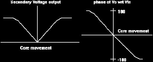
4 MEASUREMENT OF DISPLACEMENT USING L.V.D.T AIM: To measure the linear displacement using Linear Variable Differential Transformer (L.V.D.T.) APPARATUS: Digital instrumentation tutor, L.V.D.T. THEORY: LVDT converts linear motion into an electrical signal. It is used for measuring displacement. The LVDT consists of a primary winding and two secondary windings, which are wound on cylindrical former. The two secondary windings S 1 & S 2 have equal number of turns. The secondary windings are placed identically on either side of the primary winding. The primary winding is connected to an a.c. source. A movable core is placed inside the cylindrical former. PRINCIPLE: As the primary winding is connected to the a.c. source. It is excited and hence a magnetic field is produced. Due to this magnetic field, a voltage is induced in the secondary windings. The differential output is E 0 = E s1 -E s2 When the core is in the normal (null) position, the magnetic field linking with both the secondary windings S 1 & S 2 are equal. Hence the e.m.f. induced in them are also equal.
5 There fore null position E 0 = 0 (E s1 = E s2 ). When the core is moved to the right of the null position, more magnetic field links with the winding S 2 and less with winding S 1. Therefore E s2 > E s1. The output voltage E 0 = E s2 E s1 and is in the phase E s2. When the core is moved to the left of the null position more magnetic field links with the winding S 1 and less with the winding S 2. Therefore E s1 > E s2. The output voltage of the L.V.D.T. gives a measure of the physical position of the core and it s displacement. PROCEDURE: 1. Connect the terminals marked PRIMARY on the front panel of the instrument to the terminals marked PRIMARY on the transducer itself, with the help of flexible wires provided along with. Observe the colour code for the wires provided and the colour of the binding posts. 2. Similarly connect the terminals marked secondary. 3. Keep pot marked MAX in most anticlock- wise position. 4. The magnetic core may be displaced and the pointer may be brought to zero position. If the DPM is not indicating zero, use potentiometer marked MIN to get a zero on DPM at zero mechanical position. If the core is displaced in both directions, the meter must show indications with appropriate polarity. Now displace the core to 19 mm positions in one of the directions. Adjust the MAX pot to get an indication of on the DPM under this condition. Now the set up is ready for experimentation. You may again check for zero position also. 5. Now the core can be moved by a known amount in the range ± 19 mm and the DPM readings are taken in the table given below. It may noted that by inter changing the secondary terminals ro the primary, the polarity of the meter indication can be reversed for a given deirection of input displacement. 6. Plot the graph of input displacement and the output indication on the x and y axis respectively.
6 OBSERVATIONS: Sl.No. Input Displacement (mm) Output Indication (mm) Difference (mm) Percentage Error PRECAUTIONS: 1. Move the core with a gentle fashion. 2. While connecting lead wire from panel to transducer make proper connectionsfollowing colour code. Avoid 3. Avoid starting of the excitations source terminals. 4. Donot try to effect the core movement beyond 20 mm as per the given range. OBSERVATIONS : Study the linearity of input and output displacements. Note the effects of interchanging the secondary connections on the meter output polarity Note that when the core is mechanically at zero position, a small electrical output is obtained due to imperfections of the transducer.

7 GRAPH: Input Displacement Vs DPM Reading RESULT:
8 STUDY AND CALIBRATION OF PHOTO AND MAGNETIC PICKUP FOR SPEED MEASUREMENT
9 MEASUREMENT OF SPEED AIM: To measure the speed of a motor by Photo Pickup and Magnetic Pickup methods. APPARATUS:. Tachometer, DPM THEORY: There are two methods for the measurement of speed of a motor shaft with the help of non-contact pickups. i. Magnetic pickup: In this type of device, a small toothed wheel is to be attached to the shaft whose speed is to be determined. A parmanent magnet with a coil wound around around it is placed near the rotating toothed wheel. As the wheel rotates, the magnetic flux linking the magnet and coil changes. As a result voltage is induced in the coil. The frequency of the pulses depends upon the number of teeth on the wheel. Speed of the shaft = Pulses per Second Number of teeth on the wheel ii. Photo electric pickup: This is another method of speed measurement based on photo electric effect. An opaque disc with evenly spaced holes on its periphery is to be attatched to the shaft whose speed to be
10 measured. A light source is placed on one side and a light sensitive transducer on the other side of the disc. Both are in alignment with the holes in disc. As the disc rotates the intermittent light falling on the photocell produces voltage pulses whose frequency is a measure of the speed of the shaft. Remaining is same as inductive pickup. PROCEDURE: 1. Connect the calibration source to the input socket by the cable provided and connect the O/P terminals to the DPM observing polarity. 2. Adjust the pot marked max to get 1500 as the meter (DPM). Now the set up is calibrated from 1500rpm, Neglect decimal point. 3. Connect the photo electric and magnetic pickup in proper fashion. 4. Connect the motor terminal cable to the O/P terminals of D.C. supply ensure that dimmer knob is in zero position. Switch on the power supply and control slowly so on changing the speed of motor. 5. Motor speed will be indicated by the DPM for each pickup 6. Compare the DPM reading with digital tachometer reading.
11 OBSERVATIONS: S.No Tachomet er (RPM) Photo pickup (RPM) Percentage error Tachometer (RPM) Magnetic pickup (RPM) Percentage error PRECAUTIONS: 1. Always start the motor with zero speed and operate the knob slowly. 2. As soon as the experment is over disconnect the photo-electric and and magnetic pick-ups. RESULT:
12 ANGULAR DISPLACEMENT MEASUREMENT CAPACITIVE PICK UP
13 ANGULAR DISPLACEMENT MEASUREMENT CAPACITIVE PICK UP AIM: Study the measurement of angular displacement using capacitive pick up APPARATUS: Capacitive transducer, D.P.M THEORY: Capacitance is well known to be function of effective area of the conductors, separation between them, and the dielectric strength of the material in separation. Any one of these three can be the varying factor causing a change in capacitance. The capacitive transducer along with this equipment is based on the principle of variation of effective area of the conductors, other parameters i.e. separation, distance and dielectric strength being kept constant. A two ganged condenser normally used in transistor radio receivers, is used to demonstrate the measurement of angular displacement measurement.
14 OPERATION 1. Connect the capacitive pick up cable to the input socket on the main unit. 2. Keep the input angular displacement to zero position. 3. Check for zero indication on the DPM. Otherwise by operating potentiometer marked MIN (P2).obtain zero indication for zero angular position of the shaft. 4. Now turn the shaft of the capacitive pick up to fully clock wise position in a gentle manner corresponding to 180 degrees by operating knob marked MAX (P1). If required again check for zero indication. 5. Note down the reading corresponding to input angular displacement and indicated angular displacement on the DPM.
15 OBSERVATIONS S.No Input Angular Displacement DPM Indication Percentage error OBSEVATIONS : There is lot of non linearity of the indicated versus true reading. The reason is the non-linearity of the input angular displacement and the capacitance of the gang condenser. This method of angular displacement is free from mechanical friction (neglecting the friction in the ball bearings of the shaft).this a distinct advantage over potentiometric method. PRECAUTIONS : 1. Operate the sensor knob carefully 2. Do not stretch the wire coming from the capacitive sensor. RESULT:
16 TEMPERATURE MEASUREMENT USING THERMISTER
17 MEASUREMENT OF TEMPERATURE USING THERMISTOR AIM: To measure temperature using thermistor. APPARATUS: Thermistor, heater & container, DPM. THEORY: Thermistors are made of semi conductors of ceramic materials that are exceptionally sensitive to temperature. The main parts of the thermistor are: i. A metal tube which houses a thermistor sensing element. ii. An insulation sperates the thermistor sensing element from metal tube. Lead wire are drawn out from the thermistor sensing element. iii. The metal tube, sensing element and leads together became a thermistor used to measure temperature. iv. The material is made by sintering oxides of metals such as manganese, nickel, cobalt, copper, iron etc. Physical forms may be beads, discs, washer, rod type. The resistance of the thermistor decreases with increase in temperature. Hence they are called Negative temperature coefficient (N.T.C). They are highly sensitive to small temperature changes. v. A typical thermistor will exhibit a decrease in resistivity by a factor of 50 : 1 over temperature range of 0 to 100 O C.The highest temperature up to which thermistors can be used is limited to about 200 degree centigrade.
18 PROCEDURE: 1) Connect a shorting link across the input terminals and use pot P 1 on the front panel to get Zero indication on the DPM. The switch SW 2 may be kept in lower position corresponding to 2 kilo ohm range. Connect the thermistor across the input terminals remember the polarity is not important. 2) Connect the terminals marked O/P to DPM input terminal. 3) Now the thermistor may be immersed in boiling water and the resistance of the transducer should be noted down.
19 4) Switch off the heater supply and note the value of resistance for temperature reading from mercury in glass thermometer and note down the relationship between thermistor resistance and temperature up to ambient temperature. Enter the results in the following table. PRECAUTIONS: 1. Handle the eqipment carefully. 2. The thermistor wire should not touch the heater. OBSERVATIONS: S.No Thermometer temp reading ( o c) Resistance of thermistor in Ω Percentage error 1. The input/out put relationship (Temperature /Resistance) is highly non linear for this transducer. 2. In comparison with RTD, change in resistance for given change in temperature is very large I,e, it has higher sensitivity. Hence small i.e. differential change in temperature can be accurately monitored with the help of thermistors. GRAPH: Resistance versus temperature relationship can be plotted on a graph. RESULT:
20 STRAIN MEASUREMENT USING STRAIN GUAGE
21 STRAIN MEASUREMENT USING STRAIN GUAGE AIM: Measurement of strain using strain gauge. APPARATUS: Digital panel meter, cantilever beam, weights. THEORY: Strain gauges are devices used to measure the dimensional change of components under test. These are used in many applications like force measuring devices, measurement of vibration, measurement of pressure etc., In this experiment bonded strain gauges are used. These gauges are directly bonded (that is pasted) on the surface of the structure under study. In this fine wire strain gauges are used. A fine resistance wire of diameter of 0.025mm, which is bent again and again as shown in figure. This is due to increase the length of the wire so that it permits a uniform distribution of stress. This resistance wire is placed between the two carrier bases (paper, bakelite or Teflon), which are cemented to each other. The carrier base protects the gauge from damages. Loads are provided for electrically connecting the strain gauge to a measuring instrument (wheat stone bridge).
22 PROCEDURE: 1. Ensure that the instrument is switched off. 2. Connect the flexible wires provided with the strain gauge cantilever beam between the terminals 1-1,2-2,3-3 & Keep switch S1 to right position marked. 4. Turn ON the main supply by gently moving the balance. Put p1 and p2 obtain initial balance on the meter and wait for 5 minutes to allow the strain gauge temperature to stabilize. 5. Now apply a gentle pressure with hand on the end of the cantilever beam, the Digital Panel Meter (DPM) should indicate some change in reading. This indicates the strain gauge setup is ready for experiment dial. 6. Now keep p3 pot in minimum clock-wise position corresponding to position of gain =100. Check for null balance again. 7. Now apply weight of 1kg, 2kg etc., and note down the DPM reading, neglecting the decimal point.
23 CALCULATIONS: E 0 = E i *ΔR/R (E i =5V) Guage Factor = (ΔR/R)/( Δl/l) (G=2) E=Stress/Strain= 6Wl/bt 2 (E= 200Gpa) W= Applied Load, l= Length of Cantilever Beam, b= Breadth of Cantilever Beam t= Thickness of Cantilever Beam. OBSERVATION TABLE: Stress = WL/ ((1/6) BT²) W-Applied load L-length of cantilever beam B-breadth of cantilever beam T-thickness of cantilever beam Theoretical value of strain = stress\ E (E=2x 10) Strain = change in length / original length GAUGE FACTOR (Strain sensitivity factor) The fractional change in resistance due to a unit change in length (unit strain) is called as gauge factor. Gauge factor = (ΔR/R)/( ΔL/L) Where Robotics= Resistance L=Length SL.NO. LOAD DPM INDICATION STRAIN(N/mm 2 Percentage Strain error Theoretical Practical Theoretical Practical Percentage error Practical strain = (ΔL/L) = (Δ R/R)/(G) [G=2] ΔR/R= E out / E excitation [E excitation = 5V]
24 PRECAUTIONS: 1. Make the connection to the binding posts and terminals very care fully. 2. Provide a warm up time of about 10 to 15 minutes before taking readings. 3. Ensure that the cantilever beam arrangement is fixed to the table. GRAPHS: Load vs DPM reading Load vs practical strain Theritical strain vs practical strain RESULT:
25 TEMPERATURE MEASUREMENT USING RTD
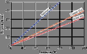
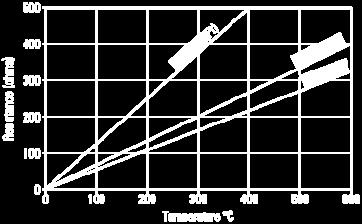
26 MEASURING OF TEMPERATURE USING R.T.D AIM: To measure the temperature by using resistance temperature detector. APPARATUS: Resistance temperature detector (R.T.D), Digital panel meter, Heater and container, Thermometer THEORY: The principle of operation of R.T.D. is based as fact that the electrical resistance of many metals increase almost directly with temperature and is reproducable to a high degree of accuracy. The resistance of the R.T.D. increase as temperature increase. The resistance and temperature linearly relateed over a wide temperature range. The main parts of R.T.D. is i. A glass or metal tube which houses a ceramic mandrel on which a platinum resistance wire is wound. The lead wires of the sensing element projected out of the ceramic mandrel. This arrangement becomes the resistance thermometer. ii. The glass or metal bulb is evacuated or filled with inert gas to protect the resistance wire sensing element. BASIC PRINCIPLE: When an electric conductor is subjected to temperature change, the resistance of the conductor changes.thus, the change in resistance of the electric conductor becomes a measure of the change in temperature when calibrated.
27 PROCEDURE: 1. Keep switch SW 2 in position marked TEMP 2. Connect a precision resistance of 100 ohms across input terminals 3. Adjust pot marked MIN (P 2 ) to read 0.0 on DPM. This action simulates ice-bath temperature. Since at zero degree centigrade PT 100 exhibits 100 ohms. 4. Now connect a precision resistance of 139 ohms across the input terminals. Adjust MAX pot (P 1 ) to read on DPM. This action simulates boiling point temperature of water i.e.100 degree centigrade.
28 5. Connect the R.T.D. across the terminals marked input. Note that polarity is immaterial. 6. Connect terminals marked output to DPM input terminals. 7. Note that RTD may be immersed in the boiling water and the resistance of the transducer should be noted down. 8. Note down the readings of the thermometer and RTD. OBSERVATIONS: S.No Thermometer Temperature on Resistance on Percentage reading ( o c) DPM ( o c) DPM (ohms) Error Please note that RTD exhibits good linearity and good accuracy in comparison with thermocouple The time constant of the sensor is large Polarity of connections is immaterial as RTD is only a resistance sensor. PRECAUTIONS: Make the connections properly. Take the readings when they are steady. RTD should not touch the bottom of the vessal. Please handle RTD very carefully as it is very costly. Please ensure that is not dropped on the floor. GRAPH: Thermometer temperature vs RTD temperature Thermometer temperature vs RTD Resistance
29 RESULT:
30 DISPLACEMENT MEASUREMENT - LDR
31 DISPLACEMENT MEASUREMENT LIGHT DEPENDENT RESISTOR AIM: Measurement of displacement using light dependent resistor. APPARATUS: Light Dependent Resistor (LDR), DPM THEORY: If radiation falls on a semiconductor, its conductivity increases. This is called as photo conductive effect. This effect is the basis of operation of L.D.R. The conductivity of a material is proportional to the concentration of charge carriers present. Radiant energy supplied to the semi conductor causes covalent bonds to be broken & hole and electron pairs in excess of those generated thermally, are created.these increased current carriers decrease the resistance of the material and hence, such a device is called as photo resistor, photoconductor or L.D.R. The L.D.R, with widest application, is the cadmium sulphide cell. Cd S photoconductors have high dissipation capability, excellent sensitivity in the visible spectrum and low resistance when stimulated by light. In this set up the L.D.R is used as a displacement transducer.
32 OPERATION: 1. Establish a connection between the lamp and front panel socket for lamp supply 2. Connect the L.D.R to the input terminals on the front panel. Polarity is not important. 3. Connect the output terminals of transducer circuit to D.P.M observing polarity. 4. Adjust the channel on which L.D.R is mounted, so that full scale deflection is obtained on the meter. If required, use potentiometer marked MAX. on the panel. 5. Using the scale mounted on the bottom of C channel, measure the input displacement & the resultant DPM readings.
33 OBSERVATIONS Sr.No Scale reading on the set up Effective displacement D.P.M indication Percentage Error THE STUDENT MAY NOTE THAT The set up can be used to measure displacement over a wide range. How ever over a limited range the response is seen to be linear. The L.D.R is sensitive to temperature variation also. Hence at different temperatures, the out put-input responses are seen to be slightly changing. PRECAUTIONS: Do not expose the L.D.R to intense light. Do not connect the DPM before connecting lamp and L.D.R to the front panel.
34 GRAPH: Plot the graph between input Displacement vs DPM Reading RESULT:
INSTRUMENTATION ECE Fourth Semester. Presented By:- Sumit Grover Lect., Deptt. of ECE
 INSTRUMENTATION ECE Fourth Semester Presented By:- Sumit Grover Lect., Deptt. of ECE Detailed Contents Objectives Sensors and transducer Classification of transducers Temperature transducers Resistance
Part 2. Sensor and Transducer Instrument Selection Criteria (3 Hour)
") Part 2 Sensor and Transducer Instrument Selection Criteria (3 Hour) At the end of this chapter, you should be able to: Describe the definition of sensor and transducer Determine the specification of control
Part 2 Sensor and Transducer Instrument Selection Criteria (3 Hour) At the end of this chapter, you should be able to: Describe the definition of sensor and transducer Determine the specification of control
Control Engineering BDA30703
 Control Engineering BDA30703 Lecture 4: Transducers Prepared by: Ramhuzaini bin Abd. Rahman Expected Outcomes At the end of this lecture, students should be able to; 1) Explain a basic measurement system.
ECNG3032 Control and Instrumentation I
 sensor ECNG3032 Control and Instrumentation I Lecture 1 Temperature Sensors Sensors The sensor is the first element in the measurement system. Measurand Transducer Principle Excitation Signal Interface
15. Compare the result with the value you have taken above Compare the calculated pressure value with the actual pressure value that you have
 105) to convert it to. 15. Compare the result with the value you have taken above. 17. 16. Compare the calculated pressure value with the actual pressure value that you have taken from the, is it the same?
MCT151: Introduction to Mechatronics Lecture 10: Sensors & Transduction Mechanisms
 Faculty of Engineering MCT151: Introduction to Mechatronics Lecture 10: Sensors & Transduction Mechanisms Slides are borrowed from Dr. Mohamed Elshiekh lectures Types of sensors Sensors are considered
Transducer. A device to which change or converts physical quantity in a more easily measurable quantity. Transducer. (Input) Sensor.
 Sensor.") Transducer A device to which change or converts physical quantity in a more easily measurable quantity Transducer (Input) Sensor (Output) Actuator Sensor A device which senses and detects the physical
Transducer A device to which change or converts physical quantity in a more easily measurable quantity Transducer (Input) Sensor (Output) Actuator Sensor A device which senses and detects the physical
LABORATORY MANUAL MEASUREMENTS & INSTRUMENTATION (ME- 318-F)
") LABORATORY MANUAL MEASUREMENTS & INSTRUMENTATION (ME- 318-F) LIST OF THE EXPERIMENT S. NO. NAME OF THE EXPERIMENT PAGE NO FROM TO 1. To measure stress and strain using strain gauge mounted on a cantilever
LABORATORY MANUAL MEASUREMENTS & INSTRUMENTATION (ME- 318-F) LIST OF THE EXPERIMENT S. NO. NAME OF THE EXPERIMENT PAGE NO FROM TO 1. To measure stress and strain using strain gauge mounted on a cantilever
Unit 57: Mechatronic System
 Unit 57: Mechatronic System Unit code: F/60/46 QCF level: 4 Credit value: 5 OUTCOME 2 TUTORIAL 2 - SENSOR TECHNOLOGIES 2 Understand electro-mechanical models and components in mechatronic systems and products
ECE421: Electronics for Instrumentation MEP382: Design of Applied Measurement Systems Lecture #2: Transduction Mechanisms
 ECE421: Electronics for Instrumentation MEP382: Design of Applied Measurement Systems Lecture #2: Transduction Mechanisms Mostafa Soliman, Ph.D. April 28 th 2014 Slides are borrowed from Dr. Moahmed Elshiekh
Slide 1. Temperatures Light (Optoelectronics) Magnetic Fields Strain Pressure Displacement and Rotation Acceleration Electronic Sensors
 Magnetic Fields Strain Pressure Displacement and Rotation Acceleration Electronic Sensors") Slide 1 Electronic Sensors Electronic sensors can be designed to detect a variety of quantitative aspects of a given physical system. Such quantities include: Temperatures Light (Optoelectronics) Magnetic
Slide 1 Electronic Sensors Electronic sensors can be designed to detect a variety of quantitative aspects of a given physical system. Such quantities include: Temperatures Light (Optoelectronics) Magnetic
Transducers. EEE355 Industrial Electronics
 Transducers EEE355 Industrial Electronics 1 Terminology Transducers convert one form of energy into another Sensors/Actuators are input/output transducers Sensors can be passive (e.g. change in resistance)
SENSORS AND TRANSDUCERS
 Electrical Measurements International Program Department of Electrical Engineering UNIVERSITAS INDONESIA ANDRITTO ABDUL GHAFFAR ANDHIKA ADIEL INSANI Lecturer : Ir. Chairul Hudaya, ST, M.Eng., Ph.D., IPM
1 Written and composed by: Prof. Muhammad Ali Malik (M. Phil. Physics), Govt. Degree College, Naushera
, Govt. Degree College, Naushera") CURRENT ELECTRICITY Q # 1. What do you know about electric current? Ans. Electric Current The amount of electric charge that flows through a cross section of a conductor per unit time is known as electric
CURRENT ELECTRICITY Q # 1. What do you know about electric current? Ans. Electric Current The amount of electric charge that flows through a cross section of a conductor per unit time is known as electric
I. MEASUREMENT OF TEMPERATURE
 I. MEASUREMENT OF TEMPERATURE Most frequent measurement and control Direct contact: thermometer, Indirect contact: pyrometer (detect generated heat or sensing optical properties) 1. Definition of temperature
Measurements in Mechatronic design. Transducers
 Measurements in Mechatronic design Transducers Quantities Current Voltage Torque Force Magnetic flux Distance Temperature Measurement system Physical quanties Transducer Signal conditioning Measurement
Force and Displacement Measurement
 Force and Displacement Measurement Prof. R.G. Longoria Updated Fall 20 Simple ways to measure a force http://scienceblogs.com/dotphysics/200/02/diy_force_probe.php Example: Key Force/Deflection measure
Resistance : R = ρ( ) units are Ohms ( 14 ) Resistor 100 ohms
 units are Ohms ( 14 ) Resistor 100 ohms") Resistance : If we look a little more closely into how charge flows in a conductor, we see that the electron is essentially free to move about the metal conductor material. The electron roams about the
Resistance : If we look a little more closely into how charge flows in a conductor, we see that the electron is essentially free to move about the metal conductor material. The electron roams about the
EET LAB MANUAL. Term-062 UNIVERSITY DIPLOMA PROGRAM ELECTRONIC EQUIPMENT MAINTENANCE
 UNIVERSITY DIPLOMA PROGRAM ELECTRONIC EQUIPMENT MAINTENANCE EET - 027 ELECTRONICS INSTRUMENTATION LAB MANUAL Term-062 Lab Instructor MUHAMMAD AJMAL KHAN Lecturer Electrical Engineering Department Copyright
PhysicsAndMathsTutor.com
 Electricity May 02 1. The graphs show the variation with potential difference V of the current I for three circuit elements. PhysicsAndMathsTutor.com When the four lamps are connected as shown in diagram
1. Distinguish the important characteristics of instrument that are totally electrical and totally electronic in nature. [16]
![1. Distinguish the important characteristics of instrument that are totally electrical and totally electronic in nature. [16]](/thumbs/96/127822274.jpg "1. Distinguish the important characteristics of instrument that are totally electrical and totally electronic in nature. [16]") Code No: RR320204 Set No. 1 1. Distinguish the important characteristics of instrument that are totally electrical and totally electronic in nature. [16] 2. Distinguish between deterministic signals and
Code No: RR320204 Set No. 1 1. Distinguish the important characteristics of instrument that are totally electrical and totally electronic in nature. [16] 2. Distinguish between deterministic signals and
THERMOCOUPLE CHARACTERISTICS TRAINER
 THERMOCOUPLE CHARACTERISTICS TRAINER (Model No : ) User Manual Version 2.0 Technical Clarification /Suggestion : / Technical Support Division, Vi Microsystems Pvt. Ltd., Plot No :75,Electronics Estate,
ELECTRICAL MEASUREMENTS LAB MANUAL
 ELECTRICAL MEASUREMENTS LAB MANUAL Prepared by B.SAIDAMMA R13 Regulation Any 10 of the following experiments are to be conducted 1. Calibration and Testing of single phase energy Meter 2. Calibration of
CHAPTER 5. BRIDGES AND THEIR APPLICATION Resistance Measurements. Dr. Wael Salah
 CHAPTER 5 BRIDGES AND THEIR APPLICATION Resistance Measurements 1 RESISTANCE MEASUREMENTS Conventional Ways of Measuring Resistance:- 1) Using a Ohmmeter Convenient but inaccurate, requires calibration
COURSE OF Prepared By: MUHAMMAD MOEEN SULTAN Department of Mechanical Engineering UET Lahore, KSK Campus
 COURSE OF Active and passive instruments Null-type and deflection-type instruments Analogue and digital instruments In active instruments, the external power source is usually required to produce an output
Sensors and Transducers. mywbut.com
 Sensors and Transducers 1 Objectives At the end of this chapter, the students should be able to: describe the principle of operation of various sensors and transducers; namely.. Resistive Position Transducers.
SENSORS and TRANSDUCERS
 SENSORS and TRANSDUCERS Tadeusz Stepinski, Signaler och system The Thermal Energy Domain Physics» Seebeck effect» Peltier effect» Thomson effect Thermal effects in semiconductors Thermoelectric sensors
National 5 Physics. Electricity and Energy. Notes
 National 5 Physics Electricity and Energy Notes Name. 1 P a g e Key Area Notes, Examples and Questions Page 3 Conservation of energy Page 10 Electrical charge carriers and electric fields and potential
e453.eps 1 Change (or the absolute value) in the measured physical variable 2 Change in the sensor property is translated into low-power-level
 in the measured physical variable 2 Change in the sensor property is translated into low-power-level") 3 Basic Phenomenon in Effect in Sensor Operation Sensors Prof. Dr. M. Zahurul Haq zahurul@me.buet.ac.bd http://teacher.buet.ac.bd/zahurul/ Department of Mechanical Engineering Bangladesh University of
3 Basic Phenomenon in Effect in Sensor Operation Sensors Prof. Dr. M. Zahurul Haq zahurul@me.buet.ac.bd http://teacher.buet.ac.bd/zahurul/ Department of Mechanical Engineering Bangladesh University of
Industrial Instrumentation Prof. Alok Barua Department of Electrical Engineering Indian Institute of Technology - Kharagpur
 Industrial Instrumentation Prof. Alok Barua Department of Electrical Engineering Indian Institute of Technology - Kharagpur Lecture - 9 Resistance Temperature Detector Welcome to the lesson 9 of Industrial
Harnessing the Power of Arduino for the Advanced Lab
 P P Herbert Jaeger + Harnessing the Power of Arduino for the Advanced Lab (Final Version) ALPhA Immersion Workshop July 27 29, 2017 Department of Physics Indiana University Purdue University Ft. Wayne,
Temperature Measurement
 MECE 3320 Measurements & Instrumentation Temperature Measurement Dr. Isaac Choutapalli Department of Mechanical Engineering University of Texas Pan American Introduction Temperature is one of the most
ENSC387: Introduction to Electromechanical Sensors and Actuators LAB 3: USING STRAIN GAUGES TO FIND POISSON S RATIO AND YOUNG S MODULUS
 ENSC387: Introduction to Electromechanical Sensors and Actuators LAB 3: USING STRAIN GAUGES TO FIND POISSON S RATIO AND YOUNG S MODULUS 1 Introduction... 3 2 Objective... 3 3 Supplies... 3 4 Theory...
ME 515 Mechatronics. Overview of Computer based Control System
 ME 515 Mechatronics Introduction to Sensors I Asanga Ratnaweera Department of Faculty of Engineering University of Peradeniya Tel: 081239 (3627) Email: asangar@pdn.ac.lk Overview of Computer based Control
VALLIAMMAI ENGINEERING COLLEGE
 VALLIAMMAI ENGINEERING COLLEGE SRM Nagar, Kattankulathur 603 203 DEPARTMENT OF ELECTRONICS AND INSTRUMENTATION ENGINEERING QUESTION BANK V SEMESTER EI6502 -INDUSTRIAL INSTRUMENTATION I Regulation 2013
Measurements & Instrumentation. Module 3: Temperature Sensors
 Measurements & Instrumentation PREPARED BY Academic Services Unit August 2013 Institute of Applied Technology, 2013 Module Objectives Upon successful completion of this module, students should be able
Unit 3 Transducers. Lecture_3.1 Introduction to Transducers
 Unit 3 Transducers Lecture_3.1 Introduction to Transducers Introduction to transducers A transducer is a device that converts one form of energy to other form. It converts the measurand to a usable electrical
NTC Thermistors [From Philips Data Handbook PA ]
![NTC Thermistors [From Philips Data Handbook PA ]](/thumbs/72/67578653.jpg "NTC Thermistors [From Philips Data Handbook PA ]") NTC Thermistors [From Philips Data Handbook PA02 1989] Definition and composition Negative temperature coefficient thermistors (NTCs) are resistive components, of which the resistance decreases as temperature
NTC Thermistors [From Philips Data Handbook PA02 1989] Definition and composition Negative temperature coefficient thermistors (NTCs) are resistive components, of which the resistance decreases as temperature
Prof. S.K. Saha. Sensors 1. Lecture 5 June 11, Prof. S.K. Saha. Purpose Classification Internal Sensors. External Sensors.
 Lecture 5 June 11, 2009 Sensors Prof. S.K. Saha Dept. of Mech. Eng. IIT Delhi Announcement Outlines of slides in Lectures 1-4 on May 15, 18, 21, June 01, 2009, respectively, are available from: http://web.iitd.ac.in/~saha/
Transducers. ME 3251 Thermal Fluid Systems
 Transducers ME 3251 Thermal Fluid Systems 1 Transducers Transform values of physical variables into equivalent electrical signals Converts a signal from one form to another form 2 Types of Transducers
III B.Tech. II Semester Regular Examinations, April/May INSTRUMENTATION & CONTROL SYSTEMS (Mechanical Engineering) Time: 3 Hours Max Marks: 75
 Time: 3 Hours Max Marks: 75") R10 Set No: 1 1. (a) Distinguish between accuracy and Precision. Which of these is more desirable during the act of measurement and why? (b) Discuss the necessity and importance of dynamic performance
R10 Set No: 1 1. (a) Distinguish between accuracy and Precision. Which of these is more desirable during the act of measurement and why? (b) Discuss the necessity and importance of dynamic performance
Electron Theory. Elements of an Atom
 Electron Theory Elements of an Atom All matter is composed of molecules which are made up of a combination of atoms. Atoms have a nucleus with electrons orbiting around it. The nucleus is composed of protons
STRAIN GAUGES YEDITEPE UNIVERSITY DEPARTMENT OF MECHANICAL ENGINEERING
 STRAIN GAUGES YEDITEPE UNIVERSITY DEPARTMENT OF MECHANICAL ENGINEERING 1 YEDITEPE UNIVERSITY ENGINEERING FACULTY MECHANICAL ENGINEERING LABORATORY 1. Objective: Strain Gauges Know how the change in resistance
Mechatronics II Laboratory EXPERIMENT #1: FORCE AND TORQUE SENSORS DC Motor Characteristics Dynamometer, Part I
 Mechatronics II Laboratory EXPEIMENT #1: FOCE AND TOQUE SENSOS DC Motor Characteristics Dynamometer, Part I Force Sensors Force and torque are not measured directly. Typically, the deformation or strain
Summary Notes ALTERNATING CURRENT AND VOLTAGE
 HIGHER CIRCUIT THEORY Wheatstone Bridge Circuit Any method of measuring resistance using an ammeter or voltmeter necessarily involves some error unless the resistances of the meters themselves are taken
An ion follows a circular path in a uniform magnetic field. Which single change decreases the radius of the path?
 T5-1 [237 marks] 1. A circuit is formed by connecting a resistor between the terminals of a battery of electromotive force (emf) 6 V. The battery has internal resistance. Which statement is correct when
EXPERIMENT ET: ENERGY TRANSFORMATION & SPECIFIC HEAT
 MASSACHUSETTS INSTITUTE OF TECHNOLOGY Physics Department Physics 8.01X Fall 2000 EXPERIMENT ET: ENERGY TRANSFORMATION & SPECIFIC HEAT We have introduced different types of energy which help us describe
Strain Gauge Application and Measurement of Unknown Load
 University Diploma Program Electronic Equipment Maintenance Lab Instructor: Muhammad Ajmal Khan EET-027, Experiment # 6 Strain Gauge Application and Measurement of Unknown Load Objectives: 1. To find the
ELECTRICITY AND MAGNETISM, A. C. THEORY AND ELECTRONICS, ATOMIC AND NUCLEAR PHYSICS
 UNIT 2: ELECTRICITY AND MAGNETISM, A. C. THEORY AND ELECTRONICS, ATOMIC AND NUCLEAR PHYSICS MODULE 1: ELECTRICITY AND MAGNETISM GENERAL OBJECTIVES On completion of this Module, students should: 1. understand
Subject: BT6008 Process Measurement and Control. The General Control System
 WALJAT COLLEGES OF APPLIED SCIENCES In academic partnership with BIRLA INSTITUTE OF TECHNOLOGY Question Bank Course: Biotechnology Session: 005-006 Subject: BT6008 Process Measurement and Control Semester:
Calculate the total resistance of this combination. (3)
") 1 The circuit shows a combination of three resistors. 22 Ω 47 Ω 620 Ω Calculate the total resistance of this combination. Total resistance = (Total for Question = 3 marks) 2 (a) Sketch a graph to show
1 The circuit shows a combination of three resistors. 22 Ω 47 Ω 620 Ω Calculate the total resistance of this combination. Total resistance = (Total for Question = 3 marks) 2 (a) Sketch a graph to show
International Journal of Scientific & Engineering Research, Volume 5, Issue 1, January ISSN
 International Journal of Scientific & Engineering Research, Volume 5, Issue 1, January-214 29 An Experimental Analysis of Stress Relaxation in Nonwoven Fabrics Sajid Ahmed Qureshi ABSTRACT - The current
PLANCK S CONSTANT IN THE LIGHT OF AN INCANDESCENT LAMP
 PLANCK S CONSTANT IN THE LIGHT OF AN INCANDESCENT LAMP In 1900 Planck introduced the hypothesis that light is emitted by matter in the form of quanta of energy hν. In 1905 Einstein extended this idea proposing
Varuvan Vadivelan. Institute of Technology LAB MANUAL. : 2013 : B.E. MECHANICAL ENGINEERING : III Year / V Semester. Regulation Branch Year & Semester
 Varuvan Vadivelan Institute of Technology Dharmapuri 636 703 LAB MANUAL Regulation Branch Year & Semester : 2013 : B.E. MECHANICAL ENGINEERING : III Year / V Semester ME 6511 - DYNAMICS LABORATORY GENERAL
WIND POWER AND ITS METROLOGIES
 Problem Wind Power and Its Metrologies Experimental Question 1 page 1 of 14 WIND POWER AND ITS METROLOGIES I. APPARATUS Figure 1. Overall setup 1. Wind tunnel with nichrom (nickel-chromium) wire 2. Computer
Revision Guide for Chapter 2
 Revision Guide for Chapter 2 Contents Student s Checklist Revision Notes Electric current and charge... 5 Potential difference... 5 Conductance and resistance... 6 Parallel circuit... 7 Series circuit...
The secondary winding have equal no. of turns. The secondary windings are placed identically on either side of the primary winding.
 UNIT 4 DISPLACEMENT MEASURMENT Electrical comparator Working principle of Electrical comparators: These instruments are based on the theory of Wheatstone A.C. Bridge. When the bridge is electrically balanced,
2. (a) Differentiate between rare metal thermocouples and base metal thermocouples.
 Differentiate between rare metal thermocouples and base metal thermocouples.") Code No: R05410304 Set No. 1 1. (a) Distinguish between direct and indirect methods of measurement with suitable examples. (b) What are desired, modifying and interfering inputs for an instrumentation
Code No: R05410304 Set No. 1 1. (a) Distinguish between direct and indirect methods of measurement with suitable examples. (b) What are desired, modifying and interfering inputs for an instrumentation
Module I Module I: traditional test instrumentation and acquisition systems. Prof. Ramat, Stefano
 Preparatory Course (task NA 3.6) Basics of experimental testing and theoretical background Module I Module I: traditional test instrumentation and acquisition systems Prof. Ramat, Stefano Transducers A
1. Mark the correct statement(s)
") 1. Mark the correct statement(s) Figure to the right shows a mass measurement scale using a spring. 1.1 The span of the scale is a) 16 kg b) 21 kg c) 11 kg d) 5-16 kg 1.2 The range of the scale is a) 16
1. Mark the correct statement(s) Figure to the right shows a mass measurement scale using a spring. 1.1 The span of the scale is a) 16 kg b) 21 kg c) 11 kg d) 5-16 kg 1.2 The range of the scale is a) 16
Farr High School HIGHER PHYSICS. Unit 3 Electricity. Question Booklet
 Farr High School HIGHER PHYSICS Unit 3 Electricity Question Booklet 1 MONITORING ND MESURING.C. 1. What is the peak voltage of the 230 V mains supply? The frequency of the mains supply is 50 Hz. How many
Process Control Instrumentation Technology Curtis D. Johnson Eighth Edition
 Process Control Instrumentation Technology Curtis D. Johnson Eighth Edition Pearson Education Limited Edinburgh Gate Harlow Essex CM20 2JE England and Associated Companies throughout the world Visit us
Objective Type Questions Instrumentation System & Devices (IDS)
") 1. A balance beam scale uses which of the following units? a. grams b.pounds c. ounces d. kilograms 2. Which of the following would be about the height of the average doorway? a. 2 meters b. 2 centimeters
1. A balance beam scale uses which of the following units? a. grams b.pounds c. ounces d. kilograms 2. Which of the following would be about the height of the average doorway? a. 2 meters b. 2 centimeters
Solar Flat Plate Thermal Collector
 Solar Flat Plate Thermal Collector INTRODUCTION: Solar heater is one of the simplest and basic technologies in the solar energy field. Collector is the heart of any solar heating system. It absorbs and
1 Fig. 3.1 shows the variation of the magnetic flux linkage with time t for a small generator. magnetic. flux linkage / Wb-turns 1.
 1 Fig. 3.1 shows the variation of the magnetic flux linkage with time t for a small generator. 2 magnetic 1 flux linkage / 0 10 2 Wb-turns 1 2 5 10 15 t / 10 3 s Fig. 3.1 The generator has a flat coil
Lecture - 2A Instruments-I
 Engineering Metrology Prof. J. Ramkumar Department of Mechanical Engineering & Design Programme Indian Institute of Technology, Kanpur Dr. Amandeep Singh Oberoi Department of Industrial & Production Engineering
Module 3 Electrical Fundamentals
 3.1 Electron Theory Structure and distribution of electrical charges within: atoms, molecules, ions, compounds; Molecular structure of conductors, semiconductors and insulators. 3.2 Static Electricity
VTU NOTES QUESTION PAPERS NEWS RESULTS FORUMS Fig. 1 Data acquisition block diagram
 UNIT 7: Transducers: Classification and selection of transducers. Strain gauges. LVDT. Measurement of temperature and pressure. Photo-conductive and photo-voltaic cells. 06 Hours Nearly all engineering
Physics Department. CfE Higher Unit 3: Electricity. Problem Booklet
 Physics Department CfE Higher Unit 3: Electricity Problem Booklet Name Class 1 Contents Exercise 1: Monitoring and measuring a.c. Exercise 2: Current, voltage, power and resistance Exercise 3: Electrical
Physics 102 Spring 2007: Final Exam Multiple-Choice Questions
 Last Name: First Name: Physics 102 Spring 2007: Final Exam Multiple-Choice Questions 1. The circuit on the left in the figure below contains a battery of potential V and a variable resistor R V. The circuit
Lab 1: Determination of e/m for the electron
 Lab 1: Determination of e/m for the electron Background Reading: Tipler, Llewellyn pp. 125 130; this covers the original method of Thomson which is somewhat different from that used in this experiment
PHY222 Lab 8 - Magnetic Fields and Right Hand Rules Magnetic forces on wires, electron beams, coils; direction of magnetic field in a coil
 PHY222 Lab 8 - Magnetic Fields and Right Hand Rules Magnetic forces on wires, electron beams, coils; direction of magnetic field in a coil Print Your Name Print Your Partners' Names You will return this
RADIO AMATEUR EXAM GENERAL CLASS
 RAE-Lessons by 4S7VJ 1 CHAPTER- 2 RADIO AMATEUR EXAM GENERAL CLASS By 4S7VJ 2.1 Sine-wave If a magnet rotates near a coil, an alternating e.m.f. (a.c.) generates in the coil. This e.m.f. gradually increase
REPORT ON TRANSDUCERS TRANSDUCERS
 REPORT ON TRANSDUCERS TRANSDUCERS DEFINITIONS: TRANSDUCER A transducer is a device, usually electrical, electronic, electro-mechanical, electromagnetic, photonic, or photovoltaic that converts one type
DUBLIN INSTITUTE OF TECHNOLOGY Kevin Street, Dublin 8.
 Question Sheet Page 1 of 5 Instructions for the student: Question 1 is compulsory [40 marks] Attempt any two other questions [30 marks per question] The following must be made available during the examination:
National Exams May 2016
 National Exams May 2016 04-Agric-A5, Principles of Instrumentation 3 hours duration NOTES: 1. If doubt exists as to the interpretation of any question, the candidate is urged to submit with the answer
MAHARASHTRA STATE BOARD OF TECHNICAL EDUCATION (Autonomous) (ISO/IEC Certified) Subject Code : Page No: 1/
 (ISO/IEC Certified) Subject Code : Page No: 1/") MAHARASHTRA STATE BOARD OF TECHNICAL EDUCATION (Autonomous) (ISO/IEC 27001 2005 Certified) SUMMER 14 EXAMINATION Model Answer Subject Code : 17434 Page No: 1/ Important Instructions to examiners: 1) The
MAHARASHTRA STATE BOARD OF TECHNICAL EDUCATION (Autonomous) (ISO/IEC 27001 2005 Certified) SUMMER 14 EXAMINATION Model Answer Subject Code : 17434 Page No: 1/ Important Instructions to examiners: 1) The
INSTITUTE OF AERONAUTICAL ENGINEERING (Autonomous) Dundigal, Hyderabad
 Dundigal, Hyderabad") INSTITUTE OF AERONAUTICAL ENGINEERING (Autonomous) Dundigal, Hyderabad -500 043 MECHANICAL ENGINEERING TUTORIAL QUESTION BANK Name : INSTRUMENTATION AND CONTROL SYSTEMS Code : A70343 Class : IV B. Tech
INSTITUTE OF AERONAUTICAL ENGINEERING (Autonomous) Dundigal, Hyderabad -500 043 MECHANICAL ENGINEERING TUTORIAL QUESTION BANK Name : INSTRUMENTATION AND CONTROL SYSTEMS Code : A70343 Class : IV B. Tech
UNIT II CURRENT ELECTRICITY
 UNIT II CUENT ELECTICITY Weightage : 07 Marks Electric current; flow of electric charges in a metllic conductor, drift velocity, mobility and their relation with electric current. Ohm s law electrical
NZQA unit standard version 2 Page 1 of 8
 Page 1 of 8 Title Demonstrate knowledge of electrical principles in an electrotechnology or telecommunications environment Level 3 Credits 15 Purpose This unit standard covers basic electrical principles
ME 365 EXPERIMENT 5 FIRST ORDER SYSTEM IDENTIFICATION APPLIED TO TEMPERATURE MEASUREMENT SYSTEMS
 ME 365 EXPERIMENT 5 FIRST ORDER SYSTEM IDENTIFICATION APPLIED TO TEMPERATURE MEASUREMENT SYSTEMS Objectives: In this two week experiment, we will gain familiarity with first order systems by using two
AP Physics C - E & M
 AP Physics C - E & M Current and Circuits 2017-07-12 www.njctl.org Electric Current Resistance and Resistivity Electromotive Force (EMF) Energy and Power Resistors in Series and in Parallel Kirchoff's
EXEMPLAR NATIONAL CERTIFICATE (VOCATIONAL) ELECTRICAL PRINCIPLES AND PRACTICE NQF LEVEL 3 ( ) (X-Paper) 09:00 12:00
 ELECTRICAL PRINCIPLES AND PRACTICE NQF LEVEL 3 ( ) (X-Paper) 09:00 12:00") NATIONAL CERTIFICATE (VOCATIONAL) ELECTRICAL PRINCIPLES AND PRACTICE NQF LEVEL 3 2008 (12041002) (X-Paper) 09:00 12:00 EXEMPLAR This question paper consists of 7 pages. EXEMPLAR -2- NC(V) TIME: 3 HOURS
NATIONAL CERTIFICATE (VOCATIONAL) ELECTRICAL PRINCIPLES AND PRACTICE NQF LEVEL 3 2008 (12041002) (X-Paper) 09:00 12:00 EXEMPLAR This question paper consists of 7 pages. EXEMPLAR -2- NC(V) TIME: 3 HOURS
Lab 4: The Classical Hall Effect
 Lab 4: The Classical Hall Effect Background A particle with charge q moving with a velocity v in a uniform magnetic field B will experience a force F, F = q( v B ) (1) 1 Introduction Understanding the
NATIONAL QUALIFICATIONS CURRICULUM SUPPORT. Physics. Electricity. Questions and Solutions. James Page Arthur Baillie [HIGHER]
![NATIONAL QUALIFICATIONS CURRICULUM SUPPORT. Physics. Electricity. Questions and Solutions. James Page Arthur Baillie [HIGHER]](/thumbs/86/93982339.jpg "NATIONAL QUALIFICATIONS CURRICULUM SUPPORT. Physics. Electricity. Questions and Solutions. James Page Arthur Baillie [HIGHER]") NTIONL QULIFICTIONS CURRICULUM SUPPORT Physics Electricity Questions and Solutions James Page rthur Baillie [HIGHER] The Scottish Qualifications uthority regularly reviews the arrangements for National
NTIONL QULIFICTIONS CURRICULUM SUPPORT Physics Electricity Questions and Solutions James Page rthur Baillie [HIGHER] The Scottish Qualifications uthority regularly reviews the arrangements for National
ISSPRO 3 3/8 Programmable Tachometer High Performance EV Line Part Numbers R5535M, R6535M
 General Information: I n c o r p o r a t e d ISSPRO 3 3/8 Programmable Tachometer High Performance EV Line Part Numbers R5535M, R6535M ISSPRO, INC. 2515 N.E. Riverside Way, Portland OR 97211 Telephone:
On the axes of Fig. 4.1, carefully sketch a graph to show how the potential difference V across the capacitor varies with time t. Label this graph L.
 1 (a) A charged capacitor is connected across the ends of a negative temperature coefficient (NTC) thermistor kept at a fixed temperature. The capacitor discharges through the thermistor. The potential
Resistivity and Temperature Coefficients (at 20 C)
") Homework # 4 Resistivity and Temperature Coefficients (at 0 C) Substance Resistivity, Temperature ( m) Coefficient, (C ) - Conductors Silver.59 x 0-0.006 Copper.6 x 0-0.006 Aluminum.65 x 0-0.0049 Tungsten
Homework # 4 Resistivity and Temperature Coefficients (at 0 C) Substance Resistivity, Temperature ( m) Coefficient, (C ) - Conductors Silver.59 x 0-0.006 Copper.6 x 0-0.006 Aluminum.65 x 0-0.0049 Tungsten
Q11: WHAT IS A MEANT GOOD ELECTRICAL CONNECTION?
 Q1. How to check for zero error in a: (i) Vernier caliper (ii) Micrometer screw gauge (iii) Meter rule (iv) Stopwatch Ans: (i) Close the jaws of the vernier caliper fully. When the zeros of both MAIN SCALE
Experiment 3. Electrical Energy. Calculate the electrical power dissipated in a resistor.
 Experiment 3 Electrical Energy 3.1 Objectives Calculate the electrical power dissipated in a resistor. Determine the heat added to the water by an immersed heater. Determine if the energy dissipated by
A Review of Circuitry
 1 A Review of Circuitry There is an attractive force between a positive and a negative charge. In order to separate these charges, a force at least equal to the attractive force must be applied to one
ELECTRONIC SENSORS PREAMBLE. This note gives a brief introduction to sensors. The focus is. on sensor mechanisms. It describes in general terms how
 ELECTRONIC SENSORS PREAMBLE This note gives a brief introduction to sensors. The focus is on sensor mechanisms. It describes in general terms how sensors work. It covers strain gage sensors in detail.
Temperature. 3
 Temperature In 1848, Sir William Thomson (Lord Kelvin) stated the zero principle of dynamics. This principle enabled him to define thermodynamic temperature and to establish an objective method of measuring
The principles of conservation of energy and charge apply to electrical circuits. Properties of magnetic fields apply in nature and technology.
 UIT E UMMARY KEY COCEPT CHAPTER UMMARY 11 The principles of conservation of energy and charge apply to electrical circuits. Electrical circuits Conventional current and electron flow Current, electrical
5.2 Other experimental problems and demonstrations
 5.2 Other experimental problems and demonstrations In the earlier section of this chapter, we have described a specimen experimental problem and its demonstration in detail. We feel that it is not necessary
CEE575 - Homework 1. Resistive Sensing: Due Monday, January 29
 CEE575 - Homework 1 Resistive Sensing: Due Monday, January 29 Problem 1: Planes A metallic wire embedded in a strain gage is 4 cm long with a diameter of 0.1 mm. The gage is mounted on the upper surface
Gurgaon TOPIC: ELECTROSTATIC Assignment 1 (2018)
") LJPS Class XII Gurgaon TOPIC: ELECTROSTATIC Assignment (08). A uniform electric field E exists between two charged plates as shown in figure. What would be the work done in moving a charge q along the
LJPS Class XII Gurgaon TOPIC: ELECTROSTATIC Assignment (08). A uniform electric field E exists between two charged plates as shown in figure. What would be the work done in moving a charge q along the
SECTION 3 BASIC AUTOMATIC CONTROLS UNIT 12 BASIC ELECTRICITY AND MAGNETISM
 SECTION 3 BASIC AUTOMATIC CONTROLS UNIT 12 BASIC ELECTRICITY AND MAGNETISM Unit Objectives Describe the structure of an atom. Identify atoms with a positive charge and atoms with a negative charge. Explain
e453.eps 1 Change (or the absolute value) in the measured physical variable 2 Change in the sensor property is translated into low-power-level
 in the measured physical variable 2 Change in the sensor property is translated into low-power-level") 3 Basic Phenomenon in Effect in Sensor Operation Measurement & Sensors Prof. Dr. M. Zahurul Haq http://teacher.buet.ac.bd/zahurul/ Department of Mechanical Engineering Bangladesh University of Engineering
3 Basic Phenomenon in Effect in Sensor Operation Measurement & Sensors Prof. Dr. M. Zahurul Haq http://teacher.buet.ac.bd/zahurul/ Department of Mechanical Engineering Bangladesh University of Engineering
Lecture 19. Measurement of Solid-Mechanical Quantities (Chapter 8) Measuring Strain Measuring Displacement Measuring Linear Velocity
 Measuring Strain Measuring Displacement Measuring Linear Velocity") MECH 373 Instrumentation and Measurements Lecture 19 Measurement of Solid-Mechanical Quantities (Chapter 8) Measuring Strain Measuring Displacement Measuring Linear Velocity Measuring Accepleration and
MECH 373 Instrumentation and Measurements Lecture 19 Measurement of Solid-Mechanical Quantities (Chapter 8) Measuring Strain Measuring Displacement Measuring Linear Velocity Measuring Accepleration and