AP Physics C - E & M
|
|
|
- Ferdinand Griffin
- 5 years ago
- Views:
Transcription

1


2 AP Physics C - E & M Current and Circuits
3 Electric Current Resistance and Resistivity Electromotive Force (EMF) Energy and Power Resistors in Series and in Parallel Kirchoff's Rules Circuit Measuring Devices RC Circuits Table of Contents: Current and Circuits Click on the topic to go to that section. Move any photo or image in this presentation to reveal a link to its source, providing attribution and additional information.
4 Electric Current Return to Table of Contents
5 Electric Current Electric Current is defined as the movement of charge from one region of space to another, and is denoted by a capital I. In conductors, electrons move around freely, not attached to any specific atom, but since they are going off in all different directions, the net current in any normal conductor such as copper would be zero. However if an electric field were passed through the copper wire, the free charges would begin to move in one specific direction resulting in a current.
6 Electric Current The net motion of these charges due to the force exerted by the Electric Field is called drift velocity, v d. Even though individual speeds of the electrons are on the order of 10 6 m/s, the random nature of their movement and their collisions with the other electrons and ions in the conductor, slow their drift velocity to 10-3 m/s. The Electric Field propagates at nearly the speed of light through the material, but the physical movement of the electrons is so much slower.
7 Electric Current _ + + Before Electric Field _ + _ _ + After Electric Field Once the Electric Field is turned on, there is a net force to the right on the positively charged particles, and a net force to the left on the negative particles. The negative charges (electrons) would actually move, and the positive charges (nuclei) would stay put.
8 Electric Current _ + + Before Electric Field _ + _ _ + After Electric Field Circuit Analysis defines current as the direction that positive charges move - conventional current. This is a legacy from Ben Franklin who assigned the negative quality to the charge left on the glass after being rubbed by silk. It should have been positive. Click here for an interesting article on this naming convention.
9 Electric Current Both positive and negative charges can generate an electric current, but only when they pass through certain materials. In metals only electrons can flow, but in ionized gases, such as plasma, both electrons and positive ions are able to flow.
10 Electric Current In the diagram above, positive charges are flowing through a specific area in a certain amount of time. The rate of flow of charges is defined as current and is represented as: The unit for current is coulombs/second, or ampere, named after Andre-Marie Ampere, a French physicist and mathematician.
11 Electric Current Find the rate at which charges are flowing through a cross sectional area of A. elementary charge volume that charge moves through charge increment number of elementary charges distance that charge moves through

12 Electric Current This results in another definition for electric current. And current density, J, which is the amount of current per area:
13 1 How long will it take for C of electric charge to pass through a copper wire if the current is measured to be 1.50 A? A s B 267 s C 534 s Answer D 600 s E 634 s
14 2 How many charge carriers are required to produce 1.50 A of current in a wire of radius 2.00 cm when the carriers have a drift velocity of 1.50 x 10⁻³ m/s? A 6.47 x B 9.87 x C 3.36 x Answer D 4.97 x E 9.46 x 10 24
15 Resistance and Resistivity Return to Table of Contents
16 Resistivity When a current is passing through a wire there is a resistance to the motion of the charges, as they bounce off other charges and atoms in the conductor. The resistance is directly proportional to the Electric Field created by the Electric Potential difference and inversely proportional to the current density. Materials have a unique value for the resistivity, ρ, with units of ohm-meters.
17 Resistivity The resistivity of a material is affected by its temperature. At higher temperatures, resistivity in a metal conductor increases. because as the material heats up, the particles within it begin to vibrate more. As a result the moving charged particles will collide more frequently with the ions decreasing the drift velocity, which decreases the current density. This equation is only valid up to about 373 K.


18 Ohm's Law We will use this micro property of the material of the conductor to derive the resistance of a conductor's physical dimensions to current flow. For a conductor of length l, assume that the Electric Field created by the Electric Potential is uniform: A is the cross sectional area of the conductor

19 Define Resistance as: Resistance and Ohm's Law Which leads to Ohm's Law: Resistance has the unit of ohm, Ω, which is volt/amp. Frequently it is written just as V = IR. Not all materials are described by Ohm's Law - the ones that do are called "ohmic" materials. There is not a linear relationship between Electric Potential and Current in semiconductors. Semiconductors are not ohmic materials.
20 3 What is the resistance of a copper wire with a length of 2.0 m, a radius of 5.0 cm and a resistivity of 1.7 x 10⁻⁸ Ω -m? A 9.6 x 10⁻⁷ Ω B 1.8 x 10⁻⁶ Ω C 2.6 x 10⁻⁶ Ω Answer D 3.8 x 10⁻⁶ Ω E 4.3 x 10⁻⁶ Ω
21 4 What is the resistance of a gold wire with a length of 0.50 m, a diameter of 6.0 cm and a resistivity of 2.8 x 10⁻⁸ Ω -m? A 1.2 x 10⁻⁶ Ω B 1.8 x 10⁻⁶ Ω C 5.0 x 10⁻⁶ Ω Answer D 6.1 x 10⁻⁶ Ω E 8.9 x 10⁻⁶ Ω
22 Electromotive Force (EMF) Return to Table of Contents
23 Electromotive Force A battery converts chemical energy into Electric Potential Energy, which will do work on a charge, increasing its energy and setting it in motion out of the positive terminal, heading for the negative terminal of the battery. As the charge goes through the circuit, it transfers its potential energy through the resistance in the wire into thermal energy. For DC circuits (the current only flows one way), it takes a while for an individual charge to get back to the battery (drift velocity is so small), but it "bumps" the charges in front of it, setting up a chain reaction of moving charges. This is analogous to the flow of water drops in a hose. Of course, its really the electrons that are moving about the circuit, but we're using the definition of conventional current here.
24 Electromotive Force When the charge gets back, it has a much lower potential energy than when it started its journey. The battery then gives it another boost of energy and it goes again. This is current. The Electric Field that is created by the difference in Electric Potential (The Electric Potential Energy per charge) between the two terminals of the battery propagates at nearly the speed of light (dependent on the conductor properties), while the electrons are moving much slower. When a light that is in a battery circuit is turned on, the light turns on almost instantaneously because it is not waiting for the charge from the battery terminal to get to the light.
25 Electromotive Force This Electric Potential Energy per charge is called Electromotive Force, or EMF or ε. This is clearly not a force, but the name is preserved for historical reasons. The full EMF is not always delivered to the circuit, since there is an internal resistance present within the battery. This is equivalent to when you studied mechanics, and friction would impact the acceleration of an object. In Electricity, resistance is analagous to friction. Model the battery as shown below: I An "ideal" battery would not have an internal resistance. r R I

26 Electromotive Force The physical battery is shown within the rectangle and includes the source of the EMF, ε, and r, which represents the internal resistance due to the materials and the chemical reaction occuring within the battery. r R If the switch is open, then no current is flowing, and a Voltmeter measuring the voltage across points a and b would read equal ε. This is called the terminal voltage.

27 Electromotive Force When the switch is closed, a current flows. This results in the terminal voltage being less than ε, and the current delivered to the circuit being less then ε/r, as one would have expected with a perfect battery. The internal resistance increases as the battery gets older and in cold weather. Both cases contribute to car batteries not being able to start a car in the winter. I r R I
28 Circuit Components Conducting Wire Resistor Ideal Battery (Source of EMF) Battery (Source of EMF with an internal resistance) A Ammeter V Voltmeter
29 5 A 9.0 V battery with an internal resistance of 1.5 Ω is connected in series to a light bulb with a resistance of 12 Ω. What is the current in the circuit? A A B 0.67 A C 0.71 A Answer D 0.75 A E 6.0 A
30 6 A 9.0 V battery with an internal resistance of 1.5 Ω is connected in series to a light bulb with a resistance of 12 Ω. What is the terminal voltage of the battery when current is flowing? A 0.08V B 0.96 V C 8.0 V Answer D 9.0 V E 10 V
31 Energy and Power Return to Table of Contents
32 Electrical Energy and Power A resistor's thermal energy increases when a current passes through it. The free electrons moving through the resistor bounce off each other and the atoms, increasing the velocity of the electrons and atoms. This increases the thermal energy, also of the resistor - the electrical energy provided by the battery is transferred into kinetic energy and then thermal energy of the resistor. The resistor transfers the increased thermal energy to the environment via conduction, conduction and radiation. The rate at which this energy is transferred is called power (like in mechanics).

33 Electrical Energy and Power Calculate the electrical energy delivered to the resistor and the rate at which it is transferred to the environment. The battery delivers an Electric Potential Energy of ΔU=QΔV to each charge Q. This Potential Energy is then transferred to the thermal energy released by the resistor. To find the rate of this energy transfer (power), take the derivative with respect to time of the potential energy: ΔV is constant Using Ohm's Law to find two more expressions for power


34 Electrical Energy and Power The unit of Electrical Power is the Watt (Joule/sec). Just like Mechanical Power. It is fitting that the Watt is used to measure both Mechanical and Electrical Power, since James Watt (Scottish engineer) made substantial improvements to the steam engine. When the steam engine was coupled with a turbine generator, the system would be used to convert mechanical energy to electrical energy. replace variables with their units
35 7 A toy car's electric motor has a resistance of 17 Ω. What is the power delivered to the motor by a 6.0 V battery? A 0.36 W B 2.1 W C 2.8 W D 28 W Answer E 102 W
36 8 What current needs to flow through a 450 Ω resistor in order for it to transfer 120 W of power? A 0.14 A B 0.27 A C 0.52 A D 3.8 A Answer E 38 A
37 Resistors in Series and in Parallel Return to Table of Contents
38 Resistors in Series Resistors are in a series configuration when they are lined up as above. Because of the conservation of charge, the same amount of charge must pass through every point in the circuit per unit time. Charge is neither created nor destroyed. The rate of charge per unit time is current, thus:
39 Resistors in Series Let's move to the conservation of energy now - the sum of the voltage drops (energy per unit charge) across the resistors must equal the electric potential provided by the battery.


40 Resistors in Series Put these equations together, with Ohm's Law for each resistor. The three physical resistors are replaced with one virtual resistor, or equivalent resistor which acts as three resistors in the circuit.

41 Resistors in Parallel Resistors are in parallel when they have the same electric potential (voltage drop) across each other. There will be a different current through each one, but the three currents will sum up to the current coming out of the battery due to conservation of charge.

42 Resistors in Parallel Use Ohm's Law again for each current. where
43 9 What is the equivalent resistance of the below circuit? A 1 Ω B 2 Ω R 1 = 5Ω R 2 = 3Ω C 3 Ω D 8 Ω E 9 Ω V = 9 V Answer
44 10 What is the current at any point of the below circuit? A 0.89 A B 1.1 A R 1 = 5Ω R 2 = 3Ω C 2.2 A D 8 A E 9 A V = 9 V Answer
45 11 What is the voltage drop across R 1? A 1.1 V B 3.3 V R 1 = 5Ω R 2 = 3Ω C 5.5 V D 8.2 V E 9 V V = 9 V Answer
46 12 What is the voltage drop across R 2? A 1.1 V B 3.3 V R 1 = 5Ω R 2 = 3Ω C 5.5 V D 8.2 V E 9 V V = 9 V Answer
47 13 What is the equivalent resistance of the below circuit? A 1 Ω R 1 = 3Ω B 2 Ω C 3 Ω D 8 Ω R 2 = 6Ω Answer E 9 Ω V = 18V
48 14 What is the current leaving the battery? A 1 A R 1 = 3Ω B 2 A C 3 A D 8 A R 2 = 6Ω Answer E 9 A V = 18V
49 15 What is the current passing through R 1? A 1 A R 1 = 3Ω B 2 A C 3 A D 6 A R 2 = 6Ω Answer E 9 A V = 18V
50 16 What is the current passing through R 2? A 1 A R 1 = 3Ω B 2 A C 3 A D 6 A R 2 = 6Ω Answer E 9 A V = 18V
51 17 What is the Voltage drop across R 1? A 1 V R 1 = 3Ω B 3 V C 6 V D 9 V R 2 = 6Ω Answer E 18 V V = 18V
52 18 What is the Voltage drop across R 2? A 1 V R 1 = 3Ω B 3 V C 6 V D 9 V R 2 = 6Ω Answer E 18 V V = 18V
53 Kirchoff's Rules Return to Table of Contents
54 Kirchhoff's Rules Circuits are way more complex than just a couple of resistors in series or in parallel. If the circuit is easy enough to analyze by replacing a group of resistors in a perfect parallel combination with an equivalent resistance, or a group in a perfect series combination, then by iteration, the equivalent resistance of the circuit can be calculated. For more complex combinations of circuit elements, Kirchoff's Rules are required. For now, we'll only deal with resistors and batteries - but this also applies to circuits with capacitors and inductors. There are two rules: Junction rule and Loop rule.
55 Kirchoff's Junction Rule The algebraic sum of the currents into any junction is zero. Or, the amount of current that flows into a junction is the same as the amount of current that flows out of the junction. This is a consequence of the conservation of charge. Junction
56 Kirchhoff's Loop Rule The algebraic sum of the potential differences in any loop, including those associated with EMFs, resistors, capacitors and inductors equal zero. Conservation of Energy is the source of this rule. R 3 R 1 R 2 R 4 ΔV 1 ΔV 2 Can the circuit above be analyzed by iterating resistors in series and parallel and coming up with one equivalent resistance for the circuit?
57 Kirchhoff's Loop Rule No. The battery at ΔV 2 makes it impossible. If not for that battery, you could combine R 3 and R 4 into one resistor by using the resistors in series rule. Then combine R 1 and R 2 into one resistor by using the resistors in parallel rule. You're left with two resistors in series which are then added together to get a final equivalent resistance. R 3 R 1 R 2 R 4 ΔV 1 ΔV 2 But, Kirchoff's Rules can be used to analyze the circuit.
58 Kirchhoff's Loop Rule The values of the resistors and the two batteries are all given. The goal is to find the current in each "loop" of the circuit, using the Loop rule and the Junction rule. Start by drawing two loops, and assign a current to each one. Practice will help you choose the right loops. Another loop that could be used is one that goes through both batteries and R 1, R 3, and R 4. R 3 I 1 R I2 1 R 2 R 4 ΔV 1 ΔV 2 The loop directions are not critical. We'll see why a little later.
59 Kirchhoff's Rules Traverse each loop with your pencil or pen, and account for the ΔV at each circuit element. If the drawn current loop is in the same direction as your traversing, assign a negative value for the potential drop. If the drawn current is opposite the direction of your traversing, assign a positive value for ΔV. When crossing a battery, if you leave the positive terminal, assign a positive ΔV. If you leave the negative terminal, assign a negative ΔV. Add the currents at the junction points using the junction rule. R 3 I 1 I2 Now, move to the next slide and try these rules out. R 1 R 2 R 4 ΔV 1 ΔV 2
60 Kirchhoff's Loop Rules R 3 I 1 R 1 R I2 2 R 4 ΔV 1 ΔV 2 Practice on this diagram, and create ΔV = 0 equations for each loop. Move on to the next slide when you're done. Be careful with the current through resistor R 2.
61 Kirchhoff's Loop Rule J I 1 I 2 R 3 I 1 -I 2 R 1 I 1 R 2 I2 R4 ΔV 1 ΔV 2 The current entering junction, J, is I 1, and since I 2 is leaving, heading for R 3, the current going down through R 2 is equal to I 1 - I 2 by the junction rule. Now, it's time for the loop rule.
62 Kirchhoff's Loop Rule J I 1 I 2 R 3 I 1 -I 2 R 1 I 1 R 2 I2 R4 ΔV 1 ΔV 2 Loop 1: Loop 2:
63 Kirchhoff's Loop Rule I 1 I 1 J I 2 I 1 -I 2 R 3 R I2 1 R 2 R 4 We now have a system of two equations, and only two variables - I 1 and I 2. With a little algebra, both currents can be solved for. ΔV 1 Loop 1: Loop 2: ΔV 2 If you chose the wrong direction for the currents in the beginning - no problem - the solution will give a negative current - showing its opposite to the initial choice.
64 Circuit Measuring Devices Return to Table of Contents
65 D'Arsonval Galvanometer A D'Arsonval Galvnometer can be used to determine the current, electric potential, and the resistance in a circuit based on the interaction of an electric current with a magnetic field. This is an analog device and is rather old fashioned compared to digital ammeters, voltmeters and ohmmeters. A D'Arsonval Galvnometer is comprised of a coil of fine wire that is placed in a permanent magnetic field. A spring is attached to the coil and when a current is present the magnetic field exerts a torque on the coil. The interaction of electricity with magnetism was covered in the Algebra based Physics and AP 2 Physics courses. It will be covered again in more detail in a later unit.
66 Ammeter An ammeter is a device used to measure the magnitude of the current in a circuit. The current is constant through a circuit element due to the conservation of charge, hence, the ammeter needs to be placed in series with the element that is being measured. This involves breaking the circuit and installing the ammeter in series. A D To measure I net or the current through R 1 an ammeter is placed at points A or D. An ammeter is placed at point B to measure the current through R 2 and at point C to measure the current through R 3. B C
67 Voltmeter A voltmeter is a device used to measure the potential difference between two points. A voltmeter is placed in parallel with the circuit element to be measured. This uses the concept that elements (including the voltmeter) that are in parallel have the same voltage drop or potential difference. A B C E D F G Because it is placed in parallel, it may be used without interrupting the circuit like an ammeter.
68 Voltmeter A B C E D F To measure the voltage drop across R 1, connect the voltmeter to points A and B. G To measure the voltage drop across R 2 and R 3, connect the voltmeter to points C and D or points E and F - both will give the same reading as the resistors are in parallel. To measure the voltage drop across the entire circuit, connect the voltmeter to points A and G.
69 Ohmmeter In order to measure the resistance in a circuit an Ohmmeter, which consists of a battery of known ε, a variable resistor and a galvanometer, is used. The deflection of the galvanometer is dependent on the equivalent resistance of the variable resistor, ε, and the unknown resistor r. Since all quantities are known, the ohmmeter is calibrated to find r. G
70 Shunt Resistors A key part of the ammeter and voltmeter is the shunt resistor. It enables the measurement of currents and voltages that are higher than the range of the meters. For an ammeter, the shunt resistor is placed in parallel to the galvanometer function that is measuring the current. The voltage drops across the galvanometer and shunt resistor is the same, and by using a small shunt resistor, the galvanometer will receive a smaller value of the current - thus protecting it and enabling it to safely measure the larger current. shunt resistor G leads to circuit to be measured
71 Shunt Resistors For a voltmeter, the shunt resistor is placed in series with the galvanometer function that is measuring the voltage. The current through the galvanometer and the shunt resistor is the same, and by using a larger shunt resistor, the galvanometer will not interfere with the circuit's current, and also be protected against a larger current and voltage drop. shunt resistor G leads to circuit to be measured
72 RC Circuits Return to Table of Contents
73 RC Circuits Resistors in a circuit are fairly easy to analyze. Once a switch is closed, the potential drop across the resistor occurs instantaneously. The same is not true for capacitors. Capacitors in a circuit with resistors are called RC circuits, an example of which is shown below. + - Switch X Y Z The voltage drop across a capacitor does not happen instantaneously.
74 Charging a Capacitor + - Switch I 0 X Y Z Right after the switch is closed, the current through the circuit is a maximum, I 0 = ΔV/R. There is no charge on the capacitor, so the potential difference across it is zero. The capacitor then starts charging. This produces an electric field that opposes the one created by the battery. This decreases the current through the circuit. The changing current is represented by i. ΔV R = ir for the resistor and ΔV C = q/c for the capacitor, where q is the charge placed on the capacitor by the current, i.
75 Charging a Capacitor + - Switch I 0 X Y Z At some point, the capacitor is completely charged, the potential difference across the capacitor is equal and opposite to the battery and the current stops flowing. At this time, Q = CΔV, where Q is the maximum charge deposited on the capacitor by this battery.
76 Charging a Capacitor + - Switch I 0 X Y Z The current through the RC circuit is a maximum when the switch is closed and is equal to zero after some time interval. But what is this time interval and how does the current change? Please to to the next slide for the answer.

77 Charging a Capacitor + - Switch I 0 X Y Z Use Kirchoff's Loop rule: We have one equation, but two variables, i and q. It's a good thing that i is the time derivative of q.

78 Charging a Capacitor + - Switch I 0 X Y Z Making the substitution and separating the variables dq and dt: The next step will be to integrate from t o to an arbitrary time t, where the charge increases from q = 0 to q.


79 Charging a Capacitor + - Switch I 0 X Y Z

80 Charging a Capacitor + - Switch I 0 Continuing the math: X Y Z Q is the maximum amount of charge that is deposited on the capacitor.

81 Charging a Capacitor + - Switch I 0 X Y Z Find the current as a function of time by taking the time derivative of the charge. I 0 is the maximum current in the circuit, at t = 0.

82 Charging a Capacitor Plot the charge on the capacitor and the current through the circuit as a function of time.

83 Time constant Both the charge and current time dependent equations have the factor, RC. RC is called the Time constant and is denoted by τ. If τ is small, then the charging time of the capacitor is short, and if τ is greater than the charging time is greater. If the resistance is greater, then the current flow is less, and it takes longer to charge the capacitor. If the capacitance is greater, then it can hold more for a given applied potential difference, and it will take longer to charge. The equations match our physics intuition, so that's always good, and they are also shown as:

84 Time constant At time, t = τ, the charge reaches 63% of its maximum value, and the current decreases to 37% of its maximum value. This is an alternative definition for the time constant.
85 Discharging a Capacitor + - Switch I X Y Z When the capacitor was fully charged, it was left with a negative charge on the plate near point Z and a positive charge on the plate near point y. No current is flowing, but the direction of the charging current is shown (you'll see why shortly). Switch + - X Y Z Open the switch, and remove the battery. The charge on the capacitor has nowhere to go, so it will stay on the capacitor.
86 Discharging a Capacitor I 0 Switch + - X Y Z Now, close the switch. The capacitor acts like a battery (it has a potential difference) and current will flow - in the opposite direction of the original charging current (which is why we left that current on the previous slide for comparison). The capacitor will have an initial ΔV and a maximum current, I o, at the start. But, unlike a battery, the capacitor cannot create more electric potential energy from chemical reactions. So, the current will decrease as the charges flow. Over time, the charge and the current will decrease to zero.

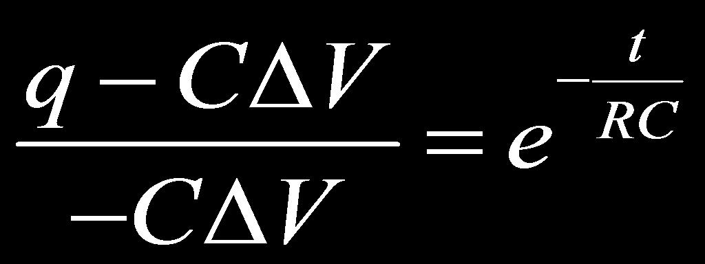
87 Discharging a Capacitor Kirchoff's Loop rule will be used to find the current and charge at any time after the switch is closed. because the charge on the capacitor is decreasing separating the variables The next step will be to integrate from t o to an arbitrary time t, where the charge decreases from q = Q to q.


88 Discharging a Capacitor Take the time derivative of the charge to find the current behavior.

89 Discharging a Capacitor The negative sign for the current indicates that the discharging current flows opposite to the charging current.
90 Discharging a Capacitor Plot the charge on the capacitor and the current through the circuit as a function of time.
91 19 What is the current through the 5 Ω resistor immediately after the switch is closed? A 0 A B 2 A C 4 A D 6 A E 8 A Answer
92 20 The circuit has been connected for a long time. The charge on the capacitor is: A 60 µc B 20 µc C 2 µc D 40 µc E 30 µc Answer
93 21 The circuit has been connected for a long time. What is the current through the 5 Ω resistor? A 8 A B 6 A C 4 A D 2 A E 0 A Answer
94 22 A capacitor is placed in series with a resistor and a battery. Which of the following graphs represents the charge on the capacitor as a function of time? A B C Answer D E
AP Physics C - E & M
 Slide 1 / 27 Slide 2 / 27 AP Physics C - E & M Current, Resistance & Electromotive Force 2015-12-05 www.njctl.org Slide 3 / 27 Electric Current Electric Current is defined as the movement of charge from
Electric Current & DC Circuits
 Electric Current & DC Circuits Circuits Click on the topic to go to that section Conductors Resistivity and Resistance Circuit Diagrams Measurement EMF & Terminal Voltage Kirchhoff's Rules Capacitors*
Electromotive Force. The electromotive force (emf), ε, of a battery is the maximum possible voltage that the battery can provide between its terminals
, ε, of a battery is the maximum possible voltage that the battery can provide between its terminals") Direct Current When the current in a circuit has a constant magnitude and direction, the current is called direct current Because the potential difference between the terminals of a battery is constant,
Direct Current When the current in a circuit has a constant magnitude and direction, the current is called direct current Because the potential difference between the terminals of a battery is constant,
 Superconductors A class of materials and compounds whose resistances fall to virtually zero below a certain temperature, T C T C is called the critical temperature The graph is the same as a normal metal
AP Physics C. Electric Circuits III.C
 AP Physics C Electric Circuits III.C III.C.1 Current, Resistance and Power The direction of conventional current Suppose the cross-sectional area of the conductor changes. If a conductor has no current,
Electric Current & DC Circuits How to Use this File Electric Current & DC Circuits Click on the topic to go to that section Circuits
 Slide 1 / 127 Slide 2 / 127 Electric Current & DC Circuits www.njctl.org Slide 3 / 127 How to Use this File Slide 4 / 127 Electric Current & DC Circuits Each topic is composed of brief direct instruction
Chapter 20 Electric Circuits
 Chapter 0 Electric Circuits Chevy olt --- Electric vehicle of the future Goals for Chapter 9 To understand the concept of current. To study resistance and Ohm s Law. To observe examples of electromotive
Chapter 3: Electric Current And Direct-Current Circuits
 Chapter 3: Electric Current And Direct-Current Circuits 3.1 Electric Conduction 3.1.1 Describe the microscopic model of current Mechanism of Electric Conduction in Metals Before applying electric field
Circuits. Electric Current & DC Circuits. Slide 1 / 127. Slide 2 / 127. Slide 3 / 127. Slide 4 / 127. Slide 5 / 127. Slide 6 / 127
 Slide 1 / 127 Slide 2 / 127 New Jersey Center for Teaching and Learning Electric Current & DC Circuits www.njctl.org Progressive Science Initiative This material is made freely available at www.njctl.org
Electric Currents. Resistors (Chapters 27-28)
") Electric Currents. Resistors (Chapters 27-28) Electric current I Resistance R and resistors Relation between current and resistance: Ohm s Law Resistivity ρ Energy dissipated by current. Electric power
Electric Currents. Resistors (Chapters 27-28) Electric current I Resistance R and resistors Relation between current and resistance: Ohm s Law Resistivity ρ Energy dissipated by current. Electric power
Chapter 26 Direct-Current and Circuits. - Resistors in Series and Parallel - Kirchhoff s Rules - Electric Measuring Instruments - R-C Circuits
 Chapter 26 Direct-Current and Circuits - esistors in Series and Parallel - Kirchhoff s ules - Electric Measuring Instruments - -C Circuits . esistors in Series and Parallel esistors in Series: V ax I V
Lecture Outline Chapter 21. Physics, 4 th Edition James S. Walker. Copyright 2010 Pearson Education, Inc.
 Lecture Outline Chapter 21 Physics, 4 th Edition James S. Walker Chapter 21 Electric Current and Direct- Current Circuits Units of Chapter 21 Electric Current Resistance and Ohm s Law Energy and Power
Electric Currents and Circuits
 Nicholas J. Giordano www.cengage.com/physics/giordano Chapter 19 Electric Currents and Circuits Marilyn Akins, PhD Broome Community College Electric Circuits The motion of charges leads to the idea of
Physics 142 Steady Currents Page 1. Steady Currents
 Physics 142 Steady Currents Page 1 Steady Currents If at first you don t succeed, try, try again. Then quit. No sense being a damn fool about it. W.C. Fields Electric current: the slow average drift of
Physics 115. General Physics II. Session 24 Circuits Series and parallel R Meters Kirchoff s Rules
 Physics 115 General Physics II Session 24 Circuits Series and parallel R Meters Kirchoff s Rules R. J. Wilkes Email: phy115a@u.washington.edu Home page: http://courses.washington.edu/phy115a/ 5/15/14 Phys
Electric Charge. Electric Charge ( q ) unbalanced charges positive and negative charges. n Units Coulombs (C)
 unbalanced charges positive and negative charges. n Units Coulombs (C)") Electric Charge Electric Charge ( q ) unbalanced charges positive and negative charges n Units Coulombs (C) Electric Charge How do objects become charged? Types of materials Conductors materials in which
Electric Charge Electric Charge ( q ) unbalanced charges positive and negative charges n Units Coulombs (C) Electric Charge How do objects become charged? Types of materials Conductors materials in which
Chapter 21 Electric Current and Direct- Current Circuits
 Chapter 21 Electric Current and Direct- Current Circuits 1 Overview of Chapter 21 Electric Current and Resistance Energy and Power in Electric Circuits Resistors in Series and Parallel Kirchhoff s Rules
AC vs. DC Circuits. Constant voltage circuits. The voltage from an outlet is alternating voltage
 Circuits AC vs. DC Circuits Constant voltage circuits Typically referred to as direct current or DC Computers, logic circuits, and battery operated devices are examples of DC circuits The voltage from
Chapter 28. Direct Current Circuits
 Chapter 28 Direct Current Circuits Circuit Analysis Simple electric circuits may contain batteries, resistors, and capacitors in various combinations. For some circuits, analysis may consist of combining
1 Written and composed by: Prof. Muhammad Ali Malik (M. Phil. Physics), Govt. Degree College, Naushera
, Govt. Degree College, Naushera") CURRENT ELECTRICITY Q # 1. What do you know about electric current? Ans. Electric Current The amount of electric charge that flows through a cross section of a conductor per unit time is known as electric
CURRENT ELECTRICITY Q # 1. What do you know about electric current? Ans. Electric Current The amount of electric charge that flows through a cross section of a conductor per unit time is known as electric
Physics 202: Lecture 5, Pg 1
 Resistance Resistors Series Parallel Ohm s law Electric Circuits Current Physics 132: Lecture e 15 Elements of Physics II Kirchhoff s laws Agenda for Today Physics 202: Lecture 5, Pg 1 Electric Current
Version 001 CIRCUITS holland (1290) 1
 1") Version CIRCUITS holland (9) This print-out should have questions Multiple-choice questions may continue on the next column or page find all choices before answering AP M 99 MC points The power dissipated
Version CIRCUITS holland (9) This print-out should have questions Multiple-choice questions may continue on the next column or page find all choices before answering AP M 99 MC points The power dissipated
Circuits. Circuits. Electric Current & DC Circuits. current and circuits presentation March 22, How to Use this File.
 New Jersey Center for Teaching and Learning Electric Current & DC Circuits Progressive Science Initiative This material is made freely available at www.njctl.org and is intended for the non commercial
Chapter 26 & 27. Electric Current and Direct- Current Circuits
 Chapter 26 & 27 Electric Current and Direct- Current Circuits Electric Current and Direct- Current Circuits Current and Motion of Charges Resistance and Ohm s Law Energy in Electric Circuits Combination
Class 8. Resistivity and Resistance Circuits. Physics 106. Winter Press CTRL-L to view as a slide show. Class 8. Physics 106.
 and Circuits and Winter 2018 Press CTRL-L to view as a slide show. Last time we learned about Capacitance Problems Parallel-Plate Capacitors Capacitors in Circuits Current Ohm s Law and Today we will learn
Electricity & Magnetism
 Electricity & Magnetism D.C. Circuits Marline Kurishingal Note : This chapter includes only D.C. In AS syllabus A.C is not included. Recap... Electrical Circuit Symbols : Draw and interpret circuit diagrams
Algebra Based Physics
 Page 1 of 105 Algebra Based Physics Electric Current & DC Circuits 2015-10-06 www.njctl.org Page 2 of 105 Electric Current & DC Circuits Circuits Conductors Resistivity and Resistance Circuit Diagrams
DC Circuits. Electromotive Force Resistor Circuits. Kirchoff s Rules. RC Circuits. Connections in parallel and series. Complex circuits made easy
 DC Circuits Electromotive Force esistor Circuits Connections in parallel and series Kirchoff s ules Complex circuits made easy C Circuits Charging and discharging Electromotive Force (EMF) EMF, E, is the
Chapter 16. Current and Drift Speed. Electric Current, cont. Current and Drift Speed, cont. Current and Drift Speed, final
 Chapter 6 Current, esistance, and Direct Current Circuits Electric Current Whenever electric charges of like signs move, an electric current is said to exist The current is the rate at which the charge
Chapter 3: Electric Current and Direct-Current Circuit
 Chapter 3: Electric Current and Direct-Current Circuit n this chapter, we are going to discuss both the microscopic aspect and macroscopic aspect of electric current. Direct-current is current that flows
physics for you February 11 Page 68
 urrent Electricity Passage 1 4. f the resistance of a 1 m length of a given wire t is observed that good conductors of heat are also is 8.13 10 3 W, and it carried a current 1, the good conductors of electricity.
PHYSICS. Chapter 27 Lecture FOR SCIENTISTS AND ENGINEERS A STRATEGIC APPROACH 4/E RANDALL D. KNIGHT
 PHYSICS FOR SCIENTISTS AND ENGINEERS A STRATEGIC APPROACH 4/E Chapter 27 Lecture RANDALL D. KNIGHT Chapter 27 Current and Resistance IN THIS CHAPTER, you will learn how and why charge moves through a wire
PHY102 Electricity Course Summary
 TOPIC 1 ELECTOSTTICS PHY1 Electricity Course Summary Coulomb s Law The magnitude of the force between two point charges is directly proportional to the product of the charges and inversely proportional
ELECTRIC CURRENTS D R M A R T A S T A S I A K D E P A R T M E N T O F C Y T O B I O L O G Y A N D P R O T E O M I C S
 ELECTRIC CURRENTS D R M A R T A S T A S I A K D E P A R T M E N T O F C Y T O B I O L O G Y A N D P R O T E O M I C S lecture based on 2016 Pearson Education, Ltd. The Electric Battery Electric Current
Review of Ohm's Law: The potential drop across a resistor is given by Ohm's Law: V= IR where I is the current and R is the resistance.
 DC Circuits Objectives The objectives of this lab are: 1) to construct an Ohmmeter (a device that measures resistance) using our knowledge of Ohm's Law. 2) to determine an unknown resistance using our
Physics 1214 Chapter 19: Current, Resistance, and Direct-Current Circuits
 Physics 1214 Chapter 19: Current, Resistance, and Direct-Current Circuits 1 Current current: (also called electric current) is an motion of charge from one region of a conductor to another. Current When
5. ELECTRIC CURRENTS
 5. ELECTRIC CURRENTS TOPIC OUTLINE Section Recommended Time Giancoli Section 5.1 Potential Difference, Current, Resistance 5.2 Electric Circuits 3h 19.1, 19.2 6.2 Electric Field and Force 6.3 Magnetic
Chapter 18 Electric Currents
 Chapter 18 Electric Currents 1 The Electric Battery Volta discovered that electricity could be created if dissimilar metals were connected by a conductive solution called an electrolyte. This is a simple
Capacitance. A different kind of capacitor: Work must be done to charge a capacitor. Capacitors in circuits. Capacitor connected to a battery
 Capacitance The ratio C = Q/V is a conductor s self capacitance Units of capacitance: Coulomb/Volt = Farad A capacitor is made of two conductors with equal but opposite charge Capacitance depends on shape
Physics 1302W.400 Lecture 21 Introductory Physics for Scientists and Engineering II
 Physics 1302W.400 Lecture 21 Introductory Physics for Scientists and Engineering II In today s lecture, we will learn to: Calculate the resistance of a conductor depending on the material and shape Apply
Resistivity and Temperature Coefficients (at 20 C)
") Homework # 4 Resistivity and Temperature Coefficients (at 0 C) Substance Resistivity, Temperature ( m) Coefficient, (C ) - Conductors Silver.59 x 0-0.006 Copper.6 x 0-0.006 Aluminum.65 x 0-0.0049 Tungsten
Homework # 4 Resistivity and Temperature Coefficients (at 0 C) Substance Resistivity, Temperature ( m) Coefficient, (C ) - Conductors Silver.59 x 0-0.006 Copper.6 x 0-0.006 Aluminum.65 x 0-0.0049 Tungsten
ELECTRIC CURRENT. Ions CHAPTER Electrons. ELECTRIC CURRENT and DIRECT-CURRENT CIRCUITS
 LCTRC CURRNT CHAPTR 25 LCTRC CURRNT and DRCTCURRNT CRCUTS Current as the motion of charges The Ampère Resistance and Ohm s Law Ohmic and nonohmic materials lectrical energy and power ons lectrons nside
Direct Current (DC) Circuits
 Circuits") Direct Current (DC) Circuits NOTE: There are short answer analysis questions in the Participation section the informal lab report. emember to include these answers in your lab notebook as they will be
Direct Current (DC) Circuits NOTE: There are short answer analysis questions in the Participation section the informal lab report. emember to include these answers in your lab notebook as they will be
Direct-Current Circuits. Physics 231 Lecture 6-1
 Direct-Current Circuits Physics 231 Lecture 6-1 esistors in Series and Parallel As with capacitors, resistors are often in series and parallel configurations in circuits Series Parallel The question then
Electric charge is conserved the arithmetic sum of the total charge cannot change in any interaction.
 Electrostatics Electric charge is conserved the arithmetic sum of the total charge cannot change in any interaction. Electric Charge in the Atom Atom: Nucleus (small, massive, positive charge) Electron
Flow Rate is the NET amount of water passing through a surface per unit time
 Electric Current An Analogy Water Flow in a Pipe H 2 0 gallons/minute Flow Rate is the NET amount of water passing through a surface per unit time Individual molecules are bouncing around with speeds of
Chapter 6 DIRECT CURRENT CIRCUITS. Recommended Problems: 6,9,11,13,14,15,16,19,20,21,24,25,26,28,29,30,31,33,37,68,71.
 Chapter 6 DRECT CURRENT CRCUTS Recommended Problems: 6,9,,3,4,5,6,9,0,,4,5,6,8,9,30,3,33,37,68,7. RESSTORS N SERES AND N PARALLEL - N SERES When two resistors are connected together as shown we said that
SIMPLE D.C. CIRCUITS AND MEASUREMENTS Background
 SIMPLE D.C. CICUITS AND MEASUEMENTSBackground This unit will discuss simple D.C. (direct current current in only one direction) circuits: The elements in them, the simple arrangements of these elements,
Chapter 28 Solutions
 Chapter 8 Solutions 8.1 (a) P ( V) R becomes 0.0 W (11.6 V) R so R 6.73 Ω (b) V IR so 11.6 V I (6.73 Ω) and I 1.7 A ε IR + Ir so 15.0 V 11.6 V + (1.7 A)r r 1.97 Ω Figure for Goal Solution Goal Solution
MEP 382: Design of Applied Measurement Systems Lecture 3: DC & AC Circuit Analysis
 Faculty of Engineering MEP 38: Design of Applied Measurement Systems Lecture 3: DC & AC Circuit Analysis Outline oltage and Current Ohm s Law Kirchoff s laws esistors Series and Parallel oltage Dividers
Read Chapter 7; pages:
 Forces Read Chapter 7; pages: 191-221 Objectives: - Describe how electrical charges exert forces on each other; Compare the strengths of electric and gravitational forces; Distinguish between conductors
Name: Class: Date: Multiple Choice Identify the letter of the choice that best completes the statement or answers the question.
 Name: Class: Date: AP REVIEW 4 Multiple Choice Identify the letter of the choice that best completes the statement or answers the question. 1. If a positively charged glass rod is used to charge a metal
physics 4/7/2016 Chapter 31 Lecture Chapter 31 Fundamentals of Circuits Chapter 31 Preview a strategic approach THIRD EDITION
 Chapter 31 Lecture physics FOR SCIENTISTS AND ENGINEERS a strategic approach THIRD EDITION randall d. knight Chapter 31 Fundamentals of Circuits Chapter Goal: To understand the fundamental physical principles
Chapter 7 Direct-Current Circuits
 Chapter 7 Direct-Current Circuits 7. Introduction... 7. Electromotive Force... 7.3 Resistors in Series and in Parallel... 4 7.4 Kirchhoff s Circuit Rules... 6 7.5 Voltage-Current Measurements... 8 7.6
Tactics Box 23.1 Using Kirchhoff's Loop Law
 PH203 Chapter 23 solutions Tactics Box 231 Using Kirchhoff's Loop Law Description: Knight/Jones/Field Tactics Box 231 Using Kirchhoff s loop law is illustrated Learning Goal: To practice Tactics Box 231
PH 222-2C Fall Circuits. Lectures Chapter 27 (Halliday/Resnick/Walker, Fundamentals of Physics 8 th edition)
") PH 222-2C Fall 2012 Circuits Lectures 11-12 Chapter 27 (Halliday/Resnick/Walker, Fundamentals of Physics 8 th edition) 1 Chapter 27 Circuits In this chapter we will cover the following topics: -Electromotive
PH 222-2C Fall 2012 Circuits Lectures 11-12 Chapter 27 (Halliday/Resnick/Walker, Fundamentals of Physics 8 th edition) 1 Chapter 27 Circuits In this chapter we will cover the following topics: -Electromotive
Physics 42 Exam 2 PRACTICE Name: Lab
 Physics 42 Exam 2 PRACTICE Name: Lab 1 2 3 4 Conceptual Multiple Choice (2 points each) Circle the best answer. 1.Rank in order, from brightest to dimmest, the identical bulbs A to D. A. C = D > B > A
52 VOLTAGE, CURRENT, RESISTANCE, AND POWER
 52 VOLTAGE, CURRENT, RESISTANCE, AND POWER 1. What is voltage, and what are its units? 2. What are some other possible terms for voltage? 3. Batteries create a potential difference. The potential/voltage
Physics 2401 Summer 2, 2008 Exam II
 Physics 2401 Summer 2, 2008 Exam II e = 1.60x10⁻¹⁹ C, m(electron) = 9.11x10⁻³¹ kg, ε 0 = 8.845x10⁻¹² C 2 /Nm 2, k e = 9.0x10 9 Nm 2 /C 2, m(proton) = 1.67x10⁻²⁷ kg. n = nano = 10-9, µ = micro = 10-6, m
Can You Light the Bulb?
 AP PHYSCS 2 Can You Light the Bulb? UNT 4 DC circuits and RC circuits. CHAPTER 16 DC CRCUTS 1. Draw wires and make the bulb light. 2. Modify your drawing and use ONE wire only! Complete circuits To check
Direct Current Circuits. February 18, 2014 Physics for Scientists & Engineers 2, Chapter 26 1
 Direct Current Circuits February 18, 2014 Physics for Scientists & Engineers 2, Chapter 26 1 Kirchhoff s Junction Rule! The sum of the currents entering a junction must equal the sum of the currents leaving
Section 1 Electric Charge and Force
 CHAPTER OUTLINE Section 1 Electric Charge and Force Key Idea questions > What are the different kinds of electric charge? > How do materials become charged when rubbed together? > What force is responsible
the electrical nature of matter is inherent in its atomic structure E & M atoms are made up of p+, n, and e- the nucleus has p+ and n
 Electric Forces and Fields E & M the electrical nature of matter is inherent in its atomic structure atoms are made up of p+, n, and e- a.k.a Electricity and Magnetism the nucleus has p+ and n surrounding
10/14/2018. Current. Current. QuickCheck 30.3
 Current If QCurrent is the total amount of charge that has moved past a point in a wire, we define the current I in the wire to be the rate of charge flow: The SI unit for current is the coulomb per second,
Science Olympiad Circuit Lab
 Science Olympiad Circuit Lab Key Concepts Circuit Lab Overview Circuit Elements & Tools Basic Relationships (I, V, R, P) Resistor Network Configurations (Series & Parallel) Kirchhoff s Laws Examples Glossary
A Review of Circuitry
 1 A Review of Circuitry There is an attractive force between a positive and a negative charge. In order to separate these charges, a force at least equal to the attractive force must be applied to one
Outline of College Physics OpenStax Book
 Outline of College Physics OpenStax Book Taken from the online version of the book Dec. 27, 2017 18. Electric Charge and Electric Field 18.1. Static Electricity and Charge: Conservation of Charge Define
Physics 169. Luis anchordoqui. Kitt Peak National Observatory. Wednesday, March 8, 17
 Physics 169 Kitt Peak National Observatory Luis anchordoqui 1 5.1 Ohm s Law and Resistance ELECTRIC CURRENT is defined as flow of electric charge through a cross-sectional area Convention i = dq dt Unit
R R V I R. Conventional Current. Ohms Law V = IR
 DC Circuits opics EMF and erminal oltage esistors in Series and in Parallel Kirchhoff s ules EMFs in Series and in Parallel Capacitors in Series and in Parallel Ammeters and oltmeters Conventional Current
Ch 28-DC Circuits! 1.) EMF & Terminal Voltage! 9.0 V 8.7 V 8.7 V. V =! " Ir. Terminal Open circuit internal! voltage voltage (emf) resistance" 2.
 EMF & Terminal Voltage! 9.0 V 8.7 V 8.7 V. V =! Ir. Terminal Open circuit internal! voltage voltage (emf) resistance 2.") Ch 28-DC Circuits! 1.) EMF & Terminal Voltage! 9.0 V 8.7 V 8.7 V V =! " Ir Terminal Open circuit internal! voltage voltage (emf) resistance" 2.) Resistors in series! One of the bits of nastiness about
Ch 28-DC Circuits! 1.) EMF & Terminal Voltage! 9.0 V 8.7 V 8.7 V V =! " Ir Terminal Open circuit internal! voltage voltage (emf) resistance" 2.) Resistors in series! One of the bits of nastiness about
Louisiana State University Physics 2102, Exam 2, March 5th, 2009.
 PRINT Your Name: Instructor: Louisiana State University Physics 2102, Exam 2, March 5th, 2009. Please be sure to PRINT your name and class instructor above. The test consists of 4 questions (multiple choice),
Chapter 19 Lecture Notes
 Chapter 19 Lecture Notes Physics 2424 - Strauss Formulas: R S = R 1 + R 2 +... C P = C 1 + C 2 +... 1/R P = 1/R 1 + 1/R 2 +... 1/C S = 1/C 1 + 1/C 2 +... q = q 0 [1-e -t/(rc) ] q = q 0 e -t/(rc τ = RC
Chapter 17. Current and Resistance. Sections: 1, 3, 4, 6, 7, 9
 Chapter 17 Current and Resistance Sections: 1, 3, 4, 6, 7, 9 Equations: 2 2 1 e r q q F = k 2 e o r Q k q F E = = I R V = A L R ρ = )] ( 1 [ o o T T + = α ρ ρ V I V t Q P = = R V R I P 2 2 ) ( = = C Q
Energy. E d. Energy Power = time. E t P = E t = P
 Energy Forms of energy Energy can never be created or destroyed. It can only be transformed from one type to another (or other types). here are many different forms of energy: Kinetic (movement) Energy
Physics 7B-1 (A/B) Professor Cebra. Winter 2010 Lecture 2. Simple Circuits. Slide 1 of 20
 Professor Cebra. Winter 2010 Lecture 2. Simple Circuits. Slide 1 of 20") Physics 7B-1 (A/B) Professor Cebra Winter 2010 Lecture 2 Simple Circuits Slide 1 of 20 Conservation of Energy Density In the First lecture, we started with energy conservation. We divided by volume (making
Physics 7B-1 (A/B) Professor Cebra Winter 2010 Lecture 2 Simple Circuits Slide 1 of 20 Conservation of Energy Density In the First lecture, we started with energy conservation. We divided by volume (making
What happens when things change. Transient current and voltage relationships in a simple resistive circuit.
 Module 4 AC Theory What happens when things change. What you'll learn in Module 4. 4.1 Resistors in DC Circuits Transient events in DC circuits. The difference between Ideal and Practical circuits Transient
Mansfield Independent School District AP Physics C: Electricity and Magnetism Year at a Glance
 Mansfield Independent School District AP Physics C: Electricity and Magnetism Year at a Glance First Six-Weeks Second Six-Weeks Third Six-Weeks Lab safety Lab practices and ethical practices Math and Calculus
Chapter 21 Electric Current and Direct- Current Circuits
 Chapter 21 Electric Current and Direct- Current Circuits Units of Chapter 21 Electric Current Resistance and Ohm s Law Energy and Power in Electric Circuits Resistors in Series and Parallel Kirchhoff s
Chapter 19. Electric Current, Resistance, and DC Circuit Analysis
 Chapter 19 Electric Current, Resistance, and DC Circuit Analysis I = dq/dt Current is charge per time SI Units: Coulombs/Second = Amps Direction of Electron Flow _ + Direction of Conventional Current:
Circuits. Electric Current & DC Circuits Circuits. Unit 6. April Electric Current. Electric Current. Electric Current. ΔQ Δt
 Electric Current & DC Circuits Electric Current & DC Circuits Circuits Conductors esistivity and esistance Click on the topic to go to that section Circuit Diagrams Measurement Electric Current Circuits
PhysicsAndMathsTutor.com
 Electricity May 02 1. The graphs show the variation with potential difference V of the current I for three circuit elements. PhysicsAndMathsTutor.com When the four lamps are connected as shown in diagram
Chapter 26 Direct-Current Circuits
 Chapter 26 Direct-Current Circuits 1 Resistors in Series and Parallel In this chapter we introduce the reduction of resistor networks into an equivalent resistor R eq. We also develop a method for analyzing
Chapter 25. Electromotive Force. PowerPoint Lectures for University Physics, Twelfth Edition Hugh D. Young and Roger A. Freedman
 Chapter 25 Current, Resistance, and Electromotive Force PowerPoint Lectures for University Physics, Twelfth Edition Hugh D. Young and Roger A. Freedman Lectures by James Pazun Main points (I, R, emf) 1.
Electric Current. Chapter 17. Electric Current, cont QUICK QUIZ Current and Resistance. Sections: 1, 3, 4, 6, 7, 9
 Electric Current Chapter 17 Current and Resistance Sections: 1, 3, 4, 6, 7, 9 Whenever electric charges of like signs move, an electric current is said to exist The current is the rate at which the charge
Circuits. PHY2054: Chapter 18 1
 Circuits PHY2054: Chapter 18 1 What You Already Know Microscopic nature of current Drift speed and current Ohm s law Resistivity Calculating resistance from resistivity Power in electric circuits PHY2054:
Chapter 2. Engr228 Circuit Analysis. Dr Curtis Nelson
 Chapter 2 Engr228 Circuit Analysis Dr Curtis Nelson Chapter 2 Objectives Understand symbols and behavior of the following circuit elements: Independent voltage and current sources; Dependent voltage and
M. C. Escher: Waterfall. 18/9/2015 [tsl425 1/29]
![M. C. Escher: Waterfall. 18/9/2015 [tsl425 1/29]](/thumbs/76/73138710.jpg "M. C. Escher: Waterfall. 18/9/2015 [tsl425 1/29]") M. C. Escher: Waterfall 18/9/2015 [tsl425 1/29] Direct Current Circuit Consider a wire with resistance R = ρl/a connected to a battery. Resistor rule: In the direction of I across a resistor with resistance
M. C. Escher: Waterfall 18/9/2015 [tsl425 1/29] Direct Current Circuit Consider a wire with resistance R = ρl/a connected to a battery. Resistor rule: In the direction of I across a resistor with resistance
AP Physics C Mechanics Objectives
 AP Physics C Mechanics Objectives I. KINEMATICS A. Motion in One Dimension 1. The relationships among position, velocity and acceleration a. Given a graph of position vs. time, identify or sketch a graph
Physics 212 Midterm 2 Form A
 1. A wire contains a steady current of 2 A. The charge that passes a cross section in 2 s is: A. 3.2 10-19 C B. 6.4 10-19 C C. 1 C D. 2 C E. 4 C 2. In a Physics 212 lab, Jane measures the current versus
LABORATORY 4 ELECTRIC CIRCUITS I. Objectives
 LABORATORY 4 ELECTRIC CIRCUITS I Objectives to be able to discuss potential difference and current in a circuit in terms of electric field, work per unit charge and motion of charges to understand that
CLASS XII WB SET A PHYSICS
 PHYSICS 1. Two cylindrical straight and very long non magnetic conductors A and B, insulated from each other, carry a current I in the positive and the negative z-direction respectively. The direction
Circuits Capacitance of a parallel-plate capacitor : C = κ ε o A / d. (ρ = resistivity, L = length, A = cross-sectional area) Resistance : R = ρ L / A
 Resistance : R = ρ L / A") k = 9.0 x 10⁹ N m2 / C2 e = 1.60 x 10⁻¹⁹ C ε o = 8.85 x 10⁻¹² C2 / N m2 Coulomb s law: F = k q Q / r2 (unlike charges attract, like charges repel) Electric field from a point charge : E = k q / r2 ( towards
k = 9.0 x 10⁹ N m2 / C2 e = 1.60 x 10⁻¹⁹ C ε o = 8.85 x 10⁻¹² C2 / N m2 Coulomb s law: F = k q Q / r2 (unlike charges attract, like charges repel) Electric field from a point charge : E = k q / r2 ( towards
Electromagnetism Checklist
 Electromagnetism Checklist Elementary Charge and Conservation of Charge 4.1.1A Convert from elementary charge to charge in coulombs What is the charge in coulombs on an object with an elementary charge
Chapter 27. Circuits
 Chapter 27 Circuits 1 1. Pumping Chagres We need to establish a potential difference between the ends of a device to make charge carriers follow through the device. To generate a steady flow of charges,
AP Physics C. Magnetism - Term 4
 AP Physics C Magnetism - Term 4 Interest Packet Term Introduction: AP Physics has been specifically designed to build on physics knowledge previously acquired for a more in depth understanding of the world
PHYSICS ASSIGNMENT ES/CE/MAG. Class XII
 PHYSICS ASSIGNMENT ES/CE/MAG Class XII MM : 70 1. What is dielectric strength of a medium? Give its value for vacuum. 1 2. What is the physical importance of the line integral of an electrostatic field?
Chapters 24/25: Current, Circuits & Ohm s law Thursday September 29 th **Register your iclickers**
 Chapters 24/25: Current, Circuits & Ohm s law Thursday September 29 th **Register your iclickers** Conductors under dynamic conditions Current, current density, drift velocity Ohm s law Types of conductor
Chapter 24: Electric Current
 Chapter 24: Electric Current Current Definition of current A current is any motion of charge from one region to another. Suppose a group of charges move perpendicular to surface of area A. The current
Chapter 25 Current, Resistance, and Electromotive Force
 Chapter 25 Current, Resistance, and Electromotive Force Lecture by Dr. Hebin Li Goals for Chapter 25 To understand current and how charges move in a conductor To understand resistivity and conductivity
COPYRIGHTED MATERIAL. DC Review and Pre-Test. Current Flow CHAPTER
 Kybett c0.tex V3-03/3/2008 8:44pm Page CHAPTER DC Review and Pre-Test Electronics cannot be studied without first understanding the basics of electricity. This chapter is a review and pre-test on those