physics 4/7/2016 Chapter 31 Lecture Chapter 31 Fundamentals of Circuits Chapter 31 Preview a strategic approach THIRD EDITION
|
|
|
- Eugenia Watson
- 6 years ago
- Views:
Transcription


1 Chapter 31 Lecture physics FOR SCIENTISTS AND ENGINEERS a strategic approach THIRD EDITION randall d. knight Chapter 31 Fundamentals of Circuits Chapter Goal: To understand the fundamental physical principles that govern electric circuits. Slide 31-2 Chapter 31 Preview Slide


2 Chapter 31 Preview Slide 31-4 Chapter 31 Preview Slide 31-5 Chapter 31 Preview Slide


3 Chapter 31 Preview Slide 31-7 Chapter 31 Preview Slide 31-8 Chapter 31 Reading Quiz Slide
4 Reading Question 31.1 How many laws are named after Kirchhoff? A. 0. B. 1. C. 2. D. 3. E. 4. Slide Reading Question 31.1 How many laws are named after Kirchhoff? A. 0. B. 1. C. 2. D. 3. E. 4. Slide Reading Question 31.2 What property of a real battery makes its potential difference slightly different than that of an ideal battery? A. Short circuit. B. Chemical potential. C. Internal resistance. D. Effective capacitance. E. Inductive constant. Slide
5 Reading Question 31.2 What property of a real battery makes its potential difference slightly different than that of an ideal battery? A. Short circuit. B. Chemical potential. C. Internal resistance. D. Effective capacitance. E. Inductive constant. Slide Reading Question 31.3 In an RC circuit, what is the name of the quantity represented by the symbol τ? A. Period. B. Torque. C. Terminal voltage. D. Time constant. E. Coefficient of thermal expansion. Slide Reading Question 31.3 In an RC circuit, what is the name of the quantity represented by the symbol τ? A. Period. B. Torque. C. Terminal voltage. D. Time constant. E. Coefficient of thermal expansion. Slide
6 Reading Question 31.4 Which of the following are ohmic materials: A. Batteries. B. Wires. C. Resistors. D. Materials a and b. E. Materials b and c. Slide Reading Question 31.4 Which of the following are ohmic materials: A. Batteries. B. Wires. C. Resistors. D. Materials a and b. E. Materials b and c. Slide Reading Question 31.5 The equivalent resistance for a group of parallel resistors is A. Less than any resistor in the group. B. Equal to the smallest resistance in the group. C. Equal to the average resistance of the group. D. Equal to the largest resistance in the group. E. Larger than any resistor in the group. Slide

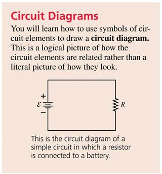
7 Reading Question 31.5 The equivalent resistance for a group of parallel resistors is A. Less than any resistor in the group. B. Equal to the smallest resistance in the group. C. Equal to the average resistance of the group. D. Equal to the largest resistance in the group. E. Larger than any resistor in the group. Slide Chapter 31 Content, Examples, and QuickCheck Questions Slide Circuit Diagrams The top figure shows a literal picture of a resistor and a capacitor connected by wires to a battery. The bottom figure is a circuit diagram of the same circuit. A circuit diagram is a logical picture of what is connected to what. Slide


8 Circuit Elements Slide Circuit Diagrams A circuit diagram replaces pictures of the circuit elements with symbols. The longer line at one end of the battery symbol represents the positive terminal of the battery. The battery s emf is shown beside the battery. + and symbols, even though somewhat redundant, are shown beside the terminals. Slide QuickCheck 31.1 Does the bulb light? A. Yes. B. No. C. I m not sure. Slide

9 QuickCheck 31.1 Does the bulb light? A. Yes. B. No. Not a complete circuit C. I m not sure. Slide QuickCheck 31.2 The three bulbs are identical and the two batteries are identical. Compare the brightnesses of the bulbs. A. A > B > C. B. A > C > B. C. A > B = C. D. A < B = C. E. A = B = C. Slide QuickCheck 31.2 The three bulbs are identical and the two batteries are identical. Compare the brightnesses of the bulbs. A. A > B > C. B. A > C > B. C. A > B = C. D. A < B = C. E. A = B = C. This question is checking your initial intuition. We ll return to it later. Slide
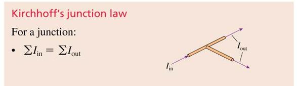
10 QuickCheck 31.3 The three bulbs are identical and the two batteries are identical. Compare the brightnesses of the bulbs. A. A > B > C. B. A > C > B. C. A > B = C. D. A < B = C. E. A = B = C. Slide QuickCheck 31.3 The three bulbs are identical and the two batteries are identical. Compare the brightnesses of the bulbs. A. A > B > C. B. A > C > B. C. A > B = C. D. A < B = C. E. A = B = C. This question is checking your initial intuition. We ll return to it later. Slide Kirchhoff s Junction Law For a junction, the law of conservation of current requires that: where the Σ symbol means summation. This basic conservation statement is called Kirchhoff s junction law. Slide


11 Kirchhoff s Loop Law For any path that starts and ends at the same point: The sum of all the potential differences encountered while moving around a loop or closed path is zero. This statement is known as Kirchhoff s loop law. Slide Tactics: Using Kirchhoff s Loop Law Slide Tactics: Using Kirchhoff s Loop Law Slide
12 QuickCheck 31.4 The current through the 3 Ω resistor is A. 9 A. B. 6 A. C. 5 A. D. 3 A. E. 1 A. Slide QuickCheck 31.4 The current through the 3 Ω resistor is A. 9 A. B. 6 A. C. 5 A. D. 3 A. E. 1 A. Slide The Basic Circuit The most basic electric circuit is a single resistor connected to the two terminals of a battery. Figure (a) shows a literal picture of the circuit elements and the connecting wires. Figure (b) is the circuit diagram. This is a complete circuit, forming a continuous path between the battery terminals. Slide

13 Analyzing the Basic Circuit Slide Lightbulb Puzzle #1 The figure shows two identical lightbulbs in a circuit. The current through both bulbs is exactly the same! It s not the current that the bulbs use up, it s energy. The battery creates a potential difference, which supplies potential energy to the charges. As the charges move through the lightbulbs, they lose some of their potential energy, transferring the energy to the bulbs. Slide QuickCheck 31.5 The potential difference across the 10 resistor is A. 30 V. B. 20 V. C. 15 V. D. 10 V. E. 5 V. Slide
14 QuickCheck 31.5 The potential difference across the 10 resistor is A. 30 V. B. 20 V. C. 15 V. D. 10 V. E. 5 V. Slide QuickCheck 31.6 What things about the resistors in this circuit are the same for all three? A. Current I. B. Potential difference V. C. Resistance R. D. A and B. E. B and C. Slide QuickCheck 31.6 What things about the resistors in this circuit are the same for all three? A. Current I. B. Potential difference V. C. Resistance R. D. A and B. E. B and C. Slide


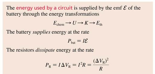
15 Energy and Power The power supplied by a battery is: The units of power are J/s or W. The power dissipated by a resistor is: Or, in terms of the potential drop across the resistor: Slide Example 31.2 Delivering Power Slide Power Dissipation in a Resistor A current-carrying resistor dissipates power because the electric force does work on the charges. Slide
16 QuickCheck 31.7 Which resistor dissipates more power? A. The 9 Ω resistor. B. The 1 Ω resistor. C. They dissipate the same power. Slide QuickCheck 31.7 Which resistor dissipates more power? A. The 9 Ω resistor. B. The 1 Ω resistor. C. They dissipate the same power. Slide QuickCheck 31.8 Which has a larger resistance, a 60 W lightbulb or a 100 W lightbulb? A. The 60 W bulb. B. The 100 W bulb. C. Their resistances are the same. D. There s not enough information to tell. Slide


17 QuickCheck 31.8 Which has a larger resistance, a 60 W lightbulb or a 100 W lightbulb? A. The 60 W bulb. B. The 100 W bulb. C. Their resistances are the same. D. There s not enough information to tell. Slide Example 31.3 The Power of Light Slide Example 31.3 The Power of Light Slide

18 QuickCheck 31.9 Which bulb is brighter? A. The 60 W bulb. B. The 100 W bulb. C. Their brightnesses are the same. D. There s not enough information to tell. Slide QuickCheck 31.9 Which bulb is brighter? A. The 60 W bulb. B. The 100 W bulb. C. Their brightnesses are the same. D. There s not enough information to tell. P = I 2 R and both have the same current. Slide Example 31.4 The Power of Sound Slide

19 Kilowatt Hours The product of watts and seconds is joules, the SI unit of energy. However, most electric companies prefers to use the kilowatt hour, to measure the energy you use each month. Examples: A 4000 W electric water heater uses 40 kwh of energy in 10 hours. A 1500 W hair dryer uses 0.25 kwh of energy in 10 minutes. The average cost of electricity in the United States is 10 per kwh ($0.10/kWh). Slide Lightbulb Puzzle #2 The figure shows three identical lightbulbs in two different circuits. The voltage drop across A is the same as the total voltage drop across both B and C. More current will pass through Bulb A, and it will be brighter than either B or C. Slide Series Resistors The figure below shows two resisters connected in series between points a and b. The total potential difference between points a and b is the sum of the individual potential differences across R 1 and R 2 : Slide
20 Series Resistors Suppose we replace R 1 and R 2 with a single resistor with the same current I and the same potential difference V ab. Ohm s law gives resistance between points a and b: Slide Series Resistors Resistors that are aligned end to end, with no junctions between them, are called series resistors or, sometimes, resistors in series. The current I is the same through all resistors placed in series. If we have N resistors in series, their equivalent resistance is: The behavior of the circuit will be unchanged if the N series resistors are replaced by the single resistor R eq. Slide QuickCheck The battery current I is A. 3 A. B. 2 A. C. 1 A. D. 2/3 A. E. 1/2 A. Slide

21 QuickCheck The battery current I is A. 3 A. B. 2 A. C. 1 A. D. 2/3 A. E. 1/2 A. Slide Example 31.5 A Series Resistor Circuit Slide Example 31.5 A Series Resistor Circuit Slide

22 Example 31.5 A Series Resistor Circuit Slide Example 31.5 A Series Resistor Circuit Slide Ammeters Figure (a) shows a simple one-resistor circuit. We can measure the current by breaking the connection and inserting an ammeter in series. The resistance of the ammeter is negligible. The potential difference across the resistor must be V R = IR = 3.0 V. So the battery s emf must be 3.0 V. Slide


23 Real Batteries Real batteries have what is called an internal resistance, which is symbolized by r. Slide Real Batteries A single resistor connected to a real battery is in series with the battery s internal resistance, giving R eq = R + r. Slide Example 31.6 Lighting Up a Flashlight Slide

")

24 Example 31.6 Lighting Up a Flashlight Slide A Short Circuit The figure shows an ideal wire shorting out a battery. If the battery were ideal, shorting it with an ideal wire (R = 0 Ω) would cause the current to be infinite! In reality, the battery s internal resistance r becomes the only resistance in the circuit. The short-circuit current is: Slide Example 31.7 A Short-Circuited Battery Slide
25 Lightbulb Puzzle #3 The figure shows three identical lightbulbs in a circuit. When the switch is closed, an alternate pathway for the current to get from bulb A back to the battery is created. This decreases the overall resistance of the circuit, and the brightess of bulb A increases. Slide Parallel Resistors The figure below shows two resisters connected in parallel between points c and d. By Kirchhoff s junction law, the input current is the sum of the current through each resistor: I = I 1 + I 2. Slide Series Resistors Suppose we replace R 1 and R 2 with a single resistor with the same current I and the same potential difference V cd. Ohm s law gives resistance between points c and d: Slide
26 Parallel Resistors Resistors connected at both ends are called parallel resistors or, sometimes, resistors in parallel. The left ends of all the resistors connected in parallel are held at the same potential V 1, and the right ends are all held at the same potential V 2. The potential differences V are the same across all resistors placed in parallel. If we have N resistors in parallel, their equivalent resistance is: The behavior of the circuit will be unchanged if the N parallel resistors are replaced by the single resistor R eq. Slide QuickCheck The battery current I is A. 3 A. B. 2 A. C. 1 A. D. 2/3 A. E. 1/2 A. Slide QuickCheck The battery current I is A. 3 A. B. 2 A. C. 1 A. D. 2/3 A. E. 1/2 A. Slide

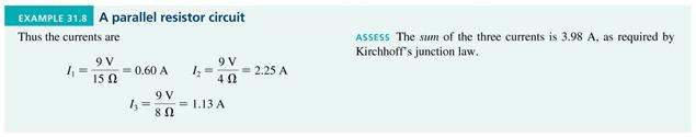
27 Example 31.8 A Parallel Resistor Circuit Slide Example 31.8 A Parallel Resistor Circuit Slide Example 31.8 A Parallel Resistor Circuit Slide
28 QuickCheck When the switch closes, the battery current A. Increases. B. Stays the same. C. Decreases. Slide QuickCheck When the switch closes, the battery current A. Increases. B. Stays the same. C. Decreases. Equivalent resistance decreases. Potential difference is unchanged. Slide QuickCheck The three bulbs are identical and the two batteries are identical. Compare the brightnesses of the bulbs. A. A > B > C. B. A > C > B. C. A > B = C. D. A < B = C. E. A = B = C. Slide
29 QuickCheck The three bulbs are identical and the two batteries are identical. Compare the brightnesses of the bulbs. A. A > B > C. B. A > C > B. C. A > B = C. D. A < B = C. E. A = B = C. Slide QuickCheck The three bulbs are identical and the two batteries are identical. Compare the brightnesses of the bulbs. A. A > B > C. B. A > C > B. C. A > B = C. D. A < B = C. E. A = B = C. Slide QuickCheck The three bulbs are identical and the two batteries are identical. Compare the brightnesses of the bulbs. A. A > B > C. B. A > C > B. C. A > B = C. D. A < B = C. E. A = B = C. Slide

30 QuickCheck The lightbulbs are identical. Initially both bulbs are glowing. What happens when the switch is closed? A. Nothing. B. A stays the same; B gets dimmer. C. A gets brighter; B stays the same. D. Both get dimmer. E. A gets brighter; B goes out. Slide QuickCheck The lightbulbs are identical. Initially both bulbs are glowing. What happens when the switch is closed? A. Nothing. B. A stays the same; B gets dimmer. C. A gets brighter; B stays the same. D. Both get dimmer. E. A gets brighter; B goes out. Short circuit. Zero resistance path. Slide Voltmeters Figure (a) shows a simple circuit with a resistor and a real battery. We can measure the potential difference across the resistor by connecting a voltmeter in parallel across the resistor. The resistance of the voltmeter must be very high. The internal resistance is: Slide
31 QuickCheck What does the voltmeter read? A. 6 V. B. 3 V. C. 2 V. D. Some other value. E. Nothing because this will fry the meter. Slide QuickCheck What does the voltmeter read? A. 6 V. B. 3 V. C. 2 V. D. Some other value. E. Nothing because this will fry the meter. Slide QuickCheck What does the ammeter read? A. 6 A. B. 3 A. C. 2 A. D. Some other value. E. Nothing because this will fry the meter. Slide


32 QuickCheck What does the ammeter read? A. 6 A. B. 3 A. C. 2 A. D. Some other value. E. Nothing because this will fry the meter. Slide Problem-Solving Strategy: Resistor Circuits Slide Problem-Solving Strategy: Resistor Circuits Slide


33 Getting Grounded The earth itself is a conductor. If we connect one point of a circuit to the earth by an ideal wire, we can agree to call potential of this point to be that of the earth: V earth = 0 V. The wire connecting the circuit to the earth is not part of a complete circuit, so there is no current in this wire! A circuit connected to the earth in this way is said to be grounded, and the wire is called the ground wire. The circular prong of a three-prong plug is a connection to ground. Slide A Circuit That Is Grounded The figure shows a circuit with a 10 V battery and two resistors in series. The symbol beneath the circuit is the ground symbol. The potential at the ground is V = 0. Grounding the circuit allows us to have specific values for potential at each point in the circuit, rather than just potential differences. Slide Example A Grounded Circuit Slide

34 Example A Grounded Circuit Slide Example A Grounded Circuit Slide Example A Grounded Circuit Slide
35 Example A Grounded Circuit Slide RC Circuits The figure shows a charged capacitor, a switch, and a resistor. At t = 0, the switch closes and the capacitor begins to discharge through the resistor. A circuit such as this, with resistors and capacitors, is called an RC circuit. We wish to determine how the current through the resistor will vary as a function of time after the switch is closed. Slide RC Circuits The figure shows an RC circuit, some time after the switch was closed. Kirchhoff s loop law applied to this circuit clockwise is: Q and I in this equation are the instantaneous values of the capacitor charge and the resistor current. The resistor current is the rate at which charge is removed from the capacitor: Slide
36 RC Circuits Knowing that I = dq/dt, the loop law for a simple closed RC circuit is: Rearranging and integrating: where the time constant τ is: Slide RC Circuits Slide QuickCheck Which capacitor discharges more quickly after the switch is closed? A. Capacitor A. B. Capacitor B. C. They discharge at the same rate. D. Can t say without knowing the initial amount of charge. Slide
37 QuickCheck Which capacitor discharges more quickly after the switch is closed? Smaller time constantτ = RC A. Capacitor A. B. Capacitor B. C. They discharge at the same rate. D. Can t say without knowing the initial amount of charge. Slide RC Circuits The charge on the capacitor of an RC circuit is: where Q 0 is the charge at t = 0, and τ = RC is the time constant. The capacitor voltage is directly proportional to the charge, so: Where V 0 is the voltage at t = 0. The current also can be found to decay exponentially: Slide RC Circuits Slide
38 QuickCheck The capacitor is initially unchanged. Immediately after the switch closes, the capacitor voltage is A. 0 V. B. Somewhere between 0 V and 6 V. C. 6 V. D. Undefined. Slide QuickCheck The capacitor is initially unchanged. Immediately after the switch closes, the capacitor voltage is A. 0 V. B. Somewhere between 0 V and 6 V. C. 6 V. D. Undefined. Slide Charging a Capacitor Figure (a) shows a circuit that charges a capacitor. The capacitor charge at time t is: where τ = RC. This upside-down decay is shown in figure (b). Slide
39 QuickCheck The red curve shows how the capacitor charges after the switch is closed at t = 0. Which curve shows the capacitor charging if the value of the resistor is reduced? Slide QuickCheck The red curve shows how the capacitor charges after the switch is closed at t = 0. Which curve shows the capacitor charging if the value of the resistor is reduced? Smaller time constant. Same ultimate amount of charge. Slide Chapter 31 Summary Slides Slide


40 General Strategy Slide General Strategy Slide General Strategy Slide


41 Important Concepts Slide Important Concepts Slide Important Concepts Slide
Agenda for Today. Elements of Physics II. Resistance Resistors Series Parallel Ohm s law Electric Circuits. Current Kirchoff s laws
 Resistance Resistors Series Parallel Ohm s law Electric Circuits Physics 132: Lecture e 17 Elements of Physics II Current Kirchoff s laws Agenda for Today Physics 201: Lecture 1, Pg 1 Clicker Question
Clicker Session Currents, DC Circuits
 Clicker Session Currents, DC Circuits Wires A wire of resistance R is stretched uniformly (keeping its volume constant) until it is twice its original length. What happens to the resistance? 1) it decreases
Chapter 21 Electric Current and Direct- Current Circuits
 Chapter 21 Electric Current and Direct- Current Circuits Units of Chapter 21 Electric Current Resistance and Ohm s Law Energy and Power in Electric Circuits Resistors in Series and Parallel Kirchhoff s
10/14/2018. Current. Current. QuickCheck 30.3
 Current If QCurrent is the total amount of charge that has moved past a point in a wire, we define the current I in the wire to be the rate of charge flow: The SI unit for current is the coulomb per second,
Lecture Outline Chapter 21. Physics, 4 th Edition James S. Walker. Copyright 2010 Pearson Education, Inc.
 Lecture Outline Chapter 21 Physics, 4 th Edition James S. Walker Chapter 21 Electric Current and Direct- Current Circuits Units of Chapter 21 Electric Current Resistance and Ohm s Law Energy and Power
Parallel Resistors (32.6)
") Parallel Resistors (32.6) Resistors connected at both ends are called parallel resistors The important thing to note is that: the two left ends of the resistors are at the same potential. Also, the two
Parallel Resistors (32.6) Resistors connected at both ends are called parallel resistors The important thing to note is that: the two left ends of the resistors are at the same potential. Also, the two
Parallel Resistors (32.6)
") Parallel Resistors (32.6) Resistors connected at both ends are called parallel resistors Neil Alberding (SFU Physics) Physics 121: Optics, Electricity & Magnetism Spring 2010 1 / 1 Parallel Resistors (32.6)
Parallel Resistors (32.6) Resistors connected at both ends are called parallel resistors Neil Alberding (SFU Physics) Physics 121: Optics, Electricity & Magnetism Spring 2010 1 / 1 Parallel Resistors (32.6)
Chapter 19. Electric Current, Resistance, and DC Circuit Analysis
 Chapter 19 Electric Current, Resistance, and DC Circuit Analysis I = dq/dt Current is charge per time SI Units: Coulombs/Second = Amps Direction of Electron Flow _ + Direction of Conventional Current:
Tactics Box 23.1 Using Kirchhoff's Loop Law
 PH203 Chapter 23 solutions Tactics Box 231 Using Kirchhoff's Loop Law Description: Knight/Jones/Field Tactics Box 231 Using Kirchhoff s loop law is illustrated Learning Goal: To practice Tactics Box 231
Chapter 26 Direct-Current Circuits
 Chapter 26 Direct-Current Circuits 1 Resistors in Series and Parallel In this chapter we introduce the reduction of resistor networks into an equivalent resistor R eq. We also develop a method for analyzing
ConcepTest PowerPoints
 ConcepTest PowerPoints Chapter 19 Physics: Principles with Applications, 6 th edition Giancoli 2005 Pearson Prentice Hall This work is protected by United States copyright laws and is provided solely for
Chapter 21 Electric Current and Direct- Current Circuits
 Chapter 21 Electric Current and Direct- Current Circuits 1 Overview of Chapter 21 Electric Current and Resistance Energy and Power in Electric Circuits Resistors in Series and Parallel Kirchhoff s Rules
Circuits. 1. The Schematic
 + ircuits 1. The Schematic 2. Power in circuits 3. The Battery 1. eal Battery vs. Ideal Battery 4. Basic ircuit nalysis 1. oltage Drop 2. Kirchoff s Junction Law 3. Series & Parallel 5. Measurement Tools
ConcepTest Clicker Questions. Chapter 26 Physics: for Scientists & Engineers with Modern Physics, 4th edition Giancoli
 ConcepTest Clicker Questions Chapter 26 Physics: for Scientists & Engineers with Modern Physics, 4th edition Giancoli 2008 Pearson Education, Inc. This work is protected by United States copyright laws
Circuits. PHY2054: Chapter 18 1
 Circuits PHY2054: Chapter 18 1 What You Already Know Microscopic nature of current Drift speed and current Ohm s law Resistivity Calculating resistance from resistivity Power in electric circuits PHY2054:
Chapter 26 Examples : DC Circuits Key concepts:
 Chapter 26 Examples : DC Circuits Key concepts: Internal resistance : battery consists of some idealized source of voltage (called the electromotive force, or EMF, which uses the symbol ξ) and an effective
Chapter 19 Lecture Notes
 Chapter 19 Lecture Notes Physics 2424 - Strauss Formulas: R S = R 1 + R 2 +... C P = C 1 + C 2 +... 1/R P = 1/R 1 + 1/R 2 +... 1/C S = 1/C 1 + 1/C 2 +... q = q 0 [1-e -t/(rc) ] q = q 0 e -t/(rc τ = RC
Physics 115. General Physics II. Session 24 Circuits Series and parallel R Meters Kirchoff s Rules
 Physics 115 General Physics II Session 24 Circuits Series and parallel R Meters Kirchoff s Rules R. J. Wilkes Email: phy115a@u.washington.edu Home page: http://courses.washington.edu/phy115a/ 5/15/14 Phys
Electric Charge. Electric Charge ( q ) unbalanced charges positive and negative charges. n Units Coulombs (C)
 unbalanced charges positive and negative charges. n Units Coulombs (C)") Electric Charge Electric Charge ( q ) unbalanced charges positive and negative charges n Units Coulombs (C) Electric Charge How do objects become charged? Types of materials Conductors materials in which
Electric Charge Electric Charge ( q ) unbalanced charges positive and negative charges n Units Coulombs (C) Electric Charge How do objects become charged? Types of materials Conductors materials in which
Direct Current Circuits. February 18, 2014 Physics for Scientists & Engineers 2, Chapter 26 1
 Direct Current Circuits February 18, 2014 Physics for Scientists & Engineers 2, Chapter 26 1 Kirchhoff s Junction Rule! The sum of the currents entering a junction must equal the sum of the currents leaving
Current. I = ei e = en e Av d. The current, which is Coulomb s per second, is simply
 Current The current, which is Coulomb s per second, is simply I = ei e = en e Av d e is the charge is the electron! ne is the density of electrons! A is the cross sectional area of the wire! vd is the
Power lines. Why do birds sitting on a high-voltage power line survive?
 Power lines At large distances, the resistance of power lines becomes significant. To transmit maximum power, is it better to transmit high V, low I or high I, low V? (a) high V, low I (b) low V, high
Electrodynamics. Review 8
 Unit 8 eview: Electrodynamics eview 8 Electrodynamics 1. A 9.0 V battery is connected to a lightbulb which has a current of 0.5 A flowing through it. a. How much power is delivered to the b. How much energy
Chapter 17. Current and Resistance. Sections: 1, 3, 4, 6, 7, 9
 Chapter 17 Current and Resistance Sections: 1, 3, 4, 6, 7, 9 Equations: 2 2 1 e r q q F = k 2 e o r Q k q F E = = I R V = A L R ρ = )] ( 1 [ o o T T + = α ρ ρ V I V t Q P = = R V R I P 2 2 ) ( = = C Q
Chapter 26 Direct-Current Circuits
 Chapter 26 Direct-Current Circuits 1 Resistors in Series and Parallel In this chapter we introduce the reduction of resistor networks into an equivalent resistor R eq. We also develop a method for analyzing
PHYSICS. Chapter 27 Lecture FOR SCIENTISTS AND ENGINEERS A STRATEGIC APPROACH 4/E RANDALL D. KNIGHT
 PHYSICS FOR SCIENTISTS AND ENGINEERS A STRATEGIC APPROACH 4/E Chapter 27 Lecture RANDALL D. KNIGHT Chapter 27 Current and Resistance IN THIS CHAPTER, you will learn how and why charge moves through a wire
PHY232 Spring 2008 Jon Pumplin (Original ppt courtesy of Remco Zegers) Direct current Circuits
 Direct current Circuits") PHY232 Spring 2008 Jon Pumplin http://www.pa.msu.edu/~pumplin/phy232 (Original ppt courtesy of Remco Zegers) Direct current Circuits So far, we have looked at systems with only one resistor PHY232 Spring
PHY232 Spring 2008 Jon Pumplin http://www.pa.msu.edu/~pumplin/phy232 (Original ppt courtesy of Remco Zegers) Direct current Circuits So far, we have looked at systems with only one resistor PHY232 Spring
Chapter 7 Direct-Current Circuits
 Chapter 7 Direct-Current Circuits 7. Introduction... 7. Electromotive Force... 7.3 Resistors in Series and in Parallel... 4 7.4 Kirchhoff s Circuit Rules... 6 7.5 Voltage-Current Measurements... 8 7.6
Class 8. Resistivity and Resistance Circuits. Physics 106. Winter Press CTRL-L to view as a slide show. Class 8. Physics 106.
 and Circuits and Winter 2018 Press CTRL-L to view as a slide show. Last time we learned about Capacitance Problems Parallel-Plate Capacitors Capacitors in Circuits Current Ohm s Law and Today we will learn
ConcepTest PowerPoints
 ConcepTest PowerPoints Chapter 16 Physics: Principles with Applications, 7 th edition Giancoli 2014 Pearson Education, Inc. This work is protected by United States copyright laws and is provided solely
PH 222-2C Fall Circuits. Lectures Chapter 27 (Halliday/Resnick/Walker, Fundamentals of Physics 8 th edition)
") PH 222-2C Fall 2012 Circuits Lectures 11-12 Chapter 27 (Halliday/Resnick/Walker, Fundamentals of Physics 8 th edition) 1 Chapter 27 Circuits In this chapter we will cover the following topics: -Electromotive
PH 222-2C Fall 2012 Circuits Lectures 11-12 Chapter 27 (Halliday/Resnick/Walker, Fundamentals of Physics 8 th edition) 1 Chapter 27 Circuits In this chapter we will cover the following topics: -Electromotive
Electric Current. Chapter 17. Electric Current, cont QUICK QUIZ Current and Resistance. Sections: 1, 3, 4, 6, 7, 9
 Electric Current Chapter 17 Current and Resistance Sections: 1, 3, 4, 6, 7, 9 Whenever electric charges of like signs move, an electric current is said to exist The current is the rate at which the charge
Chapter 28. Direct Current Circuits
 Chapter 28 Direct Current Circuits Circuit Analysis Simple electric circuits may contain batteries, resistors, and capacitors in various combinations. For some circuits, analysis may consist of combining
Physics 1214 Chapter 19: Current, Resistance, and Direct-Current Circuits
 Physics 1214 Chapter 19: Current, Resistance, and Direct-Current Circuits 1 Current current: (also called electric current) is an motion of charge from one region of a conductor to another. Current When
Physics 1302W.400 Lecture 21 Introductory Physics for Scientists and Engineering II
 Physics 1302W.400 Lecture 21 Introductory Physics for Scientists and Engineering II In today s lecture, we will learn to: Calculate the resistance of a conductor depending on the material and shape Apply
1) Two lightbulbs, one rated 30 W at 120 V and another rated 40 W at 120 V, are arranged in two different circuits.
 Two lightbulbs, one rated 30 W at 120 V and another rated 40 W at 120 V, are arranged in two different circuits.") 1) Two lightbulbs, one rated 30 W at 120 V and another rated 40 W at 120 V, are arranged in two different circuits. a. The two bulbs are first connected in parallel to a 120 V source. i. Determine the
1) Two lightbulbs, one rated 30 W at 120 V and another rated 40 W at 120 V, are arranged in two different circuits. a. The two bulbs are first connected in parallel to a 120 V source. i. Determine the
M. C. Escher: Waterfall. 18/9/2015 [tsl425 1/29]
![M. C. Escher: Waterfall. 18/9/2015 [tsl425 1/29]](/thumbs/76/73138710.jpg "M. C. Escher: Waterfall. 18/9/2015 [tsl425 1/29]") M. C. Escher: Waterfall 18/9/2015 [tsl425 1/29] Direct Current Circuit Consider a wire with resistance R = ρl/a connected to a battery. Resistor rule: In the direction of I across a resistor with resistance
M. C. Escher: Waterfall 18/9/2015 [tsl425 1/29] Direct Current Circuit Consider a wire with resistance R = ρl/a connected to a battery. Resistor rule: In the direction of I across a resistor with resistance
Chapter 16. Current and Drift Speed. Electric Current, cont. Current and Drift Speed, cont. Current and Drift Speed, final
 Chapter 6 Current, esistance, and Direct Current Circuits Electric Current Whenever electric charges of like signs move, an electric current is said to exist The current is the rate at which the charge
SIMPLE D.C. CIRCUITS AND MEASUREMENTS Background
 SIMPLE D.C. CICUITS AND MEASUEMENTSBackground This unit will discuss simple D.C. (direct current current in only one direction) circuits: The elements in them, the simple arrangements of these elements,
Chapter 20 Electric Circuits
 Chapter 0 Electric Circuits Chevy olt --- Electric vehicle of the future Goals for Chapter 9 To understand the concept of current. To study resistance and Ohm s Law. To observe examples of electromotive
Electric Currents. Resistors (Chapters 27-28)
") Electric Currents. Resistors (Chapters 27-28) Electric current I Resistance R and resistors Relation between current and resistance: Ohm s Law Resistivity ρ Energy dissipated by current. Electric power
Electric Currents. Resistors (Chapters 27-28) Electric current I Resistance R and resistors Relation between current and resistance: Ohm s Law Resistivity ρ Energy dissipated by current. Electric power
Chapter 27. Circuits
 Chapter 27 Circuits 1 1. Pumping Chagres We need to establish a potential difference between the ends of a device to make charge carriers follow through the device. To generate a steady flow of charges,
Closed loop of moving charges (electrons move - flow of negative charges; positive ions move - flow of positive charges. Nucleus not moving)
") Unit 2: Electricity and Magnetism Lesson 3: Simple Circuits Electric circuits transfer energy. Electrical energy is converted into light, heat, sound, mechanical work, etc. The byproduct of any circuit
Unit 2: Electricity and Magnetism Lesson 3: Simple Circuits Electric circuits transfer energy. Electrical energy is converted into light, heat, sound, mechanical work, etc. The byproduct of any circuit
Physics Tutorial - Currents and Circuits
 Question 1: Ion Channels Physics Tutorial - Currents and Circuits The biochemistry that takes place inside cells depends on various elements that are dissolved in water as ions. The ions enter cells through
Electric Charge and Electric field
 Electric Charge and Electric field ConcepTest 16.1a Electric Charge I Two charged balls are repelling each other as they hang from the ceiling. What can you say about their charges? 1) one is positive,
physics for you February 11 Page 68
 urrent Electricity Passage 1 4. f the resistance of a 1 m length of a given wire t is observed that good conductors of heat are also is 8.13 10 3 W, and it carried a current 1, the good conductors of electricity.
Name: Class: Date: 1. Friction can result in the transfer of protons from one object to another as the objects rub against each other.
 Class: Date: Physics Test Review Modified True/False Indicate whether the statement is true or false. If false, change the identified word or phrase to make the statement true. 1. Friction can result in
RC Circuits. Lecture 13. Chapter 31. Physics II. Course website:
 Lecture 13 Chapter 31 Physics II RC Circuits Course website: http://faculty.uml.edu/andriy_danylov/teaching/physicsii Lecture Capture: http://echo360.uml.edu/danylov201415/physics2spring.html Steady current
AC vs. DC Circuits. Constant voltage circuits. The voltage from an outlet is alternating voltage
 Circuits AC vs. DC Circuits Constant voltage circuits Typically referred to as direct current or DC Computers, logic circuits, and battery operated devices are examples of DC circuits The voltage from
ELECTRIC CURRENTS D R M A R T A S T A S I A K D E P A R T M E N T O F C Y T O B I O L O G Y A N D P R O T E O M I C S
 ELECTRIC CURRENTS D R M A R T A S T A S I A K D E P A R T M E N T O F C Y T O B I O L O G Y A N D P R O T E O M I C S lecture based on 2016 Pearson Education, Ltd. The Electric Battery Electric Current
Use these circuit diagrams to answer question 1. A B C
 II Circuit Basics Use these circuit diagrams to answer question 1. B C 1a. One of the four voltmeters will read 0. Put a checkmark beside it. b. One of the ammeters is improperly connected. Put a checkmark
Physics 7B-1 (A/B) Professor Cebra. Winter 2010 Lecture 2. Simple Circuits. Slide 1 of 20
 Professor Cebra. Winter 2010 Lecture 2. Simple Circuits. Slide 1 of 20") Physics 7B-1 (A/B) Professor Cebra Winter 2010 Lecture 2 Simple Circuits Slide 1 of 20 Conservation of Energy Density In the First lecture, we started with energy conservation. We divided by volume (making
Physics 7B-1 (A/B) Professor Cebra Winter 2010 Lecture 2 Simple Circuits Slide 1 of 20 Conservation of Energy Density In the First lecture, we started with energy conservation. We divided by volume (making
Chapter 25 Electric Currents and Resistance. Copyright 2009 Pearson Education, Inc.
 Chapter 25 Electric Currents and Resistance 25-4 Resistivity Example 25-5: Speaker wires. Suppose you want to connect your stereo to remote speakers. (a) If each wire must be 20 m long, what diameter copper
Current and Resistance
 Current and Resistance 1 Define the current. Understand the microscopic description of current. Discuss the rat at which the power transfer to a device in an electric current. 2 2-1 Electric current 2-2
PHYSICS. Chapter 30 Lecture FOR SCIENTISTS AND ENGINEERS A STRATEGIC APPROACH 4/E RANDALL D. KNIGHT
 PHYSICS FOR SCIENTISTS AND ENGINEERS A STRATEGIC APPROACH 4/E Chapter 30 Lecture RANDALL D. KNIGHT Chapter 30 Electromagnetic Induction IN THIS CHAPTER, you will learn what electromagnetic induction is
ELECTRICITY & CIRCUITS
 ELECTRICITY & CIRCUITS Reason and justice tell me there s more love for humanity in electricity and steam than in chastity and vegetarianism. Anton Chekhov LIGHTNING, PART 2 Electricity is really just
Power in Resistive Electric Circuits
 Chapter Solutions Resistance and Resistivity Description: Short conceptual problem on resistance and resistivity of an ohmic conductor of different sizes at the same temperature. Based on Young/Geller
PEP 2017 Assignment 12
 of the filament?.16.. Aductile metal wire has resistance. What will be the resistance of this wire in terms of if it is stretched to three times its original length, assuming that the density and resistivity
Electromotive Force. The electromotive force (emf), ε, of a battery is the maximum possible voltage that the battery can provide between its terminals
, ε, of a battery is the maximum possible voltage that the battery can provide between its terminals") Direct Current When the current in a circuit has a constant magnitude and direction, the current is called direct current Because the potential difference between the terminals of a battery is constant,
Direct Current When the current in a circuit has a constant magnitude and direction, the current is called direct current Because the potential difference between the terminals of a battery is constant,
Chapter 28 Solutions
 Chapter 8 Solutions 8.1 (a) P ( V) R becomes 0.0 W (11.6 V) R so R 6.73 Ω (b) V IR so 11.6 V I (6.73 Ω) and I 1.7 A ε IR + Ir so 15.0 V 11.6 V + (1.7 A)r r 1.97 Ω Figure for Goal Solution Goal Solution
52 VOLTAGE, CURRENT, RESISTANCE, AND POWER
 52 VOLTAGE, CURRENT, RESISTANCE, AND POWER 1. What is voltage, and what are its units? 2. What are some other possible terms for voltage? 3. Batteries create a potential difference. The potential/voltage
ΔV of battery. = ε - Ir or εmf = I(R+r) (for this particular series circuit) March 04, Emf and internal resistance. Emf and internal resistance
 (for this particular series circuit) March 04, Emf and internal resistance. Emf and internal resistance") Emf and internal resistance Emf and internal resistance ΔV of battery = ε - Ir or εmf = I(R+r) (for this particular series circuit) As the current in the circuit increases the voltage, supplied to the
Emf and internal resistance Emf and internal resistance ΔV of battery = ε - Ir or εmf = I(R+r) (for this particular series circuit) As the current in the circuit increases the voltage, supplied to the
Chapter 3: Electric Current And Direct-Current Circuits
 Chapter 3: Electric Current And Direct-Current Circuits 3.1 Electric Conduction 3.1.1 Describe the microscopic model of current Mechanism of Electric Conduction in Metals Before applying electric field
Lecture 12 Chapter 28 RC Circuits Course website:
 Lecture 12 Chapter 28 RC Circuits Course website: http://faculty.uml.edu/andriy_danylov/teaching/physicsii Today we are going to discuss: Chapter 28: Section 28.9 RC circuits Steady current Time-varying
ELECTRICITY. Prepared by: M. S. KumarSwamy, TGT(Maths) Page
 Page") ELECTRICITY 1. Name a device that helps to maintain a potential difference across a conductor. Cell or battery 2. Define 1 volt. Express it in terms of SI unit of work and charge calculate the amount of
ELECTRICITY 1. Name a device that helps to maintain a potential difference across a conductor. Cell or battery 2. Define 1 volt. Express it in terms of SI unit of work and charge calculate the amount of
Chapter 18. Direct Current Circuits
 Chapter 18 Direct Current Circuits Sources of emf The source that maintains the current in a closed circuit is called a source of emf Any devices that increase the potential energy of charges circulating
PHYS 1444 Section 02 Review #2
 PHYS 1444 Section 02 Review #2 November 9, 2011 Ian Howley 1 1444 Test 2 Eq. Sheet Terminal voltage Resistors in series Resistors in parallel Magnetic field from long straight wire Ampére s Law Force on
Physics 2401 Summer 2, 2008 Exam II
 Physics 2401 Summer 2, 2008 Exam II e = 1.60x10⁻¹⁹ C, m(electron) = 9.11x10⁻³¹ kg, ε 0 = 8.845x10⁻¹² C 2 /Nm 2, k e = 9.0x10 9 Nm 2 /C 2, m(proton) = 1.67x10⁻²⁷ kg. n = nano = 10-9, µ = micro = 10-6, m
Physics for Scientists & Engineers 2
 Review The resistance R of a device is given by Physics for Scientists & Engineers 2 Spring Semester 2005 Lecture 8 R =! L A ρ is resistivity of the material from which the device is constructed L is the
Chapter 28. Direct Current Circuits
 Chapter 28 Direct Current Circuits Electromotive Force An electromotive force device, or emf device, is a source of constant potential. The emf describes the work done per unit charge and has units of
Chapter 6 DIRECT CURRENT CIRCUITS. Recommended Problems: 6,9,11,13,14,15,16,19,20,21,24,25,26,28,29,30,31,33,37,68,71.
 Chapter 6 DRECT CURRENT CRCUTS Recommended Problems: 6,9,,3,4,5,6,9,0,,4,5,6,8,9,30,3,33,37,68,7. RESSTORS N SERES AND N PARALLEL - N SERES When two resistors are connected together as shown we said that
1. A1, B3 2. A1, B2 3. A3, B2 4. A2, B2 5. A3, B3 6. A1, B1 7. A2, B1 8. A2, B3 9. A3, B1
 peden (jp5559) Time onstants peden (0100) 1 This print-out should have 21 questions. Multiple-choice questions may continue on the next column or page find all choices before answering. Test is Thursday!
Chapter 17 Electric Current and Resistance Pearson Education, Inc.c
 Chapter 17 Electric Current and Resistance 2010 Pearson Education, Inc.c 1 Units of Chapter 17 Batteries and Direct Current Current and Drift Velocity Resistance and Ohm s Law Electric Power 2010 Pearson
Electricity & Magnetism
 Electricity & Magnetism D.C. Circuits Marline Kurishingal Note : This chapter includes only D.C. In AS syllabus A.C is not included. Recap... Electrical Circuit Symbols : Draw and interpret circuit diagrams
ELECTRIC CURRENT. Ions CHAPTER Electrons. ELECTRIC CURRENT and DIRECT-CURRENT CIRCUITS
 LCTRC CURRNT CHAPTR 25 LCTRC CURRNT and DRCTCURRNT CRCUTS Current as the motion of charges The Ampère Resistance and Ohm s Law Ohmic and nonohmic materials lectrical energy and power ons lectrons nside
5. In parallel V 1 = V 2. Q 1 = C 1 V 1 and Q 2 = C 2 V 2 so Q 1 /Q 2 = C 1 /C 2 = 1.5 D
 NSWRS - P Physics Multiple hoice Practice ircuits Solution nswer 1. The resistances are as follows: I:, II: 4, III: 1, IV:. The total resistance of the 3 and 6 in parallel is making the total circuit resistance
ENERGY AND TIME CONSTANTS IN RC CIRCUITS By: Iwana Loveu Student No Lab Section: 0003 Date: February 8, 2004
 ENERGY AND TIME CONSTANTS IN RC CIRCUITS By: Iwana Loveu Student No. 416 614 5543 Lab Section: 0003 Date: February 8, 2004 Abstract: Two charged conductors consisting of equal and opposite charges forms
Chapter 26 & 27. Electric Current and Direct- Current Circuits
 Chapter 26 & 27 Electric Current and Direct- Current Circuits Electric Current and Direct- Current Circuits Current and Motion of Charges Resistance and Ohm s Law Energy in Electric Circuits Combination
week 6 chapter 31 Current and Resistance
 week 6 chapter 31 Current and Resistance Which is the correct way to light the lightbulb with the battery? 4) all are correct 5) none are correct 1) 2) 3) Which is the correct way to light the lightbulb
Topic 5.2 Heating Effect of Electric Currents
 Topic 5.2 Heating Effect of Electric Currents Kari Eloranta 2017 Jyväskylän Lyseon lukio International Baccalaureate February 14, 2017 Topic 5.2 Heating Effect of Electric Currents In subtopic 5.2 we study
Capacitance, Resistance, DC Circuits
 This test covers capacitance, electrical current, resistance, emf, electrical power, Ohm s Law, Kirchhoff s Rules, and RC Circuits, with some problems requiring a knowledge of basic calculus. Part I. Multiple
A Review of Circuitry
 1 A Review of Circuitry There is an attractive force between a positive and a negative charge. In order to separate these charges, a force at least equal to the attractive force must be applied to one
AP Physics C. Electric Circuits III.C
 AP Physics C Electric Circuits III.C III.C.1 Current, Resistance and Power The direction of conventional current Suppose the cross-sectional area of the conductor changes. If a conductor has no current,
Chapter 2. Engr228 Circuit Analysis. Dr Curtis Nelson
 Chapter 2 Engr228 Circuit Analysis Dr Curtis Nelson Chapter 2 Objectives Understand symbols and behavior of the following circuit elements: Independent voltage and current sources; Dependent voltage and
AP Physics C - E & M
 AP Physics C - E & M Current and Circuits 2017-07-12 www.njctl.org Electric Current Resistance and Resistivity Electromotive Force (EMF) Energy and Power Resistors in Series and in Parallel Kirchoff's
Copyright 2008 Pearson Education, Inc., publishing as Pearson Addison-Wesley.
 Lights, sound systems, microwave ovens, and computers are all connected by wires to a battery or an electrical outlet. How and why does electric current flow through a wire? Chapter Goal: To learn how
1. How does a light bulb work?
 AP Physics 1 Lesson 12.a Electric Current and Circuits Outcomes 1. Determine the resistance of a resistor given length, cross-sectional area and length. 2. Relate the movement of charge to differences
Capacitance. A different kind of capacitor: Work must be done to charge a capacitor. Capacitors in circuits. Capacitor connected to a battery
 Capacitance The ratio C = Q/V is a conductor s self capacitance Units of capacitance: Coulomb/Volt = Farad A capacitor is made of two conductors with equal but opposite charge Capacitance depends on shape
Electric Current & DC Circuits
 Electric Current & DC Circuits Circuits Click on the topic to go to that section Conductors Resistivity and Resistance Circuit Diagrams Measurement EMF & Terminal Voltage Kirchhoff's Rules Capacitors*
Electric charge is conserved the arithmetic sum of the total charge cannot change in any interaction.
 Electrostatics Electric charge is conserved the arithmetic sum of the total charge cannot change in any interaction. Electric Charge in the Atom Atom: Nucleus (small, massive, positive charge) Electron
Physics 212. Lecture 11. RC Circuits. Change in schedule Exam 2 will be on Thursday, July 12 from 8 9:30 AM. Physics 212 Lecture 11, Slide 1
 Physics 212 Lecture 11 ircuits hange in schedule Exam 2 will be on Thursday, July 12 from 8 9:30 AM. Physics 212 Lecture 11, Slide 1 ircuit harging apacitor uncharged, switch is moved to position a Kirchoff
1 of 23. Boardworks Ltd Electrical Power
 1 of 23 Boardworks Ltd 2016 Electrical Power Electrical Power 2 of 23 Boardworks Ltd 2016 What is electrical power? 3 of 23 Boardworks Ltd 2016 Electrical power is the rate at which energy is transferred
Physics 142 Steady Currents Page 1. Steady Currents
 Physics 142 Steady Currents Page 1 Steady Currents If at first you don t succeed, try, try again. Then quit. No sense being a damn fool about it. W.C. Fields Electric current: the slow average drift of
2/25/2014. Circuits. Properties of a Current. Conservation of Current. Definition of a Current A. I A > I B > I C B. I B > I A C. I C D. I A E.
 Circuits Topics: Current Conservation of current Batteries Resistance and resistivity Simple circuits 0.1 Electromotive Force and Current Conventional current is the hypothetical flow of positive charges
Resistivity and Temperature Coefficients (at 20 C)
") Homework # 4 Resistivity and Temperature Coefficients (at 0 C) Substance Resistivity, Temperature ( m) Coefficient, (C ) - Conductors Silver.59 x 0-0.006 Copper.6 x 0-0.006 Aluminum.65 x 0-0.0049 Tungsten
Homework # 4 Resistivity and Temperature Coefficients (at 0 C) Substance Resistivity, Temperature ( m) Coefficient, (C ) - Conductors Silver.59 x 0-0.006 Copper.6 x 0-0.006 Aluminum.65 x 0-0.0049 Tungsten
To receive full credit, you must show all your work (including steps taken, calculations, and formulas used).
.") Page 1 Score Problem 1: (35 pts) Problem 2: (25 pts) Problem 3: (25 pts) Problem 4: (25 pts) Problem 5: (15 pts) TOTAL: (125 pts) To receive full credit, you must show all your work (including steps taken,
Page 1 Score Problem 1: (35 pts) Problem 2: (25 pts) Problem 3: (25 pts) Problem 4: (25 pts) Problem 5: (15 pts) TOTAL: (125 pts) To receive full credit, you must show all your work (including steps taken,
MasteringPhysics: Assignment Print View. Problem 30.50
 Page 1 of 15 Assignment Display Mode: View Printable Answers phy260s08 homework 13 Due at 11:00pm on Wednesday, May 14, 2008 View Grading Details Problem 3050 Description: A 15-cm-long nichrome wire is
Lecture 11. Power in Electric Circuits, Kirchhoff s Rules
 Lecture 11. Power in Electric Circuits, Kirchhoff s Rules Outline: Energy and power in electric circuits. Voltage and Current Sources. Kirchhoff s Rules. Lecture 10: Connection of resistors in parallel
Exam 3--PHYS 102--S14
 Name: Exam 3--PHYS 102--S14 Multiple Choice Identify the choice that best completes the statement or answers the question. 1. Which of these statements is always true? a. resistors in parallel have the
Introduction. Pre-lab questions: Physics 1BL KIRCHOFF S RULES Winter 2010
 Introduction In this lab we will examine more complicated circuits. First, you will derive an expression for equivalent resistance using Kirchhoff s Rules. Then you will discuss the physics underlying