[Type text] Mike Coyle
|
|
|
- Maximillian Brooks
- 6 years ago
- Views:
Transcription
1 [Type text] Mike Coyle A Parametric Study of Laminar Natural Convection in Cubical Liquid-Filled Enclosures Honors Project, Spring 2011 Department of Mechanical Engineering 4/22/11
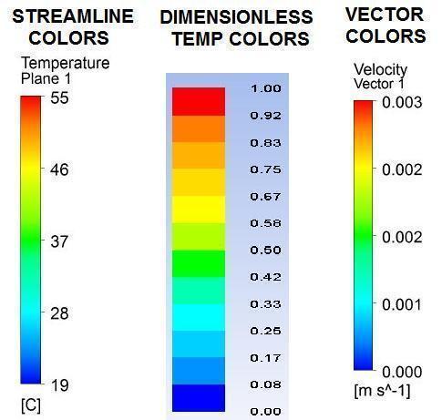
2 Coyle, 2 Abstract... 4 Introduction... 4 Literature Review... 5 Description of the Studied Problem... 8 Description of Geometry... 9 Governing Equations Discretization of Governing Equations Evaluation of Gradients and Derivatives Flowchart of Computation/Solution Algorithm Grid Application Boundary Conditions Working Fluids and Their Properties Discussion Grid Independence and Flow Patterns Results Images Streamlines, Contours and Vector Plots Conclusions Acknowledgements References Table of Figures Figure 1--Cube Enclosure Geometry... 9 Figure 2 Simple 3-point grid for 1-D discretization Figure 3 Variation of between x= 0 and x= L Figure 4 9-point grid for 2-D discretization Figure 5--Flowchart of the Segregated Pressure Solver Figure 6 Screenshot of Meshed Geometry with cells Figure 7--Diagram of Boundary Conditions Figure 8 Grid Independence Graph Figure 9--Example of a toroid shape. (Source: Wikipedia.org) Figure 10--Comparison of Streamlines for Condition Figure 11--Velocity Vectors for Condition 2, 100% Glycerol, Case E Figure 12---Velocity Vector Plot of Condition 3, 100% Water, Case E Figure 13--Diagram of Results Planes Figure 14 Color Legend for Table Figure 15 Color Legend for Table Figure 16 Color Legend for Table Figure 17 Color Legend for Table Figure 18 Color Legend for Table Figure 19 Color Legend for Table Figure 20 Color Legend for Table Figure 21 Color Legend for Table
3 Coyle, 3 Figure 22 Color Legend for Table Tables List Table 1--2-D Discretization Equation Variables Table 2--Applied Temperature Differences Table 3 Heat Flux Data for Grid Independence Table 4 Condition 1, 100% Glycerol Table 5 Condition 1, 86.7% Glycerol-13.3% Water Table 6 Condition 1, 100% Water Table 7 Condition 2, 100% Glycerol Table 8 Condition 2, 86.7% Glycerol-13.3% Water Table 9 Condition 2, 100% Water Table 10 Condition 3, 100% Glycerol Table 11 Condition 3, 86.7% Glycerol-13.3% Water Table 12 Condition 3, 100% Water Nomenclature Greek α Thermal Diffusivity (m 2 /s) β Vol. Thermal Expansion (1/K) or (1/ C) Γ Diffusion coefficient µ Dynamic Viscosity (kg/m-s) ν Kinematic Viscosity (m 2 /s) ρ Density (kg/m 3 ) Dimensionless Temperature, (T-T C ) / (T H -T C ) General property variable c p Specific Heat (J/kg-K) D Diffusion conductance F Flow rate through a control volume face g Gravitational Acceleration (g=9.81 m/s 2 ) h Height of cube enclosure side (1 inch or m) J Total (convection + diffusion ) flux through a boundary k Thermal Conductivity (W/m-K) L Characteristic Length (m), L = h P Pressure (1 Pa = 1 N/m 2 ) S Source term in discretization equations T Temperature ( C or K) u, U Velocity along x-direction (m/s) v, V Velocity along y-direction (m/s) w, W Velocity along z-direction (m/s) Gr Grashof Number Nu Nusselt Number Nu= (h L / k) Pe Peclet Number Pe = (ρul / Γ) Pr Prandtl Number Pr = (ν / α) Ra Rayleigh Number
4 Coyle, 4 Abstract The present work is an analysis of laminar natural convection of a 3D liquid-filled enclosure. A classical problem in engineering, this topic has been researched for many decades because it has several applications in both natural and synthetic processes. One such process is the hydrothermal method for growing crystals of quartz and semiconductors, which takes place in large autoclaves at high temperature and pressure. A study using the ANSYS/FLUENT software package has been completed in this project, whereby many parameters of the problem have been varied to determine their effect on the flow. These parameters include multiple temperature differences, three different working fluids (Glycerin, Water, and a Glycerin-Water solution), and different boundary conditions. Altogether, this creates 42 unique scenarios, visualized with temperature profiles, streamlines and velocity vectors for each case. The following conclusions were drawn: 1) the temperature contours in all cases were found to be horizontally stratified; and 2) distinct, symmetric cells of circulating flow exist and tend to break down, becoming more chaotic as the fluid is changed from glycerin to water. This investigation is significant because the results could possibly be extrapolated and used to optimize the process of hydrothermal crystal growth in industrial applications. Introduction Natural convection is convective heat transfer associated with the motion of a fluid body without external influence, but rather, due to density changes resulting from an imposed temperature gradient. This mechanism plays an important role in many naturally occurring processes, such as oceanic currents and the circulation of air within the earth s atmosphere, which contributes to weather patterns. In addition, natural convection is utilized in engineering processes such as the design of solar collectors, nuclear reactors, and most notably in the growth of synthetic crystals using a hydrothermal autoclave. Natural convection in enclosures has been the subject of extensive research for nearly half a century. The research can be classified primarily by one of two heating configurations: 1) heated from the side, and 2) heated from below. Subcategories of natural convection investigations are laminar flow, turbulent flow, choice of Prandtl number (working fluid) and various boundary conditions. Virtually any enclosure geometry imaginable has been studied, but the most common is a rectangular shape, based on its ease of modeling and meshing. Historically, only two-dimensional cases could be studied in detail, but with improvements in computational power and accuracy within the last few decades, research in this area has broadened to include three-dimensional flows.
5 Coyle, 5 Literature Review One of the earliest investigations related to natural convection, although not frequently cited in the literature, was an experiment run by Schmidt and Saunders [1] whereby a fluid (water and air; tested separately) was placed between two horizontal plates with various temperature differences imposed between the bottom and top plates, to determine the effect on flow. They observed that as the fluid was heated from below, instabilities and roll cells would develop, leading to turbulent flow when the Grashof number reaches 45,000 for liquid water and 5,000 for air, yet occurring much more slowly for air. Observations were made for temperature gradients and rate of heat transfer as flow transitioned from stagnant to cellular to turbulent, but the researchers did not make yet see the connection with free convection phenomena. Globe and Dropkin [2] however, performed the same type of experiment years later using mercury, silicone oils of 1.5, 50, and 1000 centistokes (kinematic) viscosities, and water, to provide a range of Prandtl numbers from 0.02 to The test apparatus was an insulated circular cylinder, sealed by copper plates that were heated from below with an electric heater. The collected results were used to form a Nusselt number correlation using the Rayleigh and Prandtl numbers, Nu 0.069( Ra) 1/ 3 (Pr) 0.074, which has been cited by many researchers and even referenced in introductory-level heat transfer textbooks [3]. Elder [4,5] was one of the first to investigate free convection experimentally for a rectangular enclosure in both the laminar flow regime (Ra<10 8 ), and the turbulent flow regime (Ra>10 8 ). In both studies, he prescribed a rectangular enclosure heated from the side with varying aspect ratios, to give geometries which he termed vertical slots. Elder observed growing boundary layers near the vertical boundaries for the primary flow, with a non-zero vertical temperature gradient. In addition, he noted the appearance of a cat s-eye pattern of multiple flow cells for Ra 10 5 which he classified as secondary and tertiary flows. Similarly, for turbulent flow at large Rayleigh numbers, he characterized the flow cavity into three regions: a sub layer of thermal conduction only, a transitional mixing region and fully chaotic interior. Wilkes and Churchill [6] performed a numerical study of flow using the finite-difference method, of 2-D rectangular enclosures heated from the side for both transient and steady state cases. Through this work, they were able to generate solutions which agreed with the analytical solutions available to them, for flow with Grashof numbers up to 100,000. This paved the way for numerical methods to be credible enough to be used as a predictive tool, able to validate experimental results in complex free convection cases. Aziz and Hellums [7] were apparently the first to use numerical finite difference methods to calculate the solutions to the dimensionless Navier-Stokes equations (written in terms of
6 Coyle, 6 vector potential and vorticity) for a transient, laminar, three-dimensional case where a rectangular enclosure is heated from below. They claimed that they were unable to find any previous works to accomplish this task successfully, due to high computational demands and the difficulties of applying 2-D implicit numerical methods to work in 3-D space. Barakos et al. [8] revisited the 2-D square cavity heated from the side problem, which is generally considered a benchmark case to verify numerical solutions. Both laminar and turbulent flows were considered, with Rayleigh numbers up to Their work implemented a finite volume method with uniform and non-uniform (stretched) grids of various sizes to resolve possible inaccuracies with growing boundary layers near the walls of the enclosure. Additionally, turbulence in the flow was modeled using the k-ε method with and without the use of logarithmic functions to calculate variables such as u, v, T, k, and ε at cells near the walls. After comparing this work to the previous literature, the solution was found to be in good agreement with De Vahl Davis [9] benchmark values, along with numerically and experimentally derived Nusselt number correlations with Ra number. Ostrach [10] and Catton [11] both provided extensive reviews of the major research done. Catton s work includes vertical (side-heated), horizontal (bottom heated) and tilted rectangular geometries as well as the special case of honeycomb geometries, found in solar panel applications. Catton also synthesizes many existing works to provide insight into heat transfer correlations and critical ranges of Rayleigh number where significant phenomena occur in both the laminar and turbulent regimes. Ostrach covers only rectangular enclosures heated from the side for the pure conduction regime, boundary layer regime, the transfer to turbulence, and horizontal circular cylinder cases. More recently, Ganguli et al. [12] have provided a comprehensive review of the most prominent works related to 2D narrow vertical enclosures, as well as running their own simulations for different slot heights, widths, and temperature differences to provide general heat transfer correlations that take all of these parameters into effect. Such a correlation would be useful when trying to reduce heat losses from a narrow air gap, as is frequently considered in the design of insulative windows and walls. There has been considerable research done on 2-D and 3-D cases of the rectangular enclosure with different combinations of boundary conditions imposed on the horizontal and vertical walls. A 2D square geometry with linearly heated vertical walls, an adiabatic top surface, and isothermal heating at the bottom surface was proposed by Sathiyamoorthy et al., [13] using a penalty finite element method. Flow properties were varied to give Prandtl numbers ranging from , and Rayleigh numbers on the orders of 10 3 Ra Comparative cases were also setup with only one linear vertical wall and the opposite cooled at a constant low temperature, with the horizontal boundaries unchanged. Streamlines for the flow for Pr=0.7 as the Rayleigh numbers increase show two large symmetric cells which decay to four smaller roll
7 Coyle, 7 cells once secondary flows begin to develop in the lower corners after Ra=5x10 4. This effect creates enhanced local mixing, leading to oscillations of Nusselt number but contributes to an overall increase in the average Nusselt number, meaning greater heat transfer. Ganzarolli and Milanez [14] experimented with uniform heat flux and isothermal heating at the bottom boundary while making the top surface adiabatic, for various aspect ratios, Prandtl numbers and Ra numbers. Several combinations of boundary conditions for the vertical surfaces were implemented by Corcione [15], while each enclosure remained heated from below at a temperature T H and cooled on top to a given T C. This included the scenarios of (i.) both sidewalls adiabatic, (ii.) one sidewall adiabatic and the opposite wall at T H (or T C ), and (iii.) both sidewalls at T H (or T C ). Many conclusions were drawn, but the most significant appears to be that the heat transfer rates across the horizontal surfaces were found to increase between cases when the adiabatic walls were replaced by isothermal ones. Rahman and Sharif [16] conducted a parametric study of inclined rectangular enclosures of various aspect ratios, with and without internal heat generation to find that the streamlines and isotherms largely remained the same for either case. Mallinson and G. de Vahl Davis [17] studied a 3D variable aspect ratio rectangular box heated from the sides, with Prandtl numbers up to 100, for 10 4 Ra They found the occurrence of certain end effects (near the longitudinal ends of the cavity) resulting from two mechanisms dependent on the Prandtl number: at low Pr, inertial forces dominate but as Pr grows large a thermal end effect is present. Fusegi et al. [18] investigated a 3-D air-filled cube for Ra=10 5, and Ra=10 6 with two of the vertical sidewalls being differentially heated to a constant temperature, and the other vertical walls insulated. The horizontal surfaces were either made adiabatic or perfectly conductive with a linear temperature gradient. Pallarès et al. [19] prescribed an air-filled cube heated from below, cooled at the top face, with all vertical sidewalls adiabatic. The flow considered was time dependent and laminar, for small Ra (3500 Ra 10,000) with single and toroidal swirling flows observed at critical values of Ra. Divided enclosures with either an impenetrable partition or a restrictive baffle have also been widely investigated to see what the effect of inhibiting heat/mass transfer has on natural convection mechanisms. Shaw and Chen [20] conducted parametric studies of a 2D bottomheated enclosure with adiabatic sidewalls and a horizontal partition at various heights. A parametric study was carried out by Kangni et al., [21] for laminar free convection with air-filled cavities. Several variations in parameters were exploited in this work: the number of partitions, the ratio of thermal conductivity between fluid and partition, and three different aspect ratios, all to gain a better understanding of how partitions can reduce heat transfer. Li et al. [22, 23] conducted parametric studies of bottom-heated, top-cooled cubical enclosures with a baffle plate positioned at mid-height. These studies were then validated by an
8 Coyle, 8 experimental setup which used thermo-chromic liquid crystals (TLC) 1 and inert particles in order to visualize the temperature and velocity fields of the flow. A mixture of 83.4% glycerol % water with the same density as the visualization particles was used as the working fluid. It would appear that these cases are constructed such that they would simulate a simple autoclave for hydrothermal crystal growth, on a much smaller scale. Cuckovic-Dzodzo et al. [24] investigated, using a computational and experimental setup, cubical enclosures heated from the side with and without a vertical partition using pure glycerol as the working fluid. Steady free convection flow occurred in the laminar regime for Rayleigh numbers of 38,000 Ra 369,000. The Boussinesq approximation was not used variation of the thermodynamic properties of glycerol with temperature was considered and implemented into the model via polynomial equations for the density, conductivity, specific heat, and viscosity. A similar experimental setup to Li [22, 23] was used to validate the numerical results. The researchers found that the convective heat transfer was reduced by approximately 60% with the addition of a complete vertical partition. While the two most common fluids considered in numerical convection cases have been air (Pr = 0.71) and water (Pr = ~6), other fluids with higher viscosities, such as glycerin and various oil mixtures, have been studied to investigate the effect of high Prandtl number fluids. Younis et al. [25] used Golden syrup 3, Glycerin, and a 50% Glycerin-Water mixture as three different working fluids to provide Prandtl numbers ranging from 3x10 5 > Pr > 50, respectively. Each fluid was studied in a 3D, transient, laminar flow setup with Rayleigh numbers of 5x10 6 and 5x10 7. Instead of heating the fluids with an imposed temperature difference across the cube, the fluids were modeled as being hot with the surrounding walls held at the same constant lower temperature, to allow cooling over time. They found that for low Ra, symmetric thermal plumes appear, the size of which are inversely proportional to the Prandtl number. It was also concluded that the Nusselt number is largely dependent on the initial Rayleigh number, and independent of the Prandtl number. Description of the Studied Problem The problem studied in this paper involves natural convection in a liquid-filled 3-D cubical enclosure heated from below and cooled on top. A parametric study is conducted using the ANSYS Workbench/Fluent 12.0 software, a commercially available computational fluid 1 Thermo-chromic liquid crystals are particles which change color based on the surrounding temperature. 2 Glycerol is another name for glycerin. The chemical formula is C 3 H 5 (OH) 3. 3 Golden syrup is a popular sweetener in the UK, made from sugar cane juice. Its amber color makes it similar to honey in appearance but it is closer to corn syrup, in terms of viscosity.
, for Rayleigh numbers in the range")
9 Coyle, 9 dynamics package. This concerns steady, laminar flow utilizing the Boussinesq approximation (which states that density only varies in the body force term of the y-momentum equation), for Rayleigh numbers in the range of 10 3 to The variable parameters are the boundary conditions, temperature differences (ranging from 2-35 C), working fluids 100% water, 100% glycerol, and a 86.7% glycerol-water mixture which gives the following range of Prandtl numbers ,500. Description of Geometry Figure 1--Cube Enclosure Geometry Throughout the work, the geometry remains constant for all of the numerical simulations. Figure 1 shows the problem geometry: a solid 1 X 1 X 1 (25.4 mm X 25.4 mm X 25.4 mm) 3- D model was created using the Design Modeler program built into the ANSYS Workbench interface. For the majority of the simulations no wall thickness is specified such that the temperature boundary conditions are applied directly to the fluid interfaces. However, for a few of the cases where the vertical walls of the enclosure are considered adiabatic, the heated surfaces (top and bottom walls) were set to 1/8 thickness (3.175 mm) to correct an anomaly 4 related to the pressure gradient at the boundaries. 4 Looking at a vector plot, the velocity vectors appear to be coming out of the cube enclosure.. According to the ANSYS/Fluent help file, the Standard Pressure interpolation scheme assumes that the normal pressure gradient at the wall is zero the failure to correctly account for the wall pressure gradient is manifested in velocity vectors pointing in/out of walls. This was indeed the case, because the Standard scheme was used in all simulations.
10 Coyle, 10 Governing Equations Nearly all problems involving fluid flow rely on the Navier-Stokes equations of momentum to govern the flow of a viscous fluid. For the problem at hand, we consider natural convection inside a three dimensional enclosure using the Cartesian coordinate system (utilizing x,y,z as the primary directions and u,v,w, as the velocity components). To solve each case in this problem, Fluent solves five equations simultaneously: the continuity equation, one momentum equation each for the x-, y-, and z-directions, and the energy equation. To simplify the problem we deal with steady-state flow under the Boussinesq approximation, along with constant properties. In addition, the only driving force is the body force term in the y-direction (vertical direction) no forces act in the x or z-directions. Thus, the equations can be written in scalar form as follows: Continuity: X-Direction Momentum: Y-Direction Momentum: Z-Direction Momentum:
11 Coyle, 11 Energy Equation: The Boussinesq Approximation The region of fluid furthest from the boundaries can be considered quiescent, characterized by little to no fluid motion relative to the surroundings. The properties of this region are called free-stream properties and denoted with a subscript. Thus, with no motion (v=0), the y-momentum equation reduces to the pressure gradient equaling the body force term, or: Substitution of this relation back into the y-momentum equation, and dividing through by density yields the following expression: The driving force in the flow is represented by the source term of the y-momentum equation, which accounts for the interaction between gravity and buoyancy. For a liquid, only a change in temperature will cause a change in the density the sensitivity to this effect is related to the volumetric thermal expansion coefficient, β. By approximating the differential, the definition can be rearranged to obtain: this is known as the Boussinesq approximation. Substituting this back into the y-momentum equation results in the following equation (shown on the next page):
12 Coyle, 12 In this formulation, the importance of the temperature difference,, is clearly shown. For this parametric study, the temperature difference is defined instead as, which is the difference between hot and cold boundary temperatures. The Boussinesq approximation simplifies the flow equations by eliminating density from all terms except the y-direction source term, but also has the effect of strongly coupling the energy and momentum equations, which now all depend on the fluid temperature, T. Dimensionless Parameters The analysis of natural convection is also greatly simplified by dealing with dimensionless parameters. The first step toward deriving these involves non-dimensionalizing all of the important variables: Using the above variables, the governing equations introduced earlier can now be re-written in a dimensionless form: Continuity: X - Momentum
13 Coyle, 13 Y-Momentum Z-Momentum Energy Equation The variable represents a reference velocity that normalizes the other velocity variables. For convenience, it can be set to, which simplifies the boxed source term, and allows two important dimensionless groups to emerge: the Prandtl number (Pr), and the Grashof number (Gr L ). The Prandtl number is the ratio of the momentum and thermal diffusivities for a particular fluid, which controls the relative thicknesses between the momentum and thermal boundary layers. The Grashof number is analogous to a Reynolds number; it is the ratio of buoyancy forces to viscous forces in the flow, based on some characteristic length scale. By taking the product of the Gr and Pr numbers, the Rayleigh number (Ra L ) is defined, which is the key parameter in characterizing natural convection: Empirical studies have shown that in general, the following rules apply when classifying natural convection flow:
14 Coyle, 14 No convection; conduction only Laminar natural convection Transition to turbulence Turbulent natural convection To reduce computational time and complexity, only a laminar flow model is used in Fluent for all of the cases. Discretization of Governing Equations The exact solution to a differential equation for any dependent variable φ (i.e. pressure, or temperature) is an infinite or continuous set of numbers, which is very difficult to obtain. When performing computational fluid dynamics, the ultimate goal is to generate a finite solution of discrete values for φ, which is not exact, but close enough, for our purposes. There are many different methods of discretization (which will be mentioned later) but all share a common approach: create a set of polynomial equations to determine the variable φ at discrete locations in a given flow field, and choose an algorithm by which to solve these equations. A discretization equation is a linear algebraic equation which relates the values of a general variable φ to a small group of local grid points via coefficients. Essentially, through iterative numerical methods this allows us to solve differential equations not by complex integration, but through addition of fluxes in and out of a control volume. One-Dimensional Discretization This derivation is by no means original material--it will closely follow the approach taken by S. Patankar [26]. We assume (by initial guess) that the property of interest is known at certain points surrounding a control volume, and a method of interpolation is necessary to calculate the change in the property between grid points (or nodes). Let represent a general variable of interest which can be transported ( or advected ) with the flow and let Γ represent the diffusion coefficient in the expression. To begin the derivation, consider the simplest case: a one-dimensional flow with three grid points, as shown in Figure 2. The capital letters (W, P, and E) are node points, while the lower case letters (w, e) are the west and east boundaries of the control volume.
15 Coyle, 15 Figure 2 Simple 3-point grid for 1-D discretization. (Image scanned from Patankar[26], p.81) The governing differential equation for convection/diffusion in one dimension is: For this situation this equation over the control volume in Figure 2 gives: (flow in = flow out), by the continuity equation. Integrating For now, the property can be interpolated at the boundaries of the control volume by assuming is the average value between the node values. This is a flawed approach; it will need to be corrected later so the problem will remain physically realistic. and Substituting these into the above equation yields The Upwinding Scheme derivations: For simplicity two new variables, F and D, are defined which will be used often in further
16 Coyle, 16 These symbols are more than just placeholders F represents the strength and direction of the flow, while D is a diffusion conductivity, much like k is to thermal conduction. Because F can be positive or negative, this could lead to unrealistic values of, as mentioned earlier. Instead of taking an average of between the node points, a method known as the upwind scheme is proposed. This method states that the value of at a boundary is equal to the value at the upwind (or upstream) node point, depending on the direction of the flow. For example, if in Figure 2, liquid flows from E to P (in the negative x direction), the value at the east boundary, is set equal to the value at the upstream node point. Applying the upwind scheme and the variables F and D, the following discretization equation can be written as with these coefficients: The notation within these coefficients is a consequence of the upwind scheme it means select the greater of the two quantities I and J, and takes into account sign and magnitude. The Exact Solution and the Importance of the Peclet Number It is possible to solve the one-dimensional case exactly if certain conditions are met. Specifically, the diffusion coefficient Γ must be constant, along with the ρu term in the continuity equation. If these are satisfied, and a domain is used, with the boundary conditions At x = 0 At x = L
17 Coyle, 17 The solution becomes: The symbol Pe is the Peclet number, a dimensionless ratio between the rates of advection and diffusion within the fluid. (The term advection is often used interchangeably with convection but specifically refers to the transport of a property with a fluid as it flows, like a canoe traveling down a river.) Figure 3 Variation of between x= 0 and x= L. (Image scanned from Patankar [26], p. 86) Figure 3 shows a plot of the solution the variation of the property and its dependence on the Peclet number is given. When the Peclet number is zero, there is a linear relation between and x, since the heat is transferred entirely through diffusion (conduction). Conversely, for very large Peclet numbers, ( ), convection dominates and there is not much variation of with x. Essentially, there is no diffusion of the property (i.e., ) across most of the domain, and it remains consistent with the upwind scheme in that the upstream property dominates. For cases where the advection and diffusion strengths are nearly equal, a
18 Coyle, 18 balance of convection and conduction heat transfer occurs. This approximates a linear variation, influenced slightly by the upstream value. Discretization in Two- and Three- Dimensions Figure 4 9-point grid for 2-D discretization The discretization approach defined here can be expanded to include two and threedimensional geometries. For the 2-D case, consider a grid of nine node points and a control volume surrounding the central node of interest, P, as shown in Figure 4. The control volume now has four boundaries: north, south, east and west, and corresponding nodes for each face. The governing equation can be written in a more compact form by defining a total flux J that combines the convection flux and the diffusion flux. A total flux expression can be written for both x and y directions, as follows: The two-dimensional steady-state forms of the continuity and transport equations are
19 Coyle, 19 Integrating the transport equation over the control volume in Figure 4 yields: Similarly, the continuity equation can be integrated over the control volume to give: Multiplying this equation through by and subtracting it from the previous formula, results in: Several terms, such as F, D, J and Pe for each boundary of the control volume are defined and summarized in Table 1. Control Volume Boundary East Table 1--2-D Discretization Equation Variables Integrated Total Fluxes Flow Rates Diffusion Conductance Peclet Numbers West North South Like the one-dimensional case, a final discretization equation can be written in this way: Where
20 Coyle, 20 The terms in all of the discretization constant equations allow for different interpolation methods to be implemented, such as the upwind, exponential, central-difference, power law, and hybrid schemes. For this project, only the upwind scheme was used, so for all cases. A three-dimensional discretization will not be described in this paper, because it would become redundant. By adding two additional neighboring grid points along the z-axis (into/out of the page), the same sort of discretization approach as before could be completed, adding only eight more terms (two of each of flow rate F, diffusion conductance D, general coefficient a, and Peclet numbers Pe) to the equations already derived. Evaluation of Gradients and Derivatives A second-order upwind scheme was used to solve the momentum and energy equations in Fluent. Like the first-order upwind scheme, the face value is always set equal to the value of at the center of the upstream cell. However, to achieve second-order accuracy a Taylor series expansion of the cell-center value is implemented, which takes into account the gradient of φ and the direction using the following formula: Where: Gradients are evaluated using the Least Squares Cell-Based method, which is the default operation used by Fluent because it requires the least computational resources while still providing high accuracy. The Least Squares method assumes that the solution varies linearly, such that the change in values between adjacent cells can be represented simply as a difference, as seen in the following equation. Suppose one region of the mesh has a group of cells, with c 0 as
21 Coyle, 21 the centroid of the center cell, and c I, as the centroid of a neighboring (downstream) cell. The gradient of from c 0 to c I is: Other equations can be formulated for the gradient when passing from c 0 to any other adjacent cell, in a similar (yet more compact) manner: The [G] matrix that appears is based on the specific geometry of the mesh, essentially just a holder for the coefficients of the vectors. The resulting linear system of these equations can be solved by decomposition of the matrix of coefficients using the Gram-Schmidt process, which results in a matrix of weighting values for each face of the cell c 0. By multiplying the difference vector with the sum of the weight factor components in a particular direction, the gradient is determined. Combining the results of these three equations yields the gradient: When using the second-order upwind scheme, Fluent applies gradient limiters to prevent the calculated gradients from becoming unrealistic or generating false oscillations in the flow, which could distort the final solution. The gradient limiter helps to impose a monotonic (one way; upstream to downstream) gradient, by ensuring that the newly calculated face values cannot exceed the maximum or minimum values of for the adjacent cells.
22 Coyle, 22 Flowchart of Computation/Solution Algorithm The Fluent interface has two solver types to choose from when setting up a particular simulation: pressure-based and density-based. According to the Fluent Help manual, the pressure-based solver employs an algorithm which belongs to a general class of methods called the projection method. The main facet of the projection method is that the velocity field is generated by solving a pressure correction equation derived from all of the momentum and continuity equations, which are inherently coupled to the pressure and velocity field. Essentially, a preliminary solution of the velocity field and mass fluxes are acquired by solving the equations of momentum using the user inputs (initial properties, boundary conditions and operating conditions) which are then corrected by the pressure equation to satisfy continuity. Although the governing equations are non-linear and coupled, they can be de-coupled or segregated to solve for the flow variables (such as u, v, w, T, and p) individually. The segregated pressure-based algorithm is not the fastest method of convergence but makes the most effective use of available computer resources because it requires that only the equation currently being solved needs to be stored in memory. The SIMPLE (Semi-Implicit Method for Pressure Linked Equations) algorithm [26] was used to solve the set of equations in Fluent. Considering the momentum discretization equations derived in the Discretization section earlier, the pressure gradient acting on the control volume faces can be included for all three directions as follows: The subscript nb denotes neighbor cells; n, e, t, and p refer to the boundaries between nodes N, E, T, and P, (North, East, Top and starting Point) respectively. The A terms are the areas of the control volume faces that the pressure differences act upon, which are: The b terms are source variables, which include a source coefficient times the volume, which is given in the following expression.
23 Coyle, 23 Once the pressure field p* is guessed, it can be substituted into the previous equations and the approximate (uncorrected) values of the velocities, u*, v* and w* can be obtained: An important simplification is that Patankar [26] drops the terms from all equations concerning u, v, and w from here on, without any consequences. This is the reasoning behind the semi-implicit name the removed term, in itself represents an implicit influence of the pressure correction on velocity, [26] based on the pressures in the neighboring cells. It is recommended that we avoid dealing with the neighboring nodes effect, which would complicate the entire process. Next, equations for the true pressure and velocity terms can be constructed. The general form is the guessed value ( starred ) plus some correction factor, ( primed terms) which is defined here: Relaxation factors κ p and κ m for pressure and momentum are introduced to help prevent the correction equations from causing divergence. In this particular case, the under-relaxation factors used are κ p =0.3 and κ m = , depending on the boundary conditions chosen. To derive the velocity correction equations u, v, and w, we simply subtract the starred discretization equations from the ones first derived as such: This becomes: Solving for yields the velocity correction for the x-direction,
24 Coyle, 24 with This expression can be added to u*, the guessed velocity, to yield the actual velocity passing through the east boundary: Similar equations for the v and w velocities can be written, simply by changing the subscripts to their corresponding values. The final step is to derive the equation of the pressure correction p by integrating the continuity equation over the chosen control volume. Substituting in the equations for discretization equation for p : obtained previously and rearranging yields the Each of the a coefficients takes the general form as the product of density, the d ratio, and the face area A ( for the north, south, east, west, top, and bottom faces), in the following manner: Lastly, the source term, b, of the pressure correction equation is as such: Combining all of the discretized pressure and velocity equations, the system of equations can be organized as an overall solution algorithm. After the case is initialized with initial guesses of velocity, pressure and temperature values, the solver can begin calculating. The initialization can be arbitrary, but needs to be somewhat realistic to ensure convergence-- it would not be wise to input a starting temperature outside the limits imposed by the temperature difference, (i.e., T H and T C. ).
25 Coyle, 25 According to Section of the Fluent Theory Guide help file [27], each iteration of the segregated algorithm is comprised of the following steps: 1. Update fluid properties (temperature, viscosity, etc.) based on the current solution. 2. Solve the momentum equations, one after another, using the recently updated values of pressure and face mass fluxes. 3. Obtain the pressure correction equation using the recently obtained velocity field and the mass-flux. 4. Correct face mass fluxes, pressure, and velocity field using the pressure correction obtained from Step Solve additional scalar transport equations, such as energy, radiation intensity, species transport or turbulent quantities (if applicable) using the current values of the solution variables. 6. Update the source terms arising from interactions among different phases if applicable. 7. Check for convergence of the equations based on the residuals criterion set in the Solution Monitors. If the equations are not converged, return to step one. (The process is also summarized in the flowchart shown in Figure 5) Figure 5--Flowchart of the Segregated Pressure Solver.
![Coyle, 26 The SIMPLE method as outlined by Patankar [26] is a sub-routine of Steps 2, 3, and 4 of the Fluent solver procedure, and consists of these six steps: 1.](/docs-images/74/69880017/images/26-0.jpg "Make an initial guess of the pressure field p*. 2. Solve the discretized momentum equations, to obtain approximate values for the velocities: u*, v*, w*. 3. Solve the p equation. 4.")
26 Coyle, 26 The SIMPLE method as outlined by Patankar [26] is a sub-routine of Steps 2, 3, and 4 of the Fluent solver procedure, and consists of these six steps: 1. Make an initial guess of the pressure field p*. 2. Solve the discretized momentum equations, to obtain approximate values for the velocities: u*, v*, w*. 3. Solve the p equation. 4. Calculate p by adding p to p* 5. Calculate u, v, and w from their starred values using the velocity-correction equations. 6. Treat the corrected pressure p as a new guessed pressure p*, return to step two, and repeat the procedure until convergence. Grid Application A uniform grid of square elements was applied to the cube geometry using the ANSYS Meshing program. The grid size chosen for all cases was 49 X 49 X 49, which yields elements (cells, or volumes). This was chosen to allow reasonable accuracy while minimizing computational power and time necessary for the solution to converge. A grid convergence exercise was performed to determine which grid size is the most efficient, and if the solution is truly grid independent. This would mean that, as the grid size is increased further and further, there is a point where the solutions will no longer change significantly. The results are shown in Table 3 of the Results section. Figure 6 Screenshot of Meshed Geometry with cells
27 Coyle, 27 Boundary Conditions A key parameter in this investigation is the temperature difference, T, which is imposed on the enclosure. This temperature difference is defined by the following equation: where T H is the hot temperature at the bottom surface of the cube, and T C is the cold temperature at the top surface of the cube. Additionally, an average temperature, T Avg, was defined by simply taking the arithmetic mean of the two temperatures. All fluid properties were determined at this average temperature. Refer to Table 2 for the complete list of temperature differences. Table 2--Applied Temperature Differences Case Difference T C T avg T H A B C D E F G H J The temperature differences labeled A-D are taken from Cuckovic-Dzodzo [24], because they provided a good range of Rayleigh numbers and the material properties of glycerin would be reasonably similar. Temperature differences E-J were created for the present work to allow for variation of fluid properties, especially the Grashof and Rayleigh numbers. In this parametric study, three different types of boundary conditions were imposed on the vertical walls of the enclosure model: an adiabatic condition, an isothermal condition, and a linear temperature gradient condition. For the three fluids considered (100% Glycerol, 86.7%-

28 Coyle, % Glycerol-Water Mixture, and 100% Water) at each temperature difference, one case with each boundary condition was run, for a grand total of 42 simulations. Each case was setup using the Boundary Conditions tab of the Fluent setup window. Figure 7--Diagram of Boundary Conditions Condition 1--The adiabatic boundary condition cases. The vertical walls were defined with a constant zero heat flux. Originally, it was planned to use the same five temperature differences (A-E) for all three boundary conditions. However, after preliminary runs of Fluent it was determined that these cases require a set of much smaller temperature differences (F-J) due to slow or no convergence at all. Ultimately, this occurred with the larger temperature gradients because a great amount of heat is input to the fluid via the bottom wall, which is not rejected to the surroundings. This lack of thermal dissipation does not allow circulation caused by density variations, thereby inhibiting convection. Condition 2--The isothermal boundary condition cases. The vertical walls were set with a constant temperature equal to the average temperature of the particular temperature difference at hand. All four walls were set to the same temperature. Condition 3--The linear temperature gradient walls. This condition was established by writing a UDF (User Defined Function) file in the C+ language and commanding Fluent to interpret the file into its native programming language. This process was done each of the temperature differences A-E. Unlike the previous two boundary conditions, which are built-in options in Fluent, this had to be defined, debugged and uploaded manually into the project files
29 Coyle, 29 to provide additional functionality. Using the two known temperatures and their corresponding locations in the y-direction (top or bottom surfaces) a slope was calculated and an equation of the gradient was derived: T(y) = b + my T y T y C H m 0 and b T H top bottom 0 y m Note: All temperatures are absolute, in the Kelvin scale. A UDF code was created for each temperature difference in the C+ language, which could be read into Fluent. These code files can be found in the appendix. Working Fluids and Their Properties Three fluids, each a solution of water and glycerin in different proportions by weight, were used in this numerical investigation: 100% glycerin, 86.7% -13.3% glycerin-water, and 100% water. The properties of 100% Water were taken from the NIST REFPROP software [28], which uses formulas based on the NIST database of material properties to calculate saturation and iso-property tables in terms of any two thermodynamic state variables. The properties of 100% Glycerin solution were calculated using the polynomial equations found in Cuckovic- Dzodzo [24] and from the OPTIM Glycerin [29] data sheets available online from DOW Chemical Corp. (See the appendix for details.) Properties of the glycerin-water mixture were determined mainly from polynomial curve fits generated for experimental data available from the book Glycerol and the Glycols [30]. Microsoft Excel was used to plot the experimental data, generate the required polynomial curve fits, which were then used to interpolate properties at the average temperature of each temperature difference A-J. Refer to the properties charts in the appendix for further details. Discussion Grid Independence and Flow Patterns For the grid independence exercise, five mesh sizes were applied to the cube geometry: 32 3, 48 3, 64 3, 80 3 and 89 3 cells. Each meshed cube was run through the same case setup in Fluent: isothermal vertical walls at the average temperature of the Case A T, which is a difference of 13.3 C across the enclosure vertically. The five cases were run to convergence
30 Coyle, 30 using the default criterion in Fluent, which requires the Y-velocity residual error to fall below 1 x After performing a simple heat balance check on each case, the simulations appear to have converged reasonably well, considering that the heat entering through the bottom face is always nearly equal to the heat leaving the top face, as shown in Table 3. While the heat flux appears to be increasing steadily as the mesh density is increased, this trend actually tapers off, suggesting that the solution becomes grid-independent for meshes larger than 89 3 cells. This is reflected in Table 3 and in the graph of Figure 8. Table 3 Heat Flux Data for Grid Independence Heat Flux 32x32x32 48x48x48 64x64x64 80x80x80 89x89x89 Q Top W W W W W Q Bottom W W W W W Net (Q T +Q B ) W W W W W Change from coarser mesh (%) N/A 7.5 % 5.1 % 3.0 % 1.2 % Note: All fluxes are shown in Watts (W) Figure 8 Grid Independence Graph
.")
 temperature variation.")
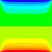
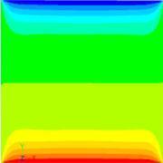
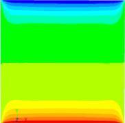
31 Coyle, 31 Discussion of Natural Convection Flow Results Refer to the images on pages of this report. Some general points can be made about the body of results as a whole: (with the exception of the Condition 2 cases, which are unique). The majority of the temperature contours are stratified vertically the temperature within the enclosure varies only through horizontal layers that progressively change from T H (bottom) to T C (top). There is no lateral (left to right) temperature variation. This is expected of Conditions 1 and 3, because of the boundary conditions in fact, the effect of a linear temperature gradient is to impose stratification. The majority of the cases are characterized by negligible velocity. This is shown in the color of the vector plots a color of blue on all of the velocity scales represents zero velocity. For nearly all cases with a clearly developed, multi-cellular flow pattern, the flow is toroidal within the enclosure (A toroid is a 3-dimensional doughnut shape, as illustrated in Figure 9). The images of 3D streamlines found in the Appendix show this more clearly. Figure 9--Example of a toroid shape. (Source: Wikipedia.org) The results of the Condition 1 simulations (with adiabatic vertical walls) possess the most dramatic changes when the fluid mixture and are modified. For all temperature differences (F-J), the cases with 100% Glycerol fluid have a weak 4-cell flow structure. As the fluid is

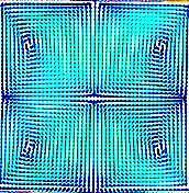
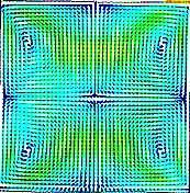
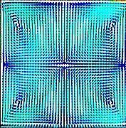
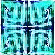
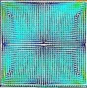
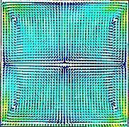
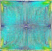
32 Coyle, 32 changed to 86.7% Glycerol-13.3% Water, (large decrease in viscosity) flow for the low temperature differences (2-5 C) show two symmetric cells that take up the entire volume. The remaining cases with higher do not have any developed or organized flow, which could suggest a transition phase between four-cell and two-cell flow structures. For the 100% Water cases, the circulation is definitely stronger, as indicated by the darker, overlapping streamlines, and some symmetry is present. The Condition 2 cases, with isothermal vertical walls, were the most interesting specimens of the entire parametric study. Streamlines for all three fluids and all s show a perfectly symmetric four-cell flow, which does not change much with temperature. As the fluid is changed from 100% Glycerol to 100% Water, the cell centers shift more toward the corners and distort the flow, as illustrated in Figure 10. Looking left-to-right on Tables 7-9, this effect occurs within each fluid as is increased, but to a lesser extent. Figure 10--Comparison of Streamlines for Condition 2 The Condition 2 temperature contours are markedly different from the Condition 1 and 3 cases. While there still are distinct horizontal layers of temperature near the center, they curve toward the corners, as expected for the growing thermal boundary layers. In these images, most of the enclosure is colored in olive or bright green colors, (matched to the mean temperature), which suggests that significant mixing and heat transfer is occurring. Lastly, the plots of velocity vectors are very colorful and dynamic and reflect the fully developed, four-cell flow shown in the streamline plots. A close-up of the velocity vector for 100% Glycerol, Case E (ΔT = 35 C) is shown in Figure 11.

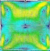
33 Coyle, 33 Figure 11--Velocity Vectors for Condition 2, 100% Glycerol, Case E The flow for the Condition 3 simulations, with a linear temperature gradient on the vertical walls also seems to change dramatically with variations of fluid and temperature difference. For all of the 100% Glycerol cases, the flow is comprised of two symmetric cells, which are very weak for Case A, (ΔT = 13.3 C) but grow to fill the entire cavity for Case D (ΔT=30.9 C). As the fluid is changed to include more water than glycerin, the flow becomes much less developed but keeps the familiar two-cell structure. When the working fluid is changed to 100% Water, multi-cellular flow is absent from the streamlines but remains symmetric laterally. For low temperature differences (13-18 C) the flow pattern resembles a flower-vase structure, which decays to small mustache-looking eddies that curl in the lower corners as the temperature increases. The temperatures are once again perfectly stratified from top to bottom, and are independent of the temperature boundary conditions or working fluids used. The velocity vectors for 100% Water appear increasingly disordered as the temperature increases. The Rayleigh numbers are of the order 10 7, which is approaching the laminar flow limit and the transition to turbulence range. Figure 12 is an enlarged vector plot to illustrate this concept.

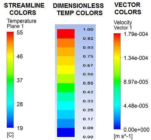
34 Coyle, 34 Figure 12---Velocity Vector Plot of Condition 3, 100% Water, Case E Results Images Streamlines, Contours and Vector Plots The following several pages present the results of the parametric study in the form of 2D streamlines, dimensionless temperature contours, and velocity vector plots. Three slice planes were created within the cube geometry for post-processing, as shown in Figure 13. This was done to compare the fully developed flow in the center of the enclosure with the developing boundary layer flow that exists near the walls. Plane 1 is located 0.5 inches (12.7 mm) from the wall, while Plane 2 is 0.1 inches (2.5 mm) from the same wall, which intersects the origin. Only the results for Plane 1 are represented in this section. Results for the near-wall plane, Plane 2, can be found in the appendix, along with images of 3-D streamlines. Data for the YZ-plane

35 Coyle, 35 (Plane 3) was omitted; the flow in all cases was found to be identical to the XY planes, due to symmetry of the boundary conditions. Figure 13--Diagram of Results Planes All of the pictures are organized into tables on the following pages, arranged first according to boundary condition, then by the working fluid used. A color-map legend for each group of images is shown below each table for reference. Streamlines are shown with a colored background that shows the temperature variation for the particular plane. Additionally, contours of dimensionless temperature for each case were created by plotting, using the Custom Field Function dialog box in Fluent. ( was defined previously in the Governing Equations section, under the sub-heading, Dimensionless Parameters). Tables 4-6 show the results for enclosures with adiabatic vertical walls (Condition 1). Tables 7-9 present the results for enclosures with isothermal vertical walls (Condition 2). Finally, Tables contain the results for enclosures with linear temperature gradient vertical walls (Condition 3).


 J (10.0 C) Ra 1.")

36 Vectors Temperature Streamlines Coyle, 36 Table 4 Condition 1, 100% Glycerol Fluid: 100% Glycerol Condition 1: Adiabatic Vertical Walls Plane: XY-mid-plane T F (2.0 C) G (5.0 C) H (7.0 C) J (10.0 C) Ra 1.49 X X X X 10 4 Figure 14 Color Legend for Table 2


 J (10.0 C) Ra 1.")

37 Vectors Temperature Streamlines Coyle, 37 Table 5 Condition 1, 86.7% Glycerol-13.3% Water Fluid: 86.7%-13.3% Plane: XY-midplane Condition 1: Adiabatic Walls Glycerol-Water T F (2.0 C) G (5.0 C) H (7.0 C) J (10.0 C) Ra 1.40 X X X X 10 4 Figure 15 Color Legend for Table 3


 T F")
 H (7.")
 Ra 4.")

38 Vectors Temperature Streamlines Coyle, 38 Table 6 Condition 1, 100% Water Fluid: 100% Water Condition 1: Adiabatic Walls Plane: 1 (XY-mid) T F (2.0 C) G (5.0 C) H (7.0 C) J (10.0 C) Ra 4.72 X X X X 10 6 Figure 16 Color Legend for Table 4


39 Vectors Temperature Streamlines Coyle, 39 Table 7 Condition 2, 100% Glycerol Fluid: 100% Glycerol Condition 2: Constant Wall Temperature (average of T) Plane: XY-mid-plane T A (13.3 C) B (18.0 C) C (26.2 C) D (30.9 C) E (35.0 C) Ra 1.64 X X X X X 10 5 Figure 17 Color Legend for Table 5


40 Vectors Temperature Streamlines Coyle, 40 Table 8 Condition 2, 86.7% Glycerol-13.3% Water Fluid:86.7%-13.3% Condition 2: Constant Wall Glycerol-Water Temperature (average of T) Plane: XY-mid-plane T A (13.3 C) B (18.0 C) C (26.2 C) D (30.9 C) E (35.0 C) Ra 1.48 X X X X X 10 6 Figure 18 Color Legend for Table 6


 C (26.")
 E (35.")

41 Vectors Temperature Streamlines Coyle, 41 Table 9 Condition 2, 100% Water Fluid: 100% Water Condition 2: Constant Wall Temperature (average of T) Plane: XY-mid-plane T A (13.3 C) B (18.0 C) C (26.2 C) D (30.9 C) E (35.0 C) Ra 4.47 X X X X X 10 7 Figure 19 Color Legend for Table 7


 C (26.")
 E (35.")


42 Vectors Temperature Streamlines Coyle, 42 Table 10 Condition 3, 100% Glycerol Fluid: 100% Glycerol Condition 3: Linear Temperature Gradient Plane: XY-mid-plane T A (13.3 C) B (18.0 C) C (26.2 C) D (30.9 C) E (35.0 C) Ra 1.64 X X X X X 10 5 Figure 20 Color Legend for Table 8


 B (18.")
 D (30.")
 T Ra 1.")
43 Vectors Temperature Streamlines Coyle, 43 Table 11 Condition 3, 86.7% Glycerol-13.3% Water Fluid: 86.7%-13.3% Condition 3: Linear Temperature Plane: XY-mid-plane Glycerol-Water Gradient A (13.3 C) B (18.0 C) C (26.2 C) D (30.9 C) E (35.0 C) T Ra 1.48 X X X X X 10 6 Figure 21 Color Legend for Table 9


 B (18.")
 D (30.")
 Ra 4.")

44 Vectors Temperature Streamlines Coyle, 44 Table 12 Condition 3, 100% Water Condition 3: Linear Temperature Fluid: 100% Water Plane: XY-mid-plane Gradient T A (13.3 C) B (18.0 C) C (26.2 C) D (30.9 C) E (35.0 C) Ra 4.47 X X X X X 10 7 Figure 22 Color Legend for Table 10
NATURAL CONVECTION OF AIR IN TILTED SQUARE CAVITIES WITH DIFFERENTIALLY HEATED OPPOSITE WALLS
 Proceedings of the International onference on Mechanical Engineering 0 (IME0 8-0 December 0, Dhaka, Bangladesh IME- NATURAL ONVETION OF AIR IN TILTED SQUARE AVITIES WIT DIFFERENTIALLY EATED OPPOSITE WALLS
NATURAL CONVECTION FLOW IN A SQUARE CAVITY WITH INTERNAL HEAT GENERATION AND A FLUSH MOUNTED HEATER ON A SIDE WALL
 Journal of Naval Architecture and Marine Engineering December, 2010 DOI: 10.3329/jname.v7i2.3292 http://www.banglajol.info NATURAL CONVECTION FLOW IN A SQUARE CAVITY WITH INTERNAL HEAT GENERATION AND A
FINITE ELEMENT ANALYSIS OF MIXED CONVECTION HEAT TRANSFER ENHANCEMENT OF A HEATED SQUARE HOLLOW CYLINDER IN A LID-DRIVEN RECTANGULAR ENCLOSURE
 Proceedings of the International Conference on Mechanical Engineering 2011 (ICME2011) 18-20 December 2011, Dhaka, Bangladesh ICME11-TH-014 FINITE ELEMENT ANALYSIS OF MIXED CONVECTION HEAT TRANSFER ENHANCEMENT
Natural Convection in Parabolic Enclosure Heated from Below
 www.ccsenet.org/mas Modern Applied Science Vol. 5, No. 3; June 011 Natural Convection in Parabolic Enclosure Heated from Below Dr. Ahmed W. Mustafa (Corresponding auther) University of Tikrit, College
Convection. forced convection when the flow is caused by external means, such as by a fan, a pump, or atmospheric winds.
 Convection The convection heat transfer mode is comprised of two mechanisms. In addition to energy transfer due to random molecular motion (diffusion), energy is also transferred by the bulk, or macroscopic,
Available online at ScienceDirect. Procedia Engineering 90 (2014 )
") Available online at www.sciencedirect.com ScienceDirect Procedia Engineering 9 (24 ) 55 556 th International Conference on Mechanical Engineering, ICME 23 Analysis of heat transfer and flow due to natural
Available online at www.sciencedirect.com ScienceDirect Procedia Engineering 9 (24 ) 55 556 th International Conference on Mechanical Engineering, ICME 23 Analysis of heat transfer and flow due to natural
Numerical Study of Free Convection Heat Transfer in a Square Cavity with a Fin Attached to Its Cold Wall
 Heat Transfer Research, 2011, Vol. 42, No. 3 Numerical Study of Free Convection Heat Transfer in a Square Cavity with a Fin Attached to Its Cold Wall SAEID JANI, 1* MEYSAM AMINI, 2 and MOSTAFA MAHMOODI
LAMINAR NATURAL CONVECTION IN VERTICAL 2D GLAZING CAVITIES
 Mechanical and Industrial Engineering University of Massachusetts, Amherst AMINAR NATURA CONVECTION IN VERTICA 2D GAZING CAVITIES Bhaskar Adusumalli ABSTRACT Finite element predictions of natural convection
COMPUTATIONAL ANALYSIS OF LAMINAR FORCED CONVECTION IN RECTANGULAR ENCLOSURES OF DIFFERENT ASPECT RATIOS
 HEFAT214 1 th International Conference on Heat Transfer, Fluid Mechanics and Thermodynamics 14 16 July 214 Orlando, Florida COMPUTATIONAL ANALYSIS OF LAMINAR FORCED CONVECTION IN RECTANGULAR ENCLOSURES
Combined Natural Convection and Thermal Radiation in an Inclined Cubical Cavity with a Rectangular Pins Attached to Its Active Wall
 Periodicals of Engineering and Natural Sciences ISSN 2303-4521 Vol.5, No.3, November 2017, pp. 347~354 Available online at:http://pen.ius.edu.ba Combined Natural Convection and Thermal Radiation in an
CHAPTER 7 NUMERICAL MODELLING OF A SPIRAL HEAT EXCHANGER USING CFD TECHNIQUE
 CHAPTER 7 NUMERICAL MODELLING OF A SPIRAL HEAT EXCHANGER USING CFD TECHNIQUE In this chapter, the governing equations for the proposed numerical model with discretisation methods are presented. Spiral
FREE CONVECTIVE HEAT TRANSFER FROM AN OBJECT AT LOW RAYLEIGH NUMBER
 Free Convective Heat Transfer From an Object at Low Rayleigh Number FREE CONVECTIVE HEAT TRANSFER FROM AN OBJECT AT LOW RAYLEIGH NUMBER Md. Golam Kader and Khandkar Aftab Hossain * Department of Mechanical
Chapter 7: Natural Convection
 7-1 Introduction 7- The Grashof Number 7-3 Natural Convection over Surfaces 7-4 Natural Convection Inside Enclosures 7-5 Similarity Solution 7-6 Integral Method 7-7 Combined Natural and Forced Convection
MAE 598 Project #1 Jeremiah Dwight
 MAE 598 Project #1 Jeremiah Dwight OVERVIEW A simple hot water tank, illustrated in Figures 1 through 3 below, consists of a main cylindrical tank and two small side pipes for the inlet and outlet. All
Natural Convection Heat Loss from A Partly Open Cubic Enclosure Timothy N Anderson 1,a * and Stuart E Norris 2,b
 Natural Convection Heat Loss from A Partly Open Cubic Enclosure Timothy N Anderson 1,a * and Stuart E Norris 2,b 1 Auckland University of Technology, New Zealand 2 University of Auckland, New Zealand a
NUMERICAL STUDIES OF TRANSITION FROM STEADY TO UNSTEADY COUPLED THERMAL BOUNDARY LAYERS
 International Journal of Computational Methods Vol. 11, Suppl. 1 (214) 13442 (15 pages) c World Scientific Publishing Company DOI: 1.1142/S2198762134427 NUMERICAL STUDIES OF TRANSITION FROM STEADY TO UNSTEADY
Sigma J Eng & Nat Sci 36 (1), 2018, Sigma Journal of Engineering and Natural Sciences Sigma Mühendislik ve Fen Bilimleri Dergisi
, 2018, Sigma Journal of Engineering and Natural Sciences Sigma Mühendislik ve Fen Bilimleri Dergisi") Sigma J Eng & Nat Sci 36 (1), 2018, 49-62 Sigma Journal of Engineering and Natural Sciences Sigma Mühendislik ve Fen Bilimleri Dergisi Research Article THE ENERGY EFFICIENT CONFIGURATIONS OF NATURAL CONVECTION
Sigma J Eng & Nat Sci 36 (1), 2018, 49-62 Sigma Journal of Engineering and Natural Sciences Sigma Mühendislik ve Fen Bilimleri Dergisi Research Article THE ENERGY EFFICIENT CONFIGURATIONS OF NATURAL CONVECTION
Effect of an adiabatic fin on natural convection heat transfer in a triangular enclosure
 American Journal of Applied Mathematics 2013; 1(4): 78-83 Published online November 10, 2013 (http://www.sciencepublishinggroup.com/j/ajam) doi: 10.11648/j.ajam.20130104.16 Effect of an adiabatic fin on
Summary of Dimensionless Numbers of Fluid Mechanics and Heat Transfer
 1. Nusselt number Summary of Dimensionless Numbers of Fluid Mechanics and Heat Transfer Average Nusselt number: convective heat transfer Nu L = conductive heat transfer = hl where L is the characteristic
OPTIMAL POSITIONING OF STRIPS FOR HEAT TRANSFER REDUCTION WITHIN AN ENCLOSURE
 Numerical Heat Transfer, Part A, 66: 17 40, 2014 Copyright Taylor & Francis Group, LLC ISSN: 1040-7782 print/1521-0634 online DOI: 10.1080/10407782.2013.869081 OPTIMAL POSITIONING OF STRIPS FOR HEAT TRANSFER
Flow patterns and heat transfer in square cavities with perfectly conducting horizontal walls: the case of high Rayleigh numbers ( )
") Advances in Fluid Mechanics VII 391 Flow patterns and heat transfer in square cavities with perfectly conducting horizontal walls: the case of high Rayleigh numbers (10 6 10 9 ) R. L. Frederick & S. Courtin
Advances in Fluid Mechanics VII 391 Flow patterns and heat transfer in square cavities with perfectly conducting horizontal walls: the case of high Rayleigh numbers (10 6 10 9 ) R. L. Frederick & S. Courtin
Vector and scalar variables laminar natural convection in 2D geometry arbitrary angle of inclination
 Vector and scalar variables laminar natural convection in 2D geometry arbitrary angle of inclination Miomir Raos and Ljubiša Nešić Abstract The aim of this study 1 is to analyze vector and scalar depending
International Journal of Scientific & Engineering Research, Volume 6, Issue 5, May ISSN
 International Journal of Scientific & Engineering Research, Volume 6, Issue 5, May-2015 28 CFD BASED HEAT TRANSFER ANALYSIS OF SOLAR AIR HEATER DUCT PROVIDED WITH ARTIFICIAL ROUGHNESS Vivek Rao, Dr. Ajay
Entropy 2011, 13, ; doi: /e OPEN ACCESS. Entropy Generation at Natural Convection in an Inclined Rectangular Cavity
 Entropy 011, 13, 100-1033; doi:10.3390/e1305100 OPEN ACCESS entropy ISSN 1099-4300 www.mdpi.com/journal/entropy Article Entropy Generation at Natural Convection in an Inclined Rectangular Cavity Mounir
Natural convection adjacent to a sidewall with three fins in a differentially heated cavity
 ANZIAM J. 48 (CTAC2006) pp.c806 C819, 2007 C806 Natural convection adjacent to a sidewall with three fins in a differentially heated cavity F. Xu 1 J. C. Patterson 2 C. Lei 3 (Received 31 August 2006;
Effect of Buoyancy Force on the Flow Field in a Square Cavity with Heated from Below
 International Journal of Discrete Mathematics 017; (): 43-47 http://www.sciencepublishinggroup.com/j/dmath doi: 10.11648/j.dmath.01700.13 Effect of Buoyancy Force on the Flow Field in a Square Cavity with
THERMAL PERFORMANCE EVALUATION OF AN INNOVATIVE DOUBLE GLAZING WINDOW
 THERMAL PERFORMANCE EVALUATION OF AN INNOVATIVE DOUBLE GLAZING WINDOW Luigi De Giorgi, Carlo Cima, Emilio Cafaro Dipartimento di Energetica, Politecnico di Torino, Torino, Italy Volfango Bertola School
EFFECT OF THE INLET OPENING ON MIXED CONVECTION INSIDE A 3-D VENTILATED CAVITY
 THERMAL SCIENCE: Year 2018, Vol. 22, No. 6A, pp. 2413-2424 2413 EFFECT OF THE INLET OPENING ON MIXED CONVECTION INSIDE A 3-D VENTILATED CAVITY by Hicham DOGHMI *, Btissam ABOURIDA, Lahoucin BELARCHE, Mohamed
Solution Methods. Steady State Diffusion Equation. Lecture 04
 Solution Methods Steady State Diffusion Equation Lecture 04 1 Solution methods Focus on finite volume method. Background of finite volume method. Discretization example. General solution method. Convergence.
UNIT II CONVECTION HEAT TRANSFER
 UNIT II CONVECTION HEAT TRANSFER Convection is the mode of heat transfer between a surface and a fluid moving over it. The energy transfer in convection is predominately due to the bulk motion of the fluid
SELF-SUSTAINED OSCILLATIONS AND BIFURCATIONS OF MIXED CONVECTION IN A MULTIPLE VENTILATED ENCLOSURE
 Computational Thermal Sciences, 3 (1): 63 72 (2011) SELF-SUSTAINED OSCILLATIONS AND BIFURCATIONS OF MIXED CONVECTION IN A MULTIPLE VENTILATED ENCLOSURE M. Zhao, 1, M. Yang, 1 M. Lu, 1 & Y. W. Zhang 2 1
Chapter 3 NATURAL CONVECTION
 Fundamentals of Thermal-Fluid Sciences, 3rd Edition Yunus A. Cengel, Robert H. Turner, John M. Cimbala McGraw-Hill, 2008 Chapter 3 NATURAL CONVECTION Mehmet Kanoglu Copyright The McGraw-Hill Companies,
INSTRUCTOR: PM DR MAZLAN ABDUL WAHID
 SMJ 4463: HEAT TRANSFER INSTRUCTOR: PM ABDUL WAHID http://www.fkm.utm.my/~mazlan TEXT: Introduction to Heat Transfer by Incropera, DeWitt, Bergman, Lavine 5 th Edition, John Wiley and Sons Chapter 9 Natural
NATURAL CONVECTION HEAT TRANSFER IN PARTIALLY OPEN ENCLOSURES CONTAINING AN INTERNAL LOCAL HEAT SOURCE
 Brazilian Journal of Chemical Engineering ISSN 0104-6632 Printed in Brazil www.abeq.org.br/bjche Vol. 24, No. 03, pp. 375-388, July - September, 2007 NATURAL CONVECTION HEAT TRANSFER IN PARTIALLY OPEN
Visualization of Natural Convection in Enclosure. Filled with Porous Medium by Sinusoidally. Temperature on the One Side
 Applied Mathematical Sciences, Vol., 2012, no. 97, 801-812 Visualization of Natural Convection in Enclosure Filled with Porous Medium by Sinusoidally Temperature on the One Side Paweena Khansila Department
Numerical Analysis of Laminar Natural Convection in a Quadrantal Cavity with a Solid Adiabatic Fin Attached to the Hot Vertical Wall
 Journal of Applied Fluid Mechanics, Vol., No., pp. 01-10, 2013. Available online at www.jafmonline.net, ISSN 13-32, EISSN 13-3. Numerical Analysis of Laminar Natural Convection in a Quadrantal Cavity with
Study of Forced and Free convection in Lid driven cavity problem
 MIT Study of Forced and Free convection in Lid driven cavity problem 18.086 Project report Divya Panchanathan 5-11-2014 Aim To solve the Navier-stokes momentum equations for a lid driven cavity problem
HEFAT th International Conference on Heat Transfer, Fluid Mechanics, and Thermodynamics September 2005, Cairo, Egypt AA10
 HEFAT5 4 th International Conference on Heat Transfer, Fluid Mechanics, and Thermodynamics 9- September 5, Cairo, Egypt AA Numerical Study of Natural Convection Heat Transfer in Enclosures with Conducting
Due Tuesday, November 23 nd, 12:00 midnight
 Due Tuesday, November 23 nd, 12:00 midnight This challenging but very rewarding homework is considering the finite element analysis of advection-diffusion and incompressible fluid flow problems. Problem
NUMERICAL STUDY OF HEAT TRANSFER IN A FLAT PLAT THERMAL SOLAR COLLECTOR WITH PARTITIONS ATTACHED TO ITS GLAZING. Adel LAARABA.
 NUMERICAL STUDY OF HEAT TRANSFER IN A FLAT PLAT THERMAL SOLAR COLLECTOR WITH PARTITIONS ATTACHED TO ITS GLAZING Adel LAARABA. Department of physics. University of BATNA. (05000) Batna, Algeria Ccorresponding
Heat Transfer Convection
 Heat ransfer Convection Previous lectures conduction: heat transfer without fluid motion oday (textbook nearly 00 pages) Convection: heat transfer with fluid motion Research methods different Natural Convection
RAYLEIGH-BÉNARD CONVECTION IN A CYLINDER WITH AN ASPECT RATIO OF 8
 HEFAT01 9 th International Conference on Heat Transfer, Fluid Mechanics and Thermodynamics 16 18 July 01 Malta RAYLEIGH-BÉNARD CONVECTION IN A CYLINDER WITH AN ASPECT RATIO OF 8 Leong S.S. School of Mechanical
Turbulent Natural Convection in an Enclosure with Colliding Boundary Layers
 Turbulent Natural Convection in an Enclosure with Colliding Boundary Layers Abstract Mutuguta John Wanau 1* 1. School of Pure and Applied Sciences, Murang a University of Technology, P.O box 75-10200,
Chapter 9 NATURAL CONVECTION
 Heat and Mass Transfer: Fundamentals & Applications Fourth Edition in SI Units Yunus A. Cengel, Afshin J. Ghajar McGraw-Hill, 2011 Chapter 9 NATURAL CONVECTION PM Dr Mazlan Abdul Wahid Universiti Teknologi
Numerical Investigation of Fluid and Thermal Flow in a Differentially Heated Side Enclosure walls at Various Inclination Angles
 Numerical Investigation of Fluid and Thermal Flow in a Differentially Heated Side Enclosure walls at Various Inclination Angles O. A. SHAHRUL Faculty of Mechanical & Manufacturing Engineering Universiti
A STUDY ON NATURAL CONVECTION HEAT TRANSFER IN COMPLEX BOUNDARIES
 http://doi.org/10.4867/jpe-017-01-11 JPE (017) Vol.0 (1) Mohapatra, C. R. Preliminary Note A STUDY ON NATURAL CONVECTION HEAT TRANSFER IN COMPLEX BOUNDARIES Received: 3 February 017 / Accepted: 01 April
Transient Heat Transfer Experiment. ME 331 Introduction to Heat Transfer. June 1 st, 2017
 Transient Heat Transfer Experiment ME 331 Introduction to Heat Transfer June 1 st, 2017 Abstract The lumped capacitance assumption for transient conduction was tested for three heated spheres; a gold plated
Numerical Investigation of Combined Buoyancy and Surface Tension Driven Convection in an Axi-Symmetric Cylindrical Annulus
 Nonlinear Analysis: Modelling and Control, 2007, Vol. 12, No. 4, 541 552 Numerical Investigation of Combined Buoyancy and Surface Tension Driven Convection in an Axi-Symmetric Cylindrical Annulus M. Sankar
Solution Methods. Steady convection-diffusion equation. Lecture 05
 Solution Methods Steady convection-diffusion equation Lecture 05 1 Navier-Stokes equation Suggested reading: Gauss divergence theorem Integral form The key step of the finite volume method is to integrate
10. Buoyancy-driven flow
 10. Buoyancy-driven flow For such flows to occur, need: Gravity field Variation of density (note: not the same as variable density!) Simplest case: Viscous flow, incompressible fluid, density-variation
A Finite Element Analysis on MHD Free Convection Flow in Open Square Cavity Containing Heated Circular Cylinder
 American Journal of Computational Mathematics, 2015, 5, 41-54 Published Online March 2015 in SciRes. http://www.scirp.org/journal/ajcm http://dx.doi.org/10.4236/ajcm.2015.51003 A Finite Element Analysis
VALIDATION OF TURBULENT NATURAL CONVECTION IN A SQUARE CAVITY FOR APPLICATION OF CFD MODELLING TO HEAT TRANSFER AND FLUID FLOW IN ATRIA GEOMETRIES
 VALIDATION OF TURBULENT NATURAL CONVECTION IN A SQUARE CAVITY FOR APPLICATION OF CFD MODELLING TO HEAT TRANSFER AND FLUID FLOW IN ATRIA GEOMETRIES C.A. Rundle and M.F. Lightstone Department of Mechanical
MYcsvtu Notes HEAT TRANSFER BY CONVECTION
 www.mycsvtunotes.in HEAT TRANSFER BY CONVECTION CONDUCTION Mechanism of heat transfer through a solid or fluid in the absence any fluid motion. CONVECTION Mechanism of heat transfer through a fluid in
Convective Heat and Mass Transfer Prof. A. W. Date Department of Mechanical Engineering Indian Institute of Technology, Bombay
 Convective Heat and Mass Transfer Prof. A. W. Date Department of Mechanical Engineering Indian Institute of Technology, Bombay Module No.# 01 Lecture No. # 41 Natural Convection BLs So far we have considered
Natural convection heat transfer around a horizontal circular cylinder near an isothermal vertical wall
 Natural convection heat transfer around a horizontal circular cylinder near an isothermal vertical wall Marcel Novomestský 1, Richard Lenhard 1, and Ján Siažik 1 1 University of Žilina, Faculty of Mechanical
Natural Convection in Vertical Channels with Porous Media and Adiabatic Extensions
 Natural Convection in Vertical Channels with Porous Media and Adiabatic Extensions Assunta Andreozzi 1,a, Bernardo Buonomo 2,b, Oronzio Manca 2,c and Sergio Nardini 2,d 1 DETEC, Università degli Studi
Effect of Periodic Variation of Sol-air Temperature on the Performance of Integrated Solar Collector Storage System
 Engineering, 2010, 2, 832-840 doi:10.4236/eng.2010.210106 Published Online October 2010 (http://www.scirp.org/journal/eng) Effect of Periodic Variation of Sol-air Temperature on the Performance of Integrated
Natural Convection Inside a Rectangular Enclosure with Two Discrete Heat Sources Placed on Its Bottom Wall
 Proceedings of the 2 nd World Congress on Momentum, Heat and Mass Transfer (MHMT 17) Barcelona, Spain April 6 8, 2017 Paper No. ENFHT 108 ISSN: 2371-5316 DOI: 10.11159/enfht17.108 Natural Convection Inside
Table of Contents. Foreword... xiii. Preface... xv
 Table of Contents Foreword.... xiii Preface... xv Chapter 1. Fundamental Equations, Dimensionless Numbers... 1 1.1. Fundamental equations... 1 1.1.1. Local equations... 1 1.1.2. Integral conservation equations...
NUMERICAL STUDY OF MIXED CONVECTION AND THERMAL RADIATION IN A SQUARE CAVITY WITH AN INSIDE INCLINED HEATER
 NUMERICAL STUDY OF MIXED CONVECTION AND THERMAL RADIATION IN A SQUARE CAVITY WITH AN INSIDE INCLINED HEATER N. HAMICI a, D. SADAOUI a a. Laboratory of Mechanic, Materials and Energy (L2ME), University
Towards a Numerical Benchmark for 3D Low Mach Number Mixed Flows in a Rectangular Channel Heated from Below
 Copyright 2008 Tech Science Press FDMP, vol.4, no.4, pp.263-269, 2008 Towards a Numerical Benchmark for 3D Low Mach Number Mixed Flows in a Rectangular Channel Heated from Below G. Accary 1, S. Meradji
Y. L. He and W. Q. Tao Xi an Jiaotong University, Xi an, China. T. S. Zhao Hong Kong University of Science and Technology, Kowloon, Hong Kong, China
 Numerical Heat Transfer, Part A, 44: 399 431, 2003 Copyright # Taylor & Francis Inc. ISSN: 1040-7782 print=1521-0634 online DOI: 10.1080/10407780390206625 STEADY NATURAL CONVECTION IN A TILTED LONG CYLINDRICAL
COMPUTATIONAL FLUID DYNAMICS ANALYSIS OF A V-RIB WITH GAP ROUGHENED SOLAR AIR HEATER
 THERMAL SCIENCE: Year 2018, Vol. 22, No. 2, pp. 963-972 963 COMPUTATIONAL FLUID DYNAMICS ANALYSIS OF A V-RIB WITH GAP ROUGHENED SOLAR AIR HEATER by Jitesh RANA, Anshuman SILORI, Rajesh MAITHANI *, and
Analysis of Turbulent Free Convection in a Rectangular Rayleigh-Bénard Cell
 Proceedings of the 8 th International Symposium on Experimental and Computational Aerothermodynamics of Internal Flows Lyon, July 2007 Paper reference : ISAIF8-00130 Analysis of Turbulent Free Convection
Natural Convection and Entropy Generation in a Porous Enclosure with Sinusoidal Temperature Variation on the Side Walls
 Avestia Publishing Journal of Fluid Flow, Heat and Mass Transfer Volume 1, Year 14 Journal ISSN: 368-6111 DOI: 1.11159/jffhmt.14.4 Natural Convection and Entropy Generation in a Porous Enclosure with Sinusoidal
Influence of Heat Transfer Process in Porous Media with Air Cavity- A CFD Analysis
 Proceedings of the 4 th International Conference of Fluid Flow, Heat and Mass Transfer (FFHMT'17) Toronto, Canada August 21 23, 2017 Paper No. 161 DOI: 10.11159/ffhmt17.161 Influence of Heat Transfer Process
CONVECTIVE HEAT TRANSFER
 CONVECTIVE HEAT TRANSFER Mohammad Goharkhah Department of Mechanical Engineering, Sahand Unversity of Technology, Tabriz, Iran CHAPTER 5 NATURAL CONVECTION HEAT TRANSFER BASIC CONCEPTS MECHANISM OF NATURAL
ME 144: Heat Transfer Introduction to Convection. J. M. Meyers
 ME 144: Heat Transfer Introduction to Convection Introductory Remarks Convection heat transfer differs from diffusion heat transfer in that a bulk fluid motion is present which augments the overall heat
PHYSICAL MECHANISM OF NATURAL CONVECTION
 1 NATURAL CONVECTION In this chapter, we consider natural convection, where any fluid motion occurs by natural means such as buoyancy. The fluid motion in forced convection is quite noticeable, since a
MIXED CONVECTION IN A SQUARE CAVITY WITH A HEAT-CONDUCTING HORIZONTAL SQUARE CYLINDER
 Suranaree J. Sci. Technol. Vol. 17 No. 2; April - June 2010 139 MIXED CONVECTION IN A SQUARE CAVITY WITH A HEAT-CONDUCTING HORIZONTAL SQUARE CYLINDER Md. Mustafizur Rahman 1 *, M. A. Alim 1 and Sumon Saha
Natural Convection from a Long Horizontal Cylinder
 Natural Convection from a Long Horizontal Cylinder Hussein Awad Kurdi Saad Engineering Technical College of Al Najaf, Al-Furat Al-Awsat Technical University, Iraq ABSTRACT: Natural convection from a Long
Problem 4.3. Problem 4.4
 Problem 4.3 Problem 4.4 Problem 4.5 Problem 4.6 Problem 4.7 This is forced convection flow over a streamlined body. Viscous (velocity) boundary layer approximations can be made if the Reynolds number Re
Project 4: Navier-Stokes Solution to Driven Cavity and Channel Flow Conditions
 Project 4: Navier-Stokes Solution to Driven Cavity and Channel Flow Conditions R. S. Sellers MAE 5440, Computational Fluid Dynamics Utah State University, Department of Mechanical and Aerospace Engineering
SIMULATION OF MIXED CONVECTIVE HEAT TRANSFER USING LATTICE BOLTZMANN METHOD
 International Journal of Automotive and Mechanical Engineering (IJAME) ISSN: 2229-8649 (Print); ISSN: 2180-1606 (Online); Volume 2, pp. 130-143, July-December 2010 Universiti Malaysia Pahang DOI: http://dx.doi.org/10.15282/ijame.2.2010.3.0011
Introduction to Heat and Mass Transfer. Week 14
 Introduction to Heat and Mass Transfer Week 14 HW # 7 prob. 2 Hot water at 50C flows through a steel pipe (thermal conductivity 14 W/m-K) of 100 mm outside diameter and 8 mm wall thickness. During winter,
A numerical study of three- dimensional natural convection in a differentially heated cubical enclosure
 A numerical study of three- dimensional natural convection in a differentially heated cubical enclosure H. S. Lee / J. H. Jung : Department of Naval Architecture and Ocean Engineering Pusan National University
5th WSEAS Int. Conf. on Heat and Mass transfer (HMT'08), Acapulco, Mexico, January 25-27, 2008
, Acapulco, Mexico, January 25-27, 2008") Numerical Determination of Temperature and Velocity Profiles for Forced and Mixed Convection Flow through Narrow Vertical Rectangular Channels ABDALLA S. HANAFI Mechanical power department Cairo university
Numerical Determination of Temperature and Velocity Profiles for Forced and Mixed Convection Flow through Narrow Vertical Rectangular Channels ABDALLA S. HANAFI Mechanical power department Cairo university
ELEC9712 High Voltage Systems. 1.2 Heat transfer from electrical equipment
 ELEC9712 High Voltage Systems 1.2 Heat transfer from electrical equipment The basic equation governing heat transfer in an item of electrical equipment is the following incremental balance equation, with
Numerical Investigation of Thermal Performance in Cross Flow Around Square Array of Circular Cylinders
 Numerical Investigation of Thermal Performance in Cross Flow Around Square Array of Circular Cylinders A. Jugal M. Panchal, B. A M Lakdawala 2 A. M. Tech student, Mechanical Engineering Department, Institute
Maximum Heat Transfer Density From Finned Tubes Cooled By Natural Convection
 Maximum Heat Transfer Density From Finned Tubes Cooled By Natural Convection Ahmed Waheed Mustafa 1 Mays Munir Ismael 2 AL-Nahrain University College of Engineering Mechanical Engineering Department ahmedwah@eng.nahrainuniv.edu.iq
Numerical Investigation of Conjugate Natural Convection Heat Transfer from Discrete Heat Sources in Rectangular Enclosure
 Proceedings of the World Congress on Engineering 4 Vol II, WCE 4, July - 4, 4, London, U.K. Numerical Investigation of Conjugate Natural Convection Heat Transfer from Discrete Heat Sources in Rectangular
Tutorial 11. Use of User-Defined Scalars and User-Defined Memories for Modeling Ohmic Heating
 Tutorial 11. Use of User-Defined Scalars and User-Defined Memories for Modeling Ohmic Heating Introduction The purpose of this tutorial is to illustrate the use of user-defined scalars (UDS) and user defined
Advanced Heat and Mass Transfer by Amir Faghri, Yuwen Zhang, and John R. Howell
 Laminar external natural convection on vertical and horizontal flat plates, over horizontal and vertical cylinders and sphere, as well as plumes, wakes and other types of free flow will be discussed in
MIXED CONVECTION HEAT TRANSFER FROM A PARTICLE IN SUPERCRITICAL WATER
 THERMAL SCIENCE, Year 2016, Vol. 20, No. 2, pp. 483-492 483 MIXED CONVECTION HEAT TRANSFER FROM A PARTICLE IN SUPERCRITICAL WATER by Liping WEI, Youjun LU*, and Jinjia WEI State Key Laboratory of Multiphase
Project #1 Internal flow with thermal convection
 Project #1 Internal flow with thermal convection MAE 494/598, Fall 2017, Project 1 (20 points) Hard copy of report is due at the start of class on the due date. The rules on collaboration will be released
NUMERICAL ANALYSIS OF NATURAL CONVECTION IN A RIGHT- ANGLED TRIANGULAR ENCLOSURE
 Frontiers in Heat and Mass Transfer Available at www.thermalfluidscentral.org NUMERICAL ANALYSIS OF NATURAL CONVECTION IN A RIGHT- ANGLED TRIANGULAR ENCLOSURE Manoj Kr. Triveni *, Dipak Sen, RajSekhar
HEAT TRANSFER BY CONVECTION. Dr. Şaziye Balku 1
 HEAT TRANSFER BY CONVECTION Dr. Şaziye Balku 1 CONDUCTION Mechanism of heat transfer through a solid or fluid in the absence any fluid motion. CONVECTION Mechanism of heat transfer through a fluid in the
A CFD Analysis Of A Solar Air Heater Having Triangular Rib Roughness On The Absorber Plate
 International Journal of ChemTech Research CODEN( USA): IJCRGG ISSN : 0974-4290 Vol.5, No.2, pp 964-971, April-June 2013 ICGSEE-2013[14th 16th March 2013] International Conference on Global Scenario in
Calculating equation coefficients
 Fluid flow Calculating equation coefficients Construction Conservation Equation Surface Conservation Equation Fluid Conservation Equation needs flow estimation needs radiation and convection estimation
Abstract: This paper numerically investigates the physical mechanism of flow instability
 Hua-Shu Dou*, Gang Jiang, Numerical simulation of flow instability and heat transfer of natural convection in a differentially heated cavity, International Journal of Heat and Mass Transfer, 103 (2016)
Numerical analysis of fluid flow and heat transfer in 2D sinusoidal wavy channel
 Numerical analysis of fluid flow and heat transfer in 2D sinusoidal wavy channel Arunanshu Chakravarty 1* 1 CTU in Prague, Faculty of Mechanical Engineering, Department of Process Engineering,Technická
AC : A STUDENT PROJECT ON RAYLEIGH-BENARD CONVECTION
 AC 2008-945: A STUDENT PROJECT ON RAYLEIGH-BENARD CONVECTION John Matsson, Oral Roberts University O. JOHN E. MATSSON is an Associate Professor of Mechanical Engineering and Chair of the Engineering, Physics
Effects of Viscous Dissipation on Unsteady Free Convection in a Fluid past a Vertical Plate Immersed in a Porous Medium
 Transport in Porous Media (2006) 64: 1 14 Springer 2006 DOI 10.1007/s11242-005-1126-6 Effects of Viscous Dissipation on Unsteady Free Convection in a Fluid past a Vertical Plate Immersed in a Porous Medium
Cooling by Free Convection at High Rayleigh Number of Cylinders Positioned Above a Plane
 16 th Australasian Fluid Mechanics Conference Crown Plaza, Gold Coast, Australia 2-7 December 2007 Cooling by Free Convection at High Rayleigh Number of Cylinders Positioned Above a Plane B.P. Huynh Faculty
Convection Heat Transfer. Introduction
 Convection Heat Transfer Reading Problems 12-1 12-8 12-40, 12-49, 12-68, 12-70, 12-87, 12-98 13-1 13-6 13-39, 13-47, 13-59 14-1 14-4 14-18, 14-24, 14-45, 14-82 Introduction Newton s Law of Cooling Controlling
Effects of Inclination and Magnetic Field on Natural Convection Flow Induced by a Vertical Temperature
 Journal of Applied Fluid Mechanics, ol. 5, No., pp. 3-2, 22. Available online at www.jafmonline.net, ISSN 735-3572, EISSN 735-3645. Effects of Inclination and Magnetic Field on Natural Convection Flow
THE CHARACTERISTIC LENGTH ON NATURAL CONVECTION FROM A HORIZONTAL HEATED PLATE FACING DOWNWARDS
 THERMAL SCIENCE, Year 2014, Vol. 18, No. 2, pp. 555-561 555 THE CHARACTERISTIC LENGTH ON NATURAL CONVECTION FROM A HORIZONTAL HEATED PLATE FACING DOWNWARDS by Bulent KOZANOGLU * and Francisco RUBIO Mechanical
Validation 3. Laminar Flow Around a Circular Cylinder
 Validation 3. Laminar Flow Around a Circular Cylinder 3.1 Introduction Steady and unsteady laminar flow behind a circular cylinder, representing flow around bluff bodies, has been subjected to numerous
Numerical Study of the Moving Boundary Problem During Melting Process in a Rectangular Cavity Heated from Below
 American Journal of Applied Sciences 4 (4): 25-256, 2007 ISSN 546-9239 2007 Science Publications Corresponding Author: Numerical Study of the Moving Boundary Problem During Melting Process in a Rectangular
CHAPTER 4 BOUNDARY LAYER FLOW APPLICATION TO EXTERNAL FLOW
 CHAPTER 4 BOUNDARY LAYER FLOW APPLICATION TO EXTERNAL FLOW 4.1 Introduction Boundary layer concept (Prandtl 1904): Eliminate selected terms in the governing equations Two key questions (1) What are the