DARSHAN INSTITUTE OF ENGINEERING AND TECHNOLOGY MECHANICS OF SOLIDS DEPARTMENT OF CIVIL ENGINEERING MECHANICS OF SOLIDS PRACTICE BOOK
|
|
|
- Magnus Boyd
- 6 years ago
- Views:
Transcription


1 MECHANICS OF SOLIDS PRACTICE BOOK
2 Index Sr. No. Content Remarks GTU Syllabus and Scheme Chapter wise Mark Distribution 1 Introduction 2 Fundamentals of Statics 3 Statically Determinant beams 4 Friction 5 Centroid and Moment of Inertia 6 Simple Stress and Strain 7 Stresses in beams 8 Torsion 9 Principle Stresses GTU Question Papers Objective type Questions
3 Type of course: Applied Physics GUJARAT TECHNOLOGICAL UNIVERSITY MECHANICS OF SOLIDS SUBJECT CODE: B.E. 3 RD SEMESTER Prerequisite: System of units Laws of motion Basic idea of force Concept of centroid Fundamentals of stress, strain and their relationships Rationale: Mechanics of Solids is conceptual applications of principles of mechanics in Engineering Teaching and Examination Scheme: Teaching Scheme Credits Examination Marks Total L T P C Theory Marks Practical Marks Marks ESE PA (M) PA (V) PA (E) PA ALA ESE OEP (I) Sr. No. Topics Teaching Hrs. Module Weightage Module 1 1 Introduction Definition of space, time, particle, rigid body, deformable body. Force, types of forces, Characteristics of a force, System of forces, Composition and resolution of forces. Fundamental Principles of mechanics: Principle of transmissibility, Principle of superposition, Law of gravitation, Law of parallelogram of forces. 2 Fundamentals of Statics 08 Coplanar concurrent and non-concurrent force system: Resultant, Equilibrant, Free body diagrams. Coplanar concurrent forces: Resultant of coplanar concurrent force system by analytical and graphical method, Law of triangle of forces, Law of polygon of forces, Equilibrium conditions for coplanar concurrent forces, Lami s theorem. Application of statically determinate pin jointed structures. Coplanar non-concurrent forces: Moments & couples, Characteristics of moment and couple, Equivalent couples, Force couple system, Varignon s theorem, Resultant of non-concurrent forces by analytical method, Equilibrium conditions of coplanar non-concurrent force system, Application of these principles. Module 2 3 Applications of fundamentals of statics 08 15
4 Statically determinate beams: Types of loads, Types of supports, Types of beams; Determination of support reactions, Relationship between loading, shear force & bending moment, Bending moment and shear force diagrams for beams subjected to only three types of loads :i) concentrated loads ii) uniformly distributed loads iii) couples and their combinations; Point of contraflexure, point & magnitude of maximum bending moment, maximum shear force. Module 3 4 Friction Theory of friction, Types of friction, Static and kinetic friction, Cone of friction, Angle of repose, Coefficient of friction, Laws of friction, Application of theory of friction: Friction on inclined plane, ladder friction, wedge friction, belt and rope friction. 5 Centroid and moment of inertia Centroid: Centroid of lines, plane areas and volumes, Examples related to centroid of composite geometry, Pappus Guldinus first and second theorems. Moment of inertia of planar cross-sections: Derivation of equation of moment of inertia of standard lamina using first principle, Parallel & perpendicular axes theorems, polar moment of inertia, radius of gyration of areas. Examples related to moment of inertia of composite geometry, Module 4 6 Simple stresses & strains Basics of stress and strain: 3-D state of stress (Concept only) Normal/axial stresses: Tensile & compressive Stresses :Shear and complementary shear Strains: Linear, shear, lateral, thermal and volumetric. Hooke s law, Elastic Constants: Modulus of elasticity, Poisson s ratio, Modulus of rigidity and bulk modulus and relations between them with derivation. Application of normal stress & strains: Homogeneous and composite bars having uniform & stepped sections subjected to axial loads and thermal loads, analysis of homogeneous prismatic bars under multidirectional stresses. Module 5 7 Stresses in Beams: Flexural stresses Theory of simple bending, Assumptions, derivation of equation of bending, neutral axis, determination of bending stresses, section modulus of rectangular & circular (solid & hollow), I,T,Angle, channel sections Shear stresses Derivation of formula, shear stress distribution across various beam sections like rectangular, circular, triangular, I, T, angle sections. 8 Torsion: Derivation of equation of torsion, Assumptions, application of theory of torsion equation to solid & hollow circular shaft, torsional rigidity
5 9 Principle stresses: Two dimensional system, stress at a point on a plane, principal stresses and principal planes, Mohr s circle of stress, ellipse of stress and their applications Module VI 10 Physical & Mechanical properties of materials: (laboratory hours) Elastic, homogeneous, isotropic materials; Stress Strain relationships for ductile and brittle materials, limits of elasticity and proportionality, yield limit, ultimate strength, strain hardening, proof stress, factor of safety, working stress, load factor, Properties related to axial, bending, and torsional & shear loading, Toughness, hardness, Ductility,Brittleness 11 Simple Machines: (laboratory hours) Basics of Machines, Definitions: Velocity ratio, mechanical advantage, efficiency, reversibility of machines. Law of Machines, Application of law of machine to simple machines such as levers, pulley and pulley blocks, wheel and differential axle, Single purchase, double purchase crab, screw jacks. Relevant problems % (Practical) & 0% (Theory) 05 Course Outcome: After learning the course the students should be able to: 1. apply fundamental principles of mechanics & principles of equilibrium to simple and practical problems of engineering. 2. apply principles of statics to determine reactions & internal forces in statically determinate beams. 3. determine centroid and moment of inertia of a different geometrical shape and able to understand its importance. 4. know basics of friction and its importance through simple applications. 5. understand the different types of stresses and strains developed in the member subjected to axial, bending, shear, torsion & thermal loads. 6. know behaviour & properties of engineering materials. 7. know basics of simple machines and their working mechanism. List of Experiments: The students will have to solve atleast five examples and related theory from each topic as an assignment/tutorial. Students will have to perform following experiments in laboratory and prepare the laboratory manual. Mechanics of rigid body 1. Equilibrium of coplanar concurrent forces 2. Equilibrium of coplanar non-concurrent forces 3. Equilibrium of coplanar parallel forces: Determination of reactions of simply supported beam 4. Verification of principle of moment: Bell crank lever 5. Determination of member force in a triangular truss 6. Determination of coefficient of static friction using inclined plane 7. Determination of parameters of machines (Any two)
6 (a) Wheel and differential axles (b) Single purchase crab (c) Double purchase crab (d) System of pulleys Mechanics of deformable body 8. Determination of hardness of metals: Brinell /Vicker/Rockwell hardness test 9. Determination of impact of metals: Izod/Charpy impact test 10. Determination of compression test on (a) Metals mild steel and cast iron (b) Timber along and parallel to the grains 11. Determination of tensile strength of metals 12. Determination of shear strength of metals Design based Problems (DP): (any two) 1. For a real industrial building having roof truss arrangement, (a) take photograph & identify type of truss, (b) draw sketch of truss with all geometrical dimension, cross sections details, type of joints, type of support conditions (c) prepare a model of truss (d) identify & determine types of load acts on it (d) determine support reactions & member forces due to dead load & live load only. 2. Take a case of the Mery-Go-Round used in the fun park. Draw its sketch showing radius of wheel, no of seats, capacity of each seats and other related information. Determine the amount of resultant produced at the centre of wheel during rest position, when (i) it is fully loaded (2) it is 30% loaded with symmetric arrangement. Draw support arrangement and determine support reactions. Also determine amount of torque required to start its operation. 3. Prepare working models for various types of beams with different shape of cross section, supporting conditions and study the effect of cross section on the deflection of beams. 4. Prepare working model of simple lifting machine using different types of pulley systems and calculate various parameters like load factor, velocity ratio, law of machine, efficiency of machine etc. Major Equipments: 1. Force table 2. Beam set up 3. Truss set up 4. Bell crank lever 5. Friction set up 6. Lifting machine 7. Hardness testing machine 8. Impact testing machine 9. Universal testing machine with shear attachment List of Open Source Software/learning website: Active learning Assignments (AL) : Preparation of power-point slides, which include videos, animations, pictures, graphics for better understanding theory and practical work The faculty will
7 allocate chapters/ parts of chapters to groups of students so that the entire syllabus to be covered. The power-point slides should be put up on the web-site of the College/ Institute, along with the names of the students of the group, the name of the faculty, Department and College on the first slide. The best three works should submit to GTU.
8 Introduction Fundamentals of statics Applications of fundamentals of statics Friction Centroid & Moment of inertia Simple Stresses & Strain Stresses in Beam Torsion Principle Stresses M.O.S MARKS DISTRIBUTION AS PER CHAPTER (QUESTION ASKED IN GTU EXAM) Name of Chapter Paper Year Dec Jun Dec Jun Avg Darshan Institute Of Engineering & Technology Page 1/8
9 CHAPTER 1: INTRODUCTION S.I. SYSTEM Fundamental units of S.I system Sr. No. Physical quantities Unit symbol 1 Length Metre m 2 Mass Kilogram Kg 3 Time Second S 4 Temperature Kelvin K Supplementary units of S.I. system Sr. No. Physical quantities Unit symbol 1 Plane angle Radian Rad Principal S.I. units Sr. No. Physical quantities Unit symbol 1 Force Newton N 2 Work Joule J, N.m 3 Power Watt W 4 Energy Joule J, N.m 5 Area Square metre m 2 6 Volume Cubic metre M 3 7 Pressure Pascal Pa 8 Velocity/speed metre per second m/s 9 Acceleration metre/second 2 m/s 2 10 Angular velocity radian/second rad/s 11 Angular acceleration radian/second 2 rad/s 2 12 Momentum kilogram metre/second Kg.m/s 13 Torque Newton metre N.m 14 Density Kilogram/metre 3 Kg/m 3 15 Couple Newton.metre N.m 16 Moment Newton.metre N.m S.I. Prefixes Multiplication factor Prefix Symble Tera T 10 9 Giga G 10 6 Mega M 10 3 kilo k 10 2 hecto h 10 1 deca da 10-1 deci d 10-2 centi c 10-3 milli m 10-6 micro µ 10-9 nano n pico p
10 1 m = 100 cm = 1000 mm 1 km = 1000 m 1 cm 2 =100 mm 2 1 m 2 =10 6 mm 2 1 kgf = 9.81 N = 10 N 1 kn = 10 3 N UNIT CONVERSION 1 Mpa = 1 N/mm 2 1 Gpa =10 3 N/mm 2 1 Pascal = 1 N/m 2 1 degree = radian 180 QUANTITY Scalar Quantity: A Scalar Quantity is one which can be completely specified by its magnitude only Examples: Length Mass Distance Density Area Temperature Volume Speed Time Energy Work Moment of inertia Vector Quantity: A vector Quantity is one which requires magnitude and direction both to completely specified it Examples: Displacement Force Weight Velocity Angular Acceleration displacement Angular velocity Momentum Angular acceleration Moment impulse
11 CHAPTER-2: FUNDAMENTAL OF STATICS Force: An agent which produces or tends to produce, destroys or tends to destroy motion of body is called force Unit: N, kn, Kg etc. Quantity : Vector Characteristics of Force: Magnitude : Magnitude of force indicates the amount of force (expressed as N or kn) that will be exerted on another body Direction: The direction in which it acts Nature: The nature of force may be tensile or compressive Point of Application : The point at which the force acts on the body is called point of application Types of Forces: Contact Force Body force Point force and distributed force External force and internal force Action and Reaction Friction force Wind force Hydrostatic force Cohesion and Adhesion Thermal force System of Forces: Coplanar Forces Concurrent forces Collinear forces Coplanar concurrent forces Coplanar non-concurrent forces Non-coplanar concurrent forces Non-coplanar non-concurrent forces Like parallel forces Unlike parallel forces Spatial forces Principle of Individual Forces 1. Principle of transmissibility: If a force acts at a point on a rigid body, it may also be considered to act at any other point on its line of action, provided the point is rigidly connected with the body. 2. Principle of Superposition of forces: If two equal, opposite and collinear forces are added to or removed from the system of forces, there will be no change in the position of the body. This is known as principle of superposition of forces. COPLANAR CONCURRENT FORCES Resultant Force: If number of Forces acting simultaneously on a particle, it is possible to find out a single force which could replace them or produce the same effect as of all the given forces is called Resultant Force. Methods of Finding resultant :- 1. Parallelogram Law of Forces (For 2 Forces) 2. Triangle Law (For 2 Forces) 3. Lami s theorem (For 3 forces) 4. Method of resolution (For more than 2 Forces)
12 1 Parallelogram Law Of Forces If two forces acting simultaneously on particle be represented in magnitude and direction by the two adjacent sides of a parallelogram, their resultant may be represented in magnitude and direction by the diagonal of the parallelogram, which passes through their point of intersection. 2 2 R P Q 2PQ cos Qsin tan P Qcos Where, R = Resultant force = angle between P and Q = angle between P and R 2 Triangle law of forces If two forces acting at a point presented in magnitude and direction by two sides of a triangle taken in order, then the third side of triangle will represent the resultant in magnitude and direction taken in opposite order. 2 2 R P Q 2PQ cos Where, 180 R =Resultant force = angle between P and Q = angle between P and R 1 Q sin sin R 3 Lami s theorem If three coplanar forces acting at a point be in equilibrium, then each force is proportional to the sine of angle between other two forces. P Q R sin sin sin Where, P, Q, R are given forces = angle between Q and R = angle between P and R = angle between P and Q
13 4 Resolution of concurrent forces DARSHAN INSTITUTE OF ENGINEERING AND TECHNOLOGY The algebraic sum of the resolved parts of a number of forces in a given direction is equal to the resolved part of their resultant in the same direction. H P cos P cos P cos P cos V P sin P sin P sin P sin R H V tan V H Where, P1, P2, P3, P4 are given forces 1, 2, 3, 4 are angle of accordingly P1, P2, P3, P4 forces from X-axes R = Resultant of all forces = angle of resultant with horizontal
 P and Q if their resultant R is 1000 N, parallelto x- axis b ) If P is inclined at 30 to x-axis find the minimum value of Q if R is same.")
14 Example - Law of Parallelogram A boat is pulled along the river by two ropes with pulls P & Q inclined at 30 and 40 to the x-axis as shown in Fig -4. Find a) P and Q if their resultant R is 1000 N, parallelto x- axis b ) If P is inclined at 30 to x-axis find the minimum value of Q if R is same.(jan 11) Q DARSHAN INSTITUTE OF ENGINEERING AND TECHNOLOGY Resultant force of a system of two forces is directed vertically downwards. The magnitude of resultant force R is 50 N One of the force of the system has magnitude of 30 N and is inclined at an angle of 60 0 with horizontal as shown in Fig (1).Determine the magnitude P and direction θ of the second force. (June 10) Determine magnitude and direction of the resultant of the two forces shown in fig. (June-14) BOAT 40 0 R=1000 X 30 0 P Example - Law Of Triangle Of Force A system of forces is made of two forces of equal magnitude. Determine, using the triangle law of forces, the angle between two forces if magnitude of resultant force is equal to the magnitude of one of the forces. (March 09) Example - Resolution Of More Than Two Concurrent Forces Determine magnitude and direction of resultant force of the force system shown in fig. 1.(Sep 09) Determine magnitude and direction of resultant force of the force systemshown in figure 1.(May 12) Determine magnitude and direction of resultant force of the force system shown in figure 1. (Dec 70 KN 100 KN 25 KN KN 60 KN 3 wires exert forces on a hook as Find resultant of a force system shown in Fig.1. Find out the force shown in fig.3(jan 09) thatwill be exerted by a single wire that can replace all the 3 wires. (Jun 11) 20N ) Q 1(b) Figure 1 Determine magnitude and direction of resultant force of force systemshown in Fig. 1(Jan 12) 60 N 40 N
15 Find magnitude and direction of resultant for concurrent force system shown in fig (March 09) 100 Y DARSHAN INSTITUTE OF ENGINEERING AND TECHNOLOGY Find the Resultant force of a force system shown in FIG.1. Also sketch the Resultant force. (Jan-16) Find magnitude and inclination with +Xaxis of resultant of force system shown in fig(ii). Identify type of force system. 30 o 50 KN 20 o 15 o 1 X 80 KN KN 75KN (June-15) Determine the resultant of the forces 100 N, 200 N, 300 N, 400 N and 500 N are acting on one of the vertex of a regular hexagon, towards the other vertices, taken in order as shown in fig. (June-14) Example - Lami s Theorem The extremities A & D of a light inextensible string ABCD are tied to two points in the same horizontal line. Weight W &3W are tied to the string at thepoints B &C resp. of AB&CD are inclined to the vertical at angles 60 resp.show that BC is horizontal & find the tensions in the various parts of thestring as shown in figure(june-14) State Lami s Theorem. Determine the force P required to keep the system as shown in Fig (2)in equilibrium. (June 10) A cylindrical roller weighing 1000 N is resting between two smooth surfaces inclined at 60º and 30º with horizontal as shown in fig. (iii). Draw free body diagram and determine reactions at contact points A and B. A system of connected flexible cables shown in figure 9 is supportingtwo vertical forces 300 N and 400 N at points B and D. determine theforces in various segments of the cable. (Jan-16) A cord supported at A and B carries a load of 20kN at D and a load of W at C as shown in figure 2. Find the value of W so that CD remains horizontal. (June-13) Two traffic signals are temporarily suspended from a cable as shown in Fig- 3.Knowing that signal B weighs 300 N, determine the weight of the signal at C (Jan 11) A 3.6 m 3.4 m 2.4 m D 4.9 m B g 3.4 m C 3.8 m g 4.5 m
16 COPLANAR NON-CONCURRENT FORCES 1 Moment :- The moment of a force is equal to product of the force and the perpendicular distance of line of force from point about which the moment is required. Unit : KN.m, N.m 2 Couple Two equal and Opposite parallel forces whose lines of action are not one form a couple M = P x X Where, M= Moment P = Force X = Perpendicular distance between line of action of force and point about which moment is required Characteristic :- Algebraic Sum of Forces forming a couple is zero Couple will not give linear motion to the body, but it will rotate the bod Algebraic sum of moment of forces, forming a couple at any point is same and equal to the couple itself. A couple cannot be balanced b a single force, but can be balanced by couple of opposite nature. 3 Varignon s Theorem Moment of Couple M P d Where P = Force d = arm of couple The moment of a force about any point is equal to the sum of the moments of the components of the force about the same point. Moment Mo = P1 d1+ P2 d2 Where, P = force P1= Component force 1 P2= Component force 2
17 Example - Coplanar Non-Concurrent Forces Determine the magnitude Replace the given force system in to direction and position of resultant force couple system at A. Refer Fig. force of theforce system given in 2(Jan 12) figure 2 with reference to point A. (May 12) Find magnitude, direction and location of resultant of force system with respect to point O shown in fig. 3. (June 09) 60 KN Y 30 KN A 30 0 X (-2,0) B O D (1,1) (1,-1) X 50 KN (0,-2) KN Some forces are acting on a rigid body as shown in figure 4. Find theresultant of the given force system, in terms of magnitude and direction.find the location of the Resultant with respect to point O. (June-13) Replace the couple and force by a single force-couple applied at A for the lever shown in Fig.4. Also find the distance of a point C from A where only a single force can replace the force-couple system(july 11) 200 mm 500 N Determine the magnitude direction and position of resultant force of the force system given in figure 6with reference to point A(Dec 10) 20 KN 25 KN Y 2 m 2 m 120 mm B 250 N KN 20 KN 2 m 2 m 250 N 2 m 2 m 2 m For a coplanar, non-concurrent force system shown in Fig.4, determine magnitude, direction and position with reference to point A of resultant force. 800 N 30 B C 850 N m A D N 1.4 m 1000 N Determine magnitude, direction andperpendicular distance from O, of theresultant for the force system shown in Fig.(Jan 09) For the system of forces on a lamina OABC is shown in fig. 1,findmagnitude and direction of the resultant force. Also locate the resultanteither showing perpendicular distance from point O OR the point of theinter section on X axis/y axis.(april 10)
18 The forces are acting on a rigid body as shown in Figure. Find the resultant of the given force system, in terms of magnitude and direction. Find the location of Resultant with respect to point A. Find the Magnitude, Direction and Location with respect to 'A' of the Resultant force for a Non-Concurrent force system shown in FIG (Jan-16) Determine the resultant of the forces acting on the board as shown in figure. (June-14) Some forces are acting on a rigid body as shown in figure 4. Find theresultant of the given force system, in terms of magnitude and direction.find the location of the Resultant with respect to point O. (June-13) Determine the resultant and locate the same with respect to point A of a non-concurrent force system shown in fig. (Dec-13)
19 CHAPTER 3: STATICALLY DETERMINANT BEAMS Types of Load: 1) Point load 2) Uniformly distributed load 3) Uniformly varying load Type of beam: 1) Simply supported beam 2) Cantilever beam 3) Fixed beam 4) Continuous beam 5) Propped cantilever beam Type of support 1) Simple support 2) Roller support 3) Hinged support 4) Fixed support
20 Basic Relationship between the Rate of Loading, Shear Force and Bending Moment Where, w = Load acting on beam F = Shear Force M = Bending Moment Sign Convention Bending Moment Shear Force +ve Positive BM Sagging -ve Negative BM Hogging +ve Positive SF -ve Negative SF Point of contra flexure: It is a point where the bending moment diagram changes its sign from positive to negative or vice versa anywhere on the span of the beam is called the point of contra-flexure. Shape of Shear Force and Bending Moment Diagram: Type of Load No Load Zone Point Load Uniformly Distributed load y = kx Equation - y = kx constant Shear Force Horizontal Line Vertical line Inclined line Shape Moment No effect No effect Bending Moment Equation y = kx 1 No effect y = kx 2 Shape Inclined line No effect Square parabola - Vertical line
 Explain the sign convention taken to compute shear force (SF) and bending moment (BM). Calculate the support reactions of the beam shown in figure.(may 12) A beam is loaded as shown in Fig.")
21 EXAMPLE Derive followings: Relation between uniformly distributed load, shear force and bending moment with usual notations. Draw shear force and bending moment diagram for the beam shown in figure. (May 12) Explain the sign convention taken to compute shear force (SF) and bending moment (BM). Calculate the support reactions of the beam shown in figure.(may 12) A beam is loaded as shown in Fig. 1 Determine the reactions at supports, 2 Draw shear force diagram for the beam, 3 Draw bending moment diagram for the beam and determine magnitude of maximum bending moment.(dec 11) Draw the Shear Force and Bending Moment Diagrams for the beam loaded as shown in Fig. (July 11) 20 KNm 40 KNm 2 mm 2 mm 2 mm Find the reactions at the fixed support for a beam loaded as shown in Fig. (July 11) 30 KN/m 3 m cantilever beam is loaded as shown in fig.calculate shear force and bending moments at salient points and plot shear force and bending moment diagrams. Draw shear force and bending moment diagram for the beam loaded and supported asshown in Fig (Jan 11) B 20 KN-m E 30 KN D 30 KN-m 2 m 2 m 2 m 2 m C 20 KN A Draw shear force and bending moment diagram for the beam shown in figure (dec 10) 20 KN 25 KN 30 KNm 10 KN/m Draw Shear force and bending moment diagrams showing allnecessary calculations for the beam loaded as show in fig 0.8 m 1.2 m 1 m 1 m 2.2 m Draw shear force and bending moment diagram for beam shown in fig 7. (June 09) 10 KN/m 20 KN 30 KN Determine the reactions at support A and B for the beam loaded as shown in Fig. A 30KN 60KN/M 60KN m 2 m 2 m 2 m 2m 4m B 2m Draw shear force and bending moment diagram for beam shown in Fig.8 For beam shown in Fig Determine support reaction at A and B.(Jan 12)
22 For the beam shown in fig.2, calculate shear force and bending moments at salient points and draw shear force and bending moment diagrams. Determine load P such that the reactions at A & B are equal for the beamshown in fig 16 kn P A D B C Determine the support reactions of the beam shown in figure 3. (Dec 11) 4 m 2 m 1 m A cantilever beam is loaded as shown in Fig. Determine the reactions at support of beam. 12 KN/m 30 KN 26 KN 30 KNm 60 2 m 1 m 1 m 1 m 1 m Calculate reactions at support due to applied load on the beam as shown in fig. (June 09) 60 KN 10 KN/m 20 KN/m Find support reactions for the beam shown in the fig.(jan 09) A 45 0 B C D 3 m 2 m 2 m Draw shear force diagram and bending moment diagram for beamshown in figure A simply supported beam 10 m long carries three point loads at 50kN, 60 kn and 80 kn at 3m, 5m and 8m from left support. Draw S.F.and B.M. diagram for the beam. Determine reaction at supports for the Beam as shown in Figure (Jan-16) For the beam shown in FIG, Find Support Reactions. Also find shear force and bending moment diagram. (Jan-16) Calculate shear force and bending moment at salient points for the beam shown in fig. (iv). Also plot neat shear force and bending moment diagrams indicating values at above points. Locatepoint of contraflexure from support B.(June-15) A beam is loaded as shown in figure Determine the reactions at supports Draw S.F diagram for the beam Draw B.M diagram for the beam & determine the magnitude of maximum B.M. (June-14)

 Calculate shear force and bending moment at salient points of the beam shown in figure.")
23 A beam is loaded as shown in fig. (v). Calculate shear force and bending moment at points A, B, C, D and E and draw shear force and bending moment diagrams. Also find point of contraflexure. (June-14) Find reaction at support A and B for the beam shown in figure. (June-13) Calculate shear force and bending moment at salient points of the beam shown in figure. Draw shear force diagram and bending moment diagramfor the beam. (June-13) Determine support reactions for the beam loaded as shown in fig. (Dec-13)
24 CHAPTER 4: FRICTION Friction Force: When a body slide or tends to slide on a surface, a resisting force is developed against motion at the contact surface is called Friction force Types of Friction: Static Friction : Friction experienced when body is at rest is called static friction Dynamic Friction : Friction experienced when body is in motion is called dynamic friction Coefficient of Friction The ratio of Limiting friction to Normal reaction is called Coefficient of friction F N W = weight of block N = normal reaction P=external force F = friction force Angle of Friction: The directional angle of Resultant R measured from Normal reaction is called Angle of Friction angle of friction = Angle of repose With increasing in angle of inclined surface, the maximum angle at which body starts sliding down is called angle of Repose tan tan Angle of repose = angle of friction = Laws of Friction Static Friction Friction Force acts always in direction opposite to that body tends to move The magnitude of friction force is equal to the external force The ratio of limiting friction and Normal reaction is constant and is called Static coefficient of friction The friction force does not depends on area of contact between two surface Friction force depends on roughness of surface Problem Types: Block and Inclined Plane Ladder Friction Wedge Friction Dynamic Friction Friction Force acts always in direction opposite to that in which the body is moving The ratio of limiting friction and Normal reaction is constant and is called dynamic coefficient of friction For moderate speed, the friction force remains constant, But it decreases slightly with the increase in speed.
25 Example - Friction A ladder 7 m long rests against a vertical wall with which it makes an angle of 45º and resting on a floor. If a man whose weight is one half of that the ladder, climbs it. At what distance along the ladder will he be when ladder is about to slip? μ= 1/3 at wall and 1/2 at floor Define Friction, Coefficient of friction and angle of repose. What should be the value of _ in figurewhich will make the motion of 1000N block down the plane to impend? The coefficient of friction for all contact surfaces is 1/3. A ladder of length 4 m, weighing 200 N is placed against a vertical wall making an angle of 60o with the floor. The coefficient of friction between the wall and the ladder is 0.2 and that between floor and the ladder is 0.3. The ladder, in addition to its own weight, has to support a man weighing 600 N at a distance of 3 m from foot of ladder. Calculate the minimum horizontal force to be applied at foot of ladder to prevent slipping. A block of mass 100 kg is placed on an incline as shown in Fig.5. If Ms=0.35 and Mr=0.25, determine the magnitude of horizontal force P, required to start the block to move up the plane. A 100 N force acts as shown in Fig- 9 on a 300 N block placed on an inclined plane. The static and kinetic coefficients of friction between the block and the plane are 0.25 and 0.20 respectively. Determine whether the block is in equilibrium, and find the value of the friction force. Equilibrium of block is maintained by a pull P as shown in Fig.The co efficient of friction between block and surface is 0.2. Determine the values of P for which the block remains in equilibrium. A ladder 6 m long,rests on horizontal ground and leans against a smoothvertical wall making an angle of 200 with the wall. Its weight is 1000 N and it is on the point of sliding when a man weighing 500 N stands on it at a distance of 2.2 m from the foot of the ladder. Calculate the coefficient of friction A 4 m long ladder has to carry a person of 75 kg weight at 3.5 m distance from floor, along the length of ladder. The self weight of ladder is of 150 N. Find the maximum distance of lower end of ladder from vertical wall so that it does not slide. The coefficient of friction between floor and ladder is 0.3 and that between vertical wall and ladder is 0.2. A 6m long uniform ladder of weight 1000N is resting on a horizontal surfaceand leaning against a smooth vertical wall. It makes 60 inclinations withhorizontal. It is on the verge of sliding when a man of weight 500N climbs up to2m along the ladder from the foot of the ladder. Calculate co-efficient offriction between ladder A ladder is supported by a horizontal floor and a vertical wall. The weight of ladder is 200N. The coefficient of friction at the wall is 0.2 and at the floor is 0.4. A man of weight of 600N is to climb on it. Determine the minimum inclination of the ladder with horizontal floor so that the man can climb the full height of ladder without slipping. A uniform ladder AB weighing 230 N and 4m long, is supported byvertical wall at top end B and by horizontal floor at bottom end A. A man weighing 550 N stood at the top of the ladder. Determine minimum angle θ of ladder AB with floor for the stability of ladder. Take co efficient of friction between ladder and wall as 1/3 andbetween ladder and floor as 1/4. (Jan-16) A 5m long ladder & 250N weight is placed against a vertical wall in a position where it s inclination to the vertical is 30o. A man weighing 800N climbs theladder. At what position will he induce slipping? The coefficient of frictionbetween floor & ladder is 0.2 & that between vertical wall & ladder is also
26 and Floor. (Jan-16) A ladder AB is 4.5 m long and 450 N weight, rests on a rough horizontal floor atend B and vertical wall at A, making 60º with horizontal. The coefficient of static friction is 0.4 for all contact surfaces. A man of 800 N weight climbs on theladder. Determine the minimum distance travelled on the ladder, when it is on theverge of slipping. (June-14) 0.2. (June-14) Refer figure The coefficient of frictions between the block and the inclined plane is 0.2. Determine the least value of the force P required just tomove the block up along the inclined plane. (June-13) A uniform ladder of weight 250N and length 5m is placed against a verticalwall in a position where its inclination to the vertical is 30. A personweighing 700N climbs the ladder. At what position of the person the ladderwill start to slip? Take coefficient of friction µ = 0.2 at both the contactsurfaces of the ladder (June-13) A uniform ladder, of length 5m, is supported by a horizontal floor at A and a vertical wall at B and makes an angle of 60 with thehorizontal. Find the maximum distance x up the ladder at which aman of weight 700N can stand without causing slipping of the ladder.the coefficient of friction between floor & ladder and wall & ladder is0.3. Neglect the weight of ladder. (Dec-13)
27 CHAPTER-5: CENTROID AND MOMENT OF INERTIA CENTRE OF GRAVITY It is defined as an imaginary point on which entire weight of body is assumed to be concentrated For basic Element For Composite Element x = x dw dw x = x iw i w i = (x 1w 1 ) + (x 2 w 2 ) + + (x n w n ) w 1 + w w n y = y dw dw y = y iw i w i = (y 1w 1 ) + (y 2 w 2 ) + + (y n w n ) w 1 + w w n CENTROID It is defined as an imaginary point on which entire length, area or volume of body is assumed to be concentrated Element Type For Basic Element For Composite Element Line x = x dl dl y = y dl dl x = y = x il i l i = (x 1l 1 ) + (x 2 l 2 ) + + (x n l n ) l 1 + l l n y il i l i = (y 1l 1 ) + (y 2 l 2 ) + + (y n l n ) l 1 + l l n Area (Lamina) x = x da da y = y da da x = y = x ia i A i = (x 1A 1 ) + (x 2 A 2 ) + + (x n A n ) A 1 + A A n y ia i A i = (y 1A 1 ) + (y 2 A 2 ) + + (y n A n ) A 1 + A A n Volume x = x dv dv y = y dv dv x = y = x iv i V i = (x 1V 1 ) + (x 2 V 2 ) + + (x n V n ) V 1 + V V n y iv i V i = (y 1V 1 ) + (y 2 V 2 ) + + (y n V n ) V 1 + V V n
28 Line Element Centroid Basic Shape Element name Geometrical Shape Length x y Straight line L L 2 cos θ L sin θ 2 Straight line A 2 + B 2 A 2 B 2 Circular wire 2πr r r Semicircular πr r 2r π Quarter circular πr 2 2r π 2r π Circular arc 2rα (α in radian) r sin α α On Axis of Symmetry Area(Lamina) Element Centroid Basic Shape Element name Geometrical Shape Area x y Rectangle bd b 2 d 2
 2 r sin α 3 α")

29 Triangle 1 2 bh b 3 h 3 Circle πr 2 r r Semicircle πr 2 2 r 4r 3π Quarter circle πr 2 4 4r 3π 4r 3π Circular segment αr 2 (α in radian) 2 r sin α 3 α On Axis of Symmetry Solid Element Center of gravity Basic Shape Element name Geometrical Shape Volume x y z Cube lbh l 2 h 2 b 2 Cylinder πr 2 h r h 2 r

 = πy (For Half revolution) Theorem 2 : For Volume The volume of a body of revolution is equal to the")
 = πy (For Half")
30 Cone πr 2 h 3 r h 4 r Sphere 4πr 3 3 r r r Hemi-sphere 2πr 3 3 r r 3r 8 Pappus Guldinus theroems Theorem1 : For surface area Surface area of revolution is equal to product of length of generating curve and the distance travelled by generating curve Surface area A = θ l Where, l = Length of generating curve and θ = Distance travelled by centroid of generating curve = 2πy (For Full revolution) = πy (For Half revolution) Theorem 2 : For Volume The volume of a body of revolution is equal to the product of the generating area and the distance travelled by centroid of the area Surface volume V = θ A Where, A = Area of generating curve and θ = Distance travelled by centroid of generating curve = 2πy (For Full revolution) = πy (For Half revolution)

31 Moment of Inertia Defination: It is defined as sum integral of product of the elemental areas and square of their distance from the reference axis I xx = y 2 da I yy = x 2 da Units: length 4 (mm 4, m 4, in 4, etc.) Parallel Axis theorem The Moment of Inertia of a planar element about a given reference axis is equal to the sum of moment of inertia about its centroidal axis and product of area of lamina and square of distance between the centroidal axis and reference axis I xx = I GX + Ah y 2 I yy = I GY + Ah x 2 Perpendicular Axis theorem Moment of inertia of a liamina about an axis perpendicular to its plane is equal to the sum of moment of inertias of the planar element about other two orthogonal axis along the plane of lamina I zz = I xx + I yy Radius of Gyration (r) It is defined as a distance which when squared and multiplied with an area of planar element, gives the value of its moment of inertia r = I A r = radius of gyration I = Moment of Inertia A= cross section area Area(Lamina) Element Moment of Inertia (Basic Shape) Element name Geometrical Shape Area I xx I yy Rectangle bd bd 3 12 db 3 12
32 Triangle 1 2 bh bh 3 36 hb 3 36 Circle πr 2 πd 4 64 πd 4 64 Semicircle πr r 4 πd Quarter circle πr r r 4 d= diameter
33 Example - Centroid For Line Element Determine the centroid of bar Determine the centroid of the wire bent into a shape as shown in Fig. shown in figure 4.(May 12) (Jan 12) Determine the centroid of wire; bent as shown in Fig.-2. (Dec 11) Locate the centroid of composite line ABCD as shown in figure (June- 2013) Example - Centroid For Area Element (Lamina) Determine co ordinates of centroid Determine the centroid of the plane with respect to O of the section area in which a circular part of 40 shown infig. 4. mmradius, has been removed as shown in Fig.3. (July 11) 40 mm Find out centroid of the section shown in figure. 120 mm 135 mm 45 mm Determine the location of centroid Y 300mm A lamina of uniform thickness is hung through a weightless hook at point B such that side AB remains horizontal; as shown in Fig(3).Determine the length AB of the lamina. (June 10) Find center of gravity of a lamina shown in the fig.5. (Jan 09) 100mm 150mm 300mm X 200mm
34 Determine the location of centroid and moment of inertia of the given lamina in figure 4 about centroidal X axis.(dec 10) 80 mm 15 mm Determine the location of centroid of plane lamina shown in fig. (v) with respect to point O.(June-15) For the lamina (plane body) shown in FIG. locate centroid. For the lamina (plane body) shown in FIG. 20 mm 120 mm 120 mm 20mm Determine centroid of the section shown in Figure. (Jan-16) Example - Area Of Revolution And Volume Of Revolution State Pappus Guldinus Theorem for Determine surface area of revolution volume of solid. of the length ABCD revolved about x State Pappus Guldinus Theorem for axis as shown in Fig (Jan 11) surface of revolution. (May 12) Y Determine volume of revolution generated by revolving plane lamina ABCDEA shown in fig. 8,about y y axis, to 2π rad. Write statement of theorem used for calculating volume. A 10 mm B 700 mm Determine the centroid of the shaded area shown in fig. Also calculate the volume of the article generated by revolving the area bout vertical axis AB.(Dec-13) D C 50 mm X Find surface area of the glass to manufacture an electric bulb shown infig. 4,using first theorem of Pappu- Guldinus.(Apil 10) GLASS ALUMINIUM HOLDER AXIS OF REVOLUTION
 For the lamina (plane body) shown in FIG. locate centroid. For the lamina (plane body) shown in FIG. calculate Moment of Inertiaabout base AB.(Jan-16) Determine the M.I. of the section about both the centroid axis.")
35 MOMENT OF INERTIA The T-section is manufactured by connecting two equal rectangular blocks having size 200 mm x 30 mm. Determine moment of inertia ofthe section about its horizontal axis. (Jan-16) For the lamina (plane body) shown in FIG. locate centroid. For the lamina (plane body) shown in FIG. calculate Moment of Inertiaabout base AB.(Jan-16) Determine the M.I. of the section about both the centroid axis. (june-13) Determine moment of inertia about horizontal centroidal axis for the section shown in fig.(june-13) Calculate the Moment of inertia of the shaded area shown in fig. calculate the volume of the article generated by revolving the areaabout vertical axis AB. about the vertical axis AB. (Dec-13) Find the moment of inertia of the area about x-x axis as shown in figure. (June- 2013) Find Moment of Inertia of a lamina shown in the fig.8 about horizontal centroidal axis.(jan 09) Determine the moment of inertia of the given lamina in figure 4 about centroidal X axis.(dec 10) 80 mm 15 mm Determine moment of inertia of a section shown in Fig. 5about horizontalcentroidal axis. 20 mm 120 mm 120 mm 20mm
36 Find the moment of inertia about the y-axis and x-axis for the area shown in Fig -6(Jan 11) Y Determine the location of centroid, I XX and I YY of lamina shown in Fig.6. Y Determine the moment of inertia of the section about both the centroidal axis, (Dec 11) P C 300mm O 9 A 6 X 100mm 150mm 300mm X 200mm Show that moment of inertia about horizontal centroidal axis of T sectionshown in fig. is x 10 6 mm 4.Also find radius of gyration about horizontal centroidal axis.(april 10) Determine moment of inertia of a section shown in fig. 5about horizontal centroidal axis
37 CHAPTER 6: SIMPLE STRESS AND STRAIN Stress It is defined as Internal resisting force per unit area Force P R Stress Area A A P A Unit:- N/mm 2 or kn/m 2 (1MPa = 1 N/mm 2, 1GPa = 10 3 N/mm 2 ) P A = Area P Strain deformation or change in length per unit original length is called strain l l Where, l = change in length l = Original length Strain = Changeinlength Originallength P l l P Hook s law It states that Within Elastic limit, the stress is proportional to strain E Where, = Stress = Strain E = Modulus of elasticity of material or Young s modulus Equation of deformations Area of uniformly Tapering circular section l Pl AE σl δl = or E Where, A= Cross-sectional Area A = π 4 d 1d 2 Where, d 1 = Dia. of the bigger end of the bar d 2 = Dia. of the smaller end of the bar
38 Types of Example- Bars in Series Type 1: Both ends or One end is free to expand ( tensile positive, compressive negative ) Pl 1 1 P2 l2 Pl 33 P4 l4 l A E A E A E A E Type 2: Both ends are Fixed Equilibrium condition, P=P1+P2 Compatibility Condition, δl1 1 = δl 2 ( tensile positive, compressive negative ) P L1 L2 When Elongation or Contraction of each bar is same Equilibrium condition, P=P1+P2 Compatibility Condition, δl1 1 = δl 2 Types of Example- Bars in parallel or Composite Bars
39 Example - Simple Stress And Strain A circular rod of diameter 20 mm and 500 mm long is subjected to a tensile force 50kN. The modulus of elasticity for steel may be taken as200 kn/mm 2. Find stress, strain and elongation of the bar due to applied load.(may 12 Example Bars in series Calculate the force P required for equilibrium of bar shown in Fig. 4 Determine total change in length of the bar. Es= 200 GPa, Eb=100GPa, Ea=75 GPa (Jan 12) A composite bar made up of steel and copper rods, connected in series. The ends of composite bars are fixed. Find the stress developed in steel and copper due to increase in temperature by 50 0 C. Other relevant data are given below Copper Steel Length 1.2 m 1.0 m Diameter 30 mm 30 mm Coefficient of thermal expansion 17x10-6 / 0 C 12x10-6 / 0 C Modulus ofelasticity 0.8x10 5 MPa 2.0x10 5 MPa A stepped bar made of steel, copper and brass is under axial force as shown in figure 2and is in equilibrium. The diameter of steel is 12mm, diameter of copper is 16mm and the diameter of brass is 20mm.Determine (i) Magnitude of unknown force P (ii) stresses in each material and (iii) Total change in length of the bar. Take E steel = 200GPa, E copper =100GPa and E brass = 80GPa (Dec 10) 20 KN Steel Copper 8 KN 6 KN 1200 mm Brass 1100 mm 1300 mm P KN A stepped bar ABCD is axially loaded as shown in fig. 2, is in equilibrium. Determine (i) magnitude of unknown force P (ii) stresses in each part and (iii) total change in length of the bar. Details of each part of the bar is as follow: Sectional/Material properties Part AB Part BC Part CD C/S Area in mm Modulus of Elasticity in Gpa A member is formed by connecting end to end a 300mm long steel bar of 50mmx50mm square section with 300mm long aluminum bar of100mmx100mm square section as shown in Fig.-5. Determine the axial push required to produce the total decrease in length of 0.2mm. TakeE steel =2x10 5 MPa and E aluminum =0.7x10 5 MPa. (Dec 11) A stepped circular bar ABCD is axially loaded as shown in fig. (ii) is in equilibrium. Find unknown force P, and calculate stresses in each part and totalchange in length of the bar. Take Ecopper= 100 GPa, Ebrass= 80 GPa and E= 200GPa.(June-14) A steel member ABCD with three different circular cross-section and lengths as follows, is subjected to an axial pull of 150kN. Computethe net change in the length of the member if the modulus ofelasticity (E)=200GPa. AB: diameter=40mm and length=750mm BC: diameter=25mm and length=1000mm CD: diameter=30mm and length=1200mm (Dec-13)
 40 mmφ 100 KN A B C 20 mmφ D 250 KN An assembly of steel bars as shown in the fig.")
40 Find the total deformation of a steel rod subjected to a force of 250kN, as shown in Fig.2. Length of rod is 1000mm and Modulus of Elasticity of steel is 200GPa (July 11) 40 mmφ 100 KN A B C 20 mmφ D 250 KN An assembly of steel bars as shown in the fig.1 is in equilibrium. Find force P and the net elongation of the assembly. Take Es = 2 x 10 5 MPa. 300 mm 300 mm 400 mm A stepped circular bar ABC is axially loaded as shown in fig. (i), is in equilibrium. Thediameter of part AB is 50 mm throughout its length, whereas diameter part BC isuniform decreasing from 40 mm at B to 30 mm at C. Determine (i) magnitude ofunknown force P (ii) stress in part AB and (iii) change in length of part BC. Takemodulus of elasticity = 2 x 10⁵ N/mm2. (June-15) Example - Stresses In Composite Structure A short concrete column 300mm x 300mm in section is carrying axial A short concrete column 450mm x 450mm in section is axially loaded load of 360 kn. The column is to 500 kn.the column is strengthened by four, 12mm strengthened by four, 16mm diameter steel bars each one at diameter steel bars each one at corner. Calculate stresses in corner.calculate stresses in concrete and steel. Take Ec = 14 GPa and Es = 210 Gpa. concrete and steel. Take Ec = 14 GPa and Es = 210 Gpa (June-14) A reinforced concrete column 500 mm x 500 mm in section is reinforced with four steelbars of 25 mm diameter, one in each corner. The column is carrying an axial load of 1000kN. Find the stresses in concrete and steel bars. Take E for steel = 210 GPa and E forconcrete = 14 GPa.- (june-15) A steel rod of 30mm diameter is placed inside a copper tube of external diameter 50mm and internal diameter 40mm, having length equal to 500mmand connected rigidly at the ends as shown in figure 10. The bar issubjected to axial pull of 150kN. Find the stresses in each material and elongation of the composite bar. Take Esteel = 200 GPa and Ecopper = 100Gpa (June-13) A concrete member 90 mm wide X 120 mm deep and 3m long, has central axial longitudinal hole of diameter 30 mm throughout the length of member. A steel cable of 10mm diameter is passed through the hole end to end and fitted by nuts supported on rigid plates provided at the ends of beam, such that initially cable is stress free. Now the cable is tightened by turning the nuts, to reduce the length of the cable by 6 mm. Determine stresses in steel and concrete due to reduction in length of cable. Take Es = 210 GPa and Ec =14 GPa.
41 ELASTIC CONSTANTS Linear strain Deformation or Change in length per unit original dimension is called Strain Lateral strain Strain measured Lateral to the linear strain is called lateral Strain OR it is defined as ratio of Change in lateral dimension to the original lateral dimension Poisson s ratio Ratio of Lateral strain to Linear strain is called poisson s ratio Volumetric strain l Ratio of Change in volume to the original volume is called volumetric strain σ z l σ y Strain = Cange in lengt Original lengt l Where l = change in length l l = Original length Lateral strain = cange in lateral dimension Original lateral dimension d d ' b where b = width or thickness of bar---for b rectangular section ' where d = Dia. of bar ---- For Round bar lateral strain Poisson s ratio = linear strain 1 m or ' Cange in volume Volumetric strain = Original volume V v = ε x + ε y + ε z V Where, ε x = σ x σ y σ z E me me σ x σ x ε y = σ y E σ x me σ z me σ y σ z Tension : +ve Compression : -ve ε z = σ z E σ x me σ y me Bulk modulus The ratio of Direct stress to volumetric strain is called bulk modulus K = K v Direct stress Volumetric strain Relationship bet n 1-young s modulus( E ) me 2-Bulk modulus( K ) K 3-poisson s ratio((μ or 1 ) 3( m 2) m OR E = 3K 1 2 m
42 Shear stress (τ) It is defined as the force acting tangentially to the cross-section per unit area F l As l l Sear stress (τ) = sear force searing area F A s Shear strain ( ) It is ratio of angular deformation and original dimension Modulus of rigidity (shear modulus)-(g,n or C) it is defined as ratio of Shear stress and shear strain Sear strain ( ) = deformation original lengt l l Sear stress Modulus of rigidity = Sear strain G Relationship bet n i-young s modulus( E ) me ii-modulus of rigidity( G ) G OR E = 2G ( m 1) m iii-poisson s ratio( ) Relationship bet n i-young s modulus( E ) ii-bulk modulus( K ) E 9GK iii- modulus of rigidity(g ) G 3 K
43 Example - Elastic Constants A Steel bar 16mm diameter and 3m long is subjected to an axial pull of80kn. Determine the changed dimensions and volume of the bar. Take Young s Modulus as 2x10 5 MPa and Poisson s ratio 0.3. (Dec 11) A Steel bar is subjected to tensions as shown in fig. Determine change in volume of the bar, if Es = 200GPa and μs = 0.25 In order that there is no change in volume, what should be the revised value of load along X axis? (April 10) Y 36 kn Z 24 kn 30 kn A rectangular block of 50mmX 50mmX300mm is subjected to tensile stress of 200N/mm 2 along the length in x direction and compressive stresses of 120 N/mm 2 on the Remaining all faces in y and z directions. Find the strains produced along x X,y and z Directions and calculate change in the volume. If 1/m = 0.25 & E = 200 KN/mm 2 Define the modulus of elasticity, Poisson s ratio, modulus of rigidity and bulk modulus. Explain the terms compressive strain, shear strain, volumetric strain A rectangular block of size 350mm (l) x 50mm (b) x 150mm (h) is subjected to forces shown in figure. E = 2 x 10⁵andPoisson s ratio is 0.28, calculate the Change in volume of block. (Jan-16) kn kn 24 kn A cube of 150mm x 150mm x 150mm is subjected to an axial Tensile forces of1000kn, 800kN and 600kN along X- dir, Y-dir and Z-dir respectively. Taking Poisson's ratio v = 0.25 and Modulus of Elasticity, E = 2 x 10, Determine: 1) Change in each dimension 2) Change in Volume 3) Stress in each direction (Jan-16 A rectangular block of material is 250 mm long, 100mm wide and 80mm thick. If it is subjected to a tensile load of 200kN, compressive load of 300kN and tensile load of 250kN along its length, width and thickness respectively. Find the change in volume of the block. Take E= 210GPa and Poisson s ratio µ=0.25. (June- 14) A cement concrete block having a shape of square cross section of250mm side and a uniform height of 350mm is tested in a compression testing machine by applying an axial compressive load of P. It was observed that the height decreased by 0.28mm and the side increased by 0.035mm. If the Modulus of Elasticity of concrete is 0.13x10 5 N/mm2, determine Poison s Ratio The value of P The volumetric strain of the block.(dec-13)
44 TEMPERATURE STRESS AND STRAIN Change in length due to temp. effect (Free Expansion) δl(nat) = lα t Where, l = length of member = coefficient of thermal expansion t = change in temperature l l Force generated due to prevention of Free Expansion (Single bar or Parallel bar) Case 1: Free to Expand (No support on one end or both) Case 2: Full restrained (Support on both) Case 3: Partially Restrained (Support on both end but, gap between support and member) δ l l l l R l l R No Force developed so, R = 0 No Stress δl(prev) = Rl AE Where, δl prev = δl(nat) = lα t δl(prev) = Rl AE Where, δl prev = δl(nat) δ = lα t δ Temperature stress in Bars in Parallel (Composite bars) - Equilibrium Condition A A Compatibility Condition t( ) Material 1 Material 2 Composite Section [ Take α 1 Higher] Where, ε = σ E Material 1 Material 2 Free Expansion T C Material 1 Material 2 Composite Expansion

45 Example - Thermal Stresses And Strain A bar 3 m long and 20 mm diameter is A wire is tied straight between rigidly fixed in two supports at certain two rigid poles 10 m apart has temperature. If temperature is raised initial tensile stress 10 N/mm 2 at by 60 C, find thermal stress and 32 C. Calculate stress in wire if strain of the bar. Also find thermal temperature reduces to minus 8 stress and strain if support yields by 2 C. Take E = 75 x 10 5 N/mm 2 and α mm. Take α = 12 x 10-6 per 0 C. E = 2.0 = 20 x 10-6 / C. x 10 5 N/mm 2 A steel bar ABC having 25mm diameter and 500mm length of AB and 16mm diameter and 350mm length of BC is rigidly held between two supports at A and C. If the temperature is raised by 30 o Celsius determines the stresses developed in parts AB and BC. Take E= 200GPa and ά =12 x 10-6 / o C (Dec 10) Copper rod of 35 mm diameter is enclosed in steel tube of 50 mm external diameter and 44 mm internal diameter. Each is 350mm long and the assembly is rigidly held between two stops 350 mm apart. The temperature of the assembly is then raised by 150 C. Determine stresses in the tube and the rod. Find also change in length. Take α c= 17x10-6 / C, α s= 10.8x10⁻⁶ / C, Ec=100 GPa,Es= 200 GPa (Jan 12) A steel rod 25mm in diameter is inserted inside a brass tube of 25mm internal diameter and 35mm external diameter, the ends are rigidly connected together. The assembly is heated by 30. Find value and nature of stress developed in both the materials. Take, E steel =200GPa, E brass =80GPa, α steel =12 x 10-6 per O C, α brass =18 x 10-6 per O C. A steel tube of 2 m length is subjected to 50 0 C rise in temperature. Determine (i) free natural expansion and (ii) stress developed in the tube, if expansion is prevented. Take Es = 2.0 x 10 5 N/mm 2 and Co efficient of thermal expansion α = 12 x 10-6 per 0 C. A composite bar made up of steel and copper rods, connected in series. The ends of composite bars are fixed. Find the stress developed in steel and copper due to increase in temperature by 50 0 C. Other relevant data are given below Copper Steel Length 1.2 m 1.0 m Diameter 30 mm 30 mm Coefficient of thermal expansion 17x10-6 / 0 C 12x10-6 / 0 C Modulus of Elasticity 0.8x10 5 MPa 2.0x10 5 MPa An assembly made up from Aluminium and Steel bars as shown in the fig.9, is initially stress free at temperature 32 C.The ass embly is heated to bring its temperature to 82 C. Find the stresses developed i n each bar. The coefficient of thermal expansions is 1.25 x 10⁻⁵ / C & 2.25 x 10⁻⁵ / C for steel and aluminium respectively. Take Es = 200 GPa&Eal = 75 GPa. A steel circular bar of 16 mm diameter is placed inside a copper tube, having internal diameter of 20 mm and thickness of 2.5 mm as shown in fig. Both the ends are rigidly fixed and initially stress free. If the temperature of assembly is increased by 50ºC, compute magnitude and nature of stresses produced in each material. Take modulus of elasticity of steel and copper as 200 GPa and 100 GPa respectively. Take coefficient of thermal expansion (per ºC) for steel and copper as 12 x 10-6and 18 x 10-6 respective (June-15) In an assembly of steel rod of 20 mm diameter passes centrally through a copper tube 40 mm external diameter and 30 mm internal diameter. The tube is closed at both ends by rigid plates of negligible thickness, is initially stress free. If the temperature of the assembly is raised by 60 C, calculate stresses developed in copper and steel. Take Modulus of elasticity E for steel = 200 MPa and for copper = 100 MPa, Co efficient of thermal expansion for steel = 12 x 10/ C and forcopper = 18 x 10-6 / C.(June-14) A steel rail is 10m long and is laid at a temperature of 20 C. The maximum temperature expected is 50 C, estimate the minimum gap between two rails to be left so that temperature stresses do not developed. The coefficient of linear expansion a steel=12x10per Cper unit length. (Dec- 13)
46 CHAPTER 7 : STRESSES IN BEAMS BENDING STRESSES PURE BENDING : When Beam length is subjected to only bending moment and zero shear force, such beam is said to be in Pure bending Assumptions: The material of beam is homogeneous and Isotropic Bending stress are within elastic limit A plane section before bending remains plane after bending The section under consideration is under pure bending The beam is in equilibrium i.e. bending tensile and compression force have same magnitude The Modulus of Elasticity in tension and compression is same. EQUATION FOR PURE BENDING M E I y R Where, M = moment of resistance = M.I of the section about x-x axis = bending stress I y = distance of extreme fibre from N.A E = modulus of elasticity R = radius of curvature of the beam D B BENDING STRESS DIAGREM y t Y b σ b = M y b I σ t = M y t I Z Rectangular = bd2 6 Z Hollow Rectangular = BD3 bd 3 6D I SECTIONAL MODULUS (Z) = Ymax Z Circle = (π/32)*d 3 Z Hollow Circular = (D4 d 4 ) 6D Z Triangular = bh2 24 Z Semicircular = r 3
47 BENDING STRESSES A cast iron beam of T section (as per fig. 5), is loaded as shownin fig. 10.If the tensile and compressive permissible stresses are 40MPaand 70MPa respectively, find the safe point load W. Neglect self weightof the beam W A simply supported beam of span 4.0 m has a cross-section 200 mm 300 mm. If the permissible stress in the material of the beam is 20N/mm2, determine maximum udl it can carry. 80 A B C 2m 1m Determine the bending stress distribution for the beam shown in figure. If the cross section of the beam is 200mm X300mm. Sketch the bending stress diagram. 8 kn/m Determine the maximum bending stress and draw bending stress distribution in a section as shown in Fig, if it is subjected to a bending moment of 20kN-m. 6 m Find out moment of resistance of beam made by attaching10mmx300mm steel plate on one side of timber section 200 mm x300 mm. Allowable stress in timber and steel is 7MPa and 150MPaand their modular ratio is 10. Find out uniformly distributed load which can be safely applied to a cantilever beam having span 2m. The beam has rectangular cross section 200x300mm. The allowable bending stress and allowable shear stress in beam material is 15MPa and 10MPa respectively. A mild steel simply supported beam of 3 m span has cross section 20 mm(width) x 50 mm (depth). Find the maximum uniformly distributed load that beam can carry in addition to its self weight, if maximum bending and shear stresses are limited to 150 N/mm2 and 100 N/mm2.Self weight of beam is75n/m. For the pure bending, prove that the neutral axis coincides with the centroid of the cross-section. Find out maximum bending stresses at top and bottom of beam as shown in fig. A A beam of T shaped cross section shown in Fig.9 is subjected to bending about x-x axis due to a moment of 20 knm. Find the bending stress at the top of the beam. 30 mm 90 mm 60 kn B 3 m 4 m 180 mm C 300 mm 200mm 60 mm
48 The Rectangular block of size 300mm (b) x 450mm (d) is subjected to a uniform bending moment 120 knm. Calculate the bending stresses at extreme fiber of the blocks. Also, find out total tensile and compressive forces due to bending stresses. Draw bending stress distribution diagram also. (Jan-16) Draw bending stress distribution diagram across the cross section of a T beam, havingflange 150 x 20 mm and web 20 x 250 mm, carrying pure hogging bending moment of 30kNm at the section. A simply supported beam has T-cross section as shown in FIG. It is subjected to Bending Moment of 50kN-m. Find Bending Stress at extreme fibers and draw bending stress distribution across the section. (Jan-16) A cast iron water pipe of 500 mm inside diameter and 20 mm thick, is supported over a span of 10 meters. Find the maximum bending stress in the pipe metal, when the pipe is running full. Take density of cast iron = 70.6 kn/m and water =9.8 kn/m Determine maximum bending stress in a cantilever beam of length 2m. The beam carries a udl of 8kN/m over the entire length of 2m and a concentrated vertical downward load of25kn at the free end of cantilever. The cross-section of the beam is a rectangle of size 350mm deep and 250mm wide.(dec- 13) A section of beam as shown in figure 4 is subjected to a B.M of 10 KN m about the major axis & A S.F of 20KN.Draw bending stress distribution across the section.


49 SHEAR STRESSES Ay F Ib A B Where, = shear stress at section AB = Shear Force F A =area of section above AB I = moment of inertia b = width of beam at level AB y =distance between the centre of area A & neutral axes Y b d Rectangular section max 1.5 avg SHEAR STRESS DIAGRAM Hollow Rectangular section Solid circular section 4 max 3 avg Hollow Circular section Triangular section 4 At Neutral axis na 3 3 h max avg... at 2 2 avg τ max = 1.5 τ avg I - section τ NA = 4 3 τavg C - section Plus - section


50 H - section T- section
51 SHEAR STRESSES Draw shear stress distribution diagrams for following shapes Rectangle, Triangle, I, H Find the shear stress at the junction of the flange and web of an I section shown in Fig.10, if it is subjected to a Shear Force of 20 kn A simply supported beam of span 4.0 m has a cross-section 200 mm 300 mm. If the permissible stress in the material of the beam is 20N/mm2, determine maximum udl it can carry. A cast iron water main 12 meters long, of 500mm inside diameter and 25 mm wall thickness runs full of water and is supported at its ends. Calculate the maximum stress in the metal if density of cast iron is 7200 kg/m3 and that of water is 1000 kg/m3 Prove that the maximum shear stress in a rectangular section of a beam is 1.5 times of average shear stress Sketch shear stress distribution across the following sections. (i) Rectangular section (ii) Circular section(iii) T section (iv) I section Prove that the maximum shear stress in a circular section of a beam is 4/3 times of average shear stress Fig- 11 shows a beam cross section subjected to shearing force of 200 KN. Determine the shearing stress at neutral axis and sketch the shear stress distribution diagram across the section Note: All dimensions are in mm Determine the maximum shear stress and draw shear stress distribution A cross the section as shown in fig,if the section is subjected to a shear force of 40kN. A beam of T shaped cross section shown in Fig.9 is subjected to bending about x-x axis due to a moment of 20 knm. Find the bending stress at the top of the beam. 30 mm 90 mm 180 mm mm A section of a beam shown in Fig. 6, has moment of inertia about neutral axisis 11.6 x 10 6 mm 4. The section is subjected to shear force of 14.5 kn. Determine value of maximum shear stress on the section. Prove that maximum shear stress in a rectangular section is 1.5 times average shear stress with usual notations. Also sketch shear stress distribution across the section. Draw shear stress distribution diagram across the cross section of a T beam, having flange 200x20mm and web 10x300mm and carrying shear force 100kN. The Rectangular block of size 300mm (b) x 450mm (d) is subjected to a shear force 80 kn. Calculate the Shear stresses at neutral axis and Junction of the blocks. Draw Shear stress distribution diagram also. (Jan-16) Draw shear stress distribution diagram across the cross section of a T beam, having flange 150 x 20 mm and web 20 x 250 mm, carrying pure shear force of 50 kn at the section.
52 A T shaped cross section of a beam has flange = 200 x 50 mm and web = 50 x 200 mm in size, is subjected to a vertical shear force of 100 kn. Calculate the shear stresses at important points and draw shear stress distribution diagram. Takemoment of inertia about horizontal neutral axis = x 106 mm. (June-14) A beam of rectangular section 100mm 300mm is subjected to a shearforce of 10kN. Find shear stress at the top layer, at neutral layer and theaverage value of shear stress. Show the stress distribution diagram. (June- 13) Determine maximum bending stress and maximum shear stress in a cantilever beam of length 2m. The beam carries a udl of 8kN/m overthe entire length of 2m and a concentrated vertical downward load of25kn at the free end of cantilever. The cross-section of the beam is arectangle of size 350mm deep and 250mm wide.(dec-13) A section of beam as shown in figure 4 is subjected to a B.M of 10 KN m about the major axis & A S.F of 20KN.. Draw shear stress distribution across the section (June-14)
53 CHAPTER 8 : TORSION Theory of Torsion: The moment of couple acting on shaft is called torque or torsional moment or twisting moment Assumptions: The material of Shaft is uniform throughout the length The twist along the shaft is uniform The shaft is of Uniform cross section throughout the length Cross section of shaft, which are plane before twist remains plane after twist All radii which are straight before twist remains straight after twist EQUATION FOR TORSION DIAGREM T J = τ C. θ = R l Where, T = torque or twisting Moment J = Polar Moment of Inertia τ = Shear stress R= Radius of Shaft C = modulus of rigidity or Shear modulus θ = angular twist in radian l = Length of Shaft C θ = Torsional Rigidity l A θ A O T POLAR MOMENT OF INERTIA For Solid Circular Shaft = πd4 32 For Hollow Circular Shaft = π(d4 d 4 ) 32
54 TORSION A solid steel shaft has to transmit 350 kw at 900 r.p.m. Find the diameter of the shaft if the shear stress is to be limited to 125 N/mm. Calculate the diameter of the shaft. (Jan-16) A solid steel circular shaft is required to transmit a torque of 6.5 knm. Determine minimum diameter of the shaft, if shear stress is limited to 40 N/mm and angle of twist should not exceed 0.5º per meter. Take Modulus of rigidity C = 85 GPa.(June- 14) A solid steel shaft has to transmit 350 kw at 900 r.p.m. Find the diameter of the shaft if the shear stress is to be limited to 125 N/mm. Calculate the diameter of the shaft if hollow shaft is provided of internal diameter equals 0.75 times external diameter-(jan-16) Write the assumptions for finding out shear stress in a circular shaft, subjected to torsion. Prove that t/r = Cθ/L with usual notations for circular shaft. (June-15)
55 CHAPTER 9 : PRINCIPLE STRESSES Principal Plane The plane on which only direct stress is acting is called Principal plane. On the principle plane shear stress is zero Principal Stresses Maximum and Minimum values of stresses are acting normal to the principal plane is known as Principal Stresses. Stresses On Inclined Plane Under Biaxial Stress And Shear Stress σ y SIGN CONVENTIONS σ y τ O C A σ x + σ x + σ y τ τ σ x θ τ σ x + + D τ B + θ σ y σ n = ( σ t =( σx + σy 2 σx σy 2 ) + ( σ r = σn 2 + σt 2 σx σy 2 ) sin2θ + τcos2θ ) cos2θ τsin2θ Where, σ n = Normal stress on inclined plane σ t = Tengential stress on inclined plane σ r = Resultant stress on inclined plane σ x = Major direct stress σ y = Minor direct stress θ = Angle of incined plane BC with the major plane τ = Shear stress Principal Stresses Principal Stresses σ max/min = ( Angle of Principle Stress : tan 2θ = Max Shear stress : τ max = 2q σ x σ y σx + σy 2 σmax σmin 2 ) + ( σx σy 2 ) 2 + τ2
56 Example - Normal And Tangential Stresses A machine component is subjected to the stresses as shown in fig. (viii). Find the normal and shearing stresses on the section AB inclined at an angle of 60º with horizontal (x-x axis). Also find the resultant stress on the section. (June-15) The direct stresses at a point in the strained material are 150 N/mm 2 compressive and 100 N/mm 2 tensile as shown in figure 9. There is no shear stress. Find the normal and tangential stresses on the plane AC. Also find the resultant stress on AC. The normal stress on plane AA is 20N/mm2 (tensile). If the principal stress in the material is limited to 60N/mm2 (compressive), determine the allowable shear stress on plane AA. The normal stress on the planes perpendicular to plane AA is zero. A point in a strained material is subjected to a tensile stress of 120N/mm2 and a compressive stress of 60N/mm2 acting at right angles to each other. determine the Normal,tangential and resultant stress on a plane inclined at 300 in anticlockwise direction with the direction of compressive stress. An element is loaded by tensile stress 5MPa and compressive stress4mpa in perpendicular directions along with shear stress 3MPa as shown in fig 9. Calculate normal, tangential and resultant stress on a plane making 300 angle in anticlockwise direction with the plane carrying tensile stress. Example - Principle Plane And Stresses Define principal planes. The shear and normal stresses on a cross section of a beam as shown in Fig.9. Find the principal stresses and direction of principal planes At a point in a strained material, the stresses are as shown in Fig 12 on two perpendicular planes. Find principal planes and principal stresses What do you understand by principal planes? Write expression to determine magnitude of principal stress and maximum shear stress and, location of planes carrying them for a generalized stress condition Derive expression to determine stress on an inclined plane when an element carries tensile stress and compressive stress in perpendicular directions.
57 At a point in a strained material, stress conditions on two planes; making an angle of 60º between two, are as shown in Fig. Determine the principal planes and principal stresses through the point. For an element shown in fig.10 find: (i) principal stresses and location of corresponding principal planes. (ii) Maximum shear stress and location of planes containing it. At a point in a strained material two mutually perpendicular tensile stresses of 420 N/mm2 and 280 N/mm2 are acting. There is also a clockwise shear stress of 200 N/mm2. Determine the values of principal stresses and location of principal plane. At a point in a strained material, the state of stress is as shown in Figure. Determine (i) principal stresses for problem above in Q.3 (a), figure calculate (i) location of principal planes and (ii) maximum shear stress and its location. (jan-16) For an element as shown in figure. Find 1) Principal stresses & location of corresponding principal planes 2) Maximum shear stress & location of planes containing it. (June-14) For an element shown in fig. (iii), find (i) principal stresses and location of corresponding principal planes (ii) Maximum shear stress and location of planes containing it. (June-14) For the state of stress as shown in figure determine location of principal planes, principal stresses and maximum shear stress. (June-13) The state of stress in twodimensionally stressed body at a point is as shown in fig. Determine the principal stresses and maximum shear stress. (Dec-13)
58 Seat No.: Enrolment No. GUJARAT TECHNOLOGICAL UNIVERSITY BE - SEMESTER III (New) EXAMINATION WINTER 2015 Subject Code: Date:05/01/2016 Subject Name: Mechanics of Solids Time: 2:30pm to 5:00pm Total Marks: 70 Instructions: 1. Attempt all questions. 2. Make suitable assumptions wherever necessary. 3. Figures to the right indicate full marks. Marks Q.1 Short Questions (each question carry one Mark) 14 a Define Pappu s Guldinus theorem- I b Define Principle of Superposition c Define law of Transmissibility d Define Couple e Enlist types of supports. f Sketch qualitative shear stress distribution diagrams of I section of the beams. g Give mathematical expression of Lami s theorem, Fill in the blanks h Lateral strains are longitudinal strains. (sometimes less than, always less than, never less than) i The shape of shear force diagram for cantilever beam subjected to couple at free end is [horizontal straight line, zero, parabola, incline straight line]. j Moment is a vector, whereas Couple is a vector. (free, null, fixed) k At the point of contraflexure changes its sign. (shear force, bending moment, axial force) l The Relation between Shear force and Bending moment is. m The relation between, dynamic coefficient of friction (μd) is static coefficient of friction (μs). (less then/ greater then/equal to) n Relation between Modulus of Elasticity and Bulk Modulus is. Q.2 (a) Write assumption made in the theory of pure bending. 03 (b) State and Prove with usual notation The law of Parallelogram. 04 (c) The forces are acting on a rigid body as shown in Figure 1. Find the resultant of the given force system, in terms of magnitude and direction. Find the location of Resultant with respect to point A. OR (c) Determine centroid of the section shown in Figure 2. Q.3 (a) At a point in a strained material, the state of stress is as shown in 03 figure 3. Determine (i) principal stresses (b) For problem above in Q.3 (a), figure 3 calculate (i) location of principal planes and (ii) maximum shear stress and its location. 04 1
59 (c) Draw shear force diagram and bending moment diagram for beam shown in figure 4. OR Q.3 (a) A solid steel shaft has to transmit 350 kw at 900 r.p.m. Find the 03 diameter of the shaft if the shear stress is to be limited to 125 N/mm 2. Calculate the diameter of the shaft. (b) A solid steel shaft has to transmit 350 kw at 900 r.p.m. Find the diameter of the shaft if the shear stress is to be limited to 125 N/mm 2. Calculate the diameter of the shaft if hollow shaft is provided of internal diameter equals 0.75 times external diameter 04 (c) A simply supported beam 10 m long carries three point loads at 50 kn, 60 kn and 80 kn at 3m, 5m and 8m from left support. Draw S.F. and B.M. diagram for the beam. Q.4 (a) Define friction and State laws of Dry friction. 03 (b) The T-section is manufactured by connecting two equal rectangular blocks having size 200 mm x 30 mm. Determine moment of inertia of the section about its horizontal axis. 04 (c) Find the magnitude of the Horizontal force P applied to the lower block to cause impending motion as shown in figure 5. Take µ = 0.3 at all contact surfaces. Weight of block A is 300 N and weight of block B is 1200 N. OR Q.4 (a) Determine reaction at supports for the Beam as shown in Figure (b) Determine deformation in each part of the bar ABCD shown in Figure 7. Take E = 2 x 10 5 N/mm (c) A uniform ladder AB weighing 230 N and 4m long, is supported by vertical wall at top end B and by horizontal floor at bottom end A. A man weighing 550 N stood at the top of the ladder. Determine minimum angle θ of ladder AB with floor for the stability of ladder. Take co efficient of friction between ladder and wall as 1/3 and between ladder and floor as 1/4. Q.5 (a) Derive formula for determine volumetric strain of circular bar of 03 diameter d, length L, modulus of elasticity E subjected to axial tensile force P and Poisson s ratio µ. (b) The Rectangular block of size 300mm (b) x 450mm (d) is subjected to a uniform bending moment 120 knm. Calculate the bending stresses at extreme fiber of the blocks. Also, find out total tensile and compressive forces due to bending stresses. Draw bending stress distribution diagram also. 04 (c) A rectangular block of size 350mm (l) x 50mm (b) x 150mm (h) is subjected to forces shown in figure 8. E = 2 x 10 5 N/mm 2 and Poisson s ratio is 0.28, calculate the Change in volume of block. OR Q.5 (a) State the condition of equilibrium for Co-planner force system. 03 (b) The Rectangular block of size 300mm (b) x 450mm (d) is subjected to a shear force 80 kn. Calculate the Shear stresses at neutral axis and Junction of the blocks. Draw Shear stress distribution diagram also. 04 (c) A system of connected flexible cables shown in figure 9 is supporting two vertical forces 300 N and 400 N at points B and D. determine the forces in various segments of the cable. ************* 2
60 75 N 150 mm 175 mm mm A N Figure 1 20 N 60 N/mm 2 30 N/mm 2 90 N/mm 2 90 N/mm 2 30 N/mm 2 60 N/mm 2 Figure 3 Figure 5 E 30 0 B A P 2 m 15 mm Ø A B 20 mm Ø C 10 mm Ø D 30 KN 50 KN 80 KN 1250 mm 1500 mm 1200 mm Figure 7 Ø = diameter of bar 125 kn 75 kn C 150 kn 150 mm 150 kn A B figure E 75 kn 350 mm 125 kn 50 mm Figure N D 400 N 3
61 Seat No.: Enrolment No. GUJARAT TECHNOLOGICAL UNIVERSITY BE - SEMESTER I & II EXAMINATION WINTER 2015 Subject Code: Date:05/01/2016 Subject Name: Mechanics of Solids Time: 10:30am to 01:00pm Total Marks: 70 Instructions: 1. Attempt any five questions. 2. Make suitable assumptions wherever necessary. 3. Figures to the right indicate full marks. Q.1 (a) Fill in the blanks with appropriate answer from the given choices: 1) Mass is a quantity. a) Vector b) Scalar c)tensor 2) Two equal and opposite parallel forces, whose lines of action are not same, form a. a) Shear Force b) Couple c) Principal Stress 3) Law of Parallelogram of forces is applicable to forces. a) Two Parallel b) Two concurrent c) Three Parallel 4) In 'Method of Joints' for truss, forces acting at a joint are a) Concurrent b) Parallel c) Non-Concurrent 5) As per Hooke's law, Within elastic limit, Stress is proportional to Strain. a) Directly b) Inversely c) Not 6) Lateral Strain and Linear Strain are of nature. a) Same b) Opposite 7) A Hinge support offers support reactions. a) One b) Three c) Two 8) When a block is on the verge of sliding down the inclined plane, Friction is. a) Minimum b) Maximum c) Zero 08 (b) Answer ANY THREE: 06 1) Write Characteristics of a Force. 2) Conditions for Perfect Truss, Deficient Truss and Redundant Truss explaining the notations used. 3) State Lami's Theorem 4) Define Angle of Repose. Q.2 (a) Find the Resultant force of a force system shown in FIG.1. Also sketch the Resultant force. (b) Find the Magnitude, Direction and Location with respect to 'A' of the Resultant force for a Non-Concurrent force system shown in FIG.2. 1
62 Q.3 (a) Determine the Member forces in all members of a Truss shown in FIG.3. Use any Method. (b) A 6m long uniform ladder of weight 1000N is resting on a horizontal surface and leaning against a smooth vertical wall. It makes 60 inclination with horizontal. It is on the verge of sliding when a man of weight 500N climbs upto 2m along the ladder from the foot of the ladder. Calculate co-efficient of friction between ladder and Floor. Q.4 (a) For the lamina (plane body) shown in FIG.4., locate centroid. (b) For the lamina (plane body) shown in FIG.4., calculate Moment of Inertia about base AB. Q.5 (a) A bar of Varying section (Stepped bar) is subjected to concentrated axial loads as shown in FIG.5. Take E = 2 x 10 5 N/mm 2, Calculate: 1) Load 'P' required for equilibrium. 2) Stress in each segment 3) Deformation of each segment and Total deformation of the bar. (b) A cube of 150mm x 150mm x 150mm is subjected to an axial Tensile forces of 1000kN, 800kN and 600kN along X-dir, Y-dir and Z-dir respectively. Taking Poisson's ratio v = 0.25 and Modulus of Elasticity, E = 2 x 10 5 N/mm 2, Determine: 1) Change in each dimension 2) Change in Volume 3) Stress in each direction Q.6 (a) For the beam shown in FIG.6., Find Support Reactions. 05 (b) For the beam shown in FIG.6., Draw Shear Force and Bending Moment 09 Diagrams with values at important points. Q.7 (a) A simply supported beam has T-cross section as shown in FIG.7. It is subjected to Bending Moment of 50kN-m. Find Bending Stress at extreme fibers and draw bending stress distribution across the section. (b) A certain point in a strained material is subjected to following stresses: 05 a) Major stress, σ x = 100MPa (Tensile), b) Minor stress, σ y = 60MPa (Tensile) c) Shear stress, τ = 40MPa Determine Principal Stresses and Location of Principal Planes (c) Define Principal Stress and Principal Plane. 02 2


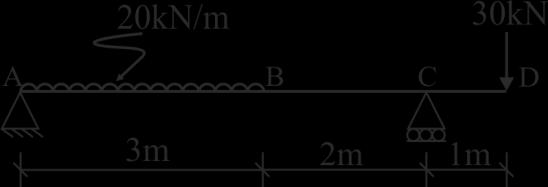

63 Figures FIG.1.. FIG.2 FIG.3.. FIG.4 FIG.5.. FIG.6 FIG.7. ************* 3
64 Seat No.: Enrolment No. GUJARAT TECHNOLOGICAL UNIVERSITY B.E. SEMESTER III (NEW) EXAMINATION SUMMER 2015 Subject Code: Date:11/06/2015 Subject Name: Mechanics of Solids Time: 02.30pm-05.00pm Total Marks: 70 Instructions: 1. Attempt all questions. 2. Make suitable assumptions wherever necessary. 3. Figures to the right indicate full marks. Q.1 (a) Explain following terms (i) Rigid body, (ii) Deformable body (iii) Elastic body 03 (b) State Hooks Law. Derive formula to determine change in length (δl) for the uniform, homogeneous axially loaded member of length (L), c/s area (A) and modulus of elasticity (E), subjected to axial tensile force (P). 04 (c) A stepped circular bar ABC is axially loaded as shown in fig. (i), is in equilibrium. The diameter of part AB is 50 mm throughout its length, whereas diameter part BC is uniform decreasing from 40 mm at B to 30 mm at C. Determine (i) magnitude of unknown force P (ii) stress in part AB and (iii) change in length of part BC. Take modulus of elasticity = 2 x 10 5 N/mm 2. Q.2 (a) Derive relation between Rate of loading, Shear force and Bending moment at a section in a beam subjected to general loading. Also derive condition for maximum BM in terms of SF. (b) Find magnitude and inclination with +X-axis of resultant of force system shown in fig (ii). Identify type of force system. OR (b) A cylindrical roller weighing 1000 N is resting between two smooth surfaces inclined at 60º and 30º with horizontal as shown in fig. (iii). Draw free body diagram and determine reactions at contact points A and B. Q.3 (a) Calculate shear force and bending moment at salient points for the beam shown in fig. (iv). Also plot neat shear force and bending moment diagrams indicating values at above points. Locate point of contraflexure from support B. (b) A reinforced concrete column 500 mm x 500 mm in section is reinforced with four steel bars of 25 mm diameter, one in each corner. The column is carrying an axial load of 1000 kn. Find the stresses in concrete and steel bars. Take E for steel = 210 GPa and E for concrete = 14 GPa. OR Q.3 (a) Explain (i) Angle of limiting friction (ϕ lim ), (ii) Angle of repose (λ), and (iii) Coefficient of friction (μ). Also prove that ϕ lim and λ are numerically same. (b) Determine the location of centroid of plane lamina shown in fig. (v) with respect to point O. Q.4 (a) Two blocks are connected by a horizontal link AB are supported on two rough planes as shown in fig. (vi). The coefficient of friction for block A is 0.4 and angle of friction for block B is ϕ = 15º What is the smallest weight W A of the block A for which the equilibrium of the system can exist? (b) State Parallel axis theorem and perpendicular axis theorem. Derive formula for moment of Inertia of a rectangular section about horizontal centroidal axis from first fundamental. Using parallel axis theorem derive formula for moment of inertia about base of the section. OR 1
65 Q.4 (a) A steel circular bar of 16 mm diameter is placed inside a copper tube, having internal diameter of 20 mm and thickness of 2.5 mm as shown in fig. (vii). Both the ends are rigidly fixed and initially stress free. If the temperature of assembly is increased by 50ºC, compute magnitude and nature of stresses produced in each material. Take modulus of elasticity of steel and copper as 200 GPa and 100 GPa respectively. Take coefficient of thermal expansion (per ºC) for steel and copper as 12 x 10-6 and 18 x 10-6 respectively. (b) A rectangular block is 205 mm long, 100 mm wide and 80 mm thick. It is subjected to a tensile load of 200 kn, compressive load of 300 kn and tensile load of 250 kn along its length, width and thickness respectively. Find the change in volume of the block. Also calculate shear modulus for the block material. Take E = 210 GPa and poison s ratio μ = 0.25 Q.5 (a) Draw bending stress distribution diagram across the cross section of a T beam, having flange 150 x 20 mm and web 20 x 250 mm, carrying pure hogging bending moment of 30 knm at the section. (b) Write the assumptions for finding out shear stress in a circular shaft, subjected to torsion. Prove that τ/r = Cθ/L with usual notations for circular shaft. OR Q.5 (a) Draw shear stress distribution diagram across the cross section of a T beam, having flange 150 x 20 mm and web 20 x 250 mm, carrying pure shear force of 50 kn at the section. (b) A machine component is subjected to the stresses as shown in fig. (viii). Find the normal and shearing stresses on the section AB inclined at an angle of 60º with horizontal (x-x axis). Also find the resultant stress on the section. 40kN A A P kn 4 m B 400 mm 600 mm 16 kn/m Steel bar Fig. (i) Q.1(c) D 2 m Fig.(iv) Q.3(a) Copper tube mm 20mm C 60kN -X 16 kn B C 1 m mm 75 kn +Y 20º O 40 60º 30º 50 kn +X 25 kn 100 kn -Y Fig.(ii) Q.2(b) Y 300mm 2.5 mm Longitudinal Section Cross Section Fig. (vii) Q.4(a) OR O 400mm 100 MPa 150mm Fig.(v) Q.3(b) OR A A 60 B 30 Fig.(iii) Q.2(b) OR W A =? A 30º W B = 400 N B X Fig.(vi) Q.4(a) 50 MPa τ= 25 MPa 60º τ= 25 MPa B 50 MPa Fig. (viii) Q.5(b) OR 100 MPa 2
66 Seat No.: Enrolment No. GUJARAT TECHNOLOGICAL UNIVERSITY BE - SEMESTER 1 st / 2 nd EXAMINATION SUMMER 2014 Subject Code: Date: Subject Name: Mechanics of Solids Time: 02:30 pm - 05:30 pm Total Marks: 70 Instructions: 1. Attempt any five questions. 2. Make suitable assumptions wherever necessary. 3. Figures to the right indicate full marks. Q.1 (a) Fill in the blanks with the most appropriate answer. Write complete sentence with the answer. 1) Three coplanar non-parallel forces in equilibrium will be concurrent. [always, never, sometimes] 2) A M.S. bar under tension test shows the property of. [malleability, ductility, tension ability] 3) Which one of the expression is not true. [E=2G(1+µ ), E=3K(1-2µ ),E=9KG/(3G+K),M= I/Y ] 4) Point of contraflexture is where.[shear force is zero, shear force changes sign, B.M.is zero, B.M. changes sign] 5) The shape of shear force diagram for cantilever beam subjected to couple at free end is. [horizontal straight line, zero, parabola, hexagonal] 6) All joints in a truss are joints.[pin, fixed, rigid] 7) On oiling the lifting machine is NOT affected. [velocity ratio, mechanical advantage, efficiency, law of machine] (b) Define Hardness, Toughness, Equilibrant, Poisson s ratio, Perfect truss, Bulk modulus of elasticity and Particle. Q.2 (a) Determine the resultant of the forces acting on the board as shown in figure (b) The extremities A & D of a light inextensible string ABCD are tied to two points in the same horizontal line. Weight W &3W are tied to the string at the points B &C resp. of AB&CD are inclined to the vertical at angles 60 o & 30 o resp.show that BC is horizontal & find the tensions in the various parts of the string as shown in figure Q.3 A beam is loaded as shown in figure 3 1) Determine the reactions at supports 2) Draw S.F diagram for the beam 03 3) Draw B.M diagram for the beam & determine the magnitude of maximum B.M. 04 Q.4 A section of beam as shown in figure 4 is subjected to a B.M of 10 KN m about the major axis & A S.F of 20KN. 1) Determine the M.I. of the section about both the centroid axis. 2) Draw bending stress distribution across the section. 03 3) Draw shear stress distribution across the section 04 1
67 Q.5 A truss is loaded as shown in figure 5. Determine 1) The support reactions 06 2) Internal forces in the members. 08 Q.6 (a) A 5m long ladder & 250N weight is placed against a vertical wall in a position where it s inclination to the vertical is 30 o. A man weighing 800N climbs the ladder. At what position will he induce slipping? The coefficient of friction between floor & ladder is 0.2 & that between vertical wall & ladder is also 0.2. (b) For an element as shown in figure 6. Find 1) Principal stresses & location of corresponding principal planes 2) Maximum shear stress & location of planes containing it. Q.7 (a) The V.R of the lifting machine is 50. By this machine to lift a load of 4000N an effort of 100N is required.find (a) MA, (b)ή of M/C, (c) is the M/C reversible or self locking and (d) if reversible, what maximum effort should be applied to prevent reversal of motion. (b) A rectangular block of material is 250 mm long, 100mm wide and 80mm thick. If it is subjected to a tensile load of 200kN, compressive load of 300kN and tensile load of 250kN along its length, width and thickness respectively. Find the change in volume of the block. Take E= 210GPa and Poisson s ratio µ=
68 ************* 3
69 Seat No.: Enrolment No. GUJARAT TECHNOLOGICAL UNIVERSITY B.E. SEMESTER III EXAMINATION WINTER 2014 Subject Code: Date: 26/12/2014 Subject Name: Mechanics of Solids Time: 02.30p.m p.m. Total Marks: 70 Instructions: 1. Attempt all questions. 2. Make suitable assumptions wherever necessary. 3. Figures to the right indicate full marks. 4. Draw neat and clean sketches, wherever required. Q.1 (a) Enumerate various types of supports with neat symbolic sketches, showing possible reactions. (b) Define (i) Poisson s ratio (ii) Volumetric Strain (iii) Modulus of rigidity (iv) Bulk modulus (c) A cast iron water pipe of 500 mm inside diameter and 20 mm thick, is supported over a span of 10 meters. Find the maximum bending stress in the pipe metal, when the pipe is running full. Take density of cast iron = 70.6 kn/m 3 and water = 9.8 kn/m 3. Q.2 (a) State Law of parallelogram of forces. Determine magnitude and direction of the resultant of the two forces shown in fig. (i) (b) State pappus Guldinus theorems. Using these theorems derive the formula for surface area (A) and volume (V) for sphere of radius r. OR (b) Derive relation between the rate of loading, shear force and bending moment with usual notations. Q.3 (a) A stepped circular bar ABCD is axially loaded as shown in fig. (ii) is in equilibrium. Find unknown force P, and calculate stresses in each part and total change in length of the bar. Take E copper = 100 GPa, E brass = 80 GPa and E steel = 200 GPa. (b) For an element shown in fig. (iii), find (i) principal stresses and location of corresponding principal planes (ii) Maximum shear stress and location of planes containing it. OR Q.3 (a) Determine the resultant of the forces 100 N, 200 N, 300 N, 400 N and 500 N are acting on one of the vertex of a regular hexagon, towards the other vertices, taken in order as shown in fig. (iv). (b) A ladder AB is 4.5 m long and 450 N weight, rests on a rough horizontal floor at end B and vertical wall at A, making 60º with horizontal. The coefficient of static friction is 0.4 for all contact surfaces. A man of 800 N weight climbs on the ladder. Determine the minimum distance travelled on the ladder, when it is on the verge of slipping. Q.4 (a) A beam is loaded as shown in fig. (v). Calculate shear force and bending moment at points A, B, C, D and E and draw shear force and bending moment diagrams. Also find point of contraflexure. (b) A short concrete column 450mm x 450mm in section is axially loaded to 500 kn. The column is strengthened by four, 16mm diameter steel bars each one at corner. Calculate stresses in concrete and steel. Take Ec = 14 GPa and Es = 210 Gpa OR Q.4 (a) A T shaped cross section of a beam has flange = 200 x 50 mm and web = 50 x 200 mm in size, is subjected to a vertical shear force of 100 kn. Calculate the
70 shear stresses at important points and draw shear stress distribution diagram. Take moment of inertia about horizontal neutral axis = x 10 6 mm 4. (b) Determine moment of inertia about horizontal centroidal axis for the section shown in fig. (vi) Q.5 (a) State conditions of equilibrium for coplanar and concurrent forces. 03 (b) State and explain varignon s theorem, using illustrative example. 04 (c) In an assembly of steel rod of 20 mm diameter passes centrally through a copper tube 40 mm external diameter and 30 mm internal diameter. The tube is closed at both ends by rigid plates of negligible thickness, is initially stress free. If the temperature of the assembly is raised by 60 C, calculate stresses developed in copper and steel. Take Modulus of elasticity E for steel = 200 MPa and for copper = 100 MPa, Co efficient of thermal expansion for steel = 12 x 10-6 / C and for copper = 18 x 10-6 / C. OR Q.5 (a) State laws of dry friction. 03 (b) Define couple and discuss its characteristics. 04 (c) A solid steel circular shaft is required to transmit a torque of 6.5 knm. Determine minimum diameter of the shaft, if shear stress is limited to 40 N/mm 2 and angle of twist should not exceed 0.5º per meter. Take Modulus of rigidity C = 85 GPa. A 30 ************* 20kN C STEEL A COPPER B BRASS 30 kn 16 mm φ 50 kn 12 mm φ 60 kn 24 mm φ D P kn m 1.0 m 1.2 m 50kN Fig. (i) Q.2(a) 150 N/mm 2 τ=100 N/mm 2 100N Fig. (ii) Q.3(a) 200N 300N C D 400 N/mm N/mm 2 B E 400N τ=100 N/mm N/mm 2 Fig. (iii) Q.3(b) A 500N F Fig. (iv) Q.3(a) OR Y 40 kn 80 kn 20kN/m 40 knm A B C D E 3 m 2m 2m 2m Fig. (v) Q.4(a) 200mm 150mm 150mm 150mm 150mm Fig. (vi) Q.4(b) OR 100mm hole X 2
71 Seat No.: Enrolment No. GUJARAT TECHNOLOGICAL UNIVERSITY BE - SEMESTER 1 st / 2 nd EXAMINATION SUMMER 2013 Subject Code: Date: Subject Name: Mechanics of Solids Time: 02:30 pm 05:00 pm Total Marks: 70 Instructions: 1. Attempt any five questions. 2. Make suitable assumptions wherever necessary. 3. Figures to the right indicate full marks. Q.1 (a) Define: (i) Space (ii) Particle (iii) Equilibrant 03 (b) Locate the centroid of composite line ABCD as shown in figure (c) A cord supported at A and B carries a load of 20kN at D and a load of W at C as shown in figure 2. Find the value of W so that CD remains horizontal. Q.2 (a) State: (i) Law of Parallelogram of Forces (ii) Law of Triangle of Forces 03 (b) A wooden beam 2m long, simply supported at ends, has rectangular section mm 600mm and carries a point load of 20kN at center of the beam. Calculate the bending stress at a layer 200mm above the bottom of the beam, the layer being of the section distant 0.8m from left support. (c) Find forces in members CD, FG and FD. The truss is shown in figure 3. Q.3 (a) Enlist various type of loads and type of supports. 03 (b) A beam of rectangular section 100mm 300mm is subjected to a shear 04 force of 10kN. Find shear stress at the top layer, at neutral layer and the average value of shear stress. Show the stress distribution diagram. (c) Some forces are acting on a rigid body as shown in figure 4. Find the resultant of the given force system, in terms of magnitude and direction. Find the location of the Resultant with respect to point O. Q.4 (a) Distinguish between perfect, unstable and redundant trusses. Illustrate with 03 sketches. (b) Find reaction at support A and B for the beam shown in figure (c) Calculate shear force and bending moment at salient points of the beam shown in figure 6. Draw shear force diagram and bending moment diagram for the beam. Q.5 (a) State Pappus-Guldinus first theorem and prove it. 03 (b) A force is acting at an angle of 45 o. Find the components along the axes 04 m-m and n-n as shown in figure 7. (c) Find the moment of inertia of the area about x-x axis as shown in figure 8. Q.6 (a) Define: (i) Coefficient of friction (ii) Angle of friction (iii) Stress 03 (b) Refer figure 9. The coefficient of frictions between the block and the 04 inclined plane is 0.2. Determine the least value of the force P required just to move the block up along the inclined plane. (c) A steel rod of 30mm diameter is placed inside a copper tube of external diameter 50mm and internal diameter 40mm, having length equal to 500mm and connected rigidly at the ends as shown in figure 10. The bar is subjected to axial pull of 150kN. Find the stresses in each material and elongation of the composite bar. Take E steel = 200 GPa and E copper = 100GPa. Q.7 (a) A uniform ladder of weight 250N and length 5m is placed against a vertical wall in a position where its inclination to the vertical is 30 o. A person weighing 700N climbs the ladder. At what position of the person the ladder 1/2
72 will start to slip? Take coefficient of friction μ = 0.2 at both the contact surfaces of the ladder. (b) For the state of stress as shown in figure 11 determine location of principal planes, principal stresses and maximum shear stress. ************* y B x A 4m 45 o C x A 60 o 30 o B D D C y W 20kN Fig. 1 [Q-1(b)] Fig. 2 [Q-1(c)] 20kN 20kN F 10kN G 10kN 30N 30 o (90, 60) 10N E H 45 o O A 45 o 45 o 45 o 45 o 20Nm C D B 3 3m 3m ( 100, 60) Coordinates are in mm Fig. 3 [Q-2(c)] Fig. 4 [Q-3(c)] A 30kN 20kNm 10kN/m 10k 20kN/ B C D 1.5m 1.5m 3.0m A B C 2 2 Fig. 5 [Q-4(b)] Fig. 6 [Q-4(c)] 4 P n 25kN 20 o Block 2m 120 o 45 o 5k m m x o x n 2m 6 30 o Fig. 7 [Q-5(b)] Fig. 8 [Q-5(c)] Fig. 9 [Q-6(b)] 20MPa 30MPa 150kN 30ф steel rod 500mm Fig. 10 [Q-6(c)] 150kN 40ф 50ф 40MPa 20MPa Fig. 11 [Q-7(b)] 60MPa 30MPa 2/2
73 Seat No.: Enrolment No. GUJARAT TECHNOLOGICAL UNIVERSITY BE - SEMESTER 1 st / 2 nd EXAMINATION WINTER 2013 Subject Code: Date: Subject Name: Mechanics of Solids Time: 10:30 am 01:00 pm Total Marks: 70 Instructions: 1. Attempt any five questions. 2. Make suitable assumptions wherever necessary. 3. Figures to the right indicate full marks. Q.1 (a) Fill in the blanks with most appropriate word/words. 1. Beam extends beyond the support then that beam is known as beam. 2. Moment of inertia of any plane area is maximum about an axis passing though. 3. Every joint of plane truss is having force system and system of forces is in equilibrium. 4. Deficient truss has members (N) (2j-3) 5. At free end of a cantilever bending moment is always unless a concentrated moment is applied at the free end. 6. of a force is the procedure of splitting a force into number of components. 7. is equal and opposite to the resultant of several forces, acting on a body. 8. Force of friction is to the applied force, which tends to move the body. (b) A steel member ABCD with three different circular cross-section and lengths as follows, is subjected to an axial pull of 150kN. Compute the net change in the length of the member if the modulus of elasticity (E)=200GPa. AB: diameter=40mm and length=750mm BC: diameter=25mm and length=1000mm CD: diameter=30mm and length=1200mm Q.2 (a) The following forces are acting at a point, find the magnitude and direction of the resultant force N acting towards North N acting at 40 towards South of West kn acting at 60 towards South of East N acting from West to East (b) A cement concrete block having a shape of square cross section of 250mm side and a uniform height of 350mm is tested in a compression testing machine by applying an axial compressive load of P. It was observed that the height decreased by 0.28mm and the side increased by 0.035mm. If the Modulus of Elasticity of concrete is 0.13x10 5 N/mm 2, determine Poison s Ratio The value of P
74 (c) The volumetric strain of the block. A steel rail is 10m long and is laid at a temperature of 20 C. The maximum temperature expected is 50 C, estimate the minimum gap between two rails to be left so that temperature stresses do not developed. The coefficient of linear expansion α steel =12x10-6 per C per unit length. 03 Q.3 (a) Determine support reactions for the beam loaded as shown in fig.1. (b) Find the angle of tilt Ɵ with horizontal so that the contact force (Reaction) at B will be one-half at A for a smooth cylinder of weight 100N. Refer fig.2. Q.4 (a) Determine the resultant and locate the same with respect to point A of a non-concurrent force system shown in fig.3. (b) Find out forces in all the members of a truss shown in fig.4. Q.5 (a) Determine the centroid of the shaded area shown in fig.5. Also calculate the volume of the article generated by revolving the area about vertical axis AB. (b) Calculate the Moment of inertia of the shaded area shown in fig.5 about the vertical axis AB. Q. 6 (a) Draw Shear force and bending moment diagrams showing all necessary calculations for the beam loaded as show in fig.6. (b) A uniform ladder, of length 5m, is supported by a horizontal floor at A and a vertical wall at B and makes an angle of 60 with the horizontal. Find the maximum distance x up the ladder at which a man of weight 700N can stand without causing slipping of the ladder. The coefficient of friction between floor & ladder and wall & ladder is 0.3. Neglect the weight of ladder. Q.7 (a) Determine maximum bending stress and maximum shear stress in a cantilever beam of length 2m. The beam carries a udl of 8kN/m over the entire length of 2m and a concentrated vertical downward load of 25kN at the free end of cantilever. The cross-section of the beam is a rectangle of size 350mm deep and 250mm wide. (b) The state of stress in two-dimensionally stressed body at a point is as shown in fig.7. Determine the principal stresses and maximum shear stress ***************
75 SKETCHES 60kN 80kN.m 30kN/m 20kN 0.8m A B 0.5m 1.5m 1.5m 3m Fig.1 (Q:3(a)) B A Ɵ Fig.2 (Q:3(b)) 1.1kN 500N A kN 4.0kN.m 1.5m 45 2m 1200N Fig.3(Q:4(a)) A 300kN C α Ɵ 2m E 4m 300kN D 5m B 2m Fig.4(Q:4(b)) A 85N/mm 2 1m 1m R=2m 60N/mm 2 110N/mm 2 110N/mm 2 60N/mm 2 B Fig.5(Q:5(a)&(b)) 85N/mm 2 Fig.7(Q:7(b)) 30kN 50kN 30kN 20kN/m A 2m C 2m D 2m E 2m B Fig.6(Q:6(a))
76 MOS (SHORT QUESTIONS) Short Questions Sr No Question Answer 1 Three coplanar non-parallel forces in equilibrium will [always, never, Sometimes sometimes] be concurrent kg = [10 3, 10-6,10 9, 10-3 ] Mg Coefficient of static fiction is [less than, more than, Equal to] coefficient of dynamics fiction. 4 A mild steel bar under tension test shows property of [Malleability, ductility, tension ability]. 5 The shape of shear force diagram for cantilever beam subjected to couple at free end is [horizontal straight line, zero, Parabola, incline straight line]. 6 The ratio of the maximum shear stress to average shear stress is for 4/3, the cross section would be [triangular, rectangular, Circular, hexagonal]. 7 Which one of expressions is NOT true [E = 2G (1+µ), E = 3K (1-2µ), E = 9KG/ (3G+K), M = s. I/y]. 8 Point of contra flexure is where [shear force is zero, shear force changes sign, bending moment changing sign, bending Moment is zero]. 9 Lateral strains are longitudinal strains. (always less than, sometimes less than, never less than) More than Ductility zero Circular E = 9KG/ (3G+K) Bending moment changes its sign Less than 10 Two forces under equilibrium must be ( non rectilinear, rectilinear, parallel) rectilinear 11 True relation between dynamic coefficient of friction ( µd) and static coefficient of friction (µs) is (µd < µs, µd = µs, µd > µs) µd < µs 12 is a scalar quantity.( momentum, force, work) Work mm µm ( 10 5, 10 6, 10-7 ) Beam extends beyond the support then that beam is known As beam. Overhanging beam 15 Moment of inertia of any plane area is maximum about an axis Passing though. 16 At free end of a cantilever bending moment is always unless a concentrated moment is applied at the free end. 17 of a force is the procedure of splitting a force into number of components 18 is equal and opposite to the resultant of several Forces, acting on a body. Centre of gravity Zero Resolution Reaction 19 Force of friction is to the applied force, which tends to move the body. Opposite 20 Splitting of force in given directions is known as of force. (resolution, composition, division) 21 Poisson s ratio is ratio of (longitudinal to lateral strain, lateral to longitudinal strain, shear stress to shear strain) resolution Lateral to longitudinal 22 Bending moment is at a hinged support. (always maximum, always zero) Always zero 23 Force can be defined in term of its,, and point of [. magnitude, direction, point of application 24 Inertia is the resistance of body to any change in its [ Velocity 25 Solid of mechanics comprises study of mechanics of bodies and mechanics of deformable bodies 26 The process of replacing a set of forces by a single force is called of force Composition 27 A sketch showing a body in equilibrium along with all the forces acting on it, is called a [] rigid Free body diagram Darshan Institute of Engineering & Technology


77 MOS (SHORT QUESTIONS) 28 Two unlike and parallel forces, will form a Couple 29 Hinge support cannot prevent any of the body that they support. Rotation 30 Centre of gravity is defined as the point on which the of the body acts. weight 31 The centroid is the of a homogeneous object. [ geometrical center 32 A cylinder is a surface of revolution generated by revolving a about a fixed axis 33 Radius of gyration is given by the equation KX = 34 Friction the efficiency of a machine and the work required to be done 35 Dry friction occurs when unlubricated surfaces are in contact under condition of. Straight line reduces, increase Sliding 36 Fluid friction occurred between of fluids at different [ layers, velocity 37 At a point when motion is about to begin, the frictional force has reached its value 38 Frictional force will always be in a direction to that in which the body tends to move] limiting Opposite 39 The ration of shear stress to shear strain is known as. [ Modulus of rigidity 40 Poisson s ratio for most of the materials is close to Young s modulus of elasticity for a perfectly rigid body is. Infinity 42 A metal bar is heated without any restrain, the temperature stress will be. Zero 43 Diagonal tensile and compressive stresses in the member are the result of force. 44 Deformation of the statically indeterminate structures can be obtained by using condition and condition. Shear equilibrium, capability 45 Lateral strains are longitudinal strains. always less than 46 A support is an example of a support with an unknown line of action. Hinge 47 The stress in the beam is lesser if its section modulus is. higher 48 Moment of resistance of the flanges of an I- section is its web higher than 49 IF arm of couple is doubled. Its moment will - Be doubled 50 In a Cantilever, carrying a load whose intensity varies uniformly from zero at the free end to w per unit run at the fixed end, the SF diagram changes following a Parabolic law 51 A body is said to be in equilibrium if it has no linear motion [true, false] False 52 If arm of couple is doubled its moment will Be doubled 53 If a ladder is not in equilibrium against a smooth vertical wall, than it can be made in equilibrium by Increasing angle of inclination with horizontal 54 Ductility is the ability of a material to be drawn in the form of a Wires 55 Statically determinate structures can be analyzed using the 3 equation of Static equilibrium 56 The relationship between shear force and bending moment is given by the differential Equation (δm/δx)= -F Darshan Institute of Engineering & Technology
SN QUESTION YEAR MARK 1. State and prove the relationship between shearing stress and rate of change of bending moment at a section in a loaded beam.
 ALPHA COLLEGE OF ENGINEERING AND TECHNOLOGY DEPARTMENT OF MECHANICAL ENGINEERING MECHANICS OF SOLIDS (21000) ASSIGNMENT 1 SIMPLE STRESSES AND STRAINS SN QUESTION YEAR MARK 1 State and prove the relationship
A. Objective of the Course: Objectives of introducing this subject at second year level in civil branches are: 1. Introduction 02
 Subject Code: 0CL030 Subject Name: Mechanics of Solids B.Tech. II Year (Sem-3) Mechanical & Automobile Engineering Teaching Credits Examination Marks Scheme Theory Marks Practical Marks Total L 4 T 0 P
Semester: BE 3 rd Subject :Mechanics of Solids ( ) Year: Faculty: Mr. Rohan S. Kariya. Tutorial 1
 Year: Faculty: Mr. Rohan S. Kariya. Tutorial 1") Semester: BE 3 rd Subject :Mechanics of Solids (2130003) Year: 2018-19 Faculty: Mr. Rohan S. Kariya Class: MA Tutorial 1 1 Define force and explain different type of force system with figures. 2 Explain
Semester: BE 3 rd Subject :Mechanics of Solids (2130003) Year: 2018-19 Faculty: Mr. Rohan S. Kariya Class: MA Tutorial 1 1 Define force and explain different type of force system with figures. 2 Explain
MECHANICS OF SOLIDS Credit Hours: 6
 MECHANICS OF SOLIDS Credit Hours: 6 Teaching Scheme Theory Tutorials Practical Total Credit Hours/week 4 0 6 6 Marks 00 0 50 50 6 A. Objective of the Course: Objectives of introducing this subject at second
MARKS DISTRIBUTION AS PER CHAPTER (QUESTION ASKED IN GTU EXAM) Name Of Chapter. Applications of. Friction. Centroid & Moment.
 Name Of Chapter. Applications of. Friction. Centroid & Moment.") Introduction Fundamentals of statics Applications of fundamentals of statics Friction Centroid & Moment of inertia Simple Stresses & Strain Stresses in Beam Torsion Principle Stresses DEPARTMENT OF CIVIL
Introduction Fundamentals of statics Applications of fundamentals of statics Friction Centroid & Moment of inertia Simple Stresses & Strain Stresses in Beam Torsion Principle Stresses DEPARTMENT OF CIVIL
PDDC 1 st Semester Civil Engineering Department Assignments of Mechanics of Solids [ ] Introduction, Fundamentals of Statics
![PDDC 1 st Semester Civil Engineering Department Assignments of Mechanics of Solids [ ] Introduction, Fundamentals of Statics](/thumbs/92/109382806.jpg "PDDC 1 st Semester Civil Engineering Department Assignments of Mechanics of Solids [ ] Introduction, Fundamentals of Statics") Page1 PDDC 1 st Semester Civil Engineering Department Assignments of Mechanics of Solids [2910601] Introduction, Fundamentals of Statics 1. Differentiate between Scalar and Vector quantity. Write S.I.
Page1 PDDC 1 st Semester Civil Engineering Department Assignments of Mechanics of Solids [2910601] Introduction, Fundamentals of Statics 1. Differentiate between Scalar and Vector quantity. Write S.I.
BE Semester- I ( ) Question Bank (MECHANICS OF SOLIDS)
 Question Bank (MECHANICS OF SOLIDS)") BE Semester- I ( ) Question Bank (MECHANICS OF SOLIDS) All questions carry equal marks(10 marks) Q.1 (a) Write the SI units of following quantities and also mention whether it is scalar or vector: (i)
BE Semester- I ( ) Question Bank (MECHANICS OF SOLIDS) All questions carry equal marks(10 marks) Q.1 (a) Write the SI units of following quantities and also mention whether it is scalar or vector: (i)
VALLIAMMAI ENGINEERING COLLEGE SRM NAGAR, KATTANKULATHUR DEPARTMENT OF MECHANICAL ENGINEERING
 VALLIAMMAI ENGINEERING COLLEGE SRM NAGAR, KATTANKULATHUR 603203 DEPARTMENT OF MECHANICAL ENGINEERING BRANCH: MECHANICAL YEAR / SEMESTER: I / II UNIT 1 PART- A 1. State Newton's three laws of motion? 2.
KINGS COLLEGE OF ENGINEERING ENGINEERING MECHANICS QUESTION BANK UNIT I - PART-A
 KINGS COLLEGE OF ENGINEERING ENGINEERING MECHANICS QUESTION BANK Sub. Code: CE1151 Sub. Name: Engg. Mechanics UNIT I - PART-A Sem / Year II / I 1.Distinguish the following system of forces with a suitable
Sub. Code:
 Important Instructions to examiners: ) The answers should be examined by key words and not as word-to-word as given in the model answer scheme. ) The model answer and the answer written by candidate may
QUESTION BANK SEMESTER: III SUBJECT NAME: MECHANICS OF SOLIDS
 QUESTION BANK SEMESTER: III SUBJECT NAME: MECHANICS OF SOLIDS UNIT 1- STRESS AND STRAIN PART A (2 Marks) 1. Define longitudinal strain and lateral strain. 2. State Hooke s law. 3. Define modular ratio,
QUESTION BANK DEPARTMENT: CIVIL SEMESTER: III SUBJECT CODE: CE2201 SUBJECT NAME: MECHANICS OF SOLIDS UNIT 1- STRESS AND STRAIN PART A
 DEPARTMENT: CIVIL SUBJECT CODE: CE2201 QUESTION BANK SEMESTER: III SUBJECT NAME: MECHANICS OF SOLIDS UNIT 1- STRESS AND STRAIN PART A (2 Marks) 1. Define longitudinal strain and lateral strain. 2. State
2014 MECHANICS OF MATERIALS
 R10 SET - 1 II. Tech I Semester Regular Examinations, March 2014 MEHNIS OF MTERILS (ivil Engineering) Time: 3 hours Max. Marks: 75 nswer any FIVE Questions ll Questions carry Equal Marks ~~~~~~~~~~~~~~~~~~~~~~~~~
PERIYAR CENTENARY POLYTECHNIC COLLEGE PERIYAR NAGAR - VALLAM THANJAVUR. DEPARTMENT OF MECHANICAL ENGINEERING QUESTION BANK
 PERIYAR CENTENARY POLYTECHNIC COLLEGE PERIYAR NAGAR - VALLAM - 613 403 - THANJAVUR. DEPARTMENT OF MECHANICAL ENGINEERING QUESTION BANK Sub : Strength of Materials Year / Sem: II / III Sub Code : MEB 310
where G is called the universal gravitational constant.
 UNIT-I BASICS & STATICS OF PARTICLES 1. What are the different laws of mechanics? First law: A body does not change its state of motion unless acted upon by a force or Every object in a state of uniform
Dept of ECE, SCMS Cochin
 B B2B109 Pages: 3 Reg. No. Name: APJ ABDUL KALAM TECHNOLOGICAL UNIVERSITY SECOND SEMESTER B.TECH DEGREE EXAMINATION, MAY 2017 Course Code: BE 100 Course Name: ENGINEERING MECHANICS Max. Marks: 100 Duration:
2. a) Explain the equilibrium of i) Concurrent force system, and ii) General force system.
 Explain the equilibrium of i) Concurrent force system, and ii) General force system.") Code No: R21031 R10 SET - 1 II B. Tech I Semester Supplementary Examinations Dec 2013 ENGINEERING MECHANICS (Com to ME, AE, AME, MM) Time: 3 hours Max. Marks: 75 Answer any FIVE Questions All Questions
Code No: R21031 R10 SET - 1 II B. Tech I Semester Supplementary Examinations Dec 2013 ENGINEERING MECHANICS (Com to ME, AE, AME, MM) Time: 3 hours Max. Marks: 75 Answer any FIVE Questions All Questions
Bachelor of Technology Civil Engineering. 01CI0301: Mechanics of Solids
 01CI0301: Mechanics of Solids Objective of the Course Objectives of introducing this subject at second year level in civil branches are: To study about identification of different types of forces, systematic
Questions from all units
 Questions from all units S.NO 1. 1 UNT NO QUESTON Explain the concept of force and its characteristics. BLOOMS LEVEL LEVEL 2. 2 Explain different types of force systems with examples. Determine the magnitude
Bachelor of Technology Civil Engineering. 01CI0301: Mechanics of Solids
 01CI0301: Mechanics of Solids Objective of the Course Objectives of introducing this subject at second year level in civil branches are: To study about identification of different types of forces, systematic
JNTU World. Subject Code: R13110/R13
 Set No - 1 I B. Tech I Semester Regular Examinations Feb./Mar. - 2014 ENGINEERING MECHANICS (Common to CE, ME, CSE, PCE, IT, Chem E, Aero E, AME, Min E, PE, Metal E) Time: 3 hours Max. Marks: 70 Question
UNIT-I STRESS, STRAIN. 1. A Member A B C D is subjected to loading as shown in fig determine the total elongation. Take E= 2 x10 5 N/mm 2
 UNIT-I STRESS, STRAIN 1. A Member A B C D is subjected to loading as shown in fig determine the total elongation. Take E= 2 x10 5 N/mm 2 Young s modulus E= 2 x10 5 N/mm 2 Area1=900mm 2 Area2=400mm 2 Area3=625mm
18.Define the term modulus of resilience. May/June Define Principal Stress. 20. Define Hydrostatic Pressure.
 CE6306 STREGNTH OF MATERIALS Question Bank Unit-I STRESS, STRAIN, DEFORMATION OF SOLIDS PART-A 1. Define Poison s Ratio May/June 2009 2. What is thermal stress? May/June 2009 3. Estimate the load carried
PART-A. a. 60 N b. -60 N. c. 30 N d. 120 N. b. How you can get direction of Resultant R when number of forces acting on a particle in plane.
 V.S.. ENGINEERING OLLEGE, KRUR EPRTMENT OF MEHNIL ENGINEERING EMI YER: 2009-2010 (EVEN SEMESTER) ENGINEERING MEHNIS (MEH II SEM) QUESTION NK UNIT I PRT- EM QUESTION NK 1. efine Mechanics 2. What is meant
Downloaded from Downloaded from / 1
 PURWANCHAL UNIVERSITY III SEMESTER FINAL EXAMINATION-2002 LEVEL : B. E. (Civil) SUBJECT: BEG256CI, Strength of Material Full Marks: 80 TIME: 03:00 hrs Pass marks: 32 Candidates are required to give their
R13. II B. Tech I Semester Regular Examinations, Jan MECHANICS OF SOLIDS (Com. to ME, AME, AE, MTE) PART-A
 PART-A") SET - 1 II B. Tech I Semester Regular Examinations, Jan - 2015 MECHANICS OF SOLIDS (Com. to ME, AME, AE, MTE) Time: 3 hours Max. Marks: 70 Note: 1. Question Paper consists of two parts (Part-A and Part-B)
SET - 1 II B. Tech I Semester Regular Examinations, Jan - 2015 MECHANICS OF SOLIDS (Com. to ME, AME, AE, MTE) Time: 3 hours Max. Marks: 70 Note: 1. Question Paper consists of two parts (Part-A and Part-B)
Mechanics of Structure
 S.Y. Diploma : Sem. III [CE/CS/CR/CV] Mechanics of Structure Time: Hrs.] Prelim Question Paper Solution [Marks : 70 Q.1(a) Attempt any SIX of the following. [1] Q.1(a) Define moment of Inertia. State MI
Set No - 1 I B. Tech I Semester Regular Examinations Jan./Feb ENGINEERING MECHANICS
 3 Set No - 1 I B. Tech I Semester Regular Examinations Jan./Feb. 2015 ENGINEERING MECHANICS (Common to CE, ME, CSE, PCE, IT, Chem E, Aero E, AME, Min E, PE, Metal E) Time: 3 hours Question Paper Consists
ISBN :
 ISBN : 978-81-909042-4-7 - www.airwalkpublications.com ANNA UNIVERSITY - R2013 GE6253 ENGINEERING MECHANICS UNIT I: BASICS AND STATICS OF PARTICLES 12 Introduction Units and Dimensions Laws of Mechanics
SECOND ENGINEER REG. III/2 APPLIED MECHANICS
 SECOND ENGINEER REG. III/2 APPLIED MECHANICS LIST OF TOPICS Static s Friction Kinematics Dynamics Machines Strength of Materials Hydrostatics Hydrodynamics A STATICS 1 Solves problems involving forces
Sample Question Paper
 Scheme I Sample Question Paper Program Name : Mechanical Engineering Program Group Program Code : AE/ME/PG/PT/FG Semester : Third Course Title : Strength of Materials Marks : 70 Time: 3 Hrs. Instructions:
STRESS, STRAIN AND DEFORMATION OF SOLIDS
 VELAMMAL COLLEGE OF ENGINEERING AND TECHNOLOGY, MADURAI 625009 DEPARTMENT OF CIVIL ENGINEERING CE8301 STRENGTH OF MATERIALS I -------------------------------------------------------------------------------------------------------------------------------
.VALLIAMMAI ENGINEERING COLLEGE
 .VALLIAMMAI ENGINEERING COLLEGE SRM Nagar, Kattankulathur 603 203 DEPARTMENT OF GENERAL ENGINEERING QUESTION BANK II SEMESTER GE 8292- Engineering Mechanics Regulation 2017 Academic Year 2017 18 VALLIAMMAI
Equilibrium & Elasticity
 PHYS 101 Previous Exam Problems CHAPTER 12 Equilibrium & Elasticity Static equilibrium Elasticity 1. A uniform steel bar of length 3.0 m and weight 20 N rests on two supports (A and B) at its ends. A block
Where, m = slope of line = constant c = Intercept on y axis = effort required to start the machine
 (ISO/IEC - 700-005 Certified) Model Answer: Summer 07 Code: 70 Important Instructions to examiners: ) The answers should be examined by key words and not as word-to-word as given in the model answer scheme.
Model Answers Attempt any TEN of the following :
 (ISO/IEC - 70-005 Certified) Model Answer: Winter 7 Sub. Code: 17 Important Instructions to Examiners: 1) The answers should be examined by key words and not as word-to-word as given in the model answer
PES Institute of Technology
 PES Institute of Technology Bangalore south campus, Bangalore-5460100 Department of Mechanical Engineering Faculty name : Madhu M Date: 29/06/2012 SEM : 3 rd A SEC Subject : MECHANICS OF MATERIALS Subject
2016 ENGINEERING MECHANICS
 Set No 1 I B. Tech I Semester Regular Examinations, Dec 2016 ENGINEERING MECHANICS (Com. to AE, AME, BOT, CHEM, CE, EEE, ME, MTE, MM, PCE, PE) Time: 3 hours Max. Marks: 70 Question Paper Consists of Part-A
Code No: R Set No. 1
 Code No: R05010302 Set No. 1 I B.Tech Supplimentary Examinations, February 2008 ENGINEERING MECHANICS ( Common to Mechanical Engineering, Mechatronics, Metallurgy & Material Technology, Production Engineering,
UNIT 1 STRESS STRAIN AND DEFORMATION OF SOLIDS, STATES OF STRESS 1. Define stress. When an external force acts on a body, it undergoes deformation.
 UNIT 1 STRESS STRAIN AND DEFORMATION OF SOLIDS, STATES OF STRESS 1. Define stress. When an external force acts on a body, it undergoes deformation. At the same time the body resists deformation. The magnitude
C7047. PART A Answer all questions, each carries 5 marks.
 7047 Reg No.: Total Pages: 3 Name: Max. Marks: 100 PJ DUL KLM TEHNOLOGIL UNIVERSITY FIRST SEMESTER.TEH DEGREE EXMINTION, DEEMER 2017 ourse ode: E100 ourse Name: ENGINEERING MEHNIS PRT nswer all questions,
D : SOLID MECHANICS. Q. 1 Q. 9 carry one mark each. Q.1 Find the force (in kn) in the member BH of the truss shown.
 in the member BH of the truss shown.") D : SOLID MECHANICS Q. 1 Q. 9 carry one mark each. Q.1 Find the force (in kn) in the member BH of the truss shown. Q.2 Consider the forces of magnitude F acting on the sides of the regular hexagon having
D : SOLID MECHANICS Q. 1 Q. 9 carry one mark each. Q.1 Find the force (in kn) in the member BH of the truss shown. Q.2 Consider the forces of magnitude F acting on the sides of the regular hexagon having
K.GNANASEKARAN. M.E.,M.B.A.,(Ph.D)
") DEPARTMENT OF MECHANICAL ENGG. Engineering Mechanics I YEAR 2th SEMESTER) Two Marks Question Bank UNIT-I Basics and statics of particles 1. Define Engineering Mechanics Engineering Mechanics is defined
DEPARTMENT OF MECHANICAL ENGG. Engineering Mechanics I YEAR 2th SEMESTER) Two Marks Question Bank UNIT-I Basics and statics of particles 1. Define Engineering Mechanics Engineering Mechanics is defined
: APPLIED MECHANICS & STRENGTH OF MATERIALS COURSE CODE : 4021 COURSE CATEGORY : A PERIODS/ WEEK : 5 PERIODS/ SEMESTER : 75 CREDIT : 5 TIME SCHEDULE
 COURSE TITLE : APPLIED MECHANICS & STRENGTH OF MATERIALS COURSE CODE : 4021 COURSE CATEGORY : A PERIODS/ WEEK : 5 PERIODS/ SEMESTER : 75 CREDIT : 5 TIME SCHEDULE MODULE TOPIC PERIODS 1 Simple stresses
CIVIL DEPARTMENT MECHANICS OF STRUCTURES- ASSIGNMENT NO 1. Brach: CE YEAR:
 MECHANICS OF STRUCTURES- ASSIGNMENT NO 1 SEMESTER: V 1) Find the least moment of Inertia about the centroidal axes X-X and Y-Y of an unequal angle section 125 mm 75 mm 10 mm as shown in figure 2) Determine
COURSE TITLE : THEORY OF STRUCTURES -I COURSE CODE : 3013 COURSE CATEGORY : B PERIODS/WEEK : 6 PERIODS/SEMESTER: 90 CREDITS : 6
 COURSE TITLE : THEORY OF STRUCTURES -I COURSE CODE : 0 COURSE CATEGORY : B PERIODS/WEEK : 6 PERIODS/SEMESTER: 90 CREDITS : 6 TIME SCHEDULE Module Topics Period Moment of forces Support reactions Centre
COURSE TITLE : APPLIED MECHANICS & STRENGTH OF MATERIALS COURSE CODE : 4017 COURSE CATEGORY : A PERIODS/WEEK : 6 PERIODS/ SEMESTER : 108 CREDITS : 5
 COURSE TITLE : APPLIED MECHANICS & STRENGTH OF MATERIALS COURSE CODE : 4017 COURSE CATEGORY : A PERIODS/WEEK : 6 PERIODS/ SEMESTER : 108 CREDITS : 5 TIME SCHEDULE MODULE TOPICS PERIODS 1 Simple stresses
ENGINEERING MECHANICS - Question Bank
 E Semester-_IST YEAR (CIVIL, MECH, AUTO, CHEM, RUER, PLASTIC, ENV,TT,AERO) ENGINEERING MECHANICS - Question ank All questions carry equal marks(10 marks) Q.1 Define space,time matter and force, scalar
Reg. No. : Question Paper Code : B.Arch. DEGREE EXAMINATION, APRIL/MAY Second Semester AR 6201 MECHANICS OF STRUCTURES I
 WK 4 Reg. No. : Question Paper Code : 71387 B.Arch. DEGREE EXAMINATION, APRIL/MAY 2017. Second Semester AR 6201 MECHANICS OF STRUCTURES I (Regulations 2013) Time : Three hours Maximum : 100 marks Answer
SRI CHANDRASEKHARENDRA SARASWATHI VISWA MAHAVIDHYALAYA
 SRI CHANDRASEKHARENDRA SARASWATHI VISWA MAHAVIDHYALAYA (Declared as Deemed-to-be University under Section 3 of the UGC Act, 1956, Vide notification No.F.9.9/92-U-3 dated 26 th May 1993 of the Govt. of
Statics deal with the condition of equilibrium of bodies acted upon by forces.
 Mechanics It is defined as that branch of science, which describes and predicts the conditions of rest or motion of bodies under the action of forces. Engineering mechanics applies the principle of mechanics
Reg. No. : Question Paper Code : B.E./B.Tech. DEGREE EXAMINATION, NOVEMBER/DECEMBER Second Semester.
 Ws11 Reg. No. : Question Paper Code : 27275 B.E./B.Tech. DEGREE EXAMINATION, NOVEMBER/DECEMBER 2015. Second Semester Civil Engineering GE 6253 ENGINEERING MECHANICS (Common to all branches except Electrical
ISHIK UNIVERSITY DEPARTMENT OF MECHATRONICS ENGINEERING
 ISHIK UNIVERSITY DEPARTMENT OF MECHATRONICS ENGINEERING QUESTION BANK FOR THE MECHANICS OF MATERIALS-I 1. A rod 150 cm long and of diameter 2.0 cm is subjected to an axial pull of 20 kn. If the modulus
2012 MECHANICS OF SOLIDS
 R10 SET - 1 II B.Tech II Semester, Regular Examinations, April 2012 MECHANICS OF SOLIDS (Com. to ME, AME, MM) Time: 3 hours Max. Marks: 75 Answer any FIVE Questions All Questions carry Equal Marks ~~~~~~~~~~~~~~~~~~~~~~
KINGS COLLEGE OF ENGINEERING DEPARTMENT OF MECHANICAL ENGINEERING QUESTION BANK. Subject code/name: ME2254/STRENGTH OF MATERIALS Year/Sem:II / IV
 KINGS COLLEGE OF ENGINEERING DEPARTMENT OF MECHANICAL ENGINEERING QUESTION BANK Subject code/name: ME2254/STRENGTH OF MATERIALS Year/Sem:II / IV UNIT I STRESS, STRAIN DEFORMATION OF SOLIDS PART A (2 MARKS)
STRENGTH OF MATERIALS-I. Unit-1. Simple stresses and strains
 STRENGTH OF MATERIALS-I Unit-1 Simple stresses and strains 1. What is the Principle of surveying 2. Define Magnetic, True & Arbitrary Meridians. 3. Mention different types of chains 4. Differentiate between
Vidyalanakar F.Y. Diploma : Sem. II [AE/CE/CH/CR/CS/CV/EE/EP/FE/ME/MH/MI/PG/PT/PS] Engineering Mechanics
![Vidyalanakar F.Y. Diploma : Sem. II [AE/CE/CH/CR/CS/CV/EE/EP/FE/ME/MH/MI/PG/PT/PS] Engineering Mechanics](/thumbs/77/74871041.jpg "Vidyalanakar F.Y. Diploma : Sem. II [AE/CE/CH/CR/CS/CV/EE/EP/FE/ME/MH/MI/PG/PT/PS] Engineering Mechanics") Vidyalanakar F.Y. Diploma : Sem. II [AE/CE/CH/CR/CS/CV/EE/EP/FE/ME/MH/MI/PG/PT/PS] Engineering Mechanics Time : 3 Hrs.] Prelim Question Paper Solution [Marks : 100 Q.1 Attempt any TEN of the following
Vidyalanakar F.Y. Diploma : Sem. II [AE/CE/CH/CR/CS/CV/EE/EP/FE/ME/MH/MI/PG/PT/PS] Engineering Mechanics Time : 3 Hrs.] Prelim Question Paper Solution [Marks : 100 Q.1 Attempt any TEN of the following
2015 ENGINEERING MECHANICS
 Set No - 1 I B. Tech I Semester Supplementary Examinations Aug. 2015 ENGINEERING MECHANICS (Common to CE, ME, CSE, PCE, IT, Chem E, Aero E, AME, Min E, PE, Metal E) Time: 3 hours Max. Marks: 70 Question
3 Hours/100 Marks Seat No.
 *17304* 17304 14115 3 Hours/100 Marks Seat No. Instructions : (1) All questions are compulsory. (2) Illustrate your answers with neat sketches wherever necessary. (3) Figures to the right indicate full
MECHANICS OF MATERIALS. Prepared by Engr. John Paul Timola
 MECHANICS OF MATERIALS Prepared by Engr. John Paul Timola Mechanics of materials branch of mechanics that studies the internal effects of stress and strain in a solid body. stress is associated with the
 Subject : Engineering Mechanics Subject Code : 1704 Page No: 1 / 6 ----------------------------- Important Instructions to examiners: 1) The answers should be examined by key words and not as word-to-word
STRESS STRAIN AND DEFORMATION OF SOLIDS, STATES OF STRESS
 1 UNIT I STRESS STRAIN AND DEFORMATION OF SOLIDS, STATES OF STRESS 1. Define: Stress When an external force acts on a body, it undergoes deformation. At the same time the body resists deformation. The
if the initial displacement and velocities are zero each. [ ] PART-B
![if the initial displacement and velocities are zero each. [ ] PART-B](/thumbs/86/94772448.jpg "if the initial displacement and velocities are zero each. [ ] PART-B") Set No - 1 I. Tech II Semester Regular Examinations ugust - 2014 ENGINEERING MECHNICS (Common to ECE, EEE, EIE, io-tech, E Com.E, gri. E) Time: 3 hours Max. Marks: 70 Question Paper Consists of Part- and
Set No - 1 I. Tech II Semester Regular Examinations ugust - 2014 ENGINEERING MECHNICS (Common to ECE, EEE, EIE, io-tech, E Com.E, gri. E) Time: 3 hours Max. Marks: 70 Question Paper Consists of Part- and
Strength of Materials (15CV 32)
") Strength of Materials (15CV 32) Module 1 : Simple Stresses and Strains Dr. H. Ananthan, Professor, VVIET,MYSURU 8/21/2017 Introduction, Definition and concept and of stress and strain. Hooke s law, Stress-Strain
Strength of Materials (15CV 32) Module 1 : Simple Stresses and Strains Dr. H. Ananthan, Professor, VVIET,MYSURU 8/21/2017 Introduction, Definition and concept and of stress and strain. Hooke s law, Stress-Strain
GATE SOLUTIONS E N G I N E E R I N G
 GATE SOLUTIONS C I V I L E N G I N E E R I N G From (1987-018) Office : F-16, (Lower Basement), Katwaria Sarai, New Delhi-110016 Phone : 011-65064 Mobile : 81309090, 9711853908 E-mail: info@iesmasterpublications.com,
INSTITUTE OF AERONAUTICAL ENGINEERING (Autonomous) Dundigal, Hyderabad
 Dundigal, Hyderabad") INSTITUTE OF AERONAUTICAL ENGINEERING (Autonomous) Dundigal, Hyderabad -00 04 CIVIL ENGINEERING QUESTION BANK Course Name : STRENGTH OF MATERIALS II Course Code : A404 Class : II B. Tech II Semester Section
INSTITUTE OF AERONAUTICAL ENGINEERING (Autonomous) Dundigal, Hyderabad -00 04 CIVIL ENGINEERING QUESTION BANK Course Name : STRENGTH OF MATERIALS II Course Code : A404 Class : II B. Tech II Semester Section
Chapter 12. Static Equilibrium and Elasticity
 Chapter 12 Static Equilibrium and Elasticity Static Equilibrium Equilibrium implies that the object moves with both constant velocity and constant angular velocity relative to an observer in an inertial
Sample Test Paper - I
 Scheme - G Sample Test Paper - I Course Name : Civil, Chemical, Mechanical and Electrical Engineering Group Course Code : AE/CE/CH/CR/CS/CV/EE/EP/FE/ME/MH/MI/PG/PT/PS Semester : Second Subject Title :
Unit I Stress and Strain
 Unit I Stress and Strain Stress and strain at a point Tension, Compression, Shear Stress Hooke s Law Relationship among elastic constants Stress Strain Diagram for Mild Steel, TOR steel, Concrete Ultimate
USHA RAMA COLLEGE OF ENGINEERING & TECHNOLOGY
 Set No - 1 I B. Tech II Semester Supplementary Examinations Feb. - 2015 ENGINEERING MECHANICS (Common to ECE, EEE, EIE, Bio-Tech, E Com.E, Agri. E) Time: 3 hours Max. Marks: 70 Question Paper Consists
MAAE 2202 A. Come to the PASS workshop with your mock exam complete. During the workshop you can work with other students to review your work.
 It is most beneficial to you to write this mock final exam UNDER EXAM CONDITIONS. This means: Complete the exam in 3 hours. Work on your own. Keep your textbook closed. Attempt every question. After the
9 MECHANICAL PROPERTIES OF SOLIDS
 9 MECHANICAL PROPERTIES OF SOLIDS Deforming force Deforming force is the force which changes the shape or size of a body. Restoring force Restoring force is the internal force developed inside the body
Structural Analysis I Chapter 4 - Torsion TORSION
 ORSION orsional stress results from the action of torsional or twisting moments acting about the longitudinal axis of a shaft. he effect of the application of a torsional moment, combined with appropriate
Mechanics of Materials II. Chapter III. A review of the fundamental formulation of stress, strain, and deflection
 Mechanics of Materials II Chapter III A review of the fundamental formulation of stress, strain, and deflection Outline Introduction Assumtions and limitations Axial loading Torsion of circular shafts
Assignment No. 1 RESULTANT OF COPLANAR FORCES
 Assignment No. 1 RESULTANT OF COPLANAR FORCES Theory Questions: 1) Define force and body. (Dec. 2004 2 Mks) 2) State and explain the law of transmissibility of forces. (May 2009 4 Mks) Or 3) What is law
Name :. Roll No. :... Invigilator s Signature :.. CS/B.TECH (CE-NEW)/SEM-3/CE-301/ SOLID MECHANICS
/SEM-3/CE-301/ SOLID MECHANICS") Name :. Roll No. :..... Invigilator s Signature :.. 2011 SOLID MECHANICS Time Allotted : 3 Hours Full Marks : 70 The figures in the margin indicate full marks. Candidates are required to give their answers
Name :. Roll No. :..... Invigilator s Signature :.. 2011 SOLID MECHANICS Time Allotted : 3 Hours Full Marks : 70 The figures in the margin indicate full marks. Candidates are required to give their answers
2015 ENGINEERING MECHANICS
 Set No - 1 I B.Tech I Semester Regular/Supple. Examinations Nov./Dec. 2015 ENGINEERING MECHANICS (Common to CE, ME, CSE, PCE, IT, Chem. E, Aero E, AME, Min E, PE, Metal E, Textile Engg.) Time: 3 hours
MECHANICS OF STRUCTURES SCI 1105 COURSE MATERIAL UNIT - I
 MECHANICS OF STRUCTURES SCI 1105 COURSE MATERIAL UNIT - I Engineering Mechanics Branch of science which deals with the behavior of a body with the state of rest or motion, subjected to the action of forces.
Statics Chapter II Fall 2018 Exercises Corresponding to Sections 2.1, 2.2, and 2.3
 Statics Chapter II Fall 2018 Exercises Corresponding to Sections 2.1, 2.2, and 2.3 2 3 Determine the magnitude of the resultant force FR = F1 + F2 and its direction, measured counterclockwise from the
CE6306 STRENGTH OF MATERIALS TWO MARK QUESTIONS WITH ANSWERS ACADEMIC YEAR
 CE6306 STRENGTH OF MATERIALS TWO MARK QUESTIONS WITH ANSWERS ACADEMIC YEAR 2014-2015 UNIT - 1 STRESS, STRAIN AND DEFORMATION OF SOLIDS PART- A 1. Define tensile stress and tensile strain. The stress induced
Mechanics of Solids. Mechanics Of Solids. Suraj kr. Ray Department of Civil Engineering
 Mechanics Of Solids Suraj kr. Ray (surajjj2445@gmail.com) Department of Civil Engineering 1 Mechanics of Solids is a branch of applied mechanics that deals with the behaviour of solid bodies subjected
ENGINEERING MECHANICS SOLUTIONS UNIT-I
 LONG QUESTIONS ENGINEERING MECHANICS SOLUTIONS UNIT-I 1. A roller shown in Figure 1 is mass 150 Kg. What force P is necessary to start the roller over the block A? =90+25 =115 = 90+25.377 = 115.377 = 360-(115+115.377)
CHAPTER 4: BENDING OF BEAMS
 (74) CHAPTER 4: BENDING OF BEAMS This chapter will be devoted to the analysis of prismatic members subjected to equal and opposite couples M and M' acting in the same longitudinal plane. Such members are
PURE BENDING. If a simply supported beam carries two point loads of 10 kn as shown in the following figure, pure bending occurs at segment BC.
 BENDING STRESS The effect of a bending moment applied to a cross-section of a beam is to induce a state of stress across that section. These stresses are known as bending stresses and they act normally
I B.TECH EXAMINATIONS, JUNE ENGINEERING MECHANICS (COMMON TO CE, ME, CHEM, MCT, MMT, AE, AME, MIE, MIM)
") Code.No: 09A1BS05 R09 SET-1 I B.TECH EXAMINATIONS, JUNE - 2011 ENGINEERING MECHANICS (COMMON TO CE, ME, CHEM, MCT, MMT, AE, AME, MIE, MIM) Time: 3 hours Max. Marks: 75 Answer any FIVE questions All questions
Code.No: 09A1BS05 R09 SET-1 I B.TECH EXAMINATIONS, JUNE - 2011 ENGINEERING MECHANICS (COMMON TO CE, ME, CHEM, MCT, MMT, AE, AME, MIE, MIM) Time: 3 hours Max. Marks: 75 Answer any FIVE questions All questions
ME Final Exam. PROBLEM NO. 4 Part A (2 points max.) M (x) y. z (neutral axis) beam cross-sec+on. 20 kip ft. 0.2 ft. 10 ft. 0.1 ft.
 M (x) y. z (neutral axis) beam cross-sec+on. 20 kip ft. 0.2 ft. 10 ft. 0.1 ft.") ME 323 - Final Exam Name December 15, 2015 Instructor (circle) PROEM NO. 4 Part A (2 points max.) Krousgrill 11:30AM-12:20PM Ghosh 2:30-3:20PM Gonzalez 12:30-1:20PM Zhao 4:30-5:20PM M (x) y 20 kip ft 0.2
ME 323 - Final Exam Name December 15, 2015 Instructor (circle) PROEM NO. 4 Part A (2 points max.) Krousgrill 11:30AM-12:20PM Ghosh 2:30-3:20PM Gonzalez 12:30-1:20PM Zhao 4:30-5:20PM M (x) y 20 kip ft 0.2
 mportant nstructions to examiners: ) The answers should be examined by key words and not as word-to-word as given in the model answer scheme. ) The model answer and the answer written by candidate may
Unit 21 Couples and Resultants with Couples
 Unit 21 Couples and Resultants with Couples Page 21-1 Couples A couple is defined as (21-5) Moment of Couple The coplanar forces F 1 and F 2 make up a couple and the coordinate axes are chosen so that
Tuesday, February 11, Chapter 3. Load and Stress Analysis. Dr. Mohammad Suliman Abuhaiba, PE
 1 Chapter 3 Load and Stress Analysis 2 Chapter Outline Equilibrium & Free-Body Diagrams Shear Force and Bending Moments in Beams Singularity Functions Stress Cartesian Stress Components Mohr s Circle for
FIXED BEAMS IN BENDING
 FIXED BEAMS IN BENDING INTRODUCTION Fixed or built-in beams are commonly used in building construction because they possess high rigidity in comparison to simply supported beams. When a simply supported
ENGINEERING MECHANICS
 Set No - 1 I B. Tech II Semester Regular/Supply Examinations July/Aug. - 2015 ENGINEERING MECHANICS (Common to ECE, EEE, EIE, Bio-Tech, E Com.E, Agri. E) Time: 3 hours Max. Marks: 70 Question Paper Consists
Only for Reference Page 1 of 18
 Only for Reference www.civilpddc2013.weebly.com Page 1 of 18 Seat No.: Enrolment No. GUJARAT TECHNOLOGICAL UNIVERSITY PDDC - SEMESTER II EXAMINATION WINTER 2013 Subject Code: X20603 Date: 26-12-2013 Subject
Engineering Mechanics
 F.Y. Diploma : Sem. II [AE/CE/CH/CR/CS/CV/EE/EP/FE/ME/MH/MI/PG/PT/PS] Engineering Mechanics Time : 3 Hrs.] Prelim Question Paper Solution [Marks : 00 Q. Attempt any TEN of the following : [20] Q.(a) Difference
MOI (SEM. II) EXAMINATION.
 EXAMINATION.") Problems Based On Centroid And MOI (SEM. II) EXAMINATION. 2006-07 1- Find the centroid of a uniform wire bent in form of a quadrant of the arc of a circle of radius R. 2- State the parallel axis theorem.
Problems Based On Centroid And MOI (SEM. II) EXAMINATION. 2006-07 1- Find the centroid of a uniform wire bent in form of a quadrant of the arc of a circle of radius R. 2- State the parallel axis theorem.
UNIVERSITY OF SASKATCHEWAN ME MECHANICS OF MATERIALS I FINAL EXAM DECEMBER 13, 2008 Professor A. Dolovich
 UNIVERSITY OF SASKATCHEWAN ME 313.3 MECHANICS OF MATERIALS I FINAL EXAM DECEMBER 13, 2008 Professor A. Dolovich A CLOSED BOOK EXAMINATION TIME: 3 HOURS For Marker s Use Only LAST NAME (printed): FIRST
DETAILED SYLLABUS FOR DISTANCE EDUCATION. Diploma. (Three Years Semester Scheme) Diploma in Architecture (DARC)
 Diploma in Architecture (DARC)") DETAILED SYLLABUS FOR DISTANCE EDUCATION Diploma (Three Years Semester Scheme) Diploma in Architecture (DARC) COURSE TITLE DURATION : Diploma in ARCHITECTURE (DARC) : 03 Years (Semester System) FOURTH
DETAILED SYLLABUS FOR DISTANCE EDUCATION Diploma (Three Years Semester Scheme) Diploma in Architecture (DARC) COURSE TITLE DURATION : Diploma in ARCHITECTURE (DARC) : 03 Years (Semester System) FOURTH
NORMAL STRESS. The simplest form of stress is normal stress/direct stress, which is the stress perpendicular to the surface on which it acts.
 NORMAL STRESS The simplest form of stress is normal stress/direct stress, which is the stress perpendicular to the surface on which it acts. σ = force/area = P/A where σ = the normal stress P = the centric
1. Attempt any ten of the following : 20
 *17204* 17204 21314 3 Hours/100 Marks Seat No. Instructions : (1) All questions are compulsory. (2) Answer each next main question on a new page. (3) Illustrate your answers with neat sketches wherever
1. Replace the given system of forces acting on a body as shown in figure 1 by a single force and couple acting at the point A.
 Code No: Z0321 / R07 Set No. 1 I B.Tech - Regular Examinations, June 2009 CLASSICAL MECHANICS ( Common to Mechanical Engineering, Chemical Engineering, Mechatronics, Production Engineering and Automobile
D : SOLID MECHANICS. Q. 1 Q. 9 carry one mark each.
 GTE 2016 Q. 1 Q. 9 carry one mark each. D : SOLID MECHNICS Q.1 single degree of freedom vibrating system has mass of 5 kg, stiffness of 500 N/m and damping coefficient of 100 N-s/m. To make the system