Comparison of CFD Natural Convection and Conduction-only Models for Heat Transfer in the Yucca Mountain Project Drifts
|
|
|
- Amelia Greene
- 6 years ago
- Views:
Transcription
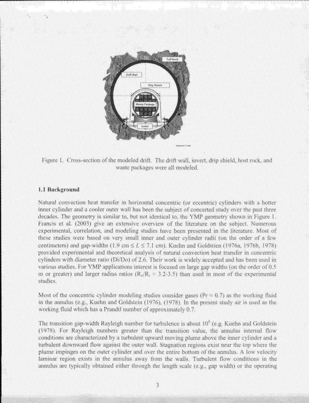
1 Comparison of CFD Natural Convection and Conduction-only Models for Heat Transfer in the Yucca Mountain Project Drifts Teklu Hadgu, Stephen W. Webb, and Michael T. Itamura N ) P m 0 m W Lo Sandia National Laboratories, Albuquerque, New Mexico ABSTRACT Yucca Mountain, Nevada has been designated as the nation's high-level radioactive waste repository and the U.S. Department of Energy has been approved to apply to the U.S. Nuclear Regulatory Commission for a license to construct a repository. Heat transfer in the Yucca Mountain Project (YMP) drift enclosures is an important aspect of repository waste emplacement. Canisters containing radioactive waste are to be emplaced in tunnels drilled 500 m below the ground surface. After repository closure, decaying heat is transferred from waste packages to the host rock by a combination of thermal radiation, natural convection and conduction heat transfer mechanism?. Current YMP mountain-scale and drift-scale numerical models often use a simplified porous medium code to model fluid and heat flow in the drift openings. To account for natural convection heat transfer, the thermal conductivity of the air was increased in the porous medium model. The equivalent thermal conductivity, defined as the ratio of total heat flow to conductive heat flow, used in the porous media models was based on horizontal concentric cylinders. Such modeling does not effectively capture turbulent natural convection in the open spaces as discussed by Webb et al. (2003) yet the approach is still widely used on the YMP project. In order to mechanistically model natural convection conditions in YMP drifts, the computational fluid dynamics (CFD) code FLUENT (Fluent, Incorporated, 2001) has been used to model natural convection heat transfer in the YMP emplacement drifts. A two-dimensional (2D) model representative of YMP geometry (e.g., includes waste package, drip shield, invert and drift wall) has been developed and numerical simulations made (Francis et al., 2003). Using CFD simulation results for both natural convection and conduction-only heat transfer in a single phase, single component fluid, equivalent thermal conductivities have been calculated for different Rayleigh numbers. Correlation equations for equivalent thermal conductivity as a function of Rayleigh number were developed for the Yucca Mountain geometry and comparisons were made to experimental data and correlations found in the literature on natural convection in horizontal concentric cylinders, a geometry similar to YMP. The objective of this work is to compare the results of CFD natural convection simulations and conduction-only calculations that used the equivalent thermal conductivity to represent heat transfer by turbulent natural convection. The FLUENT code was used for both simulations with heat generation boundary condition at the waste package and constant temperature boundary condition 5 meters into the host rock formation. Comparisons are made of temperature contours in the drift air and temperature profiles at surfaces of the different engineered components using the two 'approaches. The results show that for the two-dimensional YMP geometry considered, 1
2 the average surface temperatures of the CFD natural convection and conduction-only using the equivalent thermal conductivity are similar and the maximum local temperature differences for the different surfaces were within two 2 C. The differences in temperature profiles reflect the use of a constant equivalent thermal conductivity. The effect of the differences is discussed. 1. INTRODUCTION In order to assess the performance of the repository, studies of heat transfer and fluid flow processes in the emplacement drifts are required. Thermal radiation and turbulent natural convection in the YMP enclosures are important part of the heat transfer and fluid flow mechanisms of the post-closure in-drift environment. To better understand these mechanisms, CFD models have been developed and the models have been used to provide simplified correlations. These simplified correlations are for total heat transfer and can be used in an equivalent thermal conductivity approach in a porous media code. This paper describes some of these models and correlations, and assesses the performance of the correlations. This work summarizes two-dimensional heat transfer and fluid flow simulations in the YMP drift using the CFD software FLUENT. The work described in this report is a continuation of the CFD simulations for YMP application described in Francis et al. (2003). Heat generated by the decay of radioactive materials in spent nuclear fuel rods will be transmitted to the rock formation through materials in the drift and open spaces. In this study comparison is made of CFD natural convection and conduction-only simulation results. The model geometry consists of an emplacement drift, waste package, titanium drip shield, and a crushed rock invert providing a flow barrier at the bottom of the drift. Figure 1 shows a schematic diagram of the geometry modeled. The drift diameter is 5.5 meters. The waste packages are between 1.5 and 2.1 meters in diameter. In the CFD models presented in this paper, the heat generated by the waste packages is transmitted through radiation, natural convection and conduction. Natural convection occurs in the open spaces between the waste package and the drip shield, and between the drip shield and the drift wall. The primary focus of this study is use of heat generation boundary conditions in the waste package and constant temperature boundary conditions five meters into the rock formation. The two-dimensional CFD simulations of heat transfer in the YMP geometry are then compared to conduction-only simulations that use equivalent thermal conductivity correlations. These correlations are a function of dimensionless numbers and are expected to be applicable to variable wall temperature situations. The models did not include evaporation or condensation processes in the emplacement drift. Because of the two-dimensional modeling approach, axial heat transfer mechanisms have not also been considered. 2
3
4 conditions (e.g., temperature difference and operating pressure) of the configuration. For the very small gap widths (- 3 cm) considered in the experiments presented in the literature, air at atmospheric pressure temperatures would not result in turbulent flow (e.g., RaL < lo6). Pressurized gases such as nitrogen were often used in experiments to obtain the fluid properties necessary to achieve turbulent Rayleigh numbers for very small gap widths and small temperature differences (Kuehn and Goldstein, 1978). Most of the experimental data discussed above and presented in the literature are restricted to heat transfer results such as temperature and equivalent thermal conductivity. Experimental measurements of fluid velocity and turbulence quantities for the horizontal annulus configuration have not been published in the literature. 1.2 Equivalent Thermal Conductivity Modeling of heat transfer and fluid flow in the open areas of the drift using porous medium codes alone by assuming porous medium flow does not allow modeling of natural convection. To solve the problem the drift was modeled as a conduction-only zone with an effective thermal conductivity (Francis et al., 2003). The effective thermal conductivity attempts to model natural convection heat transfer by specifying an enhanced thermal conductivity for use in a conductiononly model. The effective thermal conductivity is defined as (Francis et al, 2003): where keff = effective thermal conductivity k, = thermal conductivity of air which is a function of temperature keq = equivalent thermal conductivity The equivalent thermal conductivity is defined as: where Q = heat transfer rate due to convection and conduction Qcond = heat transfer rate for conduction-only flow The equivalent thermal conductivity (keq) is a dimensionless quantity. The effective thermal conductivity, kefi includes the effects of natural convection and has units of W/m-K. The stagnant air thermal conductivity (k,) is a function of the average fluid temperaturewith units Wlm-k. Various authors have attempted to correlate the equivalent thermal conductivity with flow parameters. Kuehn and Goldstein (1976, 1978) provided correlating equations for the equivalent thermal conductivity as a function of Rayleigh (Nusselt) number. As detailed in Section 2 of this paper Francis et al. (2003) generated the equivalent thermal conductivity for two-dimensional natural convection in the YMP drifts using FLUENT runs with and without convection. 4
5 2. EQUIVALENT THERMAL CONDUCTIVITY DETERMINATION FOR YMP GEOMETRIES 2.1 Equivalent Thermal Conductivity Obtained Using CFD Simulations Two-dimensional CFD models with isothermal surfaces were employed to develop heat transfer correlation equations that supply effective thermal conductivities for YMP geometries required by porous media flow models (Francis et al., 2003). The CFD models included heat transfer by conduction and turbulent natural convection only. Thermal radiation was not included because the intent of this heat transfer analysis is to compute an effective thermal conductivity that approximates heat transfer by natural convection only. The CFD models used to create YMPspecific heat transfer correlation equations included different waste package diameters and all of the in-drift components discussed above with the exception of the waste package pedestal (Figure 1). Two equivalent thermal conductivity correlations were developed: one for flow conditions inside the drip shield (i.e. the inner annulus between the waste package, the drip shield and the inner invert) and a second for outside the drip shield (i.e. the outer annulus between the drip shield, drift wall and outer invert). The equivalent thermal conductivity was obtained by running FLUENT with and without gravity. With gravity, natural convection occurs in the annulus. Without gravity, heat transfer is by conduction only. For each geometry and selected temperature difference (between inner and outer surfaces), the CFD model was run in conduction-only mode to get the baseline conduction heat transfer. The total heat flux for a natural convection model was then determined in a CFD simulation. The equivalent thermal conductivity was obtained using Equation Equivalent Thermal Conductivity inside the Drip Shield For the region inside the drip shield FLUENT was run with different model parameters (e.g. waste package diameter, temperature difference). The equivalent thermal conductivity values were then plotted as a hnction of gap-width Rayleigh number. The Rayleigh number for natural convection in an annular space, based on a characteristic gap-width is, where the characteristic gap-width ( Lc,) is half the hydraulic and is given by the following relationship: where A, is the cross-sectional area and P is the wetted perimeter. It is noted that the characteristic gap-width reduces to the standard gap-width definition, R, - Ri, for a concentric cylinder annulus. 5
6 A linear fit on a log-log plot of the equivalent thermal conductivity versus Rayleigh number was used to generate a YMP-specific correlation equation for natural convection heat transfer inside the drip shield. The correlation equation is a function of the Rayleigh number, which is a function of the average temperature, temperature difference across the enclosure, and characteristic gap width. The correlation equation in terms of Rayleigh number is that given by Equation 5 (see Table 1). A more usehl form of the correlation equation for the region inside the drip shield is that given by Equation 6 (Table 1). Note that Equations 5 and 6 are only applicable inside the drip shield. Constraints for temperature difference and characteristic gap width for the YMP-specific correlation equation for natural convection heat transfer are given in Table 1. Thermal properties are evaluated at an average fluid temperature (Note: when using the second form of the equation, r is the average fluid temperature in absolute temperature, K). Equations 5 and 6 should be applied within the above constraints when evaluating the equivalent thermal conductivity for YMP geometries inside the drip shield (eccentric placement with invert and drip shield) Equivalent Thermal Conductivity outside the Drip Shield A similar correlation equation was obtained for the equivalent thermal conductivity outside the drip shield. For the region outside the drip shield the alternate form of the correlation equation is given by Equation 8 (Table 1). Note that Equations 7 and 8 are only applicable outside the drip shield. Constraints for temperature difference and characteristic gap width for the YMP-specific correlation equation for natural convection heat transfer are given in Table 1. Thermal properties are evaluated at an average fluid temperature (Note: when using the second form of the equation, T is the average fluid temperature in absolute temperature, K). Equation 8 should be applied within the above constraints when evaluating the equivalent thermal conductivity for YMP geometries outside the drip shield (eccentric placement with invert and drip shield). Table 1 summarizes each of the natural convection heat transfer correlation equations developed for YMP geometries. Figure 2 illustrates the Kuehn and Goldstein correlation equations (1976 and 1978) for natural convection heat transfer together with Equations 5 and 6. The curve labeled Kuehn & Goldstein YMP was obtained using the Kuehn and Goldstein (1978) correlation equations extended for concentric cylinders using YMP-type geometry representing the waste package and drift wall. 6

7
8 As shown in Figure 2, CFD-based equivalent thermal conductivity values are lower than those of Kuehn and Goldstein (1 976b, 1978). This indicates that geometry affects the average equivalent thermal conductivity associated with the YMP annulus. The heat transfer correlation equations developed in the literature are specifically for the annulus formed by horizontal concentric cylinders. In some instances allowances are made for eccentric placement of the inner cylinder in the correlation equations in the literature. However, these expressions do not account for changes in heat transfer due to flow blockages (e.g., invert, drip shield). It is clear that the YMP geometry with invert and drip shield is not adequately represented by literature correlation equations developed for an annulus formed by horizontal concentric cylinders. 2.2 Equivalent Thermal Conductivity Obtained Using Kuehn and Goldstein (1978) Correlations For comparison purposes the equivalent thermal conductivity was also obtained using the correlations of Kuehn and Goldstein (1 978). In developing equivalent thermal conductivity correlations for this case, separate calculations were made for the volume inside and outside of the drip shield. Because the Kuehn and Goldstein method is based on concentric cylinders, approximations were made in the YMP geometry to obtain inner and outer radii of the cylinders. In this study, the inner cylinder was represented by a single waste package diameter representing an average waste package diameter (radius = m). For the outer cylinder an effective radius was calculated representing the drip shield and the inner invert. This value was obtained using the characteristic gap width previously calculated (0.485 m) and the waste package radius (0.856 m). The gap width for two concentric cylinders is equal to the difference between the outer and inner radii. Because the inner radius (waste package) and the gap width are known, the approximate outer radius was calculated to be m. Outside the drip shield the inner cylinder radius is the outer radius of inside the drip shield. An approximate outer radius was obtained using the previously calculated gap width (1.5 m) and the inner radius (1.341 m) to be m. Using these approximate inner and outer cylinder radii and the Kuehn and Goldstein correlations, calculations were done to evaluate equivalent thermal conductivities for the regions inside and outside the drip shield. The correlation equations are shown in Table 2. 8
9 Table 2. Summary of YMP Correlation Equations for Natural Convection Heat Transfer in Enclosures based on Kuehn and Goldstein (1 978) Calculations' Location Correlation Eauation k,, = 0.052Ra,0$2 Comments 1.88~10~ I RaL, I 1.88~10~ Eq. 9 Inside Drip Shield k, = 18,584T AT K I AT I 20 "C, L, = 0.485m, is the average fluid temperature in K 10 k,, = 0.057Raiy 1.79~10~ I RaL, I 1.79~10'~ 11 Outside Drip Shield k, =36,285T AT L, K I AT I 20 OC, L, =1.5m, T is the average fluid temperature in K ke#= keq * k,( T) 3. MODEL DESCRIPTION This section describes modeling that was done to compare CFD natural convection results with those of conduction-only models that used the equivalent thermal conductivity. The FLUENT CFD code was used for all simulations with heat generation boundary condition at the waste package and a constant temperature boundary condition 5 meters into the host rock. The assumption is made that a quasi-steady-state condition exists which implies that the rate of temperature changes five meters into the rock is small enough that the volume inside of this region can be considered as a steady-state model. A description of the model is given below. 3.1 Model Geometry As described in the introduction the geometry used in this study consists of an emplacement drift, a waste package, a drip shield, and an invert (Figure 1). The geometry thus consists of two enclosed annuli: the inner annulus bounded by the waste package, the drip shield and the inside of the invert, and the outer annulus bounded by the drip shield, drift wall and outer invert. The invert provides a flow blockage at the bottom. The configuration represents a heated inner cylinder and a cooler outer cylinder. The geometric parameters of the model are shown in Table 3 and illustrated in Figure 3. The waste package is represented by the average waste package diameter. The geometries of the other drift components are as given in Francis et al. (2003). The domain for the drift CFD models is a half-cylinder 15.5 m in diameter including the rock. A shell of host rock five meters thick is 9

10
11 3.3 Boundary Conditions For the waste package, invert, and the host rock, a no heat flux boundary condition was imposed on the center-line symmetry faces (Figure 3). For the inner and outer drip shield air volumes, a no heat flux, no mass flux, and a velocity slip condition was imposed on the center-line symmetry face. For all of the solid-air interfaces, a no mass flux, no-slip boundary condition is imposed. The FLUENT code balances heat flux at those solid-air interfaces within the model. The heat is introduced into the model through a volumetric heat generation rate inside the waste package. Heat is removed from the model as a result of the constant temperature boundary condition imposed on the outer boundary of the host rock Heat Load The decaying heat of the waste packages is dependent on the waste package type and length. For this study the heat load of a waste package containing 21 pressurized water reactor fuel assemblies (21-PWR, hot) has been used. Table 5 shows the values of nominal time-dependent decay heat for the waste package. Table 5 Design basis repository power output for 21-PWR (Hot) waste package I Time [Years1 I 21-PWR AP (Hot) TW/m31 I Boundary Rock Temperature Boundary rock temperatures (5m into the rock) are given in Table 6 for the specified time periods. Rock temperatures were approximated using conduction line source solutions and superposition at a typical location within the repository. This assumption assumes a quasi-steady state solution in the model domain. Table 6 Rock boundary temperatures (5m from drift wall) Time [Years] Temperature ["C] Operating Conditions A quasi-steady state was assumed in all FLUENT simulations at the selected repository periods (300, 1000 and 3000 Years). The operating pressure selected for the numerical simulations is 11
12 ~ kpa, which is the standard atmospheric pressure at the elevation of the repository. Standard atmospheric pressure at sea level is selected to perform a comparison to literature heat transfer results for natural convection (both data and correlation equations). The specified initial gauge pressure is 0 Pa for each simulation. The absolute pressure is computed by the CFD code as the operating pressure plus the gage pressure, or kpa in this case. Gravity is specified in each of the simulations in this study as 9.81 m/s Summary of the Computational Model The CFD numerical simulation settings and runtime monitoring for equation residuals, discretization, convergence, and steady-state energy balance are described in this section for all the models. The steady-state segregated solver in FLUENT is used in this work. The segregated solver approach results in the governing equations being solved sequentially. An implicit linearization technique is applied in the segregated solution of the modeled equations previously described. This results in a linear system of equations at each computational cell. The equations are coupled and non-linear; therefore, several iterations of the equation set are required to obtain a converged solution. A Renormalization Group (RNG) k-e turbulent flow model using enhanced wall treatment was selected for use because it gives superior predictions for rapidly straining flows as well as better estimates of wall heat transfer than the standard k-e model. The mesh was refined to give y+ values (a dimensionless distance from the wall based on fluid properties and flow conditions) less than or equal to one. The discrete ordinates model (DO) with angular discretizations all set to six was used to model thermal radiation. In a11 the simulations in this work, the air inside the enclosures was treated as a radiative non participating fluid. Details of the computational approach are given by Webb and Itamura. (2004). FLUENT uses a control-volume method to solve the governing equations. The equations are discrete for each computational cell. In applying this solution method the CFD simulation stores flow properties (e.g., dependent variables) at cell centers. However, face values are required for the convection terms in the discretized equations. Face values are obtained by interpolation from the cell centers using a second-order upwind scheme for the momentum and energy equations and a first-order upwind scheme for the turbulence equations. It is noted that the difhsion terms in the equations are central-differenced and are second-order accurate. The body-force-weighted pressure interpolation scheme is applied to this analysis. The pressure interpolation scheme is used to compute face pressures from cell center values. A body-force-weighted pressure interpolation scheme is applicable to buoyancy driven flows. Pressure-velocity coupling is achieved through the SIMPLE (Semi-Implicit Method for Pressure-Linked Equations) algorithm. The SIMPLE algorithm uses the discrete continuity equation to determine a cell pressure correction equation. Once a solution to the cell pressure correction equation is obtained the cell pressure and face mass fluxes are then corrected using the cell pressure correction term. The flow solution is given an arbitrary initial starting point for fluid velocity, temperature, and turbulence quantities. Additional iterations are required for solution convergence. A flow solution is considered to have converged after all equation residuals have been reduced by several orders of magnitude. A final convergence criteria specified in the CFD simulations is 12
13 based on an overall steady-state energy balance. In addition changes in variables such as temperature and velocity are monitored for convergence. When the energy imbalance is about 0.5% or less and changes in variables are low, it is assumed that stead-state is reached and the flow simulation is complete. 4. COMPUTATION RESULTS FLUENT calculations were carried out with a 21 PWR (hot) heat generation source at three different time periods after repository waste emplacement: 300 years, 1000 years and 3000 years. For each case considered two calculations were done: natural convection (termed CFD), and conduction only with equivalent thermal conductivities obtained using a User Defined Function (A FLUENT macro containing the equivalent thermal conductivity correlations) (termed ETC). To compare results of CFD based equivalent thermal conductivities (i.e. ETC) with those of Kuehn and Goldstein (1 978) correlations, additional FLUENT calculations were also made with the 21 PWR (hot) power source at the three time periods. The Kuehn and Goldstein based conduction calculations (termed K&G) are discussed in Section Comparison of CFD and Conduction only ETC results Three calculations were performed at the selected three time periods Average Temperatures At 300 years, the heat generation rates of waste packages are still relatively high. Table 7 shows average temperature predictions for the different surfaces and the air inside and outside the drip shield for the three types of FLUENT calculations at 300 years. The waste package temperatures for this case are high due to the high heat source and high rock temperature boundary condition. The CFD predicted average waste package temperature is "C, which is above boiling. Since these calculations are for single-phase airflow, evaporation of water (phase change) is not modeled. As shown in Table 7 the ETC over predicted the CFD average waste package temperature by about 0.35 "C. Predictions of average drip shield and drift wall temperatures ETC were about the same as those of the CFD. ETC predictions of inner invert and outer invert average temperatures were higher than those of the CFD by about 1.02 "C and 0.48 "C respectively. The predicted average air temperature inside the drip shield for ETC is higher than the CFD by about 0.2 "C. The predicted average air temperature outside the drip shield for ETC is lower than the CFD by about 0.26 "C. 13
14 Table 7: Calculated Average temperature ["C] at 300 years Body Waste Package Drip Shield Drift Wall CFD ETC CFD-ETC I Inner-Invert I I I Outer-Invert Inner- Air I Outer-Air I I I 0.26 At 1000 years decaying of the heat source has significantly reduced the heat generation rates of waste packages. Table 8 shows average temperature predictions for the different surfaces and the air inside and outside the drip shield for the three types of FLUENT calculations at 1000 years. The waste package temperatures for this case are still high due to the significant heat source and high rock temperature boundary condition. The CFD predicted average waste package temperature is "C, which is slightly above boiling for the location. As shown in Table 8 the ETC over predicted the CFD average waste package temperature by about 0.18 K, which is about half of the 300-year case. Predictions of average drip shield and drift wall temperatures of ETC were about the same as those of the CFD. ETC predictions of inner invert and outer invert average temperatures were higher than those of the CFD by about 0.54 "C and 0.25 "C respectively. The predicted average air temperature inside the drip shield for ETC is higher than the CFD by about 0.1 "C. The predicted average air temperature outside the drip shield for ETC is lower than the CFD by about 0.13 "C. Overall, the heat generation rate at 1000 years is less than half of that at 300 years, and temperature.predictions for the conduction only calculations and CFD are reduced by about half. Table 8: Calculated Average temperature ["C] at 1000 years Waste Package Drir, Shield Drift Wall Inner-Invert Outer-Invert Inner- Air Outer- Air At 3000 years decaying of the heat source has significantly reduced the heat generation rates of waste packages. Table 9 shows average temperature predictions for the different surfaces and the air inside and outside the drip shield for the three types of FLUENT calculations at 3000 years. The waste package temperatures for this case are much lower than those of the 300-year and 1000-year calculations due to the much lower heat source and relatively lower rock temperature 14
15 boundary condition. The CFD predicted average waste package temperature is "C, which is below boiling. As shown in Table 9 the ETC over predicted the CFD average waste package temperature by about 0.1 "C. Predictions of average drip shield and drift wall temperatures of ETC were about the same as those of the CFD. ETC predictions of inner invert and outer invert average temperatures were higher than those of the CFD by about 0.29 "C and 0.13 "C respectively. The predicted average air temperature inside the drip shield for ETC is higher than the CFD by about 0.05 "C. The predicted average air temperature outside the drip shield for ETC is lower than the CFD by about 0.07 "C. Table 9: Calculated Average temperature ["C] at 3000 years Waste Package DriD Shield Drik Wall Inner-Invert Outer-Invert %ner-air Outer- Air I Comparing the CFD results in Tables 7 to 9 periods the average air temperature inside the drip shield is lower than the average inner invert surface temperature. This indicates that heat is transferred from the inner invert to the air. The hot surface on the inner invert is caused by thermal radiation from the waste package. For the region outside the drip shield the average air temperature is higher than the average drift wall temperature and outer invert. Thus, heat is transferred from the air to these surfaces. At the local pressure (89.05 kpa) the boiling point is about 96 "C. Thus, the average temperatures at all surfaces for the 300-year calculations are above boiling. For the year calculations temperatures are near the boiling temperature and for the 3000-year calculations temperatures are below boiling. The differences in temperature indicate that there is a potential for moisture movement inside the drift. Note that local variations exist as shown in the temperature profile plots. Table 10 shows equivalent thermal conductivity and Rayleigh number values at the three times. The Rayleigh numbers indicate that the flow is turbulent in all cases. Table 10: Equivalent thermal conductivity and Gap-width Rayleigh number for the CFD calculations at the three times. RaL, ks RaL, Time [Year] Inside Drip Inside Drip Outside Drip Shield Shield Shield x 10' x 10' x lo x lo x lo x lo8 kq Outside Drip Shield
16 4.1.2 Surface Temperature Profiles Figure 4 illustrates the local temperature variations predicted of CFD and ETC simulations at the 300-year time period for all surfaces. Figure 5 shows waste package surface temperatures versus vertical position for 300 years. As shown in Figures 5 some prediction differences exist between CFD and ETC all along the length of the surface. ETC under predicts local temperatures on the upper part of the waste package surface but over predicts for the rest of the surface. For the 300- year calculations the largest differences are at the bottom of the waste package where the ETC model over predicts temperatures by as much as 1.70 "C. For the 1000-year and 3000-year calculations the corresponding over predictions are 0.87 "C and 0.42 "C, respectively. Similar temperature profiles of the waste package surface were obtained for 1000 and 3000 years, with lower temperatures. This shows that the waste package surface temperatures vary with position and time period. Due to the higher power generation the variation with position is larger at the earliest 300 years). [Also, Tables 7 to 9 and the temperature profiles show that both the average and local temperatures are highest at the earlier time. This is true for all surfaces.] As with the average temperature predictions (Tables 7 to 9) temperature profiles for the drip shield and drift wall surfaces of CFD and ETC at all time periods are very close to each other (see Figure 4 for 300-year results). ETC local temperature predictions on these surfaces are similar to those of the CFD. Figure 6 shows temperature profiles for combined inner and outer invert surfaces for 300 years. The inner invert extends from 0 to 1.25 m and the outer invert from 1.25 m to 1.95 m. The results at the three time periods show that for the inner invert ETC local temperatures over predict those of the CFD by as much as about 1.5 "C for 300-year calculations (Figure 6), 0.80 for 1000-year calculations and 0.4 for 3000-year calculations. The largest differences are at locations near the waste package. Away from the waste package the differences in the predicted local temperatures are reduced and about zero at the drip shield. In the outer invert the differences at both ends (drip shield and drift wall) are minimal. Some differences exist at locations between the ends. Plots of temperature versus position for specified lines measured from the center of the waste package are shown in Figure 7 for the 300-year time period. The positive vertical symmetry line is at zero degrees. The width of the two annular spaces varies depending on the inclination of the line. The lines show gradual temperature reduction from the waste package to the outer edge of the rock formation. For the CFD case the flatter parts of the lines represent the temperatures in the air inside and outside the drip shield, showing gradual temperature variations in the open spaces within an line. However, the different lines show that air temperatures are higher near the top, a result of an upward moving air by natural convection. The sharp drops at the beginning or end of the flat CFD lines (Le. near surfaces) indicate boundary layer behavior. For the ETC, temperature changes across the open spaces are more pronounced, indicative of temperature gradient by conduction across a body. The ETC predicts higher air temperatures at the bottom. As expected both the CFD and ETC simulations give the same result for conduction through solid materials. 16
17 For the CFD simulations, heat transfer by thermal radiation and natural convection influence the temperature predictions. For the ETC simulations, thermal radiation and conduction are important. However, the effect of thermal radiation on temperature is more important than both natural convection and conduction. Figure 8 shows convective (CFD) and conductive (ETC) flux variations at the waste package surface for the 300-year time period. The plots show that for the most part the convective flux (CFD) increases from top to bottom. The conductive flux (ETC) does not follow the same pattern. For the ETC the conductive flux variations reflect distances between surfaces of the inner annular space. Thus, the heat flux increases as the distance between surfaces is reduced. It is clear from the results shown that the conduction only temperature profiles do not always replicate the CFD local temperature variations. The differences in temperature profiles reflect the use of a constant equivalent thermal conductivity for each open space. As shown in Francis et al. (2003) the equivalent thermal conductivity varies with location. But in many locations the differences in predicted temperatures are minimal, and thus the conduction only simulations reasonably replicate CFD results. Also, if the average temperature is sufficient, as in many applications at YMP, then the conduction only simulation results could be a good substitute for turbulent natural convection. Evaporation and condensation can occur inside of the drift. As shown in Tables 7 to 9 and the temperature profile plots the CFD and ETC temperature predictions at the cooler surfaces are very close. Prediction discrepancies are more pronounced at hotter surfaces. Thus, it can be concluded that use of the conduction only results would have minimal adverse effects for the possible occurrence of condensation. As stated in Section 1 the equivalent thermal conductivity method was not designed for multiphase flows, and the twodimensional modeling approach may potentially mask axial variations in temperature. [The use of the equivalent thermal conductivity correlations assumes that flow patterns are known, which in this case represent 2-D. Differences in 2-D versus 3-D simulation are discussed by Itamura et al. (2004). Future work, comparing 3-D drift temperatures from CFD calculations with 2-D equivalent thermal conductivity predictions, is underway.] 17

18

19

20
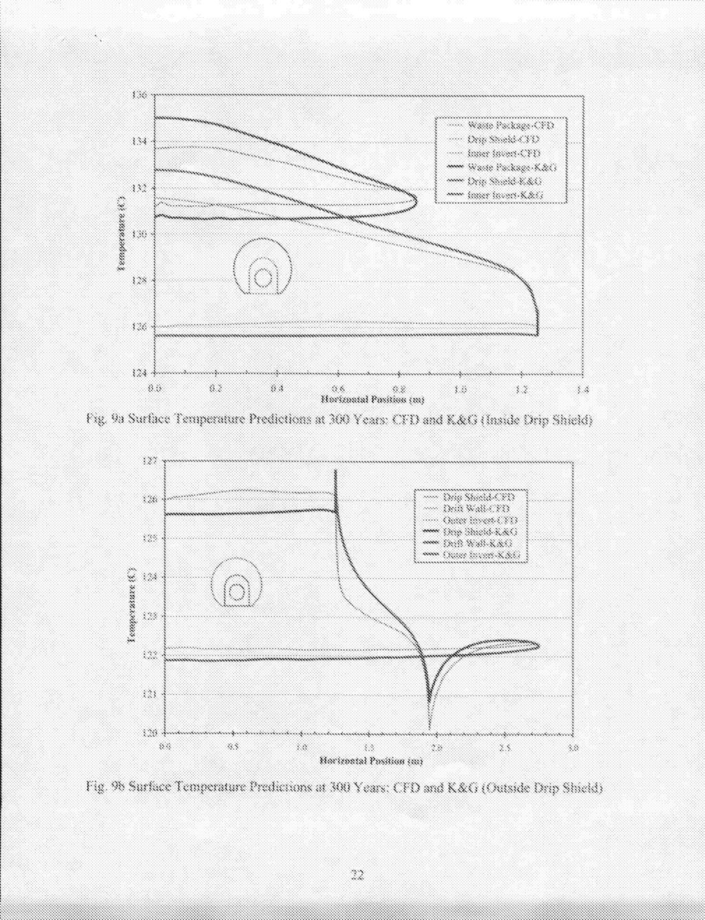
21 4.2 Comparison of CFD and Kuehn and Goldstein (1978) based Conduction-only Model Results Results of the Kuehn and Goldstein based FLUENT simulations are given in Table 11 and Figures 9 and 10 together with the CFD and ETC predictions. Table 11 shows that average temperature predictions of Kuehn and Goldstein based conduction-only calculations (K&G) are similar to those of CFD-based calculations (ETC). However, variations exist in local temperature predictions (see Figures 9 and 10). In Figure 10 the K&G temperature curve is to the left of the ETC curve. At the bottom of the waste package the K&G temperatures are slightly closer to those of the CFD than those of the ETC. The K&G temperature predictions are worse at the top of the waste package. The results show that although the equivalent thermal conductivity correlations for both the ETC and K&G were based on approximately similar geometry, the underlying Kuehn and Goldstein (1 978) method was not designed for the complex YMP geometry. Table 11: Calculated Average temperature ["C] at 300 years Waste Package DriD Shield Drk Wall Inner-Invert Outer-Invert Inner- Air Outer- Air
22

23
24 method was not designed for multiphase flows, and the two-dimensional modeling approach may potentially mask variations in temperature down the drift. The Kuehn and Goldstein (1978) method was also used to provide equivalent thermal conductivity correlations for comparison with the CFD-based correlations. Results showed that although the equivalent thermal conductivity correlations for both methods were based on approximately similar geometry, the Kuehn and Goldstein (1 978) method over predicts the turbulent natural convection, which results in lower temperatures. The use of the equivalent thermal conductivity correlations assumes that flow patterns are known, which in this case represent 2-D. Differences in 2-D versus 3-D simulation are discussed by Itamura et al. (2004). Work comparing 3-D drift temperatures from CFD calculations with 2- D equivalent thermal conductivity predictions is currently underway. 6. ACKNOWLEDGEMENTS The authors would like to thank Darryl James of Texas Tech University in Lubbock, Texas for his contribution in providing a user defined function for effective thermal conductivity calculation. This work was supported by the Yucca Mountain Site Characterization Office as part of the Office of Civilian Radioactive Waste Management (OCRWM), which is managed by the U.S. Department of Energy, Yucca Mountain Site Characterization Project. Sandia is a multiprogram laboratory operated by Sandia Corporation, a Lockheed Martin Company, for the United States Department of Energy under Contract DE-AC04-94AL REFERENCES Fluent Incorporated FLUENT 6 User's Guide. Volumes 1 to 5. Lebanon, New Hampshire: FLUENT Incorporated. Francis, N.D., Jr.; Itamura, M.T.; Webb, S.W.; and James, D.L CFD Calculation of Internal Natural Convection in the Annulus Between Horizontal Concentric Cylinders. SAND Albuquerque, New Mexico: Sandia National Laboratories. Francis, N.D.,Jr.; Webb, S.W.; Itamura, M.T.; and James, D.L CFD Modeling of Natural Convection Heat Transfer and Fluid Flow in Yucca Mountain Project (YW) Enclosures. SAND Albuquerque, New Mexico: Sandia National Laboratories. Incropera, F.P. and DeWitt, D.P Fundamentals of Heat and Mass Transfer. 3rd Edition. New York, New York: John Wiley & Sons. Itamura, M.T.; Francis, N.D.,Jr.; and Webb, S.W In-Drift Natural Convection Analysis of the Low Temperature Operating Mode Design. Submitted for publication in Nuclear Technology. 24
25 Kuehn, T.H. and Goldstein, R.J "Correlating Equations for Natural Convection Heat Transfer Between Horizontal Circular Cylinders." International Journal of Heat and Mass Transfer, 19, (1 0), New York, New York: Pergamon Press. Kuehn, T.H. and Goldstein, R.J "An Experimental Study of Natural Convection Heat Transfer in Concentric and Eccentric Horizontal Cylindrical Annuli." Journal of Heat Transfer, 100, ([4]), [New York, New York: American Society of Mechanical Engineers]. Webb, S.W., Francis, N.D., Dum, S.D., Itamura, M.T., and James, D.L "Thermally- Induced Natural Convection Effects in Yucca Mountain Drifts." Journal of Contaminant Hydrology. Volume 62-63, pp Webb, S.W., and M.T. Itamura, 2004, "Calculation of Post-Closure Natural Convection Heat and Mass Transfer in Yucca mountain Drifts," ASME Paper HT-FED , these proceedings. 25
A 2-D Test Problem for CFD Modeling Heat Transfer in Spent Fuel Transfer Cask Neutron Shields. G Zigh and J Solis U.S. Nuclear Regulatory Commission
 CFD4NRS2010 A 2-D Test Problem for CFD Modeling Heat Transfer in Spent Fuel Transfer Cask Neutron Shields G Zigh and J Solis U.S. Nuclear Regulatory Commission Abstract JA Fort Pacific Northwest National
THE APPLICATION OF CFD TO VENTILATION CALCULATIONS AT YUCCA MOUNTAIN
 THE APPLICATION OF CFD TO VENTILATION CALCULATIONS AT YUCCA MOUNTAIN G Danko, and D Bahrami, Mackay School of Mines University of Nevada, Reno Reno, NV 89557, (775) 784 4284 ABSTRACT This paper presents
Deep Borehole Disposal Performance Assessment and Criteria for Site Selection
 Deep Borehole Disposal Performance Assessment and Criteria for Site Selection Sandia is a multiprogram laboratory operated by Sandia Corporation, a Lockheed Martin Company, for the United States Department
Natural Convection from a Long Horizontal Cylinder
 Natural Convection from a Long Horizontal Cylinder Hussein Awad Kurdi Saad Engineering Technical College of Al Najaf, Al-Furat Al-Awsat Technical University, Iraq ABSTRACT: Natural convection from a Long
COMPUTATIONAL FLUID DYNAMICS MODELING APPROACH TO EVALUATE VSC 17 DRY STORAGE CASK THERMAL DESIGNS
 COMPUTATIONAL FLUID DYNAMICS MODELING APPROACH TO EVALUATE VSC 17 DRY STORAGE CASK THERMAL DESIGNS Kaushik Das, * Debashis Basu, * Jorge Solis, ** Ghani Zigh ** *Center for Nuclear Waste Regulatory Analyses
Analysis of the Cooling Design in Electrical Transformer
 Analysis of the Cooling Design in Electrical Transformer Joel de Almeida Mendes E-mail: joeldealmeidamendes@hotmail.com Abstract This work presents the application of a CFD code Fluent to simulate the
EXPERIMENTAL AND NUMERICAL STUDIES OF A SPIRAL PLATE HEAT EXCHANGER
 THERMAL SCIENCE: Year 2014, Vol. 18, No. 4, pp. 1355-1360 1355 EXPERIMENTAL AND NUMERICAL STUDIES OF A SPIRAL PLATE HEAT EXCHANGER by Rangasamy RAJAVEL Department of Mechanical Engineering, AMET University,
Keywords: Spiral plate heat exchanger, Heat transfer, Nusselt number
 EXPERIMENTAL AND NUMERICAL STUDIES OF A SPIRAL PLATE HEAT EXCHANGER Dr.RAJAVEL RANGASAMY Professor and Head, Department of Mechanical Engineering Velammal Engineering College,Chennai -66,India Email:rajavelmech@gmail.com
ANALYSIS OF NATURAL CONVECTION IN HORIZONTAL CONCENTRIC ANNULI OF VARYING INNER SHAPE
 Numerical Heat Transfer, Part A, 68: 1155 1174, 2015 Copyright # Taylor & Francis Group, LLC ISSN: 1040-7782 print=1521-0634 online DOI: 10.1080/10407782.2015.1032016 ANALYSIS OF NATURAL CONVECTION IN
PEAK CLADDING TEMPERATURE IN A SPENT FUEL STORAGE OR TRANSPORTATION CASK. Argonne, IL Reno, NV 89557
 Proceedings of the 15th International Symposium on the Packaging and Transportation of Radioactive Materials PATRAM 27 October 21-26, 27, Miami, Florida, USA PEAK CLADDING TEMPERATURE IN A SPENT FUEL STORAGE
EFFECT OF DISTRIBUTION OF VOLUMETRIC HEAT GENERATION ON MODERATOR TEMPERATURE DISTRIBUTION
 EFFECT OF DISTRIBUTION OF VOLUMETRIC HEAT GENERATION ON MODERATOR TEMPERATURE DISTRIBUTION A. K. Kansal, P. Suryanarayana, N. K. Maheshwari Reactor Engineering Division, Bhabha Atomic Research Centre,
MODELING WATER SEEPAGE INTO HEATED WASTE EMPLACEMENT DRIFTS AT YUCCA MOUNTAIN
 PROCEEDINGS, TOUGH Symposium 2003 Lawrence Berkeley National Laboratory, Berkeley, California, May 12 14, 2003 MODELING WATER SEEPAGE INTO HEATED WASTE EMPLACEMENT DRIFTS AT YUCCA MOUNTAIN Jens Birkholzer,
Cooling by Free Convection at High Rayleigh Number of Cylinders Positioned Above a Plane
 16 th Australasian Fluid Mechanics Conference Crown Plaza, Gold Coast, Australia 2-7 December 2007 Cooling by Free Convection at High Rayleigh Number of Cylinders Positioned Above a Plane B.P. Huynh Faculty
INSTRUCTOR: PM DR MAZLAN ABDUL WAHID
 SMJ 4463: HEAT TRANSFER INSTRUCTOR: PM ABDUL WAHID http://www.fkm.utm.my/~mazlan TEXT: Introduction to Heat Transfer by Incropera, DeWitt, Bergman, Lavine 5 th Edition, John Wiley and Sons Chapter 9 Natural
Introduction. Statement of Problem. The governing equations for porous materials with Darcy s law can be written in dimensionless form as:
 Symbolic Calculation of Free Convection for Porous Material of Quadratic Heat Generation in a Circular Cavity Kamyar Mansour Amirkabir University of technology, Tehran, Iran, 15875-4413 mansour@aut.ac.ir
THERMAL HYDRAULIC REACTOR CORE CALCULATIONS BASED ON COUPLING THE CFD CODE ANSYS CFX WITH THE 3D NEUTRON KINETIC CORE MODEL DYN3D
 THERMAL HYDRAULIC REACTOR CORE CALCULATIONS BASED ON COUPLING THE CFD CODE ANSYS CFX WITH THE 3D NEUTRON KINETIC CORE MODEL DYN3D A. Grahn, S. Kliem, U. Rohde Forschungszentrum Dresden-Rossendorf, Institute
DNS of Buoyancy Driven Flow Inside a Horizontal Coaxial Cylinder
 DNS of Buoyancy Driven Flow Inside a Horizontal Coaxial Cylinder Imama Zaidi 1, Yacine Addad 2, Dominique Laurence 1 1 The University of Manchester, School of Mechanical, Aerospace and Civil Eng., M60
Chapter 9 NATURAL CONVECTION
 Heat and Mass Transfer: Fundamentals & Applications Fourth Edition in SI Units Yunus A. Cengel, Afshin J. Ghajar McGraw-Hill, 2011 Chapter 9 NATURAL CONVECTION PM Dr Mazlan Abdul Wahid Universiti Teknologi
CFD Analysis of Forced Convection Flow and Heat Transfer in Semi-Circular Cross-Sectioned Micro-Channel
 CFD Analysis of Forced Convection Flow and Heat Transfer in Semi-Circular Cross-Sectioned Micro-Channel *1 Hüseyin Kaya, 2 Kamil Arslan 1 Bartın University, Mechanical Engineering Department, Bartın, Turkey
This chapter focuses on the study of the numerical approximation of threedimensional
 6 CHAPTER 6: NUMERICAL OPTIMISATION OF CONJUGATE HEAT TRANSFER IN COOLING CHANNELS WITH DIFFERENT CROSS-SECTIONAL SHAPES 3, 4 6.1. INTRODUCTION This chapter focuses on the study of the numerical approximation
This section develops numerically and analytically the geometric optimisation of
 7 CHAPTER 7: MATHEMATICAL OPTIMISATION OF LAMINAR-FORCED CONVECTION HEAT TRANSFER THROUGH A VASCULARISED SOLID WITH COOLING CHANNELS 5 7.1. INTRODUCTION This section develops numerically and analytically
Water, Vapor, and Salt Dynamics in a Hot Repository
 Water, Vapor, and Salt Dynamics in a Hot Repository Davood Bahrami 1, George Danko 1, and John Walton 2 1 Department of Mining Engineering, University of Nevada, Reno, 1664 N. Virginia St., Reno, NV, 89557
CHAPTER 7 NUMERICAL MODELLING OF A SPIRAL HEAT EXCHANGER USING CFD TECHNIQUE
 CHAPTER 7 NUMERICAL MODELLING OF A SPIRAL HEAT EXCHANGER USING CFD TECHNIQUE In this chapter, the governing equations for the proposed numerical model with discretisation methods are presented. Spiral
C ONTENTS CHAPTER TWO HEAT CONDUCTION EQUATION 61 CHAPTER ONE BASICS OF HEAT TRANSFER 1 CHAPTER THREE STEADY HEAT CONDUCTION 127
 C ONTENTS Preface xviii Nomenclature xxvi CHAPTER ONE BASICS OF HEAT TRANSFER 1 1-1 Thermodynamics and Heat Transfer 2 Application Areas of Heat Transfer 3 Historical Background 3 1-2 Engineering Heat
Chapter 2 HEAT CONDUCTION EQUATION
 Heat and Mass Transfer: Fundamentals & Applications 5th Edition in SI Units Yunus A. Çengel, Afshin J. Ghajar McGraw-Hill, 2015 Chapter 2 HEAT CONDUCTION EQUATION Mehmet Kanoglu University of Gaziantep
Chapter 2 HEAT CONDUCTION EQUATION
 Heat and Mass Transfer: Fundamentals & Applications Fourth Edition Yunus A. Cengel, Afshin J. Ghajar McGraw-Hill, 2011 Chapter 2 HEAT CONDUCTION EQUATION Mehmet Kanoglu University of Gaziantep Copyright
Influence of Heat Transfer Process in Porous Media with Air Cavity- A CFD Analysis
 Proceedings of the 4 th International Conference of Fluid Flow, Heat and Mass Transfer (FFHMT'17) Toronto, Canada August 21 23, 2017 Paper No. 161 DOI: 10.11159/ffhmt17.161 Influence of Heat Transfer Process
Convection. forced convection when the flow is caused by external means, such as by a fan, a pump, or atmospheric winds.
 Convection The convection heat transfer mode is comprised of two mechanisms. In addition to energy transfer due to random molecular motion (diffusion), energy is also transferred by the bulk, or macroscopic,
Laminar flow heat transfer studies in a twisted square duct for constant wall heat flux boundary condition
 Sādhanā Vol. 40, Part 2, April 2015, pp. 467 485. c Indian Academy of Sciences Laminar flow heat transfer studies in a twisted square duct for constant wall heat flux boundary condition RAMBIR BHADOURIYA,
Project #1 Internal flow with thermal convection
 Project #1 Internal flow with thermal convection MAE 494/598, Fall 2017, Project 1 (20 points) Hard copy of report is due at the start of class on the due date. The rules on collaboration will be released
HEAT TRANSFER CAPABILITY OF A THERMOSYPHON HEAT TRANSPORT DEVICE WITH EXPERIMENTAL AND CFD STUDIES
 HEAT TRANSFER CAPABILITY OF A THERMOSYPHON HEAT TRANSPORT DEVICE WITH EXPERIMENTAL AND CFD STUDIES B.M. Lingade a*, Elizabeth Raju b, A Borgohain a, N.K. Maheshwari a, P.K.Vijayan a a Reactor Engineering
Clifford K. Ho and Michael L. Wilson Sandia National Laboratories. P.O. Box Albuquerque, NM
 1 L Calculation of Discrete Fracture Flow Paths in Dual-Continuum Models W + 0 Clifford K. Ho and Michael L. Wilson Sandia National Laboratories P.O. Box 5800 Albuquerque, NM 87 185-1324 ckho@sandia.gov,
Available online at ScienceDirect. Procedia Engineering 90 (2014 )
") Available online at www.sciencedirect.com ScienceDirect Procedia Engineering 9 (24 ) 55 556 th International Conference on Mechanical Engineering, ICME 23 Analysis of heat transfer and flow due to natural
Available online at www.sciencedirect.com ScienceDirect Procedia Engineering 9 (24 ) 55 556 th International Conference on Mechanical Engineering, ICME 23 Analysis of heat transfer and flow due to natural
THERMAL PERFORMANCE EVALUATION OF AN INNOVATIVE DOUBLE GLAZING WINDOW
 THERMAL PERFORMANCE EVALUATION OF AN INNOVATIVE DOUBLE GLAZING WINDOW Luigi De Giorgi, Carlo Cima, Emilio Cafaro Dipartimento di Energetica, Politecnico di Torino, Torino, Italy Volfango Bertola School
Natural convection heat transfer around a horizontal circular cylinder near an isothermal vertical wall
 Natural convection heat transfer around a horizontal circular cylinder near an isothermal vertical wall Marcel Novomestský 1, Richard Lenhard 1, and Ján Siažik 1 1 University of Žilina, Faculty of Mechanical
Introduction to Heat and Mass Transfer. Week 14
 Introduction to Heat and Mass Transfer Week 14 HW # 7 prob. 2 Hot water at 50C flows through a steel pipe (thermal conductivity 14 W/m-K) of 100 mm outside diameter and 8 mm wall thickness. During winter,
Convection Workshop. Academic Resource Center
 Convection Workshop Academic Resource Center Presentation Outline Understanding the concepts Correlations External Convection (Chapter 7) Internal Convection (Chapter 8) Free Convection (Chapter 9) Solving
Introduction to Heat Transfer
 FIFTH EDITION Introduction to Heat Transfer FRANK P. INCROPERA College of Engineering University ofnotre Dame DAVID P. DEWITT School of Mechanical Purdue University Engineering THEODORE L. BERGMAN Department
Analysis and interpretation of the LIVE-L6 experiment
 Analysis and interpretation of the LIVE-L6 experiment A. Palagin, A. Miassoedov, X. Gaus-Liu (KIT), M. Buck (IKE), C.T. Tran, P. Kudinov (KTH), L. Carenini (IRSN), C. Koellein, W. Luther (GRS) V. Chudanov
COMPUTATIONAL ANALYSIS OF LAMINAR FORCED CONVECTION IN RECTANGULAR ENCLOSURES OF DIFFERENT ASPECT RATIOS
 HEFAT214 1 th International Conference on Heat Transfer, Fluid Mechanics and Thermodynamics 14 16 July 214 Orlando, Florida COMPUTATIONAL ANALYSIS OF LAMINAR FORCED CONVECTION IN RECTANGULAR ENCLOSURES
CFD STUDIES IN THE PREDICTION OF THERMAL STRIPING IN AN LMFBR
 CFD STUDIES IN THE PREDICTION OF THERMAL STRIPING IN AN LMFBR K. Velusamy, K. Natesan, P. Selvaraj, P. Chellapandi, S. C. Chetal, T. Sundararajan* and S. Suyambazhahan* Nuclear Engineering Group Indira
FLUID FLOW AND HEAT TRANSFER INVESTIGATION OF PERFORATED HEAT SINK UNDER MIXED CONVECTION 1 Mr. Shardul R Kulkarni, 2 Prof.S.Y.
 FLUID FLOW AND HEAT TRANSFER INVESTIGATION OF PERFORATED HEAT SINK UNDER MIXED CONVECTION 1 Mr. Shardul R Kulkarni, 2 Prof.S.Y.Bhosale 1 Research scholar, 2 Head of department & Asst professor Department
If there is convective heat transfer from outer surface to fluid maintained at T W.
 Heat Transfer 1. What are the different modes of heat transfer? Explain with examples. 2. State Fourier s Law of heat conduction? Write some of their applications. 3. State the effect of variation of temperature
FINITE ELEMENT ANALYSIS OF MIXED CONVECTION HEAT TRANSFER ENHANCEMENT OF A HEATED SQUARE HOLLOW CYLINDER IN A LID-DRIVEN RECTANGULAR ENCLOSURE
 Proceedings of the International Conference on Mechanical Engineering 2011 (ICME2011) 18-20 December 2011, Dhaka, Bangladesh ICME11-TH-014 FINITE ELEMENT ANALYSIS OF MIXED CONVECTION HEAT TRANSFER ENHANCEMENT
Table 17 1 Some general field equation terms. Heat Power. Current Source. 0 0 Boundary Current Porous Media Flow. Flow Source
 17 Related Analogies 17.1 Basic Concepts The differential equation used in a finite element study in one discipline often appears in a different discipline, but with a different physical meaning for the
CONVECTION HEAT TRANSFER
 CONVECTION HEAT TRANSFER SECOND EDITION Adrian Bejan J. A. Jones Professor of Mechanical Engineering Duke University Durham, North Carolina A WILEY-INTERSCIENCE PUBUCATION JOHN WILEY & SONS, INC. New York
NUMERICAL SIMULATION OF FLOW AND HEAT TRANSFER AROUND VERTICAL CYLINDER SUBMERGED IN WATER
 NUMERICAL SIMULATION OF FLOW AND HEAT TRANSFER AROUND VERTICAL CYLINDER SUBMERGED IN WATER Ahmed Ramadan*, ahmed.ramadan@northumbria.ac.uk Reaz Hasan, reaz.hasan@northumbria.ac.uk Roger Penlington, r.penlington@northumbria.ac.uk
Theoretical and Experimental Studies on Transient Heat Transfer for Forced Convection Flow of Helium Gas over a Horizontal Cylinder
 326 Theoretical and Experimental Studies on Transient Heat Transfer for Forced Convection Flow of Helium Gas over a Horizontal Cylinder Qiusheng LIU, Katsuya FUKUDA and Zheng ZHANG Forced convection transient
Analysis of Heat Transfer in Pipe with Twisted Tape Inserts
 Proceedings of the 2 nd International Conference on Fluid Flow, Heat and Mass Transfer Ottawa, Ontario, Canada, April 30 May 1, 2015 Paper No. 143 Analysis of Heat Transfer in Pipe with Twisted Tape Inserts
Hydrogeology of Deep Borehole Disposal for High-Level Radioactive Waste
 SAND2014-18615C Hydrogeology of Deep Borehole Disposal for High-Level Radioactive Waste Geological Society of America Annual Meeting October 20, 2014 Bill W. Arnold, W. Payton Gardner, and Patrick V. Brady
THE USE OF PB-BI EUTECTIC AS THE COOLANT OF AN ACCELERATOR DRIVEN SYSTEM. Joint research Centre of the European Commission Ispra, Italy.
 THE USE OF PB-BI EUTECTIC AS THE COOLANT OF AN ACCELERATOR DRIVEN SYSTEM Alberto Peña 1, Fernando Legarda 1, Harmut Wider 2, Johan Karlsson 2 1 University of the Basque Country Nuclear Engineering and
Department of Energy Science & Engineering, IIT Bombay, Mumbai, India. *Corresponding author: Tel: ,
 ICAER 2011 AN EXPERIMENTAL AND COMPUTATIONAL INVESTIGATION OF HEAT LOSSES FROM THE CAVITY RECEIVER USED IN LINEAR FRESNEL REFLECTOR SOLAR THERMAL SYSTEM Sudhansu S. Sahoo* a, Shinu M. Varghese b, Ashwin
Numerical investigation of the buoyancy-induced flow field and heat transfer inside solar chimneys
 Numerical investigation of the buoyancy-induced flow field and heat transfer inside solar chimneys E. BACHAROUDIS, M.GR. VRACHOPOULOS, M.K. KOUKOU, A.E. FILIOS Mechanical Engineering Department, Environmental
Documentation of the Solutions to the SFPE Heat Transfer Verification Cases
 Documentation of the Solutions to the SFPE Heat Transfer Verification Cases Prepared by a Task Group of the SFPE Standards Making Committee on Predicting the Thermal Performance of Fire Resistive Assemblies
Vertical Mantle Heat Exchangers for Solar Water Heaters
 for Solar Water Heaters Y.C., G.L. Morrison and M. Behnia School of Mechanical and Manufacturing Engineering The University of New South Wales Sydney 2052 AUSTRALIA E-mail: yens@student.unsw.edu.au Abstract
Studies on flow through and around a porous permeable sphere: II. Heat Transfer
 Studies on flow through and around a porous permeable sphere: II. Heat Transfer A. K. Jain and S. Basu 1 Department of Chemical Engineering Indian Institute of Technology Delhi New Delhi 110016, India
THERMO-FLOW CHARACTERISTICS OF A PIN-FIN RADIAL HEAT SINKS ACCORDING TO THEIR FIN HEIGHT PROFILE
 HEFAT2012 9 th International Conference on Heat Transfer, Fluid Mechanics and Thermodynamics 16 18 July 2012 Malta THERMO-FLOW CHARACTERISTICS OF A PIN-FIN RADIAL HEAT SINKS ACCORDING TO THEIR FIN HEIGHT
ANALYSIS OF FLOW IN A CONCENTRIC ANNULUS USING FINITE ELEMENT METHOD
 Nigerian Journal of Technology (NIJOTECH) Vol 35, No 2, April 2016, pp 344 348 Copyright Faculty of Engineering, University of Nigeria, Nsukka, Print ISSN: 0331-8443, Electronic ISSN: 2467-8821 wwwnijotechcom
Effect of Periodic Variation of Sol-air Temperature on the Performance of Integrated Solar Collector Storage System
 Engineering, 2010, 2, 832-840 doi:10.4236/eng.2010.210106 Published Online October 2010 (http://www.scirp.org/journal/eng) Effect of Periodic Variation of Sol-air Temperature on the Performance of Integrated
Coolant Flow and Heat Transfer in PBMR Core With CFD
 Heikki Suikkanen GEN4FIN 3.10.2008 1/ 27 Coolant Flow and Heat Transfer in PBMR Core With CFD Heikki Suikkanen Lappeenranta University of Technology Department of Energy and Environmental Technology GEN4FIN
BERYLLIUM IMPREGNATION OF URANIUM FUEL: THERMAL MODELING OF CYLINDRICAL OBJECTS FOR EFFICIENCY EVALUATION
 BERYLLIUM IMPREGNATION OF URANIUM FUEL: THERMAL MODELING OF CYLINDRICAL OBJECTS FOR EFFICIENCY EVALUATION A Senior Scholars Thesis by NICHOLAS MORGAN LYNN Submitted to the Office of Undergraduate Research
NATURAL CONVECTION OF AIR IN TILTED SQUARE CAVITIES WITH DIFFERENTIALLY HEATED OPPOSITE WALLS
 Proceedings of the International onference on Mechanical Engineering 0 (IME0 8-0 December 0, Dhaka, Bangladesh IME- NATURAL ONVETION OF AIR IN TILTED SQUARE AVITIES WIT DIFFERENTIALLY EATED OPPOSITE WALLS
A numerical study of heat transfer and fluid flow over an in-line tube bank
 Fluid Structure Interaction VI 295 A numerical study of heat transfer and fluid flow over an in-line tube bank Z. S. Abdel-Rehim Mechanical Engineering Department, National Research Center, Egypt Abstract
Natural Convection Heat Loss from A Partly Open Cubic Enclosure Timothy N Anderson 1,a * and Stuart E Norris 2,b
 Natural Convection Heat Loss from A Partly Open Cubic Enclosure Timothy N Anderson 1,a * and Stuart E Norris 2,b 1 Auckland University of Technology, New Zealand 2 University of Auckland, New Zealand a
Lectures on Applied Reactor Technology and Nuclear Power Safety. Lecture No 6
 Lectures on Nuclear Power Safety Lecture No 6 Title: Introduction to Thermal-Hydraulic Analysis of Nuclear Reactor Cores Department of Energy Technology KTH Spring 2005 Slide No 1 Outline of the Lecture
Numerical Investigation of Combined Buoyancy and Surface Tension Driven Convection in an Axi-Symmetric Cylindrical Annulus
 Nonlinear Analysis: Modelling and Control, 2007, Vol. 12, No. 4, 541 552 Numerical Investigation of Combined Buoyancy and Surface Tension Driven Convection in an Axi-Symmetric Cylindrical Annulus M. Sankar
PREDICTION OF MASS FLOW RATE AND PRESSURE DROP IN THE COOLANT CHANNEL OF THE TRIGA 2000 REACTOR CORE
 PREDICTION OF MASS FLOW RATE AND PRESSURE DROP IN THE COOLANT CHANNEL OF THE TRIGA 000 REACTOR CORE Efrizon Umar Center for Research and Development of Nuclear Techniques (P3TkN) ABSTRACT PREDICTION OF
Tutorial 11. Use of User-Defined Scalars and User-Defined Memories for Modeling Ohmic Heating
 Tutorial 11. Use of User-Defined Scalars and User-Defined Memories for Modeling Ohmic Heating Introduction The purpose of this tutorial is to illustrate the use of user-defined scalars (UDS) and user defined
Numerical Investigation of Convective Heat Transfer in Pin Fin Type Heat Sink used for Led Application by using CFD
 GRD Journals- Global Research and Development Journal for Engineering Volume 1 Issue 8 July 2016 ISSN: 2455-5703 Numerical Investigation of Convective Heat Transfer in Pin Fin Type Heat Sink used for Led
SIMULATION OF FLOW IN A RADIAL FLOW FIXED BED REACTOR (RFBR)
") SIMULATION OF FLOW IN A RADIAL FLOW FIXED BED REACTOR (RFBR) Aqeel A. KAREERI, Habib H. ZUGHBI, *, and Habib H. AL-ALI * Ras Tanura Refinery, SAUDI ARAMCO, Saudi Arabia * Department of Chemical Engineering,
SIMULATION OF FLOW IN A RADIAL FLOW FIXED BED REACTOR (RFBR) Aqeel A. KAREERI, Habib H. ZUGHBI, *, and Habib H. AL-ALI * Ras Tanura Refinery, SAUDI ARAMCO, Saudi Arabia * Department of Chemical Engineering,
1. Introduction. 2. Model Description and Assumptions
 Excerpt from the Proceedings of the COMSOL Conference 2010 Boston The Dissolution and Transport of Radionuclides from Used Nuclear Fuel in an Underground Repository Y. Beauregard *1, M. Gobien 2, F. Garisto
Fundamentals of Fluid Mechanics
 Sixth Edition Fundamentals of Fluid Mechanics International Student Version BRUCE R. MUNSON DONALD F. YOUNG Department of Aerospace Engineering and Engineering Mechanics THEODORE H. OKIISHI Department
Tutorial for the heated pipe with constant fluid properties in STAR-CCM+
 Tutorial for the heated pipe with constant fluid properties in STAR-CCM+ For performing this tutorial, it is necessary to have already studied the tutorial on the upward bend. In fact, after getting abilities
CONVECTION HEAT TRANSFER
 CONVECTION HEAT TRANSFER THIRD EDITION Adrian Bejan J. A. Jones Professor of Mechanical Engineering Duke University Durham, North Carolina WILEY JOHN WILEY & SONS, INC. CONTENTS Preface Preface to the
LAMINAR FORCED CONVECTION HEAT TRANSFER IN HELICAL COILED TUBE HEAT EXCHANGERS
 LAMINAR FORCED CONVECTION HEAT TRANSFER IN HELICAL COILED TUBE HEAT EXCHANGERS Hesam Mirgolbabaei ia, Hessam Taherian b a Khajenasir University of Technology, Department of Mechanical Engineering, Tehran,
INTERNATIONAL JOURNAL OF APPLIED ENGINEERING RESEARCH, DINDIGUL Volume 2, No 1, 2011
 Experimental and Numerical comparison between the performance of Helical cone coils and ordinary helical coils used as dehumidifier for humidification dehumidification in desalination units Abo Elazm M.M.
CFD MODELLING OF A SUBSEA COOLER FOR CALCULATION OF EXTERNAL HEAT TRANSFER COEFFICIENT
 Ninth International Conference on CFD in the Minerals and Process Industries CSIRO, Melbourne, Australia 10-12 December 2012 CFD MODELLING OF A SUBSEA COOLER FOR CALCULATION OF EXTERNAL HEAT TRANSFER COEFFICIENT
MAE 598 Project #1 Jeremiah Dwight
 MAE 598 Project #1 Jeremiah Dwight OVERVIEW A simple hot water tank, illustrated in Figures 1 through 3 below, consists of a main cylindrical tank and two small side pipes for the inlet and outlet. All
Optimization of the Air Gap Spacing In a Solar Water Heater with Double Glass Cover
 Optimization of the Air Gap Spacing In a Solar Water Heater with Double Glass Cover ABSTRACT M. AL-Khaffajy 1 and R. Mossad 2 Faculty of Engineering and Surveying, University of Southern Queensland, QLD
STUDY ON THE ROUTE TO CHAOS OF NATURAL CONVECTION IN CYLINDRICAL ENVELOPE WITH AN INTERNAL CONCENTRIC CYLINDER WITH SLOTS
 Proceedings of the 14th International Heat Transfer Conference IHTC14 August 8-13, 010, Washington, DC, SA Proceedings of the International Heat Transfer Conference IHTC14 August 8-13, 010, Washington,
Numerical Investigation of Natural Convection Loss in Cavity-Type Solar Receivers
 Numerical Investigation of Natural Convection Loss in Cavity-Type Solar Receivers S. PAITOONSURIKARN and K. LOVEGROVE Centre of Sustainable Energy Systems, Department of Engineering, Australian National
Numerical studies on natural ventilation flow in an enclosure with both buoyancy and wind effects
 Numerical studies on natural ventilation flow in an enclosure with both buoyancy and wind effects Ji, Y Title Authors Type URL Numerical studies on natural ventilation flow in an enclosure with both buoyancy
Yeon Suk Choi \ Steven W. Van Sciver \ and Ho-Myung Chang u
 NATURAL CONVECTION OF SUBCOOLED LIQUID NITROGEN IN A VERTICAL CAVITY Yeon Suk Choi \ Steven W. Van Sciver \ and Ho-Myung Chang u 1 National High Magnetic Field Laboratory, Florida State University, Tallahassee,
Experimental Studies of Active Temperature Control in Solid Breeder Blankets
 Experimental Studies of Active Temperature Control in Solid Breeder Blankets M. S. Tillack, A. R. Raffray, A. Y. Ying, M. A. Abdou, and P. Huemer Mechanical, Aerospace and Nuclear Engineering Department
Heat Transfer Modeling using ANSYS FLUENT
 Lecture 1 - Introduction 14.5 Release Heat Transfer Modeling using ANSYS FLUENT 2013 ANSYS, Inc. March 28, 2013 1 Release 14.5 Outline Modes of Heat Transfer Basic Heat Transfer Phenomena Conduction Convection
INFLUENCE OF VARIABLE PERMEABILITY ON FREE CONVECTION OVER VERTICAL FLAT PLATE EMBEDDED IN A POROUS MEDIUM
 INFLUENCE OF VARIABLE PERMEABILITY ON FREE CONVECTION OVER VERTICAL FLAT PLATE EMBEDDED IN A POROUS MEDIUM S. M. M. EL-Kabeir and A. M. Rashad Department of Mathematics, South Valley University, Faculty
Heat and Mass Transfer Unit-1 Conduction
 1. State Fourier s Law of conduction. Heat and Mass Transfer Unit-1 Conduction Part-A The rate of heat conduction is proportional to the area measured normal to the direction of heat flow and to the temperature
True/False. Circle the correct answer. (1pt each, 7pts total) 3. Radiation doesn t occur in materials that are transparent such as gases.
 3. Radiation doesn t occur in materials that are transparent such as gases.") ME 323 Sample Final Exam. 120pts total True/False. Circle the correct answer. (1pt each, 7pts total) 1. A solid angle of 2π steradians defines a hemispherical shell. T F 2. The Earth irradiates the Sun.
ME 323 Sample Final Exam. 120pts total True/False. Circle the correct answer. (1pt each, 7pts total) 1. A solid angle of 2π steradians defines a hemispherical shell. T F 2. The Earth irradiates the Sun.
Research Article. Slip flow and heat transfer through a rarefied nitrogen gas between two coaxial cylinders
 Available online wwwjocprcom Journal of Chemical and Pharmaceutical Research, 216, 8(8):495-51 Research Article ISSN : 975-7384 CODEN(USA) : JCPRC5 Slip flow and heat transfer through a rarefied nitrogen
Model of Mass and Energy Transfer in a Clinker Rotary Kiln
 Model of Mass and Energy Transfer in a Clinker Rotary Kiln J.A. Guirao S. Iglesias Numerical Analysis TEChnologies S.L. J. Pistono Universidad de Oviedo R. Vázquez IMASA Div. Internacional Abstract The
Development and Validation of the Wall Boiling Model in ANSYS CFD
 Development and Validation of the Wall Boiling Model in ANSYS CFD Th. Frank, C. Lifante, A.D. Burns PBU, Funded CFD Development ANSYS Germany Thomas.Frank@ansys.com E. Krepper, R. Rzehak FZ Dresden-Rossendorf
DEVELOPMENT OF CFD MODEL FOR A SWIRL STABILIZED SPRAY COMBUSTOR
 DRAFT Proceedings of ASME IMECE: International Mechanical Engineering Conference & Exposition Chicago, Illinois Nov. 5-10, 2006 IMECE2006-14867 DEVELOPMENT OF CFD MODEL FOR A SWIRL STABILIZED SPRAY COMBUSTOR
Available online at ScienceDirect. Procedia Engineering 105 (2015 )
") Available online at www.sciencedirect.com ScienceDirect Procedia Engineering 15 (215 ) 176 183 6th BSME International Conference on Thermal Engineering (ICTE 214) Natural Convection Flow and Heat Transfer
Available online at www.sciencedirect.com ScienceDirect Procedia Engineering 15 (215 ) 176 183 6th BSME International Conference on Thermal Engineering (ICTE 214) Natural Convection Flow and Heat Transfer
NUMERICAL SIMULATION OF THE AIR FLOW AROUND THE ARRAYS OF SOLAR COLLECTORS
 THERMAL SCIENCE, Year 2011, Vol. 15, No. 2, pp. 457-465 457 NUMERICAL SIMULATION OF THE AIR FLOW AROUND THE ARRAYS OF SOLAR COLLECTORS by Vukman V. BAKI] *, Goran S. @IVKOVI], and Milada L. PEZO Laboratory
Application of COMSOL Multiphysics in Transport Phenomena Educational Processes
 Application of COMSOL Multiphysics in Transport Phenomena Educational Processes M. Vasilev, P. Sharma and P. L. Mills * Department of Chemical and Natural Gas Engineering, Texas A&M University-Kingsville,
LAMINAR NATURAL CONVECTION IN VERTICAL 2D GLAZING CAVITIES
 Mechanical and Industrial Engineering University of Massachusetts, Amherst AMINAR NATURA CONVECTION IN VERTICA 2D GAZING CAVITIES Bhaskar Adusumalli ABSTRACT Finite element predictions of natural convection
Numerical Analysis of the Thermal Behavior of a Hermetic Reciprocating Compressor
 Journal of Earth Science and Engineering 7 (2017) 1-9 doi: 10.17265/2159-581X/2017.01.001 D DAVID PUBLISHING Numerical Analysis of the Thermal Behavior of a Hermetic Reciprocating Compressor Stefan Posch
Yucca Mountain. High-level Nuclear Waste Repository. Radiation Basics
 Yucca Mountain High-level Nuclear Waste Repository Radiation Basics CRWMS CIVILIAN RADIOACTIVE WASTE MANAGEMENT SYSTEM Function of the CRWMS is to "Dispose of Waste directing or controlling any physical
Exact Solution of an MHD Natural Convection Flow in Vertical Concentric Annulus with Heat Absorption
 International Journal of Fluid Mechanics & Thermal Sciences 217; 3(5): 52-61 http://www.sciencepublishinggroup.com/j/ijfmts doi: 1.11648/j.ijfmts.21735.12 ISSN: 2469-815 (Print); ISSN: 2469-8113 (Online)
Enhancement of Heat Transfer Effectiveness of Plate-pin fin heat sinks With Central hole and Staggered positioning of Pin fins
 Enhancement of Heat Transfer Effectiveness of Plate-pin fin heat sinks With Central hole and Staggered positioning of Pin fins Jubin Jose 1, Reji Mathew 2 1Student, Dept. of Mechanical Engineering, M A