New Life in Fatigue KIVI NIRIA HOUSTON, WE HAVE A PROBLEM...
|
|
|
- Brent Gray
- 5 years ago
- Views:
Transcription

1 New Life in Fatigue KIVI NIRIA HOUSTON, WE HAVE A PROBLEM... Ship structure a collection of a large number and variety of fatigue prone locations, hot spots. Delft University of Technology Challenge the future
2 Fatigue in High-Speed Aluminium Ships a total stress concept and joint SN curve formulation Delft University of Technology Challenge the future


![0 [-] Primary joining method for ship](/docs-images/96/126752988/images/3-2.jpg "structural components: ARC-WELDING")
3 Introduction For many years, aluminium alloys have become the standard for high speed ships. L pp = [m] F n ~ 1.0 [-] Primary joining method for ship structural components: ARC-WELDING fracture toughness: aluminium << steel 3 48


4 Introduction Arc-welding: Reduces fatigue strength Fillet welds and butt welds introduce NOTCHES (stress concentrations): + Dynamic loading = WELD LINES fatigue governing parts of ship structure Y Z X 4 48

5 Introduction Some typical structural details: weld line + ends Fm t c t b F m t c F m t b F m F m t c Fm t b Fm t c t b 5 48

 fatigue in an early design stage does not exist.")
6 Introduction Maritime Innovation Project (MIP): VOMAS Consortium: Damen Shipyards, TUD, Marin, TNO, BV, LR, ABS, USCG For high-speed aluminium vessels, a practical, efficient methodology to predict (impact induced) fatigue in an early design stage does not exist. 6 48
7 Introduction fatigue design method hydrodynamic structural fatigue loads response assessment hydroelasticity fatigue resistance 7 48
 stress concept (fictitious) notch stress concept HSS approach: extrapolation method sensitive fine mesh 1 or 2 SN-curves")
8 Motivation Fatigue life prediction concepts 1 SN curve fictitious notch radius transforms nominal stress fatigue strength systems in a uniform local stress value fine solid mesh Battelle SS approach: master SN curve mesh insensitive design environment structural (hot spot) stress concept (fictitious) notch stress concept HSS approach: extrapolation method sensitive fine mesh 1 or 2 SN-curves nominal stress concept SN-curves / detail cat. x SN-curves + SCF design environment 8 48


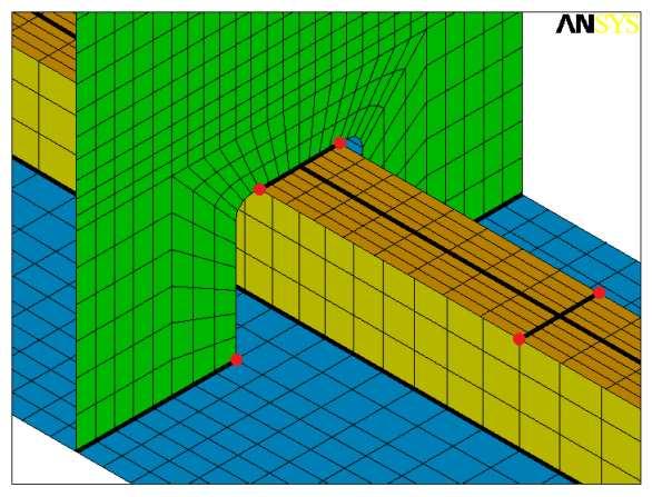
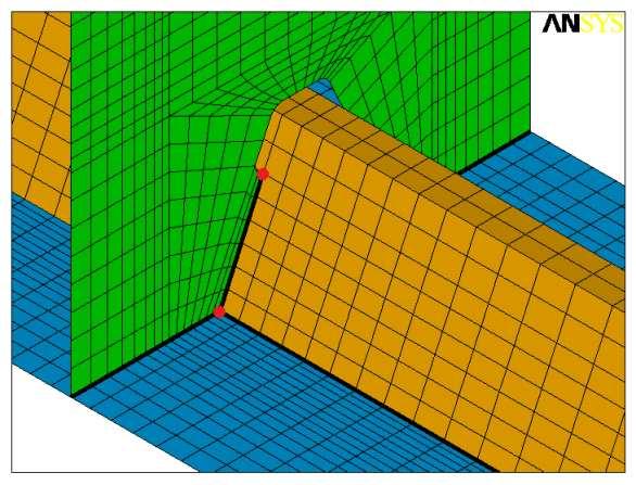
9 Motivation Some modelling considerations: Ship structure = shell plated structure Governing parameter: t b << (a,b) HOUSTON, WE HAVE A PROBLEM... Ship structure a collection of a large number and variety of fatigue prone locations, hot spots. single SN curve with stress based through-thickness criterion Shell FE environment: no weld modelling WELD LINES / basic joints / failure locations Include characteristic NOTCH crack propagation behaviour Relation to LEFM approach: welding process induced flaws exist 9 48
10 Idea Combine and extend the advantages of the different fatigue life prediction concepts for applicability in a design environment. structural (hot spot) stress concept (fictitious) notch stress concept A good scientist is a person with original ideas. nominal stress concept A good engineer is a person who makes a design(method) that works with as few original ideas as possible. TOTAL STRESS CONCEPT 10 48
11 Total Stress Concept Joint SN Curve Formulation total stress concept, T σ = 1 : total stress concept, T 10 3 σ = 1 : S R T 10 1 T-joint Butt joint Cruciform joint Longitudinal stiffener joint Gusset plate / bracket PP Butt joint LC Cruciform joint S R T 10 1 bulb st - web fr conn with bracket: type a T st - web fr conn: type c web fr - web fr conn with soft toe bracket: type a web fr - web fr conn with nested bracket: type c st - web fr conn: type b N N small scale specimen based large scale specimen fit 11 48
12 Total Stress Concept Fatigue governing parameters moving dislocations crack nucleation micro-crack propagation macro-crack propagation final fracture crack initiation crack propagation SCF SIF Stress Concentration Factor Stress Intensity Factor Welding process induced flaws already exist fracture mechanics approach (LEFM, loading mode I) Include crack initiation period modify SIF using SCF related notch stress distribution 12 48
13 Total Stress Concept Weld ends (HS type a and b) b a c c Basic welded joint formulations (HS type c): toe root DS / SS butt joint: 4x / 2x t c t b Fm t c t b Fm 2x / 1x t c DS / SS cover plate: 4x / 2x NC / NC t b t c Fm Mb t c t b Fm Mb Fm Fm t c t c DS / SS T-joint: 4x / 2x 2x / 1x t b Fm t b Fm Fm Fm t c t c DS / SS cruciform joint: 8x / 4x 4x / 2x t b Fm t b Fm Fm Fm 13 48
14 Total Stress Concept Notch stress formulation (force {F,M} induced, geometry and far field stress determined parameter): equilibrium equivalent part far field stress + self-equilibrating part weld geometry induced bending + Williams asymptotic solution mr + br = r t b F m sr
15 Total Stress Concept Notch stress formulation, force {F,M} induced: m + br Notch angle α π(fillet weld config): weld toe r t b = sr F m = + Non-symmetry w.r.t. (t b / 2), e.g. DS T-joint m + b = Symmetry w.r.t. (t b / 2), e.g. DS cruciform joint r t b s F m = + Notch angle α =π(crack config): weld root / crack growth specimen Non-symmetry, e.g. DS LC cruciform joint b b t ' b r r ' t b F m Symmetry, e.g. DEN specimen Mb 15 48
16 Total Stress Concept QUESTION 1: effects of self-equilibrating stress part Consider weld toe failure of a DS T-joint and DS cruciform joint. Will there be any difference in fatigue life and if so, which joint has a longer fatigue life? The far field stress is the same for both joints (membrane state). Please note that the nominal-, hot spot- and fict. notch stress is the same. Regarding the DS cruciform joint, consider fatigue failure from 1 side. A. Fatigue life is the same. B. DS T-joint has longer fatigue life. C. DS cruciform joint has longer fatigue life. D. There is not enough information to answer this question. r t b + r t b


: DS butt joint: DS long.")
17 Total Stress Concept Residual stress formulation (welding induced): Non-symmetry w.r.t. (t b /2): equilibrium equivalent + self-equilibrating part DS T-joint SS butt joint FE analysis, schematic Symmetry w.r.t. (t b /2): DS butt joint: DS long. stiffener: FE analysis, schematic measured [Pagel, 2011] 17 48
18 Total Stress Concept Arc-welded joint: notch stress + residual stress formulation Equilibrium equivalent part + self-equilibrating part Equilibrium equivalent part: force induced + welding induced Force induced: {F m, } Welding induced: membrane + bending (angular distortion) measured / mean stress / fatigue strength C Ss = C N 1 m measured / design value / fatigue strength C Self-equilibrating part: hypothesis: distribution is similar for notch stress and residual stress! 18 48
19 Total Stress Concept Notch stress formulation: Analytical / characteristic (near) singularity / all geometry parameters Related to linear far field stress distribution (FEM) fm m σ s = 6 t t b b 2 b R s 6 mb = 6 m t f b b m t c l w h w Example 1, (αα π), non-symmetry: DS T-joint t b F m 0.0 t c /t b = 1.0; h w /l w = 1.2; l w /t b = 1.0; ρ/t b = t c /t b = 1.0; h w /l w = 1.0; l w /t b = 1.0; ρ/t b = r/t b [ - ] r/t b [ - ] weld notch stress σ w /σ s 0.8 weld notch stress σ w /σ s 0.9 far field stress σ f /σ s FE result 0.9 far field stress σ f /σ s FE result σ w /σ s, σ f /σ s [ - ] σ w /σ s, σ f /σ s [ - ] 19 48
20 Total Stress Concept Notch stress formulation: Example 2, (α π), symmetry: DS cruciform joint t c l w h w t b F m 0.0 t c /t b = 1.0; h w /l w = 1.0; l w /t b = 1.0; ρ/t b = t c /t b = 1.0; h w /l w = 1.0; l w /t b = 0.4; ρ/t b = r/t b [ - ] weld notch stress σ w /σ s far field stress σ f /σ s FE result r/t b [ - ] weld notch stress σ w /σ s far field stress σ f /σ s FE result σ w /σ s, σ f /σ s [ - ] σ w /σ s, σ f /σ s [ - ] 20 48
, weld throat (butt joint) Stress state mainly characterised by membrane and bending as well 0.0 t c /t b = 10/10; l w /h w = 10/20; l w /t b = 10/10; a g /t b = 3/10; ρ/t b = 0/10 0.")
21 Total Stress Concept Notch stress formulation: Example 3, (α =π), non-symmetry: DS cruciform joint, SS butt joint Assumed crack path: weld leg section (cr. joint), weld throat (butt joint) Stress state mainly characterised by membrane and bending as well 0.0 t c /t b = 10/10; l w /h w = 10/20; l w /t b = 10/10; a g /t b = 3/10; ρ/t b = 0/ l w /t b = 10/8; h w /t b = 2/8; l w /h w = 10/2; a g /t b = 3/8; ρ/t b = 0/ r 1 r r '/t b ' [ - ] weld root notch stress σ wr /σ sr weld root linear stress σ lr /σ sr r 3 r '/t b ' [ - ] weld root notch stress σ wr /σ sr weld root linear stress σ lr /σ sr 1 r 2 r 3 {σ s,r s } still defines far field stress 0.9 FEM 0.9 FEM σ wr /σ sr, σ lr /σ sr [ - ] σ wr /σ sr, σ lr /σ sr [ - ] 21 48
22 Total Stress Concept Notch stress formulation: motivation Fatigue life effects: equilibrium equivalent stress part {σ s,r s } fatigue life: relative bending stress effects, far field stress only edge crack formulation centre crack formulation 0.25 s [ - ] R s N/N Rs=0 [ - ] Pure bending shows better performance compared to pure membrane: dσ dr f Non-monotonic behaviour means bad news 22 48
23 Total Stress Concept Notch stress formulation: motivation Fatigue life effects: self-equilibrating part 1.00 fatigue life: relative bending stress effects, far field stress only 1.00 fatigue life: relative bending stress effects edge crack formulation centre crack formulation non-symmetric notch behaviour symmetric notch behaviour edge crack formulation R s [ - ] 0.00 R s [ - ] answer Question 1: C N/N Rs=0 [ - ] N/N Rs(M)=0 [ - ] Non-symmetry: weld geometry induced bending part amplifies effect Symmetry: 3 criteria, bending induced anti-symmetry require shift + scaling (no far field bending stress projection) Far field bending effect counter-acted by self-equilibrating stress (notch effect) 23 48
24 Crack Propagation Model Stress Intensity Factor formulation K: generalised formulation not available for basic welded joints K I (α π), K = M Y σ π (α =π) = Y Y σ π a a m g I k g Equilibrium equivalent stress part: consistent with far field stress / solutions for simple geometries Geometry factor: Y g Self-equilibrating unit stress part: notch effect / applied as crack face pressure Magnification factor: Y m 24 48
25 Crack Propagation Model Geometry factor Y g : cracked geometry parameter Covers macro-crack effects: finite thickness (and free surface) Superposition principle: membrane + bending Y g [ sgn( F ) Y + R { sgn( F ) Y + ( M ) Y }] = sgn m gm m gm b gb Handbook solutions Weld root geometry correction M k : cracked geometry, FEM Magnification factor Y m : uncracked geometry parameter 2 π a σ ( r) Y m = dr σ ( ) 0 a 2 r 2 1 r r = σ w 2 R σ s tb r t b 25 48
26 Crack Propagation Model Stress Intensity Factor example Notch angle α π : Y m dominates (a/t b ) 0.2 Williams asympt. sol. dominates (a/t b ) 0.1 C gb dominates 0.1 < (a/t b ) 0.2 Y g dominates (a/t b ) > t c /t b = 1.0; h w /l w = 1.0; l w /t b = 1.0; ρ/t b = t c /t b = 1.0; h w /l w = 1.0; l w /t b = 1.0; ρ/t b = Y m r/t b [ - ] Y g, Y m, Y m Y g [ - ] Y g Y m Y g FEM 0.8 weld notch stress σ w /σ s far field stress σ f /σ s 0.9 FEM σ w /σ s, σ f /σ s [ - ] micro- macro-crack crack a/t b [ - ] 26 48
27 Crack Propagation Model Stress Intensity Factor example Notch angle α =π : geometry with gap a g SIF is M k Y g determined; square root notch behaviour included in K by definition M k Y g < 1, b b < t b Y m (notch effect) affects crack propagation! t c t c /t b = 10/10; l w /h w = 10/20; l w /t b = 10/10; a g /t b = 3/10; ρ/t b = 0/10 M k Y g Y m b b t ' b a g r', a r l w sr R sr s, R s h w t b F m M k Y g, Y m, ( 1/Y m ) [ - ] ( 1/Y m ) FEM a/t b ' [ - ] 27 48
28 Total Stress Concept QUESTION 2: fatigue life comparison for weld toe and weld root failure Consider a DS cruciform joint. Will there be any difference in fatigue life for the weld toe and weld root failure case and if so, which one will be longer? 5.0 t c /t b = 1.0; h w /l w = 1.0; l w /t b = 1.0; ρ/t b = t c /t b = 10/10; l w /h w = 10/10; l w /t b = 10/10; a g /t b = 5/10; ρ/t b = 0/ Y m 4.0 Y m r t b m Y g [ - ] Y m, Y g, Y m Y g Y m Y g FEM r 2a i t b M k Y g, Y m, ( 1/Y m ) [ - ] M k Y g ( 1/Y m ) FEM a/t b [ - ] a/t b ' [ - ] A. Fatigue life is the same. B. Weld root has longer fatigue life. C. Weld toe has longer fatigue life. D. There is not enough information to answer this question
29 Crack Propagation Model Characteristic da/dn- K curve (long crack growth) Paris-based two-stage model: ignore region III da dn K = C 1 K th γ ( K ) m 10-4 III K = crack driving force da/d dn 10-5 Similitude hypothesis: da/dn depends only on ( K, K th, K max, K c ) II 10-8 I 10 0 K th K K c 29 48
30 Crack Propagation Model Crack growth at NOTCHES: elasticity/plasticity 10-3 short (notch) crack growth 10-3 short (notch) crack growth (da/dn) [ mm/cycle ] long crack growth plastic short (notch) crack growth elastic short (notch) crack growth (da/dn) [ mm/cycle ] long crack growth plastic short (notch) crack growth elastic short (notch) crack growth K [ MPa mm ] K [ MPa mm ] Frost-Dugdale model: da/dn = C. a Generalised Frost-Dugdale model (Jones et. al, 2008) - non-similitude behaviour - elastic crack growth at notch da dn = C a m 1 2 ( K ) m 30 48
31 Crack Propagation Model Crack growth at NOTCHES: elasticity/plasticity P. Dong: plasticity dominated micro-crack behaviour da dn = 2 ( ) m M k K g Elasticity/plasticity criterion: r r p, notch p, crack 2 : plasticity < 2 : elasticity Model: work in progress because of slope dependency da dn ( ) m m n 2 n = 1, 2 g = C Y m K 31 48
32 Crack Propagation Model Crack growth at NOTCHES: elasticity/plasticity Example: elastic behaviour 10-2 Al 5083, T-L config Al 5083, T-L config. (da/dn) [ mm/cycle cle ] rolling direction base material; R s = -1.0 base material; R s = 0.0 (da/dn). ( Y l / Y n ) [ mm/cycle ] base material; R s = -1.0 base material; R s = K [ MPa mm ] K. ( Y l / Y n ) [ MPa mm ] 32 48
33 Crack Propagation Model Crack growth at NOTCHES: elasticity/plasticity Example: plastic behaviour incl. notch radius effects 10-2 R = 0.05 [-] 10-2 R = 0.05 [-] (da/dn) [ mm/cycle ] ρ = 0.0 [mm] ρ = 0.4 [mm] ρ = 0.7 [mm] ρ = 1.4 [mm] (da/dn) / Y 2 m [ mm/cycle cle ] ρ = 0.0 [mm] ρ = 0.4 [mm] ρ = 0.7 [mm] ρ = 1.4 [mm] K [ MPa mm ] K. ( 1/Y m ) [ MPa mm ] 33 48
34 Crack Propagation Model Crack growth at NOTCHES: Notch / micro-crack fatigue life effects and notch radius influence 0.31 micro-crack propagation fatigue life contribution 10-3 short (notch) crack growth a i [ mm ] (da/dn) [ mm/cycle ] N i /N tot [ - ] K [ MPa mm ] 34 48
35 Total Stress Concept QUESTION 3: effect of final crack length Consider a DS T-joint with SIF behaviour as shown. At what (dimensionless) crack length do you expect that > 90 [%] of the fatigue life is consumed? 5.0 t c /t b = 1.0; h w /l w = 1.0; l w /t b = 1.0; ρ/t b = short (notch) crack growth 4.5 Y m A. 0.1 (a f /t b ) B. 0.3 (a f /t b ) C. 0.5 (a f /t b ) D. 0.7 (a f /t b ) Y g, Y m, Y m Y g [ - ] 4.0 Y g Y m Y g 3.5 FEM a/t b [ - ] (da/dn) [ mm/cycle ] long crack growth plastic short (notch) crack growth elastic short (notch) crack growth K [ MPa mm ] 35 48
36 Total Stress Concept QUESTION 3: effect of final crack length Consider a DS T-joint with SIF behaviour as shown. At what (dimensionless) crack length do you expect that > 90 [%] of the fatigue life is consumed? 1.0 fatigue life: effect of final crack length N/N af=tb [ - ] A. 0.1 (a f /t b ) B. 0.3 (a f /t b ) C. 0.5 (a f /t b ) D. 0.7 (a f /t b ) a f / t b [ - ] 36 48
37 Crack Propagation Model Fatigue test results suggest a non-linear mean stress dependency. Exponential relation (Kwofie, 2001): σ σ R 1 = e σ R α σ us First order approximation: generalization of several empirical models σ σ R = 1 α σ R 1 σ us Goodman, α = 1 high-cycle fatigue: low σ / small σ R High-cycle fatigue: low σ / large σ R Walker, α = {σ us /(γ. σ R )}. ln{(1-r)/2} σ 1 = σ R 1 2 R γ 37 48
38 Crack Propagation Model σ us Walker s mean stress model using σ eff = σ e : σ σ R α σ eff = 1 superior curve fitting results: γ 0.5 for R 0 ( 1 R ) γ s γ = 0.0 for R < 0 Another definition of σ eff (Kim, Dong, 2006): σ eff = σ max σ + = + σ min mean R 0: σ eff = γ = 0.5 ( 1 R) 1 t 2 σ max R < 0: σ eff = mean γ = 0.0 ( 1 R) t Walker s model: loading dependent mean stress max min
39 Crack Propagation Model Welded joints: alternating material zones 10-2 Al 7075-T651; T-L config. Weld (filler) material Heat Affected Zone (HAZ) Base (parent) material weld HAZ base material (da/dn) [ mm/cycle ] P ~ 6 P R = R = 0.10 R = 0.50 R = 0.75 Base material, loading induced mean stress: micro- and macro crack prop. region affected according to Y m : K [ MPa mm ] 1 2 da Ym Ym = C K 1 γ 1 γ g dn ( 1 R) ( 1 R) Al 5083, T-L config Al 5083, T-L config Al 7075-T651; T-L config. m (da/dn) [ mm/cycle ] rolling direction K [ MPa mm ] R = -1.0 R = 0.0 (da/dn). ( Y l / Y n ). (1-R) 1- γ [ mm/cycle ] R = -1.0 R = K. ( Y l / Y n ) / (1-R) 1- γ [ MPa mm ] (da/dn). ( Y l / Y n ). (1-R) 1- γ [ mm/cycle ] R = R = 0.10 R = 0.50 R = K. ( Y l / Y n ) / (1-R) 1- γ [ MPa mm ] 39 48
40 Joint SN Curve Formulation Basquin type of equation: S T = C N 1 m with s and Initial crack size effect: σ ST = 2 m 1 t 2 m b I ( Rs )m I a t f a b ( R ) s = d m ai tb t b Y n m m 2 1 Y m g a t b total stress concept, T = 1 : 1.53 σ 10 3 total stress concept, T = 1 : 1.18 σ 60 initial crack size (Weibull) distribution, m = 3, µ = S R S R p [ - ] T-joint Butt joint Cruciform joint Longitudinal stiffener joint 10 1 T-joint Butt joint Cruciform joint Longitudinal stiffener joint N N a i /t b [ - ] 40 48
41 Joint SN Curve Formulation Mean stress effects: The fatigue strength of welded joints is mean stress independent. Welding induced residual stress acts as high-tensile mean stress. Micro-crack region: HAZ welding induced high-tensile residual stress dominates loading induced part Macro-crack region: base material (weld toe) / weld material (weld root) σ s ST = 1 γ 2 m 1 ( 1 R) 2 t 2 m I ( R )m b s loading induced part only in macro-crack region Weld performance improvement (technique dependent) factor R i 2 ( ) ( ) ( 1 γ ) i m ( 1 γ ) R = 1 1 R 1 R eq i micro-crack region correction and loading induced part in macro-crack region 41 48
42 Joint SN Curve Formulation Mean stress effects: 10 3 master curve formulation; T σ = 1 : master curve formulation; T σ = 1 : S s S R T-joint; R = 0.0 T-joint; R = -1.0 Butt joint; R = 0.0 Butt joint; R = -1.0 Long. stiff. joint; R = 0.1 Long. stiff. joint; R = 0.5 Long. stiff. joint; UIT N T-joint; R = 0.0 T-joint; R = -1.0 Butt joint; R = 0.0 Butt joint; R = -1.0 Long. stiff. joint; R = 0.1 Long. stiff. joint; R = 0.5 Long. stiff. joint; UIT N 42 48
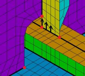
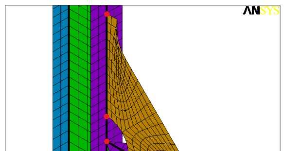
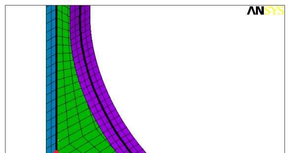
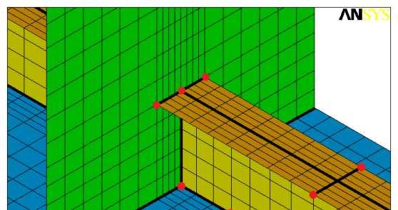
43 Joint SN Curve Formulation QUESTION 4: stress component for fatigue life calculation Consider the structural response of the stiffened panel, loaded with space averaged pressure (sea side). The welding induced residual stress is assumed to be tensile. What stress value needs to be used at Pos. 2 for fatigue life calc.? 1 ELEMENTS 1 NODAL SOLUTION 1 MN NODAL SOLUTION 1 NODAL SOLUTION REAL NUM STEP=1 STEP=1 STEP=1 SUB =1 SUB =1 SUB =1 TIME=1 TIME=1 TIME=1 2 SX (AVG) RSYS=0 DMX = SMN = SMX =37.5 SZ (AVG) RSYS=0 DMX = SMN = SMX = SEQV (AVG) DMX = SMN = SMX = Y Y MX Y Y Z X Z X Z X Z X LS specimen LS specimen LS specimen LS specimen A. σ x (mode I stress component) B. σ VM (Von Mises stress component) C. σ x (absolute value of mode I stress component) D. σ x / 2 (absolute value of half mode I stress component) 43 48
44 Joint SN Curve Formulation QUESTION 5: effect of tensile/compressive loading Assuming that the welding induced residual stress is tensile, what will be the relative mean stress ratio R w for compressive loading relative to tensile loading? σ min R = σ max s s r tension s a s max compression s min A. R w = -1 B. R w = -2 C. R w = -3 D. R w = -4 t 44 48
45 Joint SN Curve Formulation Compressive cyclic loading: SN curves data: tensile residual stress + TENSILE cyclic loading Walker model, welding induced tensile residual stress: σ σ eff = 1 ( R ) γ 1 w R γ = 0.5 Predominantly, the micro-crack propagation region is affected! Total stress parameter: region I correction answer Question 4: D σ s ST = 1 γ 2 m 1 ( 1 R) 2 t 2 m I ( R )m b s σ s σ 2 for σ < 0 for 0 ST = 1 γ 2 m 1 ( 1 R) 2 t 2 m I ( R )m b s 45 48
46 Total Stress Concept Joint SN Curve Formulation total stress concept, T σ = 1 : total stress concept, T 10 3 σ = 1 : S R T 10 1 T-joint Butt joint Cruciform joint Longitudinal stiffener joint Gusset plate / bracket PP Butt joint LC Cruciform joint S R T 10 1 bulb st - web fr conn with bracket: type a T st - web fr conn: type c web fr - web fr conn with soft toe bracket: type a web fr - web fr conn with nested bracket: type c st - web fr conn: type b N N small scale specimen based large scale specimen fit 46 48
47 Total Stress Concept QUESTION 6: effect of compressive stresses on fatigue life Consider the structural response of the stiffened panel, loaded with space averaged pressure (sea side). At what weld location is the first crack expected? The welding induced residual stress is assumed to be tensile. 1 ELEMENTS 1 NODAL SOLUTION 1 MN NODAL SOLUTION 1 NODAL SOLUTION REAL NUM STEP=1 STEP=1 STEP=1 SUB =1 SUB =1 SUB =1 TIME=1 TIME=1 TIME=1 2 SX (AVG) RSYS=0 DMX = SMN = SMX =37.5 SZ (AVG) RSYS=0 DMX = SMN = SMX = SEQV (AVG) DMX = SMN = SMX = Y Y MX Y Y Z X Z X Z X Z X LS specimen LS specimen LS specimen LS specimen A. Position 1. B. Position 2. C. Position 3. D. Position 1 and 3 Pos 1. σ z = [MPa] Pos 2. σ x = [MPa] Pos 3. σ x = 15.5 [MPa] 47 48


48 Thank you for your attention! Henk, thank you for your presentation, but... N=C S -m QUESTIONS? 48 48
V Predicted Weldment Fatigue Behavior AM 11/03 1
 V Predicted Weldment Fatigue Behavior AM 11/03 1 Outline Heavy and Light Industry weldments The IP model Some predictions of the IP model AM 11/03 2 Heavy industry AM 11/03 3 Heavy industry AM 11/03 4
D Radaj, C M Sonsino and W Pricke. Fatigue assessment of welded joints by local approaches
 D Radaj, C M Sonsino and W Pricke Fatigue assessment of welded joints by local approaches Second edition Foreword Preface Author contact details Introduction 1.1 Fatigue strength assessment of welded joints
MMJ1133 FATIGUE AND FRACTURE MECHANICS E ENGINEERING FRACTURE MECHANICS
 E ENGINEERING WWII: Liberty ships Reprinted w/ permission from R.W. Hertzberg, "Deformation and Fracture Mechanics of Engineering Materials", (4th ed.) Fig. 7.1(b), p. 6, John Wiley and Sons, Inc., 1996.
Stress concentrations, fracture and fatigue
 Stress concentrations, fracture and fatigue Piet Schreurs Department of Mechanical Engineering Eindhoven University of Technology http://www.mate.tue.nl/ piet December 1, 2016 Overview Stress concentrations
Multiaxial Fatigue. Professor Darrell F. Socie. Department of Mechanical Science and Engineering University of Illinois at Urbana-Champaign
 Multiaxial Fatigue Professor Darrell F. Socie Department of Mechanical Science and Engineering University of Illinois at Urbana-Champaign 2001-2011 Darrell Socie, All Rights Reserved Contact Information
Thermal load-induced notch stress intensity factors derived from averaged strain energy density
 Available online at www.sciencedirect.com Draft ScienceDirect Draft Draft Structural Integrity Procedia 00 (2016) 000 000 www.elsevier.com/locate/procedia 21st European Conference on Fracture, ECF21, 20-24
G1RT-CT D. EXAMPLES F. GUTIÉRREZ-SOLANA S. CICERO J.A. ALVAREZ R. LACALLE W P 6: TRAINING & EDUCATION
 D. EXAMPLES 426 WORKED EXAMPLE I Flat Plate Under Constant Load Introduction and objectives Data Analysis Bibliography/References 427 INTRODUCTION AND OBJECTIVES During a visual inspection of a C-Mn flat
Massachusetts Institute of Technology Department of Mechanical Engineering Cambridge, MA 02139
 Massachusetts Institute of Technology Department of Mechanical Engineering Cambridge, MA 02139 2.002 Mechanics and Materials II Spring 2004 Laboratory Module No. 6 Fracture Toughness Testing and Residual
JT-60 SA Toroidal Field coil structural analysis
 JT-60 SA Toroidal Field coil structural analysis Christophe Portafaix Introduction TF coil description TF coil design and electromagnetic loads Material and Criteria 2D structural analysis 3D structural
Degree of Bending in Axially Loaded Tubular KT-Joints of Offshore Structures: Parametric Study and Formulation
 Degree of Bending in Axially Loaded Tubular KT-Joints of Offshore Structures: Parametric Study and Formulation Hamid Ahmadi, Shadi Asoodeh Abstract The fatigue life of tubular joints commonly found in
Volume 2 Fatigue Theory Reference Manual
 Volume Fatigue Theory Reference Manual Contents 1 Introduction to fatigue 1.1 Introduction... 1-1 1. Description of the applied loading... 1-1.3 Endurance curves... 1-3 1.4 Generalising fatigue data...
Stress Concentration. Professor Darrell F. Socie Darrell Socie, All Rights Reserved
 Stress Concentration Professor Darrell F. Socie 004-014 Darrell Socie, All Rights Reserved Outline 1. Stress Concentration. Notch Rules 3. Fatigue Notch Factor 4. Stress Intensity Factors for Notches 5.
Laboratory 4 Bending Test of Materials
 Department of Materials and Metallurgical Engineering Bangladesh University of Engineering Technology, Dhaka MME 222 Materials Testing Sessional.50 Credits Laboratory 4 Bending Test of Materials. Objective
Lecture #7: Basic Notions of Fracture Mechanics Ductile Fracture
 Lecture #7: Basic Notions of Fracture Mechanics Ductile Fracture by Dirk Mohr ETH Zurich, Department of Mechanical and Process Engineering, Chair of Computational Modeling of Materials in Manufacturing
A novel approach to predict the growth rate of short cracks under multiaxial loadings
 A novel approach to predict the growth rate of short cracks under multiaxial loadings F. Brugier 1&2, S. Pommier 1, R. de Moura Pinho 2, C. Mary 2 and D. Soria 2 1 LMT-Cachan, ENS Cachan / CNRS / UPMC
Finite Element Investigation on the Stress State at Crack Tip by Using EPFM Parameters
 Finite Element Investigation on the Stress State at Crack Tip by Using EPFM Parameters FRANCESCO CAPUTO, ALESSANDRO DE LUCA, GIUSEPPE LAMANNA 1, ALESSANDRO SOPRANO Department of Industrial and Information
A STUDY ON FATIGUE CRACK GROWTH IN CONCRETE IN THE PRE-PARIS REGION
 VIII International Conference on Fracture Mechanics of Concrete and Concrete Structures FraMCoS-8 J.G.M. Van Mier, G. Ruiz, C. Andrade, R.C. Yu and X.X. Zhang (Eds) A STUDY ON FATIGUE CRACK GROWTH IN CONCRETE
Fatigue and Fracture
 Fatigue and Fracture Multiaxial Fatigue Professor Darrell F. Socie Mechanical Science and Engineering University of Illinois 2004-2013 Darrell Socie, All Rights Reserved When is Multiaxial Fatigue Important?
Stress Intensity Factor Determination of Multiple Straight and Oblique Cracks in Double Cover Butt Riveted Joint
 ISSN (Online) : 2319-8753 ISSN (Print) : 2347-671 International Journal of Innovative Research in Science, Engineering and Technology Volume 3, Special Issue 3, March 214 214 International Conference on
Load Sequence Interaction Effects in Structural Durability
 Load Sequence Interaction Effects in Structural Durability M. Vormwald 25. Oktober 200 Technische Universität Darmstadt Fachgebiet Werkstoffmechanik Introduction S, S [ log] S constant amplitude S variable
Burst pressure estimation of reworked nozzle weld on spherical domes
 Indian Journal of Engineering & Materials Science Vol. 21, February 2014, pp. 88-92 Burst pressure estimation of reworked nozzle weld on spherical domes G Jegan Lal a, Jayesh P a & K Thyagarajan b a Cryo
Determination of Stress Intensity Factor for a Crack Emanating From a Rivet Hole and Approaching Another in Curved Sheet
 International OPEN ACCESS Journal Of Modern Engineering Research (IJMER) Determination of Stress Intensity Factor for a Crack Emanating From a Rivet Hole and Approaching Another in Curved Sheet Raghavendra.
This guide is made for non-experienced FEA users. It provides basic knowledge needed to start your fatigue calculations quickly.
 Quick Fatigue Analysis Guide This guide is made for non-experienced FEA users. It provides basic knowledge needed to start your fatigue calculations quickly. Experienced FEA analysts can also use this
Variation of Stress Range Due to Variation in Sea States An Overview of Simplified Method of Fatigue Analysis of Fixed Jacket Offshore Structure
 American Journal of Engineering Research (AJER) e-issn : 2320-0847 p-issn : 2320-0936 Volume-03, Issue-04, pp-98-107 www.ajer.org Research Paper Open Access Variation of Due to Variation in Sea States
Critical applied stresses for a crack initiation from a sharp V-notch
 Focussed on: Fracture and Structural Integrity related Issues Critical applied stresses for a crack initiation from a sharp V-notch L. Náhlík, P. Hutař Institute of Physics of Materials, Academy of Sciences
IMECE CRACK TUNNELING: EFFECT OF STRESS CONSTRAINT
 Proceedings of IMECE04 2004 ASME International Mechanical Engineering Congress November 13-20, 2004, Anaheim, California USA IMECE2004-60700 CRACK TUNNELING: EFFECT OF STRESS CONSTRAINT Jianzheng Zuo Department
PLATE GIRDERS II. Load. Web plate Welds A Longitudinal elevation. Fig. 1 A typical Plate Girder
 16 PLATE GIRDERS II 1.0 INTRODUCTION This chapter describes the current practice for the design of plate girders adopting meaningful simplifications of the equations derived in the chapter on Plate Girders
Elastic and Elastic-Plastic Behaviour of a Crack in a Residual Stress Field
 Residual Stresses 2016: IC-10 Elastic and Elastic-Plastic Behaviour of a Crack in a Residual Stress Field Guiyi Wu a, Chris Aird b, David Smith and Martyn Pavier c* Department of Mechanical Engineering,
5 ADVANCED FRACTURE MODELS
 Essentially, all models are wrong, but some are useful George E.P. Box, (Box and Draper, 1987) 5 ADVANCED FRACTURE MODELS In the previous chapter it was shown that the MOR parameter cannot be relied upon
Topics in Ship Structures
 Topics in Ship Structures 8 Elastic-lastic Fracture Mechanics Reference : Fracture Mechanics by T.L. Anderson Lecture Note of Eindhoven University of Technology 17. 1 by Jang, Beom Seon Oen INteractive
Durability of bonded aircraft structure. AMTAS Fall 2016 meeting October 27 th 2016 Seattle, WA
 Durability of bonded aircraft structure AMTAS Fall 216 meeting October 27 th 216 Seattle, WA Durability of Bonded Aircraft Structure Motivation and Key Issues: Adhesive bonding is a key path towards reduced
DEVELOPMENT OF TEST GUIDANCE FOR COMPACT TENSION FRACTURE TOUGHNESS SPECIMENS CONTAINING NOTCHES INSTEAD OF FATIGUE PRE-CRACKS
 Transactions, SMiRT-23 Division II, Paper ID 287 Fracture Mechanics and Structural Integrity DEVELOPMENT OF TEST GUIDANCE FOR COMPACT TENSION FRACTURE TOUGHNESS SPECIMENS CONTAINING NOTCHES INSTEAD OF
Tensile behaviour of anti-symmetric CFRP composite
 Available online at www.sciencedirect.com Procedia Engineering 1 (211) 1865 187 ICM11 Tensile behaviour of anti-symmetric CFRP composite K. J. Wong a,b, *, X. J. Gong a, S. Aivazzadeh a, M. N. Tamin b
Influence of column web stiffening on the seismic behaviour of beam-tocolumn
 Influence of column web stiffening on the seismic behaviour of beam-tocolumn joints A.L. Ciutina & D. Dubina The Politehnica University of Timisoara, Romania ABSTRACT: The present paper summarises the
Weld Fracture. How Residual Stresses Affect Prediction of Brittle Fracture. Outline. Residual Stress in Thick Welds
 How Residual Stresses ffect Prediction of Brittle Fracture Michael R. Hill University of California, Davis Tina L. Panontin NS-mes Research Center Weld Fracture Defects provide location for fracture initiation
A Model for Local Plasticity Effects on Fatigue Crack Growth
 A Model for Local Plasticity Effects on Fatigue Crack Growth USAF Aircraft Structural Integrity Program Conference San Antonio, Texas November 28-30, 2006 R. Craig McClung Brian M. Gardner Yi-Der Lee Fraser
University of Sheffield The development of finite elements for 3D structural analysis in fire
 The development of finite elements for 3D structural analysis in fire Chaoming Yu, I. W. Burgess, Z. Huang, R. J. Plank Department of Civil and Structural Engineering StiFF 05/09/2006 3D composite structures
Stress concentration factor in plates with transverse butt-weld misalignment
 Journal of Constructional Steel Research 52 (1999) 159 170 www.elsevier.com/locate/jcsr Stress concentration factor in plates with transverse butt-weld misalignment Weicheng Cui a,*, Zhengquan Wan b, Alaa
FCP Short Course. Ductile and Brittle Fracture. Stephen D. Downing. Mechanical Science and Engineering
 FCP Short Course Ductile and Brittle Fracture Stephen D. Downing Mechanical Science and Engineering 001-015 University of Illinois Board of Trustees, All Rights Reserved Agenda Limit theorems Plane Stress
Stress and Displacement Analysis of a Rectangular Plate with Central Elliptical Hole
 Stress and Displacement Analysis of a Rectangular Plate with Central Elliptical Hole Dheeraj Gunwant, J. P. Singh mailto.dheerajgunwant@gmail.com, jitenderpal2007@gmail.com, AIT, Rampur Abstract- A static
FME461 Engineering Design II
 FME461 Engineering Design II Dr.Hussein Jama Hussein.jama@uobi.ac.ke Office 414 Lecture: Mon 8am -10am Tutorial Tue 3pm - 5pm 10/1/2013 1 Semester outline Date Week Topics Reference Reading 9 th Sept 1
Prediction of Elastic-Plastic Behaviour of Structures at Notches
 Prediction of Elastic-Plastic Behaviour of Structures at Notches TANWEER HUSSAIN*, MUJEEBUDDIN MEMON**, AND ZEESHAN ALI MEMON*** RECEIVED ON 01.05.2012 ACCEPTED ON 21.06.2012 ABSTRACT Under the condition
Elastic-Plastic Fracture Mechanics. Professor S. Suresh
 Elastic-Plastic Fracture Mechanics Professor S. Suresh Elastic Plastic Fracture Previously, we have analyzed problems in which the plastic zone was small compared to the specimen dimensions (small scale
Fracture Behavior. Section
 Section 6 Fracture Behavior In January 1943 the one-day old Liberty Ship, SS Schenectady, had just completed successful sea trials and returned to harbor in calm cool weather when... "Without warning and
FE-Analysis of Stringer-to-floor-beam Connections in Riveted Railway Bridges
 FE-Analysis of Stringer-to-floor-beam Connections in Riveted Railway Bridges By Mohammad Al-Emrani 1 and Robert Kliger 2 Department of Structural Engineering Chalmers University of Technology, SE-412 96
MODIFIED MONTE CARLO WITH LATIN HYPERCUBE METHOD
 MODIFIED MONTE CARLO WITH LATIN HYPERCUBE METHOD Latin hypercube sampling (LHS) was introduced by McKay, Conover and Beckman as a solution to increase the efficiency of computer simulations. This technique
Fracture mechanics fundamentals. Stress at a notch Stress at a crack Stress intensity factors Fracture mechanics based design
 Fracture mechanics fundamentals Stress at a notch Stress at a crack Stress intensity factors Fracture mechanics based design Failure modes Failure can occur in a number of modes: - plastic deformation
MMJ1133 FATIGUE AND FRACTURE MECHANICS A - INTRODUCTION INTRODUCTION
 A - INTRODUCTION INTRODUCTION M.N.Tamin, CSMLab, UTM Course Content: A - INTRODUCTION Mechanical failure modes; Review of load and stress analysis equilibrium equations, complex stresses, stress transformation,
Estimation of Fatigue Life of Welded Joint Using Vibration-Fatigue Computational Model
 Estimation of Fatigue Life of Welded Joint Using Vibration-Fatigue Computational Model By Eniyavan Subramanian A thesis submitted to the Faculty of Graduate Studies in partial fulfilment of the requirements
Review of the Master SN Neuber Rule in the ASME Division 2 Rewrite Project
 Review of the Master SN Neuber Rule in the ASME Division 2 Rewrite Project ASME BPVC Code Week Atlanta, GA February 2007 Chris Hinnant Paulin Research Group Houston, TX Table of Contents 1.0 Introduction
Transactions on Modelling and Simulation vol 9, 1995 WIT Press, ISSN X
 Elastic-plastic model of crack growth under fatigue using the boundary element method M. Scibetta, O. Pensis LTAS Fracture Mechanics, University ofliege, B-4000 Liege, Belgium Abstract Life of mechanic
Rules for Classification and Construction Analysis Techniques
 V Rules for Classification and Construction Analysis Techniques 1 Hull Structural Design Analyses 2 Guidelines for Fatigue Strength Analyses of Ship Structures Edition 2004 The following Guidelines come
Treatment of Constraint in Non-Linear Fracture Mechanics
 Treatment of Constraint in Non-Linear Fracture Mechanics Noel O Dowd Department of Mechanical and Aeronautical Engineering Materials and Surface Science Institute University of Limerick Ireland Acknowledgements:
Effective stress assessment at rectangular rounded lateral notches
 Focussed on characterization of crack tip fields Effective stress assessment at rectangular rounded lateral notches Enrico Maggiolini, Roberto Tovo, Paolo Livieri University of Ferrara Enrico.maggiolini@unife.it,
NUMERICAL INVESTIGATION AND STATISTICAL ANALYSIS OF LASER BENDING OF TITANIUM SHEETS
 5 th International & 26 th All India Manufacturing Technology, Design and Research Conference (AIMTDR 2014) December 12 th 14 th, 2014, IIT Guwahati, Assam, India NUMERICAL INVESTIGATION AND STATISTICAL
FRACTURE MECHANICS FOR MEMBRANES
 FRACTURE MECHANICS FOR MEMBRANES Chong Li, Rogelio Espinosa and Per Ståhle Solid Mechanics, Malmö University SE 205 06 Malmö, Sweden chong.li@ts.mah.se Abstract During fracture of membranes loading often
Damage accumulation model for aluminium-closed cell foams subjected to fully reversed cyclic loading
 Fatigue & Fracture of Engineering Materials & Structures doi: 10.1111/j.1460-2695.2011.01591.x Damage accumulation model for aluminium-closed cell foams subjected to fully reversed cyclic loading H. PINTO
For ASME Committee use only.
 ð15þ KD-232 PROTECTION AGAINST LOCAL FAILURE In addition to demonstrating protection against plastic collapse as defined in KD-231, the local failure criteria below shall be satisfied. KD-232.1 Elastic
Fracture Mechanics, Damage and Fatigue Non Linear Fracture Mechanics: J-Integral
 University of Liège Aerospace & Mechanical Engineering Fracture Mechanics, Damage and Fatigue Non Linear Fracture Mechanics: J-Integral Ludovic Noels Computational & Multiscale Mechanics of Materials CM3
Fatigue calculations in ANSYS Workbench. Martin Eerme
 Fatigue calculations in ANSYS Workbench Martin Eerme What is fatigue? In materials science, fatigue is the progressive and localized structural damage that occurs when a material is subjected to cyclic
A PROCEDURE TO OBTAIN THE PROBABILISTIC KITAGAWA-TAKAHASHI DIAGRAM
 U.P.B. Sci. Bull., Series D, Vol. 78, Iss. 1, 2016 ISSN 1454-2358 A PROCEDURE TO OBTAIN THE PROBABILISTIC KITAGAWA-TAKAHASHI DIAGRAM José A.F.O. CORREIA 1, Abílio M.P. De JESUS 2, Alfonso Fernández- CANTELI
5. STRESS CONCENTRATIONS. and strains in shafts apply only to solid and hollow circular shafts while they are in the
 5. STRESS CONCENTRATIONS So far in this thesis, most of the formulas we have seen to calculate the stresses and strains in shafts apply only to solid and hollow circular shafts while they are in the elastic
Stress Concentrations, Fatigue, Fracture
 Stress Concentrations, Fatigue, Fracture The fundamental topic in this document is the development of cracks in steel. For structures subjected to cyclic loads, such cracks can develop over time and ultimately
Crack Tip Plastic Zone under Mode I Loading and the Non-singular T zz -stress
 Crack Tip Plastic Zone under Mode Loading and the Non-singular T -stress Yu.G. Matvienko Mechanical Engineering Research nstitute of the Russian Academy of Sciences Email: ygmatvienko@gmail.com Abstract:
Evolution of Tenacity in Mixed Mode Fracture Volumetric Approach
 Mechanics and Mechanical Engineering Vol. 22, No. 4 (2018) 931 938 c Technical University of Lodz Evolution of Tenacity in Mixed Mode Fracture Volumetric Approach O. Zebri LIDRA Laboratory, Research team
Tentamen/Examination TMHL61
 Avd Hållfasthetslära, IKP, Linköpings Universitet Tentamen/Examination TMHL61 Tentamen i Skademekanik och livslängdsanalys TMHL61 lördagen den 14/10 2000, kl 8-12 Solid Mechanics, IKP, Linköping University
THE PISA CODE. Roberta Lazzeri Department of Aerospace Engineering Pisa University Via G. Caruso, Pisa, Italy
 3/2 THE PISA CODE Roberta Lazzeri Department of Aerospace Engineering Pisa University Via G. Caruso, 56122 Pisa, Italy Abstract. A numerical model to simulate the fatigue behaviour of typical aeronautical
Stress Analysis of a Compressor Vane-Spring
 Purdue University Purdue e-pubs International Compressor Engineering Conference School of Mechanical Engineering 1994 Stress Analysis of a Compressor Vane-Spring K. T. Ooi Nanyang Technological University
A Crack Growth Rate Conversion Module: Theory, Development, User Guide and Examples
 A Crack Growth Rate Conversion Module: Theory, Development, User Guide and Examples Yu Chee Tong, Weiping Hu and David Mongru Air Vehicles Division Defence Science and Technology Organisation DSTO-TR-2050
ACDC. User Manual. Ver. 1.0
 ACDC User Manual Ver. 1.0 Centre Composite December 2016 ACDC, Ver. 1.0 User Manual Centre Composite, 2016 (software@composite.lv) Table of Contents Introduction... 1 System requirements... 1 Theoretical
Predicting Fatigue Life with ANSYS Workbench
 Predicting Fatigue Life with ANSYS Workbench How To Design Products That Meet Their Intended Design Life Requirements Raymond L. Browell, P. E. Product Manager New Technologies ANSYS, Inc. Al Hancq Development
FRACTURE IN HIGH PERFORMANCE FIBRE REINFORCED CONCRETE PAVEMENT MATERIALS
 FRACTURE IN HIGH PERFORMANCE FIBRE REINFORCED CONCRETE PAVEMENT MATERIALS ERIK DENNEMAN A thesis submitted in partial fulfilment of the requirements for the degree of PHILOSOPHIAE DOCTOR (ENGINEERING)
INFLUENCE OF HYDROSTATIC PRESSURE ON MULTIAXIAL FATIGUE OF NOTCHED COMPONENTS. G. Qilafku, G. Pluvinage
 ICF 1729OR INFLUENCE OF HYDROSTATIC PRESSURE ON MULTIAXIAL FATIGUE OF NOTCHED COMPONENTS G. Qilafku, G. Pluvinage Laboratoire de Fiabilité Mécanique, Université de Metz, France ABSTRACT: Tests have been
RESIDUAL STRESS MEASUREMENT IN STEEL BEAMS USING THE INCREMENTAL SLITTING TECHNIQUE
 659 RESIDUAL STRESS MEASUREMENT IN STEEL BEAMS USING THE INCREMENTAL SLITTING TECHNIQUE DZL Hodgson 1, DJ Smith 1, A Shterenlikht 1 1 Department of Mechanical Engineering, University of Bristol University
FATIGUE STRENGTH ANALYSIS OF STEEL HULL STRUCTURE
 RULES PUBLICATION NO. 45/P FATIGUE STRENGTH ANALYSIS OF STEEL HULL STRUCTURE 1998 Publications P (Additional Rule Requirements) issued by Polski Rejestr Statków complete or extend the Rules and are mandatory
FINITE ELEMENT ANALYSIS OF TAPERED COMPOSITE PLATE GIRDER WITH A NON-LINEAR VARYING WEB DEPTH
 Journal of Engineering Science and Technology Vol. 12, No. 11 (2017) 2839-2854 School of Engineering, Taylor s University FINITE ELEMENT ANALYSIS OF TAPERED COMPOSITE PLATE GIRDER WITH A NON-LINEAR VARYING
INFLUENCE OF A WELDED PIPE WHIP RESTRAINT ON THE CRITICAL CRACK SIZE IN A 90 BEND
 18th International Conference on Structural Mechanics in Reactor Technology (SMiRT 18) Beijing, China, August 7-12, 25 SMiRT18-G8-5 INFLUENCE OF A WELDED PIPE WHIP RESTRAINT ON THE CRITICAL CRACK SIZE
 http://www.diva-portal.org This is the published version of a paper presented at Int. Conf. on Structural Safety and Reliability (ICOSSAR) 2th International Conference on Structural Safety and Reliability
Geometric and Material Property Effects on the Strength of Rubber-Toughened Adhesive Joints
 Geometric and Material Property Effects on the Strength of Rubber-Toughened Adhesive Joints Altering the geometry of a bonded joint will invariably cause changes to occur in the stress and strain distribution
Introduction to Fracture
 Introduction to Fracture Introduction Design of a component Yielding Strength Deflection Stiffness Buckling critical load Fatigue Stress and Strain based Vibration Resonance Impact High strain rates Fracture
Linear Elastic Fracture Mechanics
 Measure what is measurable, and make measurable what is not so. - Galileo GALILEI Linear Elastic Fracture Mechanics Krishnaswamy Ravi-Chandar Lecture presented at the University of Pierre and Marie Curie
NTNU Faculty of Engineering Science and Technology Department of Marine Technology TMR 4195 DESIGN OF OFFSHORE STRUCTURES
 NTNU Faculty of Engineering Science and Technology Department of Marine Technology EXERCISE 4 TMR 495 DESIGN OF OFFSHORE STRUCTURES Distr. Date: 9 th Feb 4 Sign: Q. Chen Mandatory Exercise This exercise
Table of Contents. Preface...xvii. Part 1. Level
 Preface...xvii Part 1. Level 1... 1 Chapter 1. The Basics of Linear Elastic Behavior... 3 1.1. Cohesion forces... 4 1.2. The notion of stress... 6 1.2.1. Definition... 6 1.2.2. Graphical representation...
Examination in Damage Mechanics and Life Analysis (TMHL61) LiTH Part 1
 LiTH Part 1") Part 1 1. (1p) Define the Kronecker delta and explain its use. The Kronecker delta δ ij is defined as δ ij = 0 if i j 1 if i = j and it is used in tensor equations to include (δ ij = 1) or "sort out" (δ
Part 1 1. (1p) Define the Kronecker delta and explain its use. The Kronecker delta δ ij is defined as δ ij = 0 if i j 1 if i = j and it is used in tensor equations to include (δ ij = 1) or "sort out" (δ
COURSE TITLE : APPLIED MECHANICS & STRENGTH OF MATERIALS COURSE CODE : 4017 COURSE CATEGORY : A PERIODS/WEEK : 6 PERIODS/ SEMESTER : 108 CREDITS : 5
 COURSE TITLE : APPLIED MECHANICS & STRENGTH OF MATERIALS COURSE CODE : 4017 COURSE CATEGORY : A PERIODS/WEEK : 6 PERIODS/ SEMESTER : 108 CREDITS : 5 TIME SCHEDULE MODULE TOPICS PERIODS 1 Simple stresses
Fracture Mechanics, Damage and Fatigue Linear Elastic Fracture Mechanics - Energetic Approach
 University of Liège Aerospace & Mechanical Engineering Fracture Mechanics, Damage and Fatigue Linear Elastic Fracture Mechanics - Energetic Approach Ludovic Noels Computational & Multiscale Mechanics of
EDEM DISCRETIZATION (Phase II) Normal Direction Structure Idealization Tangential Direction Pore spring Contact spring SPRING TYPES Inner edge Inner d
 Normal Direction Structure Idealization Tangential Direction Pore spring Contact spring SPRING TYPES Inner edge Inner d") Institute of Industrial Science, University of Tokyo Bulletin of ERS, No. 48 (5) A TWO-PHASE SIMPLIFIED COLLAPSE ANALYSIS OF RC BUILDINGS PHASE : SPRING NETWORK PHASE Shanthanu RAJASEKHARAN, Muneyoshi
Institute of Industrial Science, University of Tokyo Bulletin of ERS, No. 48 (5) A TWO-PHASE SIMPLIFIED COLLAPSE ANALYSIS OF RC BUILDINGS PHASE : SPRING NETWORK PHASE Shanthanu RAJASEKHARAN, Muneyoshi
INFLUENCE OF THE LOCATION AND CRACK ANGLE ON THE MAGNITUDE OF STRESS INTENSITY FACTORS MODE I AND II UNDER UNIAXIAL TENSION STRESSES
 INFLUENCE OF THE LOCATION AND CRACK ANGLE ON THE MAGNITUDE OF STRESS INTENSITY FACTORS MODE I AND II UNDER UNIAXIAL TENSION STRESSES Najah Rustum Mohsin Southern Technical University, Technical Institute-Nasiriya,
Presented by: Civil Engineering Academy
 Presented by: Civil Engineering Academy Structural Design and Material Properties of Steel Presented by: Civil Engineering Academy Advantages 1. High strength per unit length resulting in smaller dead
NONLINEAR LOCAL BENDING RESPONSE AND BULGING FACTORS FOR LONGITUDINAL AND CIRCUMFERENTIAL CRACKS IN PRESSURIZED CYLINDRICAL SHELLS
 NONINEAR OA BENDING RESPONSE AND BUGING FATORS FOR ONGITUDINA AND IRUMFERENTIA RAKS IN PRESSURIZED YINDRIA SHES Richard D. Young, * heryl A. Rose, * and James H. Starnes, Jr. NASA angley Research enter
Accelerated Testing Methodology for Long Term Durability of CFRP
 IFREMER-ONR Workshop on Durability of Composites in a Marine Environment August 23 24, 22 IFREMER Centre, Nantes, France Accelerated esting Methodology for Long erm Durability of CFRP Masayuki Nakada*,
Analysis of local stress concentration at transitions
 Analysis of local stress concentration at transitions ESIS TC24 Meeting 1-2 October, 2014, POLIMI (Milano) Aitor Landaberea CAF S.A. Wheels, Axles and Gearboxes Business Unit Contents Introduction Axle
Part :Fill the following blanks (20 points)
") Part :Fill the following blanks (20 points) 1. Among the impurity elements in carbon steel, ( ) are useful elements, ( ) are harmful elements. 2. The plastic properties of metal materials are ( ) and 3.
Part :Fill the following blanks (20 points) 1. Among the impurity elements in carbon steel, ( ) are useful elements, ( ) are harmful elements. 2. The plastic properties of metal materials are ( ) and 3.
Deterministic and stochastic investigation of welded, high strength steel T joint
 Szakály Ferenc Student, MSc in Computational Structural Engineering, BUTE (M.Sc.) Deterministic and stochastic investigation of welded, high strength steel T joint Scientific Student s Association Thesis
Non-linear fracture mechanics in LS-DYNA and LS-PrePost
 Non-linear fracture mechanics in LS-DYNA and LS-PrePost Per Lindström 1,, Anders Jonsson 3, Anders Jernberg 3, Erling Østby 1 Department of Engineering Science, University West, Trollhättan, Sweden DNV
NUMERICAL INVESTIGATION OF THE LOAD CARRYING CAPACITY OF LAMINATED VENEER LUMBER (LVL) JOISTS WITH HOLES
 JOISTS WITH HOLES") NUMERICAL INVESTIGATION OF THE LOAD CARRYING CAPACITY OF LAMINATED VENEER LUMBER (LVL) JOISTS WITH HOLES Manoochehr Ardalany 1, Bruce L. Deam 2, Massimo Fragiacomo 3 ABSTRACT: Predicting the load carrying
NUMERICAL INVESTIGATION OF THE LOAD CARRYING CAPACITY OF LAMINATED VENEER LUMBER (LVL) JOISTS WITH HOLES Manoochehr Ardalany 1, Bruce L. Deam 2, Massimo Fragiacomo 3 ABSTRACT: Predicting the load carrying
Reliability analysis of different structure parameters of PCBA under drop impact
 Journal of Physics: Conference Series PAPER OPEN ACCESS Reliability analysis of different structure parameters of PCBA under drop impact To cite this article: P S Liu et al 2018 J. Phys.: Conf. Ser. 986
Ultimate shear strength of FPSO stiffened panels after supply vessel collision
 Ultimate shear strength of FPSO stiffened panels after supply vessel collision Nicolau Antonio dos Santos Rizzo PETROBRAS Rio de Janeiro Brazil Marcelo Caire SINTEF do Brasil Rio de Janeiro Brazil Carlos
Basics of Finite Element Analysis. Strength of Materials, Solid Mechanics
 Basics of Finite Element Analysis Strength of Materials, Solid Mechanics 1 Outline of Presentation Basic concepts in mathematics Analogies and applications Approximations to Actual Applications Improvisation
MATERIAL MECHANICS, SE2126 COMPUTER LAB 2 PLASTICITY
 MATERIAL MECHANICS, SE2126 COMPUTER LAB 2 PLASTICITY PART A INTEGRATED CIRCUIT An integrated circuit can be thought of as a very complex maze of electronic components and metallic connectors. These connectors