FME461 Engineering Design II
|
|
|
- Russell Weaver
- 5 years ago
- Views:
Transcription
1 FME461 Engineering Design II Dr.Hussein Jama Office 414 Lecture: Mon 8am -10am Tutorial Tue 3pm - 5pm 10/1/2013 1
2 Semester outline Date Week Topics Reference Reading 9 th Sept 1 House keeping issues Introduction to mechanical design Assignment 1 is given out Ch 1 - Norton, Shigley 16 th Sept 23 rd Sept 2 Ethics & safety Various 3 Assignment 1 is due Assignment 2 is given out Static & Fatigue Failure Various Ch 5 Shigley Ch 6 Shigley 30 th 4 FMEA Various Sept 7 th Oct 5 Continuous Assessment Test 1 (15%) Assignment 2 is due Assignment 3 is given out 14 th Oct 6 Shafts and shaft components Ch 7 Shigley 21 st Oct 7 Welding and permanent joints Ch 9 Shigley 28 th Oct 8 Mechanical springs Ch 10 Shigley 4 th Nov 9 Clutches & brakes Ch 16 Shigley 11 th Nov 10 Belts and chains Ch 17 Shigley 18 th Nov 11 Statistical consideration Ch 20 Shigley 25 th Nov 12 Continuous Assessment Test 2 (15%) 10/1/ nd Dec 13 Presentation of assignment 2 Assignment 2 is due
3 Discussion Shigley Chapter 5 - Static failure criteria Ductile materials Brittle materials Shigley Chapter 6 Fatigue failure criteria 10/1/2013 3
4 Static & Fatigue Failure Static load a stationary load that is gradually applied having an unchanging magnitude and direction Failure A part is permanently distorted and will not function properly A part has been separated into two or more pieces. 10/1/2013 4
5 Static failure theories Maximum shear Stress theory Distortion energy theory Ductile Coulomb-Mohr theory 10/1/2013 5
6 Definitions Material Strength S y = Yield strength in tension, S yt = S yc S ys = Yield strength in shear S u = Ultimate strength in tension, S ut S uc = Ultimate strength in compression S us = Ultimate strength in shear =.67 S u 10/1/2013 6
7 Ductile and brittle materials A ductile material deforms significantly before fracturing. Ductility is measured by % elongation at the fracture point. Materials with 5% or more elongation are considered ductile. Brittle material yields very little before fracturing, the yield strength is approximately the same as the ultimate strength in tension. The ultimate strength in compression is much larger than the ultimate strength in tension. 10/1/2013 7
 component < S y 2 = S y max = S y 2 n n = Safety factor 10/1/2013 8 =S y Design")
8 Failure theories Ductile materials Maximum shear stress theory (Tresca 1886) ( ma specimen of the same material when that specimen x ) component > ( ) obtained from a tension test at the yield point Failure = S y To avoid failure = S y 2 ( max ) component < S y 2 = S y max = S y 2 n n = Safety factor 10/1/ =S y Design equation
9 Max. Shear Theory The maximum-shear-stress theory predicts that yielding begins whenever the maximum shear stress in any element equals or exceeds the maximum shear stress in a tension test. 10/1/2013 9
10 Failure theories Ductile materials Distortion energy theory (von Mises-Hencky) Simple tension test (S y ) t Hydrostatic state of stress (S y ) h t (S y ) h >> (S y ) t h Distortion contributes to failure much more than change in volume. h h t (total strain energy) (strain energy due to hydrostatic stress) = strain energy due to angular distortion > strain energy obtained from a tension test at the yield point failure 10/1/

11 Plane stress problems 10/1/

12 Stress components 10/1/

13 Failure theories ductile materials The area under the curve in the elastic region is called the Elastic Strain Energy. U = ½ ε 3D case U T = ½ 1 ε 1 + ½ 2 ε 2 + ½ 3 ε 3 Stress-strain relationship ε 1 = 1 E v 2 E v 3 E ε 2 = 2 E v 1 E v 3 E ε 3 = E v 3 1 E v 2 E 1 U T = ( ) - 2v ( ) 2E 10/1/
14 Failure theories Ductile materials Distortion strain energy = total strain energy hydrostatic strain energy 1 U d = U T U h U T = ( ) - 2v ( ) 2E (1) Substitute 1 = 2 = 3 = h U h = ( h + h + 2 h ) - 2v ( h h + h h+ h h) 2E Simplify and substitute = 3 h into the above equation 2 3 h U h = (1 2v) = 2E U d = U T U h = 6E ( ) 2 (1 2v) Subtract the hydrostatic strain energy from the total energy to obtain the distortion energy 1 + v 10/1/ E ( 1 2 ) 2 + ( 1 3 ) 2 + ( 2 3 ) 2 (2)
15 Failure theories Ductile materials Strain energy from a tension test at the yield point 1 = S y and 2 = 3 = 0 Substitute in equation (2) U d = U T U h = 1 + v 6E ( 1 2 ) 2 + ( 1 3 ) 2 + ( 2 3 ) 2 U test = (S y ) v 3E To avoid failure, U d < U test ( 1 2 ) 2 + ( 1 3 ) 2 + ( 2 3 ) 2 2 ½ < S y 10/1/
16 Failure theories ductile materials ( 1 2 ) 2 + ( 1 3 ) 2 + ( 2 3 ) 2 2 ½ < S y 2D case, 3 = 0 ( 1 ½ ) < S y = Where is von Mises stress = S y n Design equation 10/1/
17 Failure theories -Ductile materials Pure torsion, = 1 = 2 ( ) = S y = S y 2 S ys = S y / 3 S ys =.577 S y Relationship between yield strength in tension and shear If y = 0, then 1, 2 = x/2 [( x )/2] 2 + ( xy ) 2 the design equation can be written in terms of the dominant component stresses (due to bending and torsion) ( x) 2 + 3( xy ) 2 S y = n 10/1/ /2
18 Summary Ductile materials 10/1/
19 Design process Distortion energy theory Maximum shear stress theory S y S y = max = n 2n Select material: consider environment, density, availability S y, S u Choose a safety factor n Size Weight Cost The selection of an appropriate safety factor should be based on the following: Degree of uncertainty about loading (type, magnitude and direction) Degree of uncertainty about material strength Uncertainties related to stress analysis Consequence of failure; human safety and economics Type of manufacturing process Codes and standards 10/1/
20 Flow process 10/1/
21 Design Process Use n = 1.2 to 1.5 for reliable materials subjected to loads that can be determined with certainty. Use n = 1.5 to 2.5 for average materials subjected to loads that can be determined. Also, human safety and economics are not an issue. Use n = 3.0 to 4.0 for well known materials subjected to uncertain loads. 10/1/
22 Design Process Select material, consider environment, density, availability S y, S u Choose a safety factor Formulate the von Mises or maximum shear stress in terms of size. Use appropriate failure theory to calculate the size. = S y n max = S y 2n Optimize for weight, size, or cost. 10/1/


23 Example from Shigley 10/1/

24 Solution 10/1/
25 Failure theories- brittle materials One of the characteristics of a brittle material is that the ultimate strength in compression is much larger than ultimate strength in tension. S uc >> S ut Mohr s circles for compression and tension tests. S uc 3 Stress 1 state S ut Compression test Tension test Failure envelope The component is safe if the state of stress falls inside the failure envelope. 1 > 3 and 2 = 0 10/1/
26 Failure theories brittle materials Modified Coulomb-Mohr theory 3 or 2 3 or 2 S ut S ut S uc Safe Safe Safe S ut 1 I II S ut 1 Safe -S ut -S ut III S uc S uc Cast iron data Three design zones 10/1/
27 Failure theories brittle materials Zone I 3 1 > 0, 2 > 0 and 1 > 2 1 = S ut n Design equation S ut I II 1 Zone II -S ut III 1 > 0, 2 < 0 and 2 < S ut 1 = S ut n Design equation S uc Zone III 1 > 0, 2 < 0 and 2 > S ut 1 ( 1 1 S ut ) S uc 2 = S uc 1 n 10/1/ Design equation
28 Summary Brittle materials 10/1/

29 Example 10/1/

30 Solution 10/1/

31 Solution continued 10/1/
32 Static failure summary - Ductile 10/1/
33 Summary Brittle materials 10/1/
34 Failure theories - Fatigue It is recognised that a metal subjected to a repetitive or fluctuating stress will fail at a stress much lower than that required to cause failure on a single application of load. Failures occurring under conditions of dynamic loading are called fatigue failures. Fatigue failure is characterized by three stages Crack Initiation Crack Propagation Final Fracture 10/1/


35 Jack hammer component, shows no yielding before fracture. Crack initiation site Propagation zone, striation Fracture zone 10/1/

36 Example VW crank shaft fatigue failure due to cyclic bending and torsional stresses Propagation zone, striations Crack initiation site Fracture area 10/1/


37 928 Porsche timing pulley 10/1/ Crack started at the fillet


38 Fracture surface of a failed bolt. The fracture surface exhibited beach marks, which is characteristic of a fatigue failure. 25mm diameter steel pins from agricultural equipment. Material; AISI/SAE 4140 low allow carbon steel 10/1/


39 bicycle crank spider arm This long term fatigue crack in a high quality component took a considerable time to nucleate from a machining mark between the spider arms on this highly stressed surface. However once initiated propagation was rapid and accelerating as shown in the increased spacing of the 'beach marks' on the surface caused by the advancing fatigue crack. 10/1/


40 Crank shaft Gear tooth failure 10/1/


41 Hawaii, Aloha Flight 243, a Boeing 737, an upper part of the plane's cabin area rips off in mid-flight. Metal fatigue was the cause of the failure. 10/1/
42 Fracture surface characteristics Mode of fracture Ductile Typical surface characteristics Cup and Cone Dimples Dull Surface Inclusion at the bottom of the dimple Brittle Intergranular Brittle Transgranular Shiny Grain Boundary cracking Shiny Cleavage fractures Flat Fatigue Beachmarks Striations (SEM) Initiation sites Propagation zone Final fracture zone 10/1/
43 Fatigue failure type of fluctuating stresses Alternating stress min = 0 a = m = max / 2 10/1/ a = Mean stress = m max min 2 max + 2 min

44 Fatigue Failure, S-N Curve Typical testing apparatus, pure bending Test specimen geometry for R.R. Moore rotating beam machine. The surface is polished in the axial direction. A constant bending load is applied. Motor Load Rotating beam machine applies fully reverse bending stress 10/1/
45 Fatigue Failure, S-N Curve Finite life Infinite life S e S e = endurance limit of the specimen 10/1/
46 Relationship Between Endurance Limit and Ultimate Strength Steel 0.5S ut S e = 100 ksi 700 MPa S ut 200 ksi (1400 MPa) S ut > 200 ksi S ut > 1400 MPa Cast iron Cast iron S e = 0.4S ut S ut < 60 ksi (400 MPa) S ut 60 ksi 24 ksi 160 MPa S ut < 400 MPa 10/1/
47 Relationship Between Endurance Limit and Ultimate Strength 0.4S ut S e = 19 ksi 130 MPa Aluminium S ut < 48 ksi (330 MPa) S ut 48 ksi S ut 330 MPa Copper alloys 0.4S ut S e = 14 ksi 100 MPa Copper alloys S ut < 40 ksi (280 MPa) S ut 40 ksi S ut 280 MPa For N = 5x10 8 cycle 10/1/
48 For materials exhibiting a knee in the S-N curve at 10 6 cycles S = endurance limit of the specimen (infinite life > 10 6 e ) S e = endurance limit of the actual component (infinite life > 10 6 ) S S e N For materials that do not exhibit a knee in the S-N curve, the infinite life taken at 5x10 8 cycles S f S f = fatigue strength of the specimen (infinite life > 5x10 8 ) = fatigue strength of the actual component (infinite life > 5x10 8 ) S S f 10/1/ x10 8 N
49 Correction factor s for specimen s endurance limit S e = C load C size C surf C temp C rel (S e ) S f = C load C size C surf C temp C rel (S f ) Load factor, C load (page 326, Norton s 3 rd ed.) Pure bending C load = 1 Pure axial C load = 0.7 Pure torsion Combined loading C load = 1 C load = 1 if von Mises stress is used, use if von Mises stress is NOT used. 10/1/
50 Correction factor s for specimen s endurance limit Size factor, C size (p. 327, Norton s 3 rd ed.) Larger parts fail at lower stresses than smaller parts. This is mainly due to the higher probability of flaws being present in larger components. For rotating solid round cross section d 0.3 in. (8 mm) C size = in. < d 10 in. C size =.869(d) mm < d 250 mm C size = 1.189(d) If the component is larger than 10 in., use C size =.6 10/1/
[d 2 (.95d) 2 ] =.0766 d 2 d equiv = ( A 95 0.")
51 Correction factor s for specimen s endurance limit For non rotating components, use the 95% area approach to calculate the equivalent diameter. Then use this equivalent diameter in the previous equations to calculate the size factor. d 95 =.95d d A 95 = (π/4)[d 2 (.95d) 2 ] =.0766 d 2 d equiv = ( A )1/2 Solid or hollow non-rotating parts Rectangular parts 10/1/ d equiv =.37d d equiv =.808 (bh) 1/2
52 Correction factor s for specimen s endurance limit I beams and C channels 10/1/
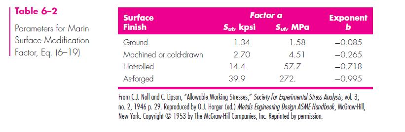
53 Correction factor s for specimen s endurance limit surface factor, C surf (p , Norton s 3 rd ed.) The rotating beam test specimen has a polished surface. Most components do not have a polished surface. Scratches and imperfections on the surface act like a stress raisers and reduce the fatigue life of a part. Use either the graph or the equation with the table shown below. C surf = A (S ut ) b 10/1/
54 Correction factor s for specimen s endurance limit Temperature factor, C temp (p.331, Norton s 3 rd ed.) High temperatures reduce the fatigue life of a component. For accurate results, use an environmental chamber and obtain the endurance limit experimentally at the desired temperature. For operating temperature below 450 o C (840 o F) the temperature factor should be taken as one. C temp = 1 for T 450 o C (840 o F) 10/1/
55 Correction factor s for specimen s endurance limit Reliability factor, C rel (p. 331, Norton s 3 rd ed.) The reliability correction factor accounts for the scatter and uncertainty of material properties (endurance limit). 10/1/
q Notch sensitivity factor (p.")
56 Fatigue Stress Concentration Factor, K f Experimental data shows that the actual stress concentration factor is not as high as indicated by the theoretical value, K t. The stress concentration factor seems to be sensitive to the notch radius and the ultimate strength of the material. Fatigue stress concentration factor K f = 1 + (K t 1)q Notch sensitivity factor (p. 340, Norton s 3 rd ed.) Steel 10/1/


57 Fatigue Stress Concentration Factor, K f for Aluminum (p. 341, Norton s 3 rd ed.) 10/1/
58 Design process Determine the maximum alternating applied stress ( a ) in terms of the size and cross sectional profile Select material S y, S ut Choose a safety factor n Determine all modifying factors and calculate the endurance limit of the component S e Determine the fatigue stress concentration factor, K f Use the design equation to calculate the size S e K f a = n Investigate different cross sections (profiles), optimize for size or weight You may also assume a profile and size, calculate the alternating stress and determine the safety factor. Iterate until you obtain the desired safety factor 10/1/
59 Design for finite life A S S n = a (N) b equation of the fatigue line B S e N Point A S n =.9S ut N = 10 3 Point A S n =.9S ut N = 10 3 Point B S n = S e N = 10 6 Point B S n = S f N = 5x /1/
60 Design for finite life S n = a (N) b log S n = log a + b log N log.9s ut = log a + b log 10 3 Apply boundary conditions for point A and B to find the two constants a and b a = (.9S ut ) 2 S e log S e = log a + b log 10 6 b = 1 3 log.9s ut S e S n = S e ( N ) ⅓ log ( 10 6 S e.9s ut ) Calculate S n and replace S e in the design equation S n K f a = n Design equation 10/1/
61 The effect of mean stress on fatigue life Mean stress exist if the loading is of a repeating or fluctuating type. a Mean stress is not zero Alternating stress S e Gerber curve Goodman line Soderberg line Mean stress S y S ut m 10/1/
62 The effect of mean stress on fatigue life goodman diagram a Yield line Alternating stress Safe zone C Goodman line S y Mean stress S ut m 10/1/
63 The Effect of Mean Stress on Fatigue Life Modified Goodman Diagram a S y Yield line Goodman line Safe zone Safe zone - m - S yc S ut S y + m 10/1/
64 The Effect of Mean Stress on Fatigue Life Modified Goodman Diagram Fatigue, m 0 a Fatigue, m > 0 a m 1 + = S e S ut n f Infinite life Yield a + m = S yc n y a = S e n f Safe zone S e Safe zone a m S ut + = 1 S n C Yield Finite life a + m = S y n y - m - S yc 10/1/
65 Applying Stress Concentration factor to Alternating and Mean Components of Stress Determine the fatigue stress concentration factor, K f, apply directly to the alternating stress K f a If K f max < S y then there is no yielding at the notch, use K fm = K f and multiply the mean stress by K fm K fm m If K f max > S y then there is local yielding at the notch, material at the notch is strain-hardened. The effect of stress concentration is reduced. Calculate the stress concentration factor for the mean stress using the following equation, Fatigue design equation K fm = S y K f a K f a K fm m 1 + = Infinite life S e S ut n f 10/1/ m
66 Combined loading All four components of stress exist, xa xm xya alternating component of normal stress mean component of normal stress alternating component of shear stress xym mean component of shear stress Calculate the alternating and mean principal stresses, 1a, 2a = ( xa /2) ( xa /2) 2 + ( xya ) 2 1m, 2m = ( xm /2) ( xm /2) 2 + ( xym ) 2 10/1/
67 Combined loading Calculate the alternating and mean von Mises stresses, 2 2 a = ( 1a + 2a - 1a 2a) 1/2 2 2 m = ( 1m + 2m - 1m 2m) 1/2 Fatigue design equation a m 1 + = Infinite life S e n f S ut 10/1/

68 Example /1/

69 Example 6-9 Shaft is made from SAE1050 steel and is cold formed 10/1/

70 10/1/

71 Solution 10/1/

72 Solution 10/1/

73 10/1/
CHAPTER 2 Failure/Fracture Criterion
 (11) CHAPTER 2 Failure/Fracture Criterion (12) Failure (Yield) Criteria for Ductile Materials under Plane Stress Designer engineer: 1- Analysis of loading (for simple geometry using what you learn here
MAE 322 Machine Design. Dr. Hodge Jenkins Mercer University
 MAE 322 Machine Design Dr. Hodge Jenkins Mercer University What is this Machine Design course really about? What you will learn: How to design machine elements 1) Design so they won t break under varying
DESIGN FOR FATIGUE STRENGTH
 UNIT 3 DESIGN FOR FATIGUE STRENGTH Instructional Objectives Mean and variable stresses and endurance limit. S-N plots for metals and non-metals and relation between endurance limit and ultimate tensile
Static Failure (pg 206)
") Static Failure (pg 06) All material followed Hookeʹs law which states that strain is proportional to stress applied, until it exceed the proportional limits. It will reach and exceed the elastic limit
Static Failure (pg 06) All material followed Hookeʹs law which states that strain is proportional to stress applied, until it exceed the proportional limits. It will reach and exceed the elastic limit
MAE 322 Machine Design Lecture 2. Dr. Hodge Jenkins Mercer University
 MAE 322 Machine Design Lecture 2 Dr. Hodge Jenkins Mercer University Statics Load Failure Theories to Understand Maximum Normal Stress (MNS) Maximum Shear Stress (MSS) Distortion Energy (DE) Coulomb-Mohr
Failure from static loading
 Failure from static loading Topics Quiz /1/07 Failures from static loading Reading Chapter 5 Homework HW 3 due /1 HW 4 due /8 What is Failure? Failure any change in a machine part which makes it unable
Path to static failure of machine components
 Pat to static failure of macine components Load Stress Discussed last week (w) Ductile material Yield Strain Brittle material Fracture Fracture Dr. P. Buyung Kosasi,Spring 008 Name some of ductile and
Introduction to Engineering Materials ENGR2000. Dr. Coates
 Introduction to Engineering Materials ENGR2 Chapter 6: Mechanical Properties of Metals Dr. Coates 6.2 Concepts of Stress and Strain tension compression shear torsion Tension Tests The specimen is deformed
Pressure Vessels Stresses Under Combined Loads Yield Criteria for Ductile Materials and Fracture Criteria for Brittle Materials
 Pressure Vessels Stresses Under Combined Loads Yield Criteria for Ductile Materials and Fracture Criteria for Brittle Materials Pressure Vessels: In the previous lectures we have discussed elements subjected
MEMS Project 2 Assignment. Design of a Shaft to Transmit Torque Between Two Pulleys
 MEMS 029 Project 2 Assignment Design of a Shaft to Transmit Torque Between Two Pulleys Date: February 5, 206 Instructor: Dr. Stephen Ludwick Product Definition Shafts are incredibly important in order
5. STRESS CONCENTRATIONS. and strains in shafts apply only to solid and hollow circular shafts while they are in the
 5. STRESS CONCENTRATIONS So far in this thesis, most of the formulas we have seen to calculate the stresses and strains in shafts apply only to solid and hollow circular shafts while they are in the elastic
2.1 Background of Piping Stresses
 2 Research Review One of the major additions to Tmin was the inclusion of analysis of a 2-Dimensional vertical piping span. The original plan from Dupont was to include several types of 2-D and 3-D vertical
Lecture #7: Basic Notions of Fracture Mechanics Ductile Fracture
 Lecture #7: Basic Notions of Fracture Mechanics Ductile Fracture by Dirk Mohr ETH Zurich, Department of Mechanical and Process Engineering, Chair of Computational Modeling of Materials in Manufacturing
SOLUTION (17.3) Known: A simply supported steel shaft is connected to an electric motor with a flexible coupling.
 Known: A simply supported steel shaft is connected to an electric motor with a flexible coupling.") SOLUTION (17.3) Known: A simply supported steel shaft is connected to an electric motor with a flexible coupling. Find: Determine the value of the critical speed of rotation for the shaft. Schematic and
SOLUTION (17.3) Known: A simply supported steel shaft is connected to an electric motor with a flexible coupling. Find: Determine the value of the critical speed of rotation for the shaft. Schematic and
Failure surface according to maximum principal stress theory
 Maximum Principal Stress Theory (W. Rankin s Theory- 1850) Brittle Material The maximum principal stress criterion: Rankin stated max principal stress theory as follows- a material fails by fracturing
Module 5: Theories of Failure
 Module 5: Theories of Failure Objectives: The objectives/outcomes of this lecture on Theories of Failure is to enable students for 1. Recognize loading on Structural Members/Machine elements and allowable
Chapter 8 Structural Design and Analysis. Strength and stiffness 5 types of load: Tension Compression Shear Bending Torsion
 Chapter 8 Structural Design and Analysis 1 Strength and stiffness 5 types of load: Tension Compression Shear Bending Torsion Normal Stress Stress is a state when a material is loaded. For normal forces
Stress Analysis Lecture 3 ME 276 Spring Dr./ Ahmed Mohamed Nagib Elmekawy
 Stress Analysis Lecture 3 ME 276 Spring 2017-2018 Dr./ Ahmed Mohamed Nagib Elmekawy Axial Stress 2 Beam under the action of two tensile forces 3 Beam under the action of two tensile forces 4 Shear Stress
5. Repeated Loading. 330:148 (g) Machine Design. Dynamic Strength. Dynamic Loads. Dynamic Strength. Dynamic Strength. Nageswara Rao Posinasetti
 Machine Design. Dynamic Strength. Dynamic Loads. Dynamic Strength. Dynamic Strength. Nageswara Rao Posinasetti") 330:48 (g) achine Design Nageswara Rao Posinasetti P N Rao 5. Repeated Loading Objectives Identify the various kinds of loading encountered on a part and learn to combine them as appropriate. Determine
330:48 (g) achine Design Nageswara Rao Posinasetti P N Rao 5. Repeated Loading Objectives Identify the various kinds of loading encountered on a part and learn to combine them as appropriate. Determine
Mechanical Properties of Materials
 Mechanical Properties of Materials Strains Material Model Stresses Learning objectives Understand the qualitative and quantitative description of mechanical properties of materials. Learn the logic of
Use Hooke s Law (as it applies in the uniaxial direction),
,") 0.6 STRSS-STRAIN RLATIONSHIP Use the principle of superposition Use Poisson s ratio, v lateral longitudinal Use Hooke s Law (as it applies in the uniaxial direction), x x v y z, y y vx z, z z vx y Copyright
0.6 STRSS-STRAIN RLATIONSHIP Use the principle of superposition Use Poisson s ratio, v lateral longitudinal Use Hooke s Law (as it applies in the uniaxial direction), x x v y z, y y vx z, z z vx y Copyright
Sample Questions for the ME328 Machine Design Final Examination Closed notes, closed book, no calculator.
 Sample Questions for the ME328 Machine Design Final Examination Closed notes, closed book, no calculator. The following is from the first page of the examination. I recommend you read it before the exam.
Mechanical Design. Design of Shaft
 Mechanical Design Design of Shaft Outline Practical information Shaft design Definition of shaft? It is a rotating member, in general, has a circular cross-section and is used to transmit power. The shaft
Donald P. Shiley School of Engineering ME 328 Machine Design, Spring 2019 Assignment 1 Review Questions
 Donald P. Shiley School of Engineering ME 328 Machine Design, Spring 2019 Assignment 1 Review Questions Name: This is assignment is in workbook format, meaning you may fill in the blanks (you do not need
MECHANICS OF MATERIALS
 CHATR Stress MCHANICS OF MATRIALS and Strain Axial Loading Stress & Strain: Axial Loading Suitability of a structure or machine may depend on the deformations in the structure as well as the stresses induced
Endurance Strength Pg 274
 [Pg / 8] Fatigue Analysis Pg 257 The Units used as standard: in, kip, kpsi, sec, hp in, kip, kpsi, sec/min, hp Endurance Strength Pg 274 Fatigue failure occurs when a machine element is sujected to fluctuating
ME Final Exam. PROBLEM NO. 4 Part A (2 points max.) M (x) y. z (neutral axis) beam cross-sec+on. 20 kip ft. 0.2 ft. 10 ft. 0.1 ft.
 M (x) y. z (neutral axis) beam cross-sec+on. 20 kip ft. 0.2 ft. 10 ft. 0.1 ft.") ME 323 - Final Exam Name December 15, 2015 Instructor (circle) PROEM NO. 4 Part A (2 points max.) Krousgrill 11:30AM-12:20PM Ghosh 2:30-3:20PM Gonzalez 12:30-1:20PM Zhao 4:30-5:20PM M (x) y 20 kip ft 0.2
ME 323 - Final Exam Name December 15, 2015 Instructor (circle) PROEM NO. 4 Part A (2 points max.) Krousgrill 11:30AM-12:20PM Ghosh 2:30-3:20PM Gonzalez 12:30-1:20PM Zhao 4:30-5:20PM M (x) y 20 kip ft 0.2
MECE 3321 MECHANICS OF SOLIDS CHAPTER 3
 MECE 3321 MECHANICS OF SOLIDS CHAPTER 3 Samantha Ramirez TENSION AND COMPRESSION TESTS Tension and compression tests are used primarily to determine the relationship between σ avg and ε avg in any material.
NORMAL STRESS. The simplest form of stress is normal stress/direct stress, which is the stress perpendicular to the surface on which it acts.
 NORMAL STRESS The simplest form of stress is normal stress/direct stress, which is the stress perpendicular to the surface on which it acts. σ = force/area = P/A where σ = the normal stress P = the centric
Stress concentrations, fracture and fatigue
 Stress concentrations, fracture and fatigue Piet Schreurs Department of Mechanical Engineering Eindhoven University of Technology http://www.mate.tue.nl/ piet December 1, 2016 Overview Stress concentrations
ME311 Machine Design
 ME311 Machine Design Lecture : Materials; Stress & Strain; Power Transmission W Dornfeld 13Sep018 airfield University School of Engineering Stress-Strain Curve for Ductile Material Ultimate Tensile racture
Volume 2 Fatigue Theory Reference Manual
 Volume Fatigue Theory Reference Manual Contents 1 Introduction to fatigue 1.1 Introduction... 1-1 1. Description of the applied loading... 1-1.3 Endurance curves... 1-3 1.4 Generalising fatigue data...
INTRODUCTION (Cont..)
") INTRODUCTION Name : Mohamad Redhwan Abd Aziz Post : Lecturer @ DEAN CENTER OF HND STUDIES Subject : Solid Mechanics Code : BME 2033 Room : CENTER OF HND STUDIES OFFICE H/P No. : 019-2579663 W/SITE : Http://tatiuc.edu.my/redhwan
INTRODUCTION Name : Mohamad Redhwan Abd Aziz Post : Lecturer @ DEAN CENTER OF HND STUDIES Subject : Solid Mechanics Code : BME 2033 Room : CENTER OF HND STUDIES OFFICE H/P No. : 019-2579663 W/SITE : Http://tatiuc.edu.my/redhwan
Outline. Tensile-Test Specimen and Machine. Stress-Strain Curve. Review of Mechanical Properties. Mechanical Behaviour
 Tensile-Test Specimen and Machine Review of Mechanical Properties Outline Tensile test True stress - true strain (flow curve) mechanical properties: - Resilience - Ductility - Toughness - Hardness A standard
ENT345 Mechanical Components Design
 1) LOAD AND STRESS ANALYSIS i. Principle stress ii. The maximum shear stress iii. The endurance strength of shaft. 1) Problem 3-71 A countershaft carrying two-v belt pulleys is shown in the figure. Pulley
ME 202 STRENGTH OF MATERIALS SPRING 2014 HOMEWORK 4 SOLUTIONS
 ÇANKAYA UNIVERSITY MECHANICAL ENGINEERING DEPARTMENT ME 202 STRENGTH OF MATERIALS SPRING 2014 Due Date: 1 ST Lecture Hour of Week 12 (02 May 2014) Quiz Date: 3 rd Lecture Hour of Week 12 (08 May 2014)
MMJ1133 FATIGUE AND FRACTURE MECHANICS A - INTRODUCTION INTRODUCTION
 A - INTRODUCTION INTRODUCTION M.N.Tamin, CSMLab, UTM Course Content: A - INTRODUCTION Mechanical failure modes; Review of load and stress analysis equilibrium equations, complex stresses, stress transformation,
[5] Stress and Strain
![[5] Stress and Strain](/thumbs/95/123344550.jpg "[5] Stress and Strain") [5] Stress and Strain Page 1 of 34 [5] Stress and Strain [5.1] Internal Stress of Solids [5.2] Design of Simple Connections (will not be covered in class) [5.3] Deformation and Strain [5.4] Hooke s Law
[5] Stress and Strain Page 1 of 34 [5] Stress and Strain [5.1] Internal Stress of Solids [5.2] Design of Simple Connections (will not be covered in class) [5.3] Deformation and Strain [5.4] Hooke s Law
University of Pretoria Department of Mechanical & Aeronautical Engineering MOW 227, 2 nd Semester 2014
 Universit of Pretoria Department of Mechanical & Aeronautical Engineering MOW 7, nd Semester 04 Semester Test Date: August, 04 Total: 00 Internal eaminer: Duration: hours Mr. Riaan Meeser Instructions:
MECHANICS OF MATERIALS
 Third E CHAPTER 2 Stress MECHANICS OF MATERIALS Ferdinand P. Beer E. Russell Johnston, Jr. John T. DeWolf Lecture Notes: J. Walt Oler Texas Tech University and Strain Axial Loading Contents Stress & Strain:
Tuesday, February 11, Chapter 3. Load and Stress Analysis. Dr. Mohammad Suliman Abuhaiba, PE
 1 Chapter 3 Load and Stress Analysis 2 Chapter Outline Equilibrium & Free-Body Diagrams Shear Force and Bending Moments in Beams Singularity Functions Stress Cartesian Stress Components Mohr s Circle for
EMA 3702 Mechanics & Materials Science (Mechanics of Materials) Chapter 3 Torsion
 Chapter 3 Torsion") EMA 3702 Mechanics & Materials Science (Mechanics of Materials) Chapter 3 Torsion Introduction Stress and strain in components subjected to torque T Circular Cross-section shape Material Shaft design Non-circular
EMA 3702 Mechanics & Materials Science (Mechanics of Materials) Chapter 3 Torsion Introduction Stress and strain in components subjected to torque T Circular Cross-section shape Material Shaft design Non-circular
Fundamentals of Durability. Unrestricted Siemens AG 2013 All rights reserved. Siemens PLM Software
 Fundamentals of Durability Page 1 Your single provider of solutions System simulation solutions 3D simulation solutions Test-based engineering solutions Engineering services - Deployment services Troubleshooting
ME111 Instructor: Peter Pinsky Class #21 November 13, 2000
 Toda s Topics ME Instructor: Peter Pinsk Class # November,. Consider two designs of a lug wrench for an automobile: (a) single ended, (b) double ended. The distance between points A and B is in. and the
High Tech High Top Hat Technicians. An Introduction to Solid Mechanics. Is that supposed to bend there?
 High Tech High Top Hat Technicians An Introduction to Solid Mechanics Or Is that supposed to bend there? Why don't we fall through the floor? The power of any Spring is in the same proportion with the
Predicting Fatigue Life with ANSYS Workbench
 Predicting Fatigue Life with ANSYS Workbench How To Design Products That Meet Their Intended Design Life Requirements Raymond L. Browell, P. E. Product Manager New Technologies ANSYS, Inc. Al Hancq Development
Structural Analysis I Chapter 4 - Torsion TORSION
 ORSION orsional stress results from the action of torsional or twisting moments acting about the longitudinal axis of a shaft. he effect of the application of a torsional moment, combined with appropriate
Plasticity R. Chandramouli Associate Dean-Research SASTRA University, Thanjavur
 Plasticity R. Chandramouli Associate Dean-Research SASTRA University, Thanjavur-613 401 Joint Initiative of IITs and IISc Funded by MHRD Page 1 of 9 Table of Contents 1. Plasticity:... 3 1.1 Plastic Deformation,
SECOND ENGINEER REG. III/2 APPLIED MECHANICS
 SECOND ENGINEER REG. III/2 APPLIED MECHANICS LIST OF TOPICS Static s Friction Kinematics Dynamics Machines Strength of Materials Hydrostatics Hydrodynamics A STATICS 1 Solves problems involving forces
Engineering Science OUTCOME 1 - TUTORIAL 4 COLUMNS
 Unit 2: Unit code: QCF Level: Credit value: 15 Engineering Science L/601/10 OUTCOME 1 - TUTORIAL COLUMNS 1. Be able to determine the behavioural characteristics of elements of static engineering systems
Module 5: Failure Criteria of Rock and Rock masses. Contents Hydrostatic compression Deviatoric compression
 FAILURE CRITERIA OF ROCK AND ROCK MASSES Contents 5.1 Failure in rocks 5.1.1 Hydrostatic compression 5.1.2 Deviatoric compression 5.1.3 Effect of confining pressure 5.2 Failure modes in rocks 5.3 Complete
MECHANICS OF MATERIALS
 Third CHTR Stress MCHNICS OF MTRIS Ferdinand. Beer. Russell Johnston, Jr. John T. DeWolf ecture Notes: J. Walt Oler Texas Tech University and Strain xial oading Contents Stress & Strain: xial oading Normal
five Mechanics of Materials 1 ARCHITECTURAL STRUCTURES: FORM, BEHAVIOR, AND DESIGN DR. ANNE NICHOLS SUMMER 2017 lecture
 ARCHITECTURAL STRUCTURES: FORM, BEHAVIOR, AND DESIGN DR. ANNE NICHOLS SUMMER 2017 lecture five mechanics www.carttalk.com of materials Mechanics of Materials 1 Mechanics of Materials MECHANICS MATERIALS
D : SOLID MECHANICS. Q. 1 Q. 9 carry one mark each. Q.1 Find the force (in kn) in the member BH of the truss shown.
 in the member BH of the truss shown.") D : SOLID MECHANICS Q. 1 Q. 9 carry one mark each. Q.1 Find the force (in kn) in the member BH of the truss shown. Q.2 Consider the forces of magnitude F acting on the sides of the regular hexagon having
D : SOLID MECHANICS Q. 1 Q. 9 carry one mark each. Q.1 Find the force (in kn) in the member BH of the truss shown. Q.2 Consider the forces of magnitude F acting on the sides of the regular hexagon having
MECHANICS OF MATERIALS
 2009 The McGraw-Hill Companies, Inc. All rights reserved. Fifth SI Edition CHAPTER 3 MECHANICS OF MATERIALS Ferdinand P. Beer E. Russell Johnston, Jr. John T. DeWolf David F. Mazurek Torsion Lecture Notes:
QUESTION BANK SEMESTER: III SUBJECT NAME: MECHANICS OF SOLIDS
 QUESTION BANK SEMESTER: III SUBJECT NAME: MECHANICS OF SOLIDS UNIT 1- STRESS AND STRAIN PART A (2 Marks) 1. Define longitudinal strain and lateral strain. 2. State Hooke s law. 3. Define modular ratio,
ME 243. Mechanics of Solids
 ME 243 Mechanics of Solids Lecture 2: Stress and Strain Ahmad Shahedi Shakil Lecturer, Dept. of Mechanical Engg, BUET E-mail: sshakil@me.buet.ac.bd, shakil6791@gmail.com Website: teacher.buet.ac.bd/sshakil
NAME: Given Formulae: Law of Cosines: Law of Sines:
 NME: Given Formulae: Law of Cosines: EXM 3 PST PROBLEMS (LESSONS 21 TO 28) 100 points Thursday, November 16, 2017, 7pm to 9:30, Room 200 You are allowed to use a calculator and drawing equipment, only.
: APPLIED MECHANICS & STRENGTH OF MATERIALS COURSE CODE : 4021 COURSE CATEGORY : A PERIODS/ WEEK : 5 PERIODS/ SEMESTER : 75 CREDIT : 5 TIME SCHEDULE
 COURSE TITLE : APPLIED MECHANICS & STRENGTH OF MATERIALS COURSE CODE : 4021 COURSE CATEGORY : A PERIODS/ WEEK : 5 PERIODS/ SEMESTER : 75 CREDIT : 5 TIME SCHEDULE MODULE TOPIC PERIODS 1 Simple stresses
COMPLEX STRESS TUTORIAL 4 THEORIES OF FAILURE. You should judge your progress by completing the self assessment exercises.
 COMPLEX STRESS TUTORIAL 4 THEORIES OF FAILURE This short tutorial covers no known elements of the E.C. or Edexcel Exams but should be studied as part of complex stress, structures and materials. You should
Lecture #8: Ductile Fracture (Theory & Experiments)
") Lecture #8: Ductile Fracture (Theory & Experiments) by Dirk Mohr ETH Zurich, Department of Mechanical and Process Engineering, Chair of Computational Modeling of Materials in Manufacturing 2015 1 1 1 Ductile
Lecture #8: Ductile Fracture (Theory & Experiments) by Dirk Mohr ETH Zurich, Department of Mechanical and Process Engineering, Chair of Computational Modeling of Materials in Manufacturing 2015 1 1 1 Ductile
Physical Science and Engineering. Course Information. Course Number: ME 100
 Physical Science and Engineering Course Number: ME 100 Course Title: Course Information Basic Principles of Mechanics Academic Semester: Fall Academic Year: 2016-2017 Semester Start Date: 8/21/2016 Semester
Fatigue and Fracture
 Fatigue and Fracture Multiaxial Fatigue Professor Darrell F. Socie Mechanical Science and Engineering University of Illinois 2004-2013 Darrell Socie, All Rights Reserved When is Multiaxial Fatigue Important?
DEPARTMENT OF CIVIL ENGINEERING
 KINGS COLLEGE OF ENGINEERING DEPARTMENT OF CIVIL ENGINEERING SUBJECT: CE 2252 STRENGTH OF MATERIALS UNIT: I ENERGY METHODS 1. Define: Strain Energy When an elastic body is under the action of external
COURSE TITLE : APPLIED MECHANICS & STRENGTH OF MATERIALS COURSE CODE : 4017 COURSE CATEGORY : A PERIODS/WEEK : 6 PERIODS/ SEMESTER : 108 CREDITS : 5
 COURSE TITLE : APPLIED MECHANICS & STRENGTH OF MATERIALS COURSE CODE : 4017 COURSE CATEGORY : A PERIODS/WEEK : 6 PERIODS/ SEMESTER : 108 CREDITS : 5 TIME SCHEDULE MODULE TOPICS PERIODS 1 Simple stresses
Fatigue calculations in ANSYS Workbench. Martin Eerme
 Fatigue calculations in ANSYS Workbench Martin Eerme What is fatigue? In materials science, fatigue is the progressive and localized structural damage that occurs when a material is subjected to cyclic
ME 2570 MECHANICS OF MATERIALS
 ME 2570 MECHANICS OF MATERIALS Chapter III. Mechanical Properties of Materials 1 Tension and Compression Test The strength of a material depends on its ability to sustain a load without undue deformation
Mechanics of Materials II. Chapter III. A review of the fundamental formulation of stress, strain, and deflection
 Mechanics of Materials II Chapter III A review of the fundamental formulation of stress, strain, and deflection Outline Introduction Assumtions and limitations Axial loading Torsion of circular shafts
Downloaded from Downloaded from / 1
 PURWANCHAL UNIVERSITY III SEMESTER FINAL EXAMINATION-2002 LEVEL : B. E. (Civil) SUBJECT: BEG256CI, Strength of Material Full Marks: 80 TIME: 03:00 hrs Pass marks: 32 Candidates are required to give their
There are three main types of structure - mass, framed and shells.
 STRUCTURES There are three main types of structure - mass, framed and shells. Mass structures perform due to their own weight. An example would be a dam. Frame structures resist loads due to the arrangement
Structural Metals Lab 1.2. Torsion Testing of Structural Metals. Standards ASTM E143: Shear Modulus at Room Temperature
 Torsion Testing of Structural Metals Standards ASTM E143: Shear Modulus at Room Temperature Purpose To determine the shear modulus of structural metals Equipment Tinius-Olsen Lo-Torq Torsion Machine (figure
Multiaxial Fatigue. Professor Darrell F. Socie. Department of Mechanical Science and Engineering University of Illinois at Urbana-Champaign
 Multiaxial Fatigue Professor Darrell F. Socie Department of Mechanical Science and Engineering University of Illinois at Urbana-Champaign 2001-2011 Darrell Socie, All Rights Reserved Contact Information
DESIGN OF SHAFT UNDER FATIGUE LOADING
 DESIGN OF SHAFT UNDER FATIGUE LOADING Aditya Anand, Ashish Aggarwal, Jatin Kumar Mechanical Engineering, Dronacharya College of Engineering, Khentawas, Gurgaon, INDIA Abstract - In this paper, shaft employed
This guide is made for non-experienced FEA users. It provides basic knowledge needed to start your fatigue calculations quickly.
 Quick Fatigue Analysis Guide This guide is made for non-experienced FEA users. It provides basic knowledge needed to start your fatigue calculations quickly. Experienced FEA analysts can also use this
Solid Mechanics Chapter 1: Tension, Compression and Shear
 Solid Mechanics Chapter 1: Tension, Compression and Shear Dr. Imran Latif Department of Civil and Environmental Engineering College of Engineering University of Nizwa (UoN) 1 Why do we study Mechanics
Chapter 3. Load and Stress Analysis
 Chapter 3 Load and Stress Analysis 2 Shear Force and Bending Moments in Beams Internal shear force V & bending moment M must ensure equilibrium Fig. 3 2 Sign Conventions for Bending and Shear Fig. 3 3
Fatigue Algorithm Input
 Methods Fatigue Algorithm Input By default, fe-safe analyses stress datasets that contain elastic stresses The calculation of elastic-plastic stress-strains, where necessary, is performed in fe-safe using
Chapter 6: Plastic Theory
 OHP Mechanical Properties of Materials Chapter 6: Plastic Theory Prof. Wenjea J. Tseng 曾文甲 Department of Materials Engineering National Chung Hsing University wenjea@dragon.nchu.edu.tw Reference: W. F.
Load Determination. Fatigue Life Predictions Infinite Life, Stress Life, Strain Life
 Durability Agenda Durability Basics Fatigue, Stress, Strain Load Determination Measurements, Multi-Body Simulation Loads and Damage S-N Curve, Cycle Counting Load Characterization Establishing Durability
Strength of Materials (15CV 32)
") Strength of Materials (15CV 32) Module 1 : Simple Stresses and Strains Dr. H. Ananthan, Professor, VVIET,MYSURU 8/21/2017 Introduction, Definition and concept and of stress and strain. Hooke s law, Stress-Strain
Strength of Materials (15CV 32) Module 1 : Simple Stresses and Strains Dr. H. Ananthan, Professor, VVIET,MYSURU 8/21/2017 Introduction, Definition and concept and of stress and strain. Hooke s law, Stress-Strain
D : SOLID MECHANICS. Q. 1 Q. 9 carry one mark each.
 GTE 2016 Q. 1 Q. 9 carry one mark each. D : SOLID MECHNICS Q.1 single degree of freedom vibrating system has mass of 5 kg, stiffness of 500 N/m and damping coefficient of 100 N-s/m. To make the system
PES Institute of Technology
 PES Institute of Technology Bangalore south campus, Bangalore-5460100 Department of Mechanical Engineering Faculty name : Madhu M Date: 29/06/2012 SEM : 3 rd A SEC Subject : MECHANICS OF MATERIALS Subject
QUESTION BANK DEPARTMENT: CIVIL SEMESTER: III SUBJECT CODE: CE2201 SUBJECT NAME: MECHANICS OF SOLIDS UNIT 1- STRESS AND STRAIN PART A
 DEPARTMENT: CIVIL SUBJECT CODE: CE2201 QUESTION BANK SEMESTER: III SUBJECT NAME: MECHANICS OF SOLIDS UNIT 1- STRESS AND STRAIN PART A (2 Marks) 1. Define longitudinal strain and lateral strain. 2. State
Spherical Pressure Vessels
 Spherical Pressure Vessels Pressure vessels are closed structures containing liquids or gases under essure. Examples include tanks, pipes, essurized cabins, etc. Shell structures : When essure vessels
Design against fluctuating load
 Design against fluctuating load In many applications, the force acting on the spring is not constants but varies in magnitude with time. The valve springs of automotive engine subjected to millions of
Mechanics of Materials Primer
 Mechanics of Materials rimer Notation: A = area (net = with holes, bearing = in contact, etc...) b = total width of material at a horizontal section d = diameter of a hole D = symbol for diameter E = modulus
Rotating Bending with Constant Torsion and Rotated Bending with Constant or Variable Torsion
 Rotating Bending with Constant Torsion and Rotated Bending with Constant or Variable Torsion B. I. Stoychev 1, S. H. Stefanov 2 1 Department of Engineering Mechanics, Technical University of Gabrovo, 4
EMA 3702 Mechanics & Materials Science (Mechanics of Materials) Chapter 2 Stress & Strain - Axial Loading
 Chapter 2 Stress & Strain - Axial Loading") MA 3702 Mechanics & Materials Science (Mechanics of Materials) Chapter 2 Stress & Strain - Axial Loading MA 3702 Mechanics & Materials Science Zhe Cheng (2018) 2 Stress & Strain - Axial Loading Statics
MA 3702 Mechanics & Materials Science (Mechanics of Materials) Chapter 2 Stress & Strain - Axial Loading MA 3702 Mechanics & Materials Science Zhe Cheng (2018) 2 Stress & Strain - Axial Loading Statics
2. Rigid bar ABC supports a weight of W = 50 kn. Bar ABC is pinned at A and supported at B by rod (1). What is the axial force in rod (1)?
. What is the axial force in rod (1)?") IDE 110 S08 Test 1 Name: 1. Determine the internal axial forces in segments (1), (2) and (3). (a) N 1 = kn (b) N 2 = kn (c) N 3 = kn 2. Rigid bar ABC supports a weight of W = 50 kn. Bar ABC is pinned at
IDE 110 S08 Test 1 Name: 1. Determine the internal axial forces in segments (1), (2) and (3). (a) N 1 = kn (b) N 2 = kn (c) N 3 = kn 2. Rigid bar ABC supports a weight of W = 50 kn. Bar ABC is pinned at
Design and analysis of axle under fatigue life loading condition
 Design and analysis of axle under fatigue life loading condition Research Paper Mehul Pravinchandra Mehta 1 Assistant Professor, 1 Vadodara Institute of Engineering, kotambi, Vadodara, Gujarat, India Mechanical
Fatigue Life. The curve may be plotted as semilogarithmic
 Fatigue Life The total number of cycles for which a specimen sustains before failure is called fatigue (cyclic) life, denoted by N. The graph by plotting values of S a and N is called S-N curve or Wöhler
Brittle Deformation. Earth Structure (2 nd Edition), 2004 W.W. Norton & Co, New York Slide show by Ben van der Pluijm
, 2004 W.W. Norton & Co, New York Slide show by Ben van der Pluijm") Lecture 6 Brittle Deformation Earth Structure (2 nd Edition), 2004 W.W. Norton & Co, New York Slide show by Ben van der Pluijm WW Norton, unless noted otherwise Brittle deformation EarthStructure (2 nd
Lecture 6 Brittle Deformation Earth Structure (2 nd Edition), 2004 W.W. Norton & Co, New York Slide show by Ben van der Pluijm WW Norton, unless noted otherwise Brittle deformation EarthStructure (2 nd
* Many components have multiaxial loads, and some of those have multiaxial loading in critical locations
 Why do Multiaxial Fatigue Calculations? * Fatigue analysis is an increasingly important part of the design and development process * Many components have multiaxial loads, and some of those have multiaxial
2.72 Elements of Mechanical Design
 MIT OpenCourseWare http://ocw.mit.edu 2.72 Elements of Mechanical Design Spring 2009 or information about citing these materials or our Terms of Use, visit: http://ocw.mit.edu/terms. 2.72 Elements of Mechanical
Stress Concentration. Professor Darrell F. Socie Darrell Socie, All Rights Reserved
 Stress Concentration Professor Darrell F. Socie 004-014 Darrell Socie, All Rights Reserved Outline 1. Stress Concentration. Notch Rules 3. Fatigue Notch Factor 4. Stress Intensity Factors for Notches 5.
Design Structural Analysis and Fatigue Calculation of Wing Fuselage Lug Attachment of a Transport Aircraft
 Design Structural Analysis and Fatigue Calculation of Wing Fuselage Lug Attachment of a Transport Aircraft Abraham J Pulickal Machine Design Department of Mechanical Engineering Malla Reddy College of
LECTURES NOTES ON MACHINE DESIGN II. Dr. Mihir Kumar Sutar Asst. Professor Mechanical Engineering Department VSSUT Burla
 LECTURES NOTES ON MACHINE DESIGN II By Dr. Mihir Kumar Sutar Asst. Professor Mechanical Engineering Department VSSUT Burla Syllabus Machine Design-II (M) (Data Books are allowed) Module - I 1. Theories
Bone Tissue Mechanics
 Bone Tissue Mechanics João Folgado Paulo R. Fernandes Instituto Superior Técnico, 2016 PART 1 and 2 Introduction The objective of this course is to study basic concepts on hard tissue mechanics. Hard tissue
Samantha Ramirez, MSE. Stress. The intensity of the internal force acting on a specific plane (area) passing through a point. F 2
 passing through a point. F 2") Samantha Ramirez, MSE Stress The intensity of the internal force acting on a specific plane (area) passing through a point. Δ ΔA Δ z Δ 1 2 ΔA Δ x Δ y ΔA is an infinitesimal size area with a uniform force
Samantha Ramirez, MSE Stress The intensity of the internal force acting on a specific plane (area) passing through a point. Δ ΔA Δ z Δ 1 2 ΔA Δ x Δ y ΔA is an infinitesimal size area with a uniform force
Table of Contents. Preface...xvii. Part 1. Level
 Preface...xvii Part 1. Level 1... 1 Chapter 1. The Basics of Linear Elastic Behavior... 3 1.1. Cohesion forces... 4 1.2. The notion of stress... 6 1.2.1. Definition... 6 1.2.2. Graphical representation...