MATERIAL MECHANICS, SE2126 COMPUTER LAB 2 PLASTICITY
|
|
|
- Arron Stone
- 5 years ago
- Views:
Transcription


1 MATERIAL MECHANICS, SE2126 COMPUTER LAB 2 PLASTICITY
2 PART A INTEGRATED CIRCUIT An integrated circuit can be thought of as a very complex maze of electronic components and metallic connectors. These connectors are generally made from copper, aluminium, tungsten or some other good conductor. The base material of an integrated circuit is usually some insulating and electrically passive material, for example silicon. Consider a very simplified 2D model of a conductor wire made of copper, which is partially embedded in a silicon matrix, see Figure 1. The matrix is considered to be semiinfinite. This could for instance represent a small part of the central processing unit (CPU) of the computer you are working on right now. Through the copper wire a current is flowing and since the copper is not a perfect conductor, there will be some resistance. This resistance will in turn give rise to an increase in temperature. Luckily computers are fitted with cooling devices. But what if this cooling device fails? Cu Si Figure 1. Copper conductor in a silicon matrix You will in this part of the lab investigate what would happen if the copper was given an increase in temperature ΔT, as a result of a failure of the internal cooling device. This increase in temperature is generally very fast and since the difference in thermal expansion for copper and silicon is a whole order of magnitude greater for copper, the thermal expansion for silicon will be ignored.

3 What if ΔT is large enough to plastically deform the conductor wire? What if the cooling is turned on again, or if the computer is turned off and cools down, could there be any permanent mechanical damage to the integrated circuit as a result of this? Could there be any residual tensile stresses that could cause a fracture? Start the ANSYS Mechanical ADPL Product Launcher from the start menu in Windows. There are a few settings you will NEED to MAKE SURE are correct, see Figure 3 and the table below. When this is done, click on Run to start ANSYS. Figure 3. ANSYS Product Launcher. Make sure that the settings are correct! Simulation environment: ANSYS Licence: ANSYS Academic Teaching Advanced Working Directory: C:\TEMP\[ any subfolder of your choice ]
4 First you will need to get two files from the course web page. There is an ANSYS database file GeometryAndMeshPartA.db and a text file PartA-Solver.txt that you will need for this part. The database file contains the model geometry, the mesh and also the material definitions. The matrix is modelled as a cubic anisotropic elastic material with stiffness components C 11, C 12 and C 44 according to Table 1 below. C 11 C 12 C ,9 GPa 63,5 GPa 79,5 GPa Table 1. Stiffness components for cubic elastic silicon matrix. From Wikström, A. Modeling of stresses and deformation in thin film and interconnected line structures Doctoral thesis, Department of Solid Mechanics, KTH, The conductor wire is modelled as a bilinear isotropic elastic-plastic material with isotropic hardening and a thermal expansion coefficient α, see Figure 3 and Table 2. σ E 117 GPa ν 0,34 σ Y E T α 22e-6 K -1 E ε σ Y E T 100 MPa 1,12 GPa Figure 3. Schematic figure of a bilinear elastic-plastic material. Table 2. Material properties for the copper wire. When ANSYS starts, choose File > Resume from and load the file geometry file from where you saved it on the hard drive.
5 Look at the mesh, it is not beautiful, but it will do. If you can not see the mesh you can plot it from the menu Plot and then choose Elements, or you can type the command EPLOT in the ANSYS Command Prompt. The mesh contains at least one triangular element, which is really a collapsed square element. This would generally not be so good if you where using linear elements, since it would be very stiff in bending. Now issue the APLOT command, or choose Plot > Areas from the menu, to look at how the model is built. The model has a symmetry line at x = 0. The circular outer boundary is supposed to be far enough away from the copper wire to simulate an infinite boundary, at least to a first approximation. The model is meshed with PLANE183 8-noded quadratic elements with a plane strain formulation, which is to say that the out of plane dimension is also considered to be large and that there are no strains in the z-direction. Now open the text file that you downloaded from the course home page. This file contains the information for ANSYS on how to solve the model and what boundary conditions to apply. You will only need to change the value for the temperature load, DeltaT. You can leave it at 10 degrees for now. This file will execute two solutions after each other. First it will apply the temperature change to the copper wire and solve, and secondly it will remove the temperature and solve again. Your first task is to find the temperature load for which you get initiation of plastic deformation. Choose File > Read Input from and make ANSYS read the solver text file to initiate the solution process. It should solve this problem quite fast since 10 degrees is not enough to initiate plastic deformation and therefore no nonlinear iterations are required. Wait until both load steps have solved. Now open up the General Postproc from the ANSYS Main Menu to the left. From here you can access all the results and view them or list them in basically any way you want. (As long as this happens to be the same way as ANSYS wants ) The results you are viewing now are the results after the second load step. Look at the von Mises equivalent stress by Plot Results > Contour Plot > Nodal Solu, and there
6 choose Nodal Solution > Stress > von Mises Stress. There might be some residual stresses, but look at the maximum value! The units of the model are in millimetres and Newton so the stresses are given in MPa. These stresses are, to a very good approximation, zero. Why is that do you think? Now from the General Postproc choose Read Results > By Pick and pick the first load step and click on Read. Close that dialogue box and go back and plot the von Mises equivalent stress again. What you are viewing now is the stress state after heating, but before cooling down again. You will still have stress concentrations at the boundary but look instead at the stress state in the copper. To accurately inquire the stress state in the copper part only you will need to select only those elements. By issuing ESEL,S,MAT,,2 you will select only those elements associated with material number 2, in this case the copper. From these results you can actually figure out at what temperature change you will expect the copper wire to experience yielding. You do not have to iterate a solution. Can you figure out how? Hint: Is the solution linear or nonlinear below the temperature you are seeking? How does the stresses relate to the temperature in this case? You know the yield stress, how is that related to the von Mises stress in the yield criterion? 0, Call this initiation temperature change, and write it down on the answer sheet at the end. Confirm it by doing a new analysis with that temperature as the loading. To do this you can just start over by clearing the current analysis and then solving again. Remember to change the loading and save the updated text file. File > Resume from and then just reload the geometry and solve using the text file. Evaluate the maximum residual tensile stresses in both the copper wire and the silicon substrate for a number of temperature changes ranging from to 10. Remember that it is only tensile stresses that can cause fracture; hence looking at the von Mises
7 stress will not give you a meaningful result. Also, to get accurate results you will have to select and interrogate the results for each part separately using the ESEL,S,MAT,,# command (where # should be 1 for the silicon and 2 for the copper).
8 PART B HARDENING OF NOTCHED SPECIMEN In this part of the lab you will consider an ordinary uniaxial tensile test specimen made of common steel with a circumferential notch, see Figure 4. The specimen will be loaded with cyclic tension and compression and you will investigate the effects of different hardening laws. Specifically, you will look at the difference between isotropic hardening and kinematic hardening. You will need the two files from the course home page for this part. The ANSYS database file GeometryPartB.db and the text file PartB-Solver.txt. 2r t a Figure 4. Test specimen with notch. L First you will need to Clear & Start New to get rid of the geometry and results from Part A. Then you should open up the geometry file in the same way as you did in part A. There are a few things you will need to set before you solve the model. First, there is no nonlinear material law; only the elastic properties of steel are predefined (i.e. a Young s modulus of 209 GPa and a Poisson s ratio of 0.3). Secondly, you will need to mesh the geometry. The model is an axisymmetric 2D model with PLANE183 elements. It is important that you make sure that the element type you are using can handle the type of problem you wish to model. You can look in the Help section for the element formulation if you are unsure about whether or not an element is appropriate.

9 Now you will add a nonlinear material property to the specimen. Click on Preprocessor > Material Props > Material Models to open up the Define Material Model Behavior dialogue box. You will start by defining the hardening law as a rate independent, isotropic hardening, bilinear Mises plasticity formulation. In reality this means that you will need to define two values, the yield stress σ Y and the tangential modulus E T. The figure below shows you how to find the correct material formulation. Set the yield stress to 250 MPa and the tangential modulus to one tenth of the Young s modulus (no, not a tenth of the yield stress!). This is quite a lot, but it will also mean that you get some nice results to look at. Now you will need to mesh the model. Under Preprocessor > Meshing you will find the MeshTool, click on that to open it up. Check the Smart Size box and set the slider to 1. Make sure you are meshing areas, and that you use a free mesh with quad shapes, and then click on the Mesh button. Select the area of the specimen and click OK. If for some reason the MeshTool hangs you can do the same by issuing the commands SMRTSIZE,1 and then AMESH,ALL. Open up the text file and make sure that the load is 120 MPa and that the number of load cycles is set to 7. This means that the solver will solve for 15 load steps, 7 tension loads
10 and 7 compression loads, alternating between tension and compression, and then one unloading, see Figure 5. σ One load step Time One load cycle Figure 5. Load history of the notched specimen. Now you can solve your model. This is done by reading the text file into ANSYS. The bottom edge is constrained in y displacement and the load is applied on the top edge. Wait until it finishes the last load step until you do anything. It might take a little while. You are now to record the values for the maximum equivalent plastic strain for each load step. This is a measure of the accumulated plastic deformation that has occurred during the load history. Start by looking at the first results set and record the maximum equivalent plastic strain on a separate sheet of paper, excel sheet or something similar. Repeat this for each load steps results set until you have a list of 15 values for the equivalent plastic strain, one for each load step. You will have to hang on to these values until you have solved the problem again, but with a different hardening law. The easiest way of doing this is by using the General Postproc > Results Viewer, where a sliding bar can be used to change between load step results.
11 Now you will do the same analysis all over again but this time with a kinematic hardening law instead. Except for that, everything else should be set in the same way as you did before. Which of these hardening laws would you expect to give the highest accumulated plastic strain at the end, and why? Now you can plot your results in the designated graph area of the answer sheet.

12 PART C SPHERICAL INDENTER ON FLAT SURFACE. The last part of this lab concerns the modelling of a spherical steel ball pushed into a flat steel surface, as seen in Figure 6. To make matters a little less complicated and to avoid the contact problem between the ball and the flat surface, the ball will be simulated by application of a Hertz contact pressure instead. What you will investigate in this part is what the critical force is that will initiate yielding in the steel block, and also plot a graph of the residual stresses after unloading as a function of applied force. F r p 0 2a Figure 6. A sphere being pushed into a flat surface and the resulting Hertz pressure distribution. In this part you will use text files to both generate the geometry and to solve the problem. Download the files PartC-Preprocessor.txt and PartC-Solver.txt from the course web page.
13 In the pre-processor text file the Hertz pressure calculations are implemented and the model geometry changes as a function of the applied force F. The Hertz pressure distribution is a half circle with radius p 0 according to the equations below /, /, 2 1 1, Now use the command File > Read Input from and make ANSYS read the preprocessor file to generate the geometry and mesh. Look at the geometry and mesh. It is emphasized that the meshed part represents the flat surface, that the ball is not included but modelled by a contact pressure instead and the curved boundary is supposed to represent infinity (quite well actually...). The geometry is very similar to the geometry in Part A, but there is a distinct difference. Both are 2D but this one is axisymmetric about x = 0 instead of having the plane strain formulation. Since the geometry is more structured compared to Part A the mesh can more easily be controlled. As in Part B, ANSYS understands that the line x = 0 is a symmetry line and no symmetry condition needs to be applied there. Run the solver script and look at the result set at the end of the first load step when the solution is finished. Do this by using the command General Postproc > Read Results > By Pick, which will bring up a list of all the result sets. This time ANSYS will have solved the problem with more sub steps in each load step, and the command OUTRES, ALL, ALL that is issued in the solver file will have made ANSYS write the results for all sub steps to the solution data base. The result set you are to look at is the results that are written for time = 1,00. Look at the von Mises effective stress. What is the maximum value of this? Can you use this to estimate at what F initiation of plastic behaviour will occur? To do this you will


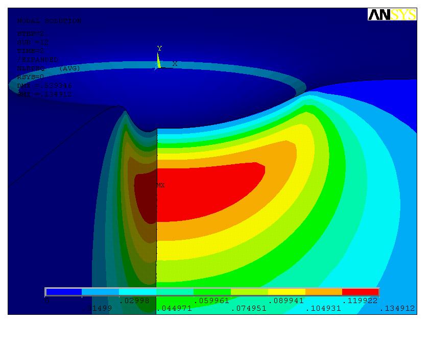
14 need to know that the yield stress is 250 MPa. Call this initiation value F 0 and record it on the answer sheet. Hint: How does yielding relate to the von Mises equivalent stress? What is the relation between the force F, the von Mises equivalent stress and the pressure p 0? What are the values of α and β? Try and solve the model with your value for F 0. Did it give you a small area of residual plastic deformation below the contact point similar to that in Figure 7a below? You can also compare your results to the plot of the first principal residual stress, shown in Figure 7b. Since the model is axisymmetric you can actually bring up a 3D view of the results by doing a symmetry expansion; PlotCtrls > Style > Symmetry Expansion > 2D Axi- Symmetric > ¾ expansion. a) b) Figure 7. a) Residual plastic deformation after loading close to F 0 and then unloading. b) Plot of the first principal stress after unloading. Now you are supposed to solve the model for a few values of F of your own choice and compile a graph of some measure of residual stress as a function of F. What could be a good stress measure to look at, and why? What is it that you might want to know about
15 the stress state after unloading? You are free to choose yourself, but you will have to motivate it. You can also have a look at the remaining deformation. Compared to the other dimensions of the model, this will usually be quite small (unless you give it a real whack, but don t do that). A command that might come in handy then is the Displacement Scaling command accessed via PlotCtrls > Style > Displacement Scaling That s all folks! Until next time, bye!
16 RESULTS FROM PART A INTEGRATED CIRCUIT Threshold temperature for yielding, ΔT 0 : K Maximum residual tensile stress in copper and silicon. (Two curves please!) σ ΔT 0 10ΔT 0 ΔT
17 RESULTS FROM PART B HARDENING OF NOTHCHED SPECIMEN DRAW TWO CURVES, ONE FOR KINEMATIC AND ONE FOR ISOTROPIC HARDENING! ε e pl N steps
18 RESULTS FROM PART C SPHERICAL INDENTER ON FLAT SURFACE Force that will initiate plastic deformation, F 0 : N Residual stress measure, σ res : σ res F F 0
MATERIAL MECHANICS, SE2126 COMPUTER LAB 3 VISCOELASTICITY. k a. N t
 MATERIAL MECHANICS, SE2126 COMPUTER LAB 3 VISCOELASTICITY N t i Gt () G0 1 i ( 1 e τ = α ) i= 1 k a k b τ PART A RELAXING PLASTIC PAPERCLIP Consider an ordinary paperclip made of plastic, as they more
MATERIAL MECHANICS, SE2126 COMPUTER LAB 4 MICRO MECHANICS. E E v E E E E E v E E + + = m f f. f f
 MATRIAL MCHANICS, S226 COMPUTR LAB 4 MICRO MCHANICS 2 2 2 f m f f m T m f m f f m v v + + = + PART A SPHRICAL PARTICL INCLUSION Consider a solid granular material, a so called particle composite, shown
Module 2: Thermal Stresses in a 1D Beam Fixed at Both Ends
 Module 2: Thermal Stresses in a 1D Beam Fixed at Both Ends Table of Contents Problem Description 2 Theory 2 Preprocessor 3 Scalar Parameters 3 Real Constants and Material Properties 4 Geometry 6 Meshing
EXPERIMENT 4: AN ELECTRICAL-THERMAL ACTUATOR
 EXPERIMENT 4: AN ELECTRICAL-THERMAL ACTUATOR 1. OBJECTIVE: 1.1 To analyze an electrical-thermal actuator used in a micro-electromechanical system (MEMS). 2. INTRODUCTION 2.1 Introduction to Thermal Actuator
Module 10: Free Vibration of an Undampened 1D Cantilever Beam
 Module 10: Free Vibration of an Undampened 1D Cantilever Beam Table of Contents Page Number Problem Description Theory Geometry 4 Preprocessor 6 Element Type 6 Real Constants and Material Properties 7
Non-linear and time-dependent material models in Mentat & MARC. Tutorial with Background and Exercises
 Non-linear and time-dependent material models in Mentat & MARC Tutorial with Background and Exercises Eindhoven University of Technology Department of Mechanical Engineering Piet Schreurs July 7, 2009
ANSYS Mechanical Basic Structural Nonlinearities
 Lecture 4 Rate Independent Plasticity ANSYS Mechanical Basic Structural Nonlinearities 1 Chapter Overview The following will be covered in this Chapter: A. Background Elasticity/Plasticity B. Yield Criteria
University of Sheffield The development of finite elements for 3D structural analysis in fire
 The development of finite elements for 3D structural analysis in fire Chaoming Yu, I. W. Burgess, Z. Huang, R. J. Plank Department of Civil and Structural Engineering StiFF 05/09/2006 3D composite structures
Practice Final Examination. Please initial the statement below to show that you have read it
 EN175: Advanced Mechanics of Solids Practice Final Examination School of Engineering Brown University NAME: General Instructions No collaboration of any kind is permitted on this examination. You may use
Stresses Analysis of Petroleum Pipe Finite Element under Internal Pressure
 ISSN : 48-96, Vol. 6, Issue 8, ( Part -4 August 06, pp.3-38 RESEARCH ARTICLE Stresses Analysis of Petroleum Pipe Finite Element under Internal Pressure Dr.Ragbe.M.Abdusslam Eng. Khaled.S.Bagar ABSTRACT
1 332 Laboratories 1. 2 Computational Exercises 1 FEA of a Cantilever Beam... 1 Experimental Laboratory: Tensile Testing of Materials...
 1 332 Laboratories Contents 1 332 Laboratories 1 2 Computational Exercises 1 FEA of a Cantilever Beam.......................................... 1 Experimental Laboratory: Tensile Testing of Materials..........................
Lecture 8. Stress Strain in Multi-dimension
 Lecture 8. Stress Strain in Multi-dimension Module. General Field Equations General Field Equations [] Equilibrium Equations in Elastic bodies xx x y z yx zx f x 0, etc [2] Kinematics xx u x x,etc. [3]
ENGN 2290: Plasticity Computational plasticity in Abaqus
 ENGN 229: Plasticity Computational plasticity in Abaqus The purpose of these exercises is to build a familiarity with using user-material subroutines (UMATs) in Abaqus/Standard. Abaqus/Standard is a finite-element
Stress in Flip-Chip Solder Bumps due to Package Warpage -- Matt Pharr
 Stress in Flip-Chip Bumps due to Package Warpage -- Matt Pharr Introduction As the size of microelectronic devices continues to decrease, interconnects in the devices are scaling down correspondingly.
Mechanical Properties of Materials
 Mechanical Properties of Materials Strains Material Model Stresses Learning objectives Understand the qualitative and quantitative description of mechanical properties of materials. Learn the logic of
Composite FEM Lab-work
 Composite FEM Lab-work You may perform these exercises in groups of max 2 persons. You may also between exercise 5 and 6. Be critical on the results obtained! Exercise 1. Open the file exercise1.inp in
Mechanics of Solids. Mechanics Of Solids. Suraj kr. Ray Department of Civil Engineering
 Mechanics Of Solids Suraj kr. Ray (surajjj2445@gmail.com) Department of Civil Engineering 1 Mechanics of Solids is a branch of applied mechanics that deals with the behaviour of solid bodies subjected
CHAPTER 3 THE EFFECTS OF FORCES ON MATERIALS
 CHAPTER THE EFFECTS OF FORCES ON MATERIALS EXERCISE 1, Page 50 1. A rectangular bar having a cross-sectional area of 80 mm has a tensile force of 0 kn applied to it. Determine the stress in the bar. Stress
6.4 A cylindrical specimen of a titanium alloy having an elastic modulus of 107 GPa ( psi) and
 and") 6.4 A cylindrical specimen of a titanium alloy having an elastic modulus of 107 GPa (15.5 10 6 psi) and an original diameter of 3.8 mm (0.15 in.) will experience only elastic deformation when a tensile
6.4 A cylindrical specimen of a titanium alloy having an elastic modulus of 107 GPa (15.5 10 6 psi) and an original diameter of 3.8 mm (0.15 in.) will experience only elastic deformation when a tensile
Transient Thermal Analysis of a Fin
 Transient Thermal Analysis of a Fin A cylindrical copper fin conducts heat away from its base at 100 0 C and transfers it to a surrounding fluid at 25 0 C through convection. The convection heat transfer
Donald P. Shiley School of Engineering ME 328 Machine Design, Spring 2019 Assignment 1 Review Questions
 Donald P. Shiley School of Engineering ME 328 Machine Design, Spring 2019 Assignment 1 Review Questions Name: This is assignment is in workbook format, meaning you may fill in the blanks (you do not need
Computational Materials Modeling FHLN05 Computer lab
 Motivation Computational Materials Modeling FHLN05 Computer lab In the basic Finite Element (FE) course, the analysis is restricted to materials where the relationship between stress and strain is linear.
A Finite Element Study of Elastic-Plastic Hemispherical Contact Behavior against a Rigid Flat under Varying Modulus of Elasticity and Sphere Radius
 Engineering, 2010, 2, 205-211 doi:10.4236/eng.2010.24030 Published Online April 2010 (http://www. SciRP.org/journal/eng) 205 A Finite Element Study of Elastic-Plastic Hemispherical Contact Behavior against
STANDARD SAMPLE. Reduced section " Diameter. Diameter. 2" Gauge length. Radius
 MATERIAL PROPERTIES TENSILE MEASUREMENT F l l 0 A 0 F STANDARD SAMPLE Reduced section 2 " 1 4 0.505" Diameter 3 4 " Diameter 2" Gauge length 3 8 " Radius TYPICAL APPARATUS Load cell Extensometer Specimen
EMA 3702 Mechanics & Materials Science (Mechanics of Materials) Chapter 2 Stress & Strain - Axial Loading
 Chapter 2 Stress & Strain - Axial Loading") MA 3702 Mechanics & Materials Science (Mechanics of Materials) Chapter 2 Stress & Strain - Axial Loading MA 3702 Mechanics & Materials Science Zhe Cheng (2018) 2 Stress & Strain - Axial Loading Statics
MA 3702 Mechanics & Materials Science (Mechanics of Materials) Chapter 2 Stress & Strain - Axial Loading MA 3702 Mechanics & Materials Science Zhe Cheng (2018) 2 Stress & Strain - Axial Loading Statics
A FINITE ELEMENT STUDY OF ELASTIC-PLASTIC HEMISPHERICAL CONTACT BEHAVIOR AGAINST A RIGID FLAT UNDER VARYING MODULUS OF ELASTICITY AND SPHERE RADIUS
 Proceedings of the International Conference on Mechanical Engineering 2009 (ICME2009) 26-28 December 2009, Dhaka, Bangladesh ICME09- A FINITE ELEMENT STUDY OF ELASTIC-PLASTIC HEMISPHERICAL CONTACT BEHAVIOR
LAB Exercise #4 - Answers The Traction Vector and Stress Tensor. Introduction. Format of lab. Preparation reading
 LAB Exercise #4 - Answers The Traction Vector and Stress Tensor Due: Thursday, 26 February 2009 (Special Thanks to D.D. Pollard who pioneered this exercise in 1991) Introduction Stress concentrations in
INCREASING RUPTURE PREDICTABILITY FOR ALUMINUM
 1 INCREASING RUPTURE PREDICTABILITY FOR ALUMINUM Influence of anisotropy Daniel Riemensperger, Adam Opel AG Paul Du Bois, PDB 2 www.opel.com CONTENT Introduction/motivation Isotropic & anisotropic material
Plane and axisymmetric models in Mentat & MARC. Tutorial with some Background
 Plane and axisymmetric models in Mentat & MARC Tutorial with some Background Eindhoven University of Technology Department of Mechanical Engineering Piet J.G. Schreurs Lambèrt C.A. van Breemen March 6,
TABLE OF CONTENTS CHAPTER TITLE PAGE DECLARATION DEDICATION ACKNOWLEDGEMENT ABSTRACT ABSTRAK
 vii TABLE OF CONTENTS CHAPTER TITLE PAGE DECLARATION DEDICATION ACKNOWLEDGEMENT ABSTRACT ABSTRAK TABLE OF CONTENTS LIST OF TABLES LIST OF FIGURES LIST OF ABBREVIATIONS LIST OF SYMBOLS ii iii iv v vi vii
Prediction of the bilinear stress-strain curve of engineering material by nanoindentation test
 Prediction of the bilinear stress-strain curve of engineering material by nanoindentation test T.S. Yang, T.H. Fang, C.T. Kawn, G.L. Ke, S.Y. Chang Institute of Mechanical & Electro-Mechanical Engineering,
ME Final Exam. PROBLEM NO. 4 Part A (2 points max.) M (x) y. z (neutral axis) beam cross-sec+on. 20 kip ft. 0.2 ft. 10 ft. 0.1 ft.
 M (x) y. z (neutral axis) beam cross-sec+on. 20 kip ft. 0.2 ft. 10 ft. 0.1 ft.") ME 323 - Final Exam Name December 15, 2015 Instructor (circle) PROEM NO. 4 Part A (2 points max.) Krousgrill 11:30AM-12:20PM Ghosh 2:30-3:20PM Gonzalez 12:30-1:20PM Zhao 4:30-5:20PM M (x) y 20 kip ft 0.2
ME 323 - Final Exam Name December 15, 2015 Instructor (circle) PROEM NO. 4 Part A (2 points max.) Krousgrill 11:30AM-12:20PM Ghosh 2:30-3:20PM Gonzalez 12:30-1:20PM Zhao 4:30-5:20PM M (x) y 20 kip ft 0.2
Bending Load & Calibration Module
 Bending Load & Calibration Module Objectives After completing this module, students shall be able to: 1) Conduct laboratory work to validate beam bending stress equations. 2) Develop an understanding of
UNLOADING OF AN ELASTIC-PLASTIC LOADED SPHERICAL CONTACT
 2004 AIMETA International Tribology Conference, September 14-17, 2004, Rome, Italy UNLOADING OF AN ELASTIC-PLASTIC LOADED SPHERICAL CONTACT Yuri KLIGERMAN( ), Yuri Kadin( ), Izhak ETSION( ) Faculty of
EFFECT OF STRAIN HARDENING ON ELASTIC-PLASTIC CONTACT BEHAVIOUR OF A SPHERE AGAINST A RIGID FLAT A FINITE ELEMENT STUDY
 Proceedings of the International Conference on Mechanical Engineering 2009 (ICME2009) 26-28 December 2009, Dhaka, Bangladesh ICME09- EFFECT OF STRAIN HARDENING ON ELASTIC-PLASTIC CONTACT BEHAVIOUR OF A
Predicting Fatigue Life with ANSYS Workbench
 Predicting Fatigue Life with ANSYS Workbench How To Design Products That Meet Their Intended Design Life Requirements Raymond L. Browell, P. E. Product Manager New Technologies ANSYS, Inc. Al Hancq Development
Project. First Saved Monday, June 27, 2011 Last Saved Wednesday, June 29, 2011 Product Version 13.0 Release
 Project First Saved Monday, June 27, 2011 Last Saved Wednesday, June 29, 2011 Product Version 13.0 Release Contents Units Model (A4, B4) o Geometry! Solid Bodies! Parts! Parts! Body Groups! Parts! Parts
NORMAL STRESS. The simplest form of stress is normal stress/direct stress, which is the stress perpendicular to the surface on which it acts.
 NORMAL STRESS The simplest form of stress is normal stress/direct stress, which is the stress perpendicular to the surface on which it acts. σ = force/area = P/A where σ = the normal stress P = the centric
CHAPTER 7 FINITE ELEMENT ANALYSIS OF DEEP GROOVE BALL BEARING
 113 CHAPTER 7 FINITE ELEMENT ANALYSIS OF DEEP GROOVE BALL BEARING 7. 1 INTRODUCTION Finite element computational methodology for rolling contact analysis of the bearing was proposed and it has several
Computational Inelasticity FHLN05. Assignment A non-linear elasto-plastic problem
 Computational Inelasticity FHLN05 Assignment 2018 A non-linear elasto-plastic problem General instructions A written report should be submitted to the Division of Solid Mechanics no later than November
Example-3. Title. Description. Cylindrical Hole in an Infinite Mohr-Coulomb Medium
 Example-3 Title Cylindrical Hole in an Infinite Mohr-Coulomb Medium Description The problem concerns the determination of stresses and displacements for the case of a cylindrical hole in an infinite elasto-plastic
Lecture #7: Basic Notions of Fracture Mechanics Ductile Fracture
 Lecture #7: Basic Notions of Fracture Mechanics Ductile Fracture by Dirk Mohr ETH Zurich, Department of Mechanical and Process Engineering, Chair of Computational Modeling of Materials in Manufacturing
Structural Metals Lab 1.2. Torsion Testing of Structural Metals. Standards ASTM E143: Shear Modulus at Room Temperature
 Torsion Testing of Structural Metals Standards ASTM E143: Shear Modulus at Room Temperature Purpose To determine the shear modulus of structural metals Equipment Tinius-Olsen Lo-Torq Torsion Machine (figure
ULTIMATE STRENGTH OF SQUARE PLATE WITH RECTANGULAR OPENING UNDER AXIAL COMPRESSION
 Journal of Naval Architecture and Marine Engineering June, 2007 http://jname.8m.net ULTIMATE STRENGTH OF SQUARE PLATE WITH RECTANGULAR OPENING UNDER AXIAL COMPRESSION M. Suneel Kumar 1*, P. Alagusundaramoorthy
The University of Melbourne Engineering Mechanics
 The University of Melbourne 436-291 Engineering Mechanics Tutorial Four Poisson s Ratio and Axial Loading Part A (Introductory) 1. (Problem 9-22 from Hibbeler - Statics and Mechanics of Materials) A short
ME 2570 MECHANICS OF MATERIALS
 ME 2570 MECHANICS OF MATERIALS Chapter III. Mechanical Properties of Materials 1 Tension and Compression Test The strength of a material depends on its ability to sustain a load without undue deformation
1 INTRODUCTION 2 SAMPLE PREPARATIONS
 Chikage NORITAKE This study seeks to analyze the reliability of three-dimensional (3D) chip stacked packages under cyclic thermal loading. The critical areas of 3D chip stacked packages are defined using
Outline. Tensile-Test Specimen and Machine. Stress-Strain Curve. Review of Mechanical Properties. Mechanical Behaviour
 Tensile-Test Specimen and Machine Review of Mechanical Properties Outline Tensile test True stress - true strain (flow curve) mechanical properties: - Resilience - Ductility - Toughness - Hardness A standard
BioMechanics and BioMaterials Lab (BME 541) Experiment #5 Mechanical Prosperities of Biomaterials Tensile Test
 Experiment #5 Mechanical Prosperities of Biomaterials Tensile Test") BioMechanics and BioMaterials Lab (BME 541) Experiment #5 Mechanical Prosperities of Biomaterials Tensile Test Objectives 1. To be familiar with the material testing machine(810le4) and provide a practical
BioMechanics and BioMaterials Lab (BME 541) Experiment #5 Mechanical Prosperities of Biomaterials Tensile Test Objectives 1. To be familiar with the material testing machine(810le4) and provide a practical
Lab Exercise #3: Torsion
 Lab Exercise #3: Pre-lab assignment: Yes No Goals: 1. To evaluate the equations of angular displacement, shear stress, and shear strain for a shaft undergoing torsional stress. Principles: testing of round
Effect of Strain Hardening on Unloading of a Deformable Sphere Loaded against a Rigid Flat A Finite Element Study
 Effect of Strain Hardening on Unloading of a Deformable Sphere Loaded against a Rigid Flat A Finite Element Study Biplab Chatterjee, Prasanta Sahoo 1 Department of Mechanical Engineering, Jadavpur University
Exercise: concepts from chapter 8
 Reading: Fundamentals of Structural Geology, Ch 8 1) The following exercises explore elementary concepts associated with a linear elastic material that is isotropic and homogeneous with respect to elastic
Influence of residual stresses in the structural behavior of. tubular columns and arches. Nuno Rocha Cima Gomes
 October 2014 Influence of residual stresses in the structural behavior of Abstract tubular columns and arches Nuno Rocha Cima Gomes Instituto Superior Técnico, Universidade de Lisboa, Portugal Contact:
Mechanical properties 1 Elastic behaviour of materials
 MME131: Lecture 13 Mechanical properties 1 Elastic behaviour of materials A. K. M. B. Rashid Professor, Department of MME BUET, Dhaka Today s Topics Deformation of material under the action of a mechanical
Stress-Strain Behavior
 Stress-Strain Behavior 6.3 A specimen of aluminum having a rectangular cross section 10 mm 1.7 mm (0.4 in. 0.5 in.) is pulled in tension with 35,500 N (8000 lb f ) force, producing only elastic deformation.
ELEC 1908 The Electric Potential (V) March 28, 2013
 March 28, 2013") ELEC 1908 The Electric Potential (V) March 28, 2013 1 Abstract The objective of this lab is to solve numerically Laplace s equation in order to obtain the electric potential distribution in di erent electric
ELEC 1908 The Electric Potential (V) March 28, 2013 1 Abstract The objective of this lab is to solve numerically Laplace s equation in order to obtain the electric potential distribution in di erent electric
Which expression gives the elastic energy stored in the stretched wire?
 1 wire of length L and cross-sectional area is stretched a distance e by a tensile force. The Young modulus of the material of the wire is E. Which expression gives the elastic energy stored in the stretched
6 Examples of pneumatic structures and material models for membranes
 6 Examples of pneumatic structures and material models for membranes This chapter is divided in two main topics: material models for membranes and static analysis of pneumatic structures. Initially uniaxial
Nonlinear Finite Element Modeling of Nano- Indentation Group Members: Shuaifang Zhang, Kangning Su. ME 563: Nonlinear Finite Element Analysis.
 ME 563: Nonlinear Finite Element Analysis Spring 2016 Nonlinear Finite Element Modeling of Nano- Indentation Group Members: Shuaifang Zhang, Kangning Su Department of Mechanical and Nuclear Engineering,
The science of elasticity
 The science of elasticity In 1676 Hooke realized that 1.Every kind of solid changes shape when a mechanical force acts on it. 2.It is this change of shape which enables the solid to supply the reaction
Chapter 7. Highlights:
 Chapter 7 Highlights: 1. Understand the basic concepts of engineering stress and strain, yield strength, tensile strength, Young's(elastic) modulus, ductility, toughness, resilience, true stress and true
Fig. 1. Different locus of failure and crack trajectories observed in mode I testing of adhesively bonded double cantilever beam (DCB) specimens.
 specimens.") a). Cohesive Failure b). Interfacial Failure c). Oscillatory Failure d). Alternating Failure Fig. 1. Different locus of failure and crack trajectories observed in mode I testing of adhesively bonded double
a). Cohesive Failure b). Interfacial Failure c). Oscillatory Failure d). Alternating Failure Fig. 1. Different locus of failure and crack trajectories observed in mode I testing of adhesively bonded double
Elastic Properties of Solid Materials. Notes based on those by James Irvine at
 Elastic Properties of Solid Materials Notes based on those by James Irvine at www.antonine-education.co.uk Key Words Density, Elastic, Plastic, Stress, Strain, Young modulus We study how materials behave
Design of a fastener based on negative Poisson's ratio foam adapted from
 1 Design of a fastener based on negative Poisson's ratio foam adapted from Choi, J. B. and Lakes, R. S., "Design of a fastener based on negative Poisson's ratio foam", Cellular Polymers, 10, 205-212 (1991).
ALGORITHM FOR NON-PROPORTIONAL LOADING IN SEQUENTIALLY LINEAR ANALYSIS
 9th International Conference on Fracture Mechanics of Concrete and Concrete Structures FraMCoS-9 Chenjie Yu, P.C.J. Hoogenboom and J.G. Rots DOI 10.21012/FC9.288 ALGORITHM FOR NON-PROPORTIONAL LOADING
An example solution of a panel in the elastic-plastic regime
 An example solution of a panel in the elastic-plastic regime Piotr Mika May, 2013 1. Example solution of the panel with ABAQUS program The purpose is to analyze an elastic-plastic panel. The elastic solution
MITOCW MITRES2_002S10nonlinear_lec15_300k-mp4
 MITOCW MITRES2_002S10nonlinear_lec15_300k-mp4 The following content is provided under a Creative Commons license. Your support will help MIT OpenCourseWare continue to offer high quality educational resources
3.22 Mechanical Properties of Materials Spring 2008
 MIT OpenCourseWare http://ocw.mit.edu 3.22 Mechanical Properties of Materials Spring 2008 For information about citing these materials or our Terms of Use, visit: http://ocw.mit.edu/terms. Quiz #1 Example
FEA A Guide to Good Practice. What to expect when you re expecting FEA A guide to good practice
 FEA A Guide to Good Practice What to expect when you re expecting FEA A guide to good practice 1. Background Finite Element Analysis (FEA) has transformed design procedures for engineers. Allowing more
Unit 18 Other Issues In Buckling/Structural Instability
 Unit 18 Other Issues In Buckling/Structural Instability Readings: Rivello Timoshenko Jones 14.3, 14.5, 14.6, 14.7 (read these at least, others at your leisure ) Ch. 15, Ch. 16 Theory of Elastic Stability
Solid Mechanics Homework Answers
 Name: Date: Solid Mechanics Homework nswers Please show all of your work, including which equations you are using, and circle your final answer. Be sure to include the units in your answers. 1. The yield
Chapter 6: Mechanical Properties of Metals. Dr. Feras Fraige
 Chapter 6: Mechanical Properties of Metals Dr. Feras Fraige Stress and Strain Tension Compression Shear Torsion Elastic deformation Plastic Deformation Yield Strength Tensile Strength Ductility Toughness
Stress and Displacement Analysis of a Rectangular Plate with Central Elliptical Hole
 Stress and Displacement Analysis of a Rectangular Plate with Central Elliptical Hole Dheeraj Gunwant, J. P. Singh mailto.dheerajgunwant@gmail.com, jitenderpal2007@gmail.com, AIT, Rampur Abstract- A static
Introduction to Engineering Materials ENGR2000. Dr. Coates
 Introduction to Engineering Materials ENGR2 Chapter 6: Mechanical Properties of Metals Dr. Coates 6.2 Concepts of Stress and Strain tension compression shear torsion Tension Tests The specimen is deformed
3-D Finite Element Analysis of Instrumented Indentation of Transversely Isotropic Materials
 3-D Finite Element Analysis of Instrumented Indentation of Transversely Isotropic Materials Abstract: Talapady S. Bhat and T. A. Venkatesh Department of Material Science and Engineering Stony Brook University,
EDEXCEL NATIONAL CERTIFICATE/DIPLOMA MECHANICAL PRINCIPLES AND APPLICATIONS NQF LEVEL 3 OUTCOME 1 - LOADING SYSTEMS TUTORIAL 3 LOADED COMPONENTS
 EDEXCEL NATIONAL CERTIICATE/DIPLOMA MECHANICAL PRINCIPLES AND APPLICATIONS NQ LEVEL 3 OUTCOME 1 - LOADING SYSTEMS TUTORIAL 3 LOADED COMPONENTS 1. Be able to determine the effects of loading in static engineering
Samantha Ramirez, MSE. Stress. The intensity of the internal force acting on a specific plane (area) passing through a point. F 2
 passing through a point. F 2") Samantha Ramirez, MSE Stress The intensity of the internal force acting on a specific plane (area) passing through a point. Δ ΔA Δ z Δ 1 2 ΔA Δ x Δ y ΔA is an infinitesimal size area with a uniform force
Samantha Ramirez, MSE Stress The intensity of the internal force acting on a specific plane (area) passing through a point. Δ ΔA Δ z Δ 1 2 ΔA Δ x Δ y ΔA is an infinitesimal size area with a uniform force
X has a higher value of the Young modulus. Y has a lower maximum tensile stress than X
 Bulk Properties of Solids Old Exam Questions Q1. The diagram shows how the stress varies with strain for metal specimens X and Y which are different. Both specimens were stretched until they broke. Which
Solid Mechanics Chapter 1: Tension, Compression and Shear
 Solid Mechanics Chapter 1: Tension, Compression and Shear Dr. Imran Latif Department of Civil and Environmental Engineering College of Engineering University of Nizwa (UoN) 1 Why do we study Mechanics
Use Hooke s Law (as it applies in the uniaxial direction),
,") 0.6 STRSS-STRAIN RLATIONSHIP Use the principle of superposition Use Poisson s ratio, v lateral longitudinal Use Hooke s Law (as it applies in the uniaxial direction), x x v y z, y y vx z, z z vx y Copyright
0.6 STRSS-STRAIN RLATIONSHIP Use the principle of superposition Use Poisson s ratio, v lateral longitudinal Use Hooke s Law (as it applies in the uniaxial direction), x x v y z, y y vx z, z z vx y Copyright
Burst pressure estimation of reworked nozzle weld on spherical domes
 Indian Journal of Engineering & Materials Science Vol. 21, February 2014, pp. 88-92 Burst pressure estimation of reworked nozzle weld on spherical domes G Jegan Lal a, Jayesh P a & K Thyagarajan b a Cryo
EQUIVALENT FRACTURE ENERGY CONCEPT FOR DYNAMIC RESPONSE ANALYSIS OF PROTOTYPE RC GIRDERS
 EQUIVALENT FRACTURE ENERGY CONCEPT FOR DYNAMIC RESPONSE ANALYSIS OF PROTOTYPE RC GIRDERS Abdul Qadir Bhatti 1, Norimitsu Kishi 2 and Khaliq U Rehman Shad 3 1 Assistant Professor, Dept. of Structural Engineering,
Computational Inelasticity FHLN05. Assignment A non-linear elasto-plastic problem
 Computational Inelasticity FHLN05 Assignment 2017 A non-linear elasto-plastic problem General instructions A written report should be submitted to the Division of Solid Mechanics no later than October
Cable Tension APPENDIX D. Objectives: Demonstrate the use of elastic-plastic material properties. Create an enforced displacement on the model.
 APPENDIX D Cable Tension Objectives: Demonstrate the use of elastic-plastic material properties. Create an enforced displacement on the model. Run an MSC.Nastran nonlinear static analysis. Create an accurate
Impact and Fracture Mechanics Assessment of a Fused Silica Window
 Arnold AFB Wind Tunnel Impact and Fracture Mechanics Analysis Rev-0 1 of 41 Impact and Fracture Mechanics Assessment of a Fused Silica Window Objective: Determine the survival probability of a fused silica
Abstract. 1 Introduction
 Contact analysis for the modelling of anchors in concrete structures H. Walter*, L. Baillet** & M. Brunet* *Laboratoire de Mecanique des Solides **Laboratoire de Mecanique des Contacts-CNRS UMR 5514 Institut
Multilayer contacts in electrical connectors: experimental results and modelling
 Computer Methods and Experimental Measurements VIII 89 Multilayer contacts in electrical connectors: experimental results and modelling F. Ossart 1, S. Noel 1, D. Alamarguy 1, S. Correia 2 & P. Gendre
CHAPTER THREE SYMMETRIC BENDING OF CIRCLE PLATES
 CHAPTER THREE SYMMETRIC BENDING OF CIRCLE PLATES * Governing equations in beam and plate bending ** Solution by superposition 1.1 From Beam Bending to Plate Bending 1.2 Governing Equations For Symmetric
INTERNATIONAL JOURNAL OF CIVIL AND STRUCTURAL ENGINEERING Volume 4, No 1, 2013
 INTERNATIONAL JOURNAL OF CIVIL AND STRUCTURAL ENGINEERING Volume 4, No 1, 2013 Copyright by the authors - Licensee IPA- Under Creative Commons license 3.0 Research article ISSN 0976 4399 Nanoindentation
Experimental and theoretical characterization of Li 2 TiO 3 and Li 4 SiO 4 pebbles
 Experimental and theoretical characterization of Li 2 TiO 3 and Li 4 SiO 4 s D. Aquaro 1 N. Zaccari ABSTRACT Dipartimento di Ingegneria Meccanica Nucleare e della Produzione University of Pisa (Italy)
Geology 2112 Principles and Applications of Geophysical Methods WEEK 1. Lecture Notes Week 1
 Lecture Notes Week 1 A Review of the basic properties and mechanics of materials Suggested Reading: Relevant sections from any basic physics or engineering text. Objectives: Review some basic properties
Modelling the behaviour of plastics for design under impact
 Modelling the behaviour of plastics for design under impact G. Dean and L. Crocker MPP IAG Meeting 6 October 24 Land Rover door trim Loading stages and selected regions Project MPP7.9 Main tasks Tests
Worksheet for Exploration 24.1: Flux and Gauss's Law
 Worksheet for Exploration 24.1: Flux and Gauss's Law In this Exploration, we will calculate the flux, Φ, through three Gaussian surfaces: green, red and blue (position is given in meters and electric field
Using MATLAB and. Abaqus. Finite Element Analysis. Introduction to. Amar Khennane. Taylor & Francis Croup. Taylor & Francis Croup,
 Introduction to Finite Element Analysis Using MATLAB and Abaqus Amar Khennane Taylor & Francis Croup Boca Raton London New York CRC Press is an imprint of the Taylor & Francis Croup, an informa business
Finite element simulation of residual stresses in laser heating
 IAS-2008-66-546ST Finite element simulation of residual stresses in laser heating G. H. Farrahi 1, M. Sistaninia 2, H. Moeinoddini 3 1,2-School of Mechanical Engineering, Sharif University of Technology,
CSCE 155N Fall Homework Assignment 2: Stress-Strain Curve. Assigned: September 11, 2012 Due: October 02, 2012
 CSCE 155N Fall 2012 Homework Assignment 2: Stress-Strain Curve Assigned: September 11, 2012 Due: October 02, 2012 Note: This assignment is to be completed individually - collaboration is strictly prohibited.
STRUCTURAL ANALYSIS OF THE LIFTING DEVICE DETECTOR SUPPORTS FOR THE LHCb VERTEX LOCATOR (VELO)
") National Institute for Nuclear Physics and High Energy Physics Kruislaan 409 1098 SJ Amsterdam The Netherlands NIKHEF Reference no.: MT-VELO 04-2 EDMS no: 466608 OF THE LIFTING DEVICE DETECTOR SUPPORTS
National Institute for Nuclear Physics and High Energy Physics Kruislaan 409 1098 SJ Amsterdam The Netherlands NIKHEF Reference no.: MT-VELO 04-2 EDMS no: 466608 OF THE LIFTING DEVICE DETECTOR SUPPORTS
Transactions on Modelling and Simulation vol 9, 1995 WIT Press, ISSN X
 Elastic-plastic model of crack growth under fatigue using the boundary element method M. Scibetta, O. Pensis LTAS Fracture Mechanics, University ofliege, B-4000 Liege, Belgium Abstract Life of mechanic
AERO 214. Lab II. Measurement of elastic moduli using bending of beams and torsion of bars
 AERO 214 Lab II. Measurement of elastic moduli using bending of beams and torsion of bars BENDING EXPERIMENT Introduction Flexural properties of materials are of interest to engineers in many different
Failure modes of glass panels subjected to soft missile impact
 Failure modes of glass panels subjected to soft missile impact L. R. Dharani & J. Yu Dept. of Mech. and Aerospace Engineering and Engineering Mechanics, University of Missouri-Rolla, U.S.A. Abstract Damage