Les Houches School of Physics Lecture 1: Piezoelectricity & mechanical resonators
|
|
|
- Laurel Bates
- 5 years ago
- Views:
Transcription
1 Les Houches School of Physics Lecture 1: Piezoelectricity & mechanical resonators Institute for Molecular Engineering Andrew Cleland August 2015 Ecole de Physique Les Houches


2 πιέζειν ήλεκτρον Piezoelectricity 1880: Paul-Jacques Curie (age 24) and Pierre Curie (age 21) discover that some materials under stress generate electric voltages. They term this effect piezoelectricity. piezin to squeeze or press electron amber from tree resin (an early source of static electric charge via friction) 1881: Following a theoretical prediction based on symmetry by the mathematician Gabriel Lippman, they discover that conversely electric voltages cause stress. The Curie brothers then build the piezoelectric quartz electrometer, an electromechanical transducer for measuring very small electric currents, later used by Pierre & Marie Curie for studies in radioactivity (NP 1906). Piezoelectric quartz electrometer Little is done for the next 30 years...

.")

3 Langevin Sandwich Transducer Paul Langevin ( ): Student of Pierre Curie s, invents a metal-piezoelectric-metal sandwich now called a Langevin sandwich transducer. Uses this device as a source and receiver of acoustic signals in water, later called sonar (1916). This is the second practical application of piezoelectricity (after electrometer). metal piezoelectric metal Langevin s British patent 145,691 (1918) for sending & receiving sound waves for detecting submarines, icebergs, or other echo-reflecting objects Langevin sandwich transducers, for ultrasonic cleaners. Found on indiamart.com
 worked in parallel with Langevin to develop piezoelectric acoustic sensors.")


4 Sonar Ernest Rutherford and his student Robert William Boyle (not the chemist!) worked in parallel with Langevin to develop piezoelectric acoustic sensors. Ernest Rutherford ( ) Robert William Boyle ( ) Robert Boyle s failed attempt to replicate Rutherford s early experiments with detecting sound using piezoelectric quartz. Boyle then worked with Langevin to develop practical ultrasonic sonar; 1917 the UK developed ASDIC, with prototypes tested during WWI.
5 Langevin sandwich transducer metal piezoelectric metal Displacement ½ wave resonance neutral plane Stress-free top and bottom surface Metal properties differ (somewhat) from piezo properties Operates at ½ wave resonant frequency ( 2 ) Voltage generates stress; stress generates voltage
 Hooke s law relates")


6 Stress / (N/m 2 ) Stress, strain, and all that Strain Δ (dimensionless) Hooke s law relates stress and strain: F Area A length L F Local displacement, : vector displacement of solid from rest point Stress ΔL/2 ΔL/2 stress Young s modulus strain Strain are elastic moduli (N/m 2 )
7 Stress, strain, and all that


8 Stress, strain, and all that Write symmetric strain tensor as a six-component vector: = Six-vector form of Hooke s law: sixvector stress 6 by 6 elastic modulus tensor Isotropic solid has two independent elastic moduli: and 0 0 sixvector strain 2 is the shear modulus
9 Stress, strain, and all that Lamé constants 2 Dynamic equation for an isotropic solid: Differential cube or Young s modulus and the Poisson ratio: 3 2 Net force along : 2 Force original location Newton s law: Newton s law for stress: isotropic solid
10 Mechanical Loss Many different models for mechanical loss/dissipation Specific models for specific type of loss mechanism Some examples: Two-level states Thermoelastic loss Phonon-phonon Phonon-electron Hooke s law for an elastic solid: Zener s empirical model for an anelastic solid: constant strain relaxation time relaxed modulus Microplastic deformation Elastic hysteresis... Harmonic motion: 1 1 constant stress relaxation time
11 Zener s Inelastic Solid Model Harmonic stress & strain: 1 1 Static/equilibrium: (relaxed modulus Hooke s law) High frequency/adiabatic: Intermediate frequencies: Strain & stress out of phase Mechanical loss 1 log 1 (unrelaxed modulus Hooke s law) Complex elastic modulus: 1 Frequency dependent loss (similar to Drude model): 2 1
12 Piezoelectricity Piezoelectricity couples mechanical deformation and electric fields Electric displacement & field: or Stress and strain: or Piezoelectric material: 6 by 3 piezoelectric tensor In component form: 1 3 and 1 6 Combine with Newton s law for stress:
13 Langevin sandwich transducer The Langevin sandwich transducer provides a good workable example (using many approximations): metal piezoelectric insulator metal For simplicity assume: Massless & zero thickness metal (only serves to define voltage) Isotropic mechanical response for piezoelectric: Elastic constant Piezoelectric response along : Piezoelectric constant
14 Langevin sandwich transducer (remainder of this example worked out on blackboard) dilatational resonator.pdf
15 Dilatational Resonator Andrew N Cleland IME - University of Chicago 1
16 Consider first a non-piezoelectric material. For dilatational vibration along the z-axis, the relevant strain component in 6-vector notation is S 3 (this is S 33 or S zz in tensor notation). We will use u(z, t) to represent the z-axis relative displacement, so S 3 = u/ z. We take this as the only non-zero strain, and also assume the only non-zero stress is T 3 = c 33 S 3, where c 33 is the relevant elastic constant (we are thus implicitly assuming that the Poisson ratio ν is zero). Note in terms of the Lamé constants, c 33 = 2µ + λ, and setting the Poisson ratio ν to zero is equivalent to setting λ = 0, so c 33 = 2µ. For a non-piezoelectric, isotropic solid, the relative displacement satisfies the dynamic equation ρ 2 u t = T 3 2 z = c S 3 33 z = c 2 u 33 z, (1) 2 where ρ is the material density. Note this is a wave equation, and the sound velocity is given by v s = c 33 /ρ. For the simplest case of a slab of thickness b with free-free boundaries at z = ±b/2, we need to have zero stress at each boundary, so T 3 (z = ±b/2) = 0 so z u z=±b/2 = 0. The solutions to the wave equation with these boundary conditions are then u n (z, t) = U sin(k n z)e iωnt for n odd, u n (z, t) = U cos(k n z)e iωnt for n even, with ω n = v s k n = c 33 /ρ k n and k n = nπ/b. The displacement amplitude is U. We now consider instead a piezoelectric material. We then must use the piezoelectric stress equations for the relevant z components: D z = ϵ 33 E z + e 33 S 3, T 3 = e 33 E z + c 33 S 3. Here D z and E z are the z components of the electric displacement and electric field, ϵ 33 is the relevant element of the dielectric tensor (in SI units, this would be ϵ 33 = ϵ r ϵ 0 ), e 33 is the relevant element in the piezoelectric modulus tensor, and T 3 is the relevant component of the stress 6-vector (T 3 = T zz ). Using Gauss law in the interior of the slab z D z = 0, and the dynamic relation ρ 2 u/ t 2 = z T 3, we obtain 2 u ϵ 33 z E z = e 33 z, 2 ρ 2 u 2 (3) u = e t 2 33 z E z + c 33 z, 2 yielding the self-consistent dynamical equation ( ) ρ 2 u t = c e u ϵ 33 z, (4) 2 2 (2)
17 + +σ T + z z=b/2 V D z - -σ T - z=-b/2 FIG. 1: Piezoelectric slab. Direction of D z corresponds to its algebraic positive value, but if the surface charge σ is positive, D z will be negative. yielding the same results as for (1) but with a (very slightly) modified effective stiffness c 33 = c 33 + e 2 33/ϵ 33. For a typical piezoelectric material the stiffness will change by at most a few percent. For again the slab of thickness b with free-free boundaries at z = ±b/2, zero stress boundaries gives z u z=±b/2 = 0, and solutions u n (z, t) = U sin(k n z)e iωnt for n odd, u n (z, t) = U cos(k n z)e iωnt for n even, with ω n = c 33 /ρ k n and k n = nπ/b. More generally, allowing for a normal external stress T ± on the top and bottom surfaces z = ±b/2, a surface charge ±σ at z = ±b/2, a voltage V across the slab, and displacements u ± at the top and bottom surface, with all components oscillating at frequency ω, there is a matrix relation similar to (2), T + u + T = Z u, (5) V σ where Z is the constitutive matrix relating the two vectors. These quantities are related to one another by (2), which can be written with S and D as the independent variables, E z = ϵ 1 33 D z h 33 S 3, (6) T 3 = h 33 D z + c 33 S 3, where h 33 = e 33 /ϵ 33. The external stress is T ± = T 3 (z = ±b/2), the surface charge is given by 3
18 σ = D z, and the voltage is related to the electric field by V = E z dz. Note that as z D z = 0, D z = σ is constant in the slab. The boundary conditions allow displacements u(z) = (U s sin kz + U c cos kz)e iωt with ω = c 33 /ρ k c s k. The displacements u ± at z = ±b/2 are related to the amplitudes by U s = (u + u )/(2 sin(kb/2)) and U c = (u + + u )/(2 cos(kb/2)). The corresponding stress is S 3 = z u = (ku s cos kz ku c sin kz)e iωt, so the electric field is E z = ϵ 1 33 σ h 33 k(u s cos kz U c sin kz)e iωt. The voltage is then V = ϵ 1 33 σb + h 33 (u + u ). We can thus write T + kc 33 cot(kb) kc 33 csc(kb) h 33 T = kc 33 csc(kb) kc 33 cot(kb) h 33 V h 33 h 33 b/ϵ 33 σ u + u. (7) Assuming all this is correct, we can invert this matrix to get the displacements u ± and charge σ in terms of the stress and voltage. For a stress-free system, T ± = 0, and we find the relation between charge and voltage, kb cot(kb) + kb csc(kb) σ = (ϵ 33 /b) V, (8) g + kb cot(kb) + kb csc(kb) with dimensionless coupling constant g = 2h 2 33ϵ 33 /c 33. We also find that u + = u, so U c = 0 and only the sine part of the displacement is non-zero, U s = 1 h 33 g V. (9) g kb cot(kb) kb csc(kb) The corresponding electrical admittance can be obtained from I = Adσ/dt = Y (ω)v, with Y (ω) = iωϵ 33A b kb cot(kb) + kb csc(kb) kb cot(kb) + kb csc(kb) g. (10) If we set the piezoelectric coupling g 0, then we find Y (ω) = iωϵ 33 A/b Y C (ω), corresponding to a capacitance C = ϵ 33 A/b for a slab of area A, as expected. We thus separate the admittance Y (ω) = Y C (ω) + Y res (ω) with [ ] g Y res (ω) = Y C (ω) kb cot(kb) + kb csc(kb) g (11) = Y C (ω) h 33U s V. (12) The resonator admittance has sharp resonances whenever kb = bω m / c s (2m + 1)π 2g/b c s ω m (2m + 1)π. We focus only on the fundamental resonance m = 0, with ω 0 = π c s /b. Near this resonance, with x = bω/ c s π = π(ω/ω 0 1) = π(ω ω 0 )/ω 0, we can write 4
19 sin(kb) x and cos(kb) + 1 x 2 /2. The denominator of Y res is then kb cot(kb) + kb csc(kb) g π( x2 /2 1 x + 1 x ) g or approximately π( x/2) g πx/2 = (π2 /2)(ω ω 0 )/ω 0 and Y res (ω) 2g π Y ω 0 C(ω). (13) 2 ω ω 0 This is the first-order part of an undamped Lorentzian, 2ω 2 0/(ω 2 ω 2 0) ω 0 /(ω ω 0 ). Phenomenological damping can be added in to give ω 2 0 Y res (ω) (4g/π 2 )Y C (ω) ω 2 ω iβω, (14) with quality factor Q = 2β/ω 0. Defining the Lorentzian response function R(ω), R(ω) the total current through the resonator is ω 2 0 ω 2 ω iβω, (15) I res (ω) = Y (ω)v (ω) (16) = [ iωc (4g/π 2 )iωcr(ω) ] V (ω). (17) By a similar argument we can write U s = 1 4g R(ω)V (ω), (18) h 33 π2 and with V = iωv, U s = iωu s, we can write I res (t) = C V h 33 C U s. (19) 5
20 Les Houches School of Physics Lecture 2: Qubits coupled to resonators Institute for Molecular Engineering Andrew Cleland August 2015 Ecole de Physique Les Houches
21 Electrical harmonic oscillator C energy magnetic flux Φ Microwave frequency circuits: 2 ~ few GHz Electrical harmonic oscillator: SHO energy levels Operate at T = 10 mk: ~200 MHz 2 quantum ground state Need nonlinearity to enable quantum control!
 highly nonlinear inductance thin insulator (~1 nm) ( ) will change by few % for each microwave photon")
22 The phase qubit: A nonlinear LC resonator Introduce Josephson junction in LC circuit ac & dc Josephson relations Ψ Ψ super conductor phase difference critical current capacitance ( ) highly nonlinear inductance thin insulator (~1 nm) ( ) will change by few % for each microwave photon in circuit
23 The phase qubit: A nonlinear LC resonator Magnetic flux energy Josephson nonlinear inductor energy magnetic flux /2 ~ 6 GHz ( )/2 ~ 200 MHz one flux quantum magnetic flux Φ quantum ground state < 300 mk qubit levels and splitting electrically tunable nonlinear at single photon level
24 The phase qubit: A nonlinear LC resonator Josephson nonlinear inductor Magnetic flux energy measure one flux quantum magnetic flux Φ Perform quantum operations, then: Separate from by tilting potential with external current, allowing to tunnel out then rapidly relaxes to lower energy well Flux measurement then distinguishes from
 Prepare qubit, evolve state Destructive projection")
25 The phase qubit: A nonlinear LC resonator Flux bias Qubit Measurement SQUID 30 Tune qubit freq. Excite qubit Rotate qubit Destructive qubit readout Distinguish from (90-95% fidelity) Prepare qubit, evolve state Destructive projection distinguishing from Repeat ~1000 times for probability P(e) ~0.1 sec.
26 The phase qubit: A nonlinear LC resonator (remainder of this discussion on blackboard from notes: Qubit QM & resonator QM)


27 Film bulk acoustic resonator (FBAR): A Langevin sandwich transducer metal piezoelectric insulator metal 0.25 mm Developed at HP then Agilent then Avago Compact GHz-frequency resonator Primary filter for cellphone 1.8 GHz Six in each iphone 6 Richard Ruby


28 Fabricating a piezo resonator 1. Silicon substrate Deposit & etch Al base layer 3 3. Deposit piezoelectric AlN 4 4. Etch via in AlN 5. Deposit & etch Al 6. Etch AlN and Al 7. Sacrificial XeF2 etch 5 7 6

29 Measuring a piezo resonator Al top & bottom electrodes Sputtered AlN piezoelectric XeF 2 substrate release 4-7 GHz fundamental resonance Integrable with qubit fabrication diameter 35 μm mass 20 ng resonator A.D. O Connell


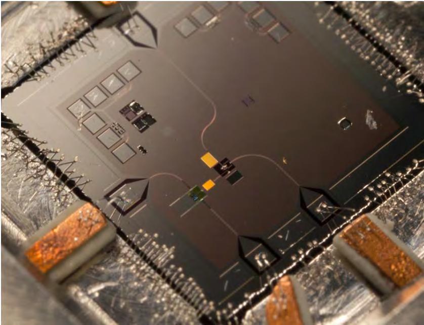
30 Mechanical resonator coupled to qubit A.D. O Connell E. Lucero phase qubit

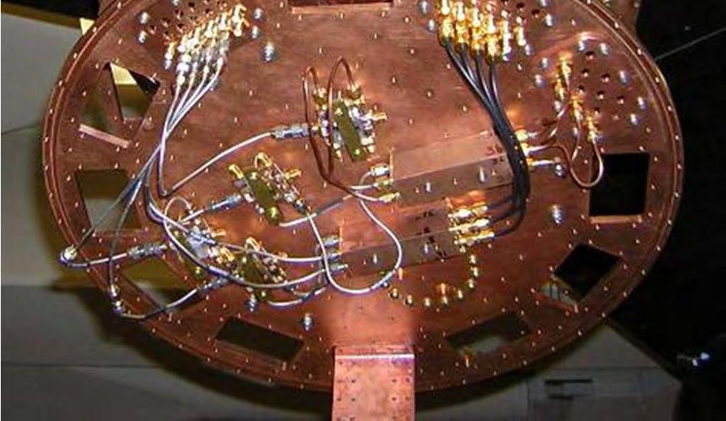

31 Dilution refrigerator
 μwaves resonance: excite qubit state frequency (GHz) 6.0 5.8 5.")
32 Qubit-mechanical resonator spectroscopy set qubit frequency apply weak microwave signal measure sweep qubit & microwave frequencies A.D. O Connell A.D. O Connell E. Lucero et al. Nature (2010) μwaves resonance: excite qubit state frequency (GHz) qubit excited state qubit tuning


33 Qubit-mechanical resonator spectroscopy frequency (GHz) level avoidance mechanical resonance f r = GHz coupling strength g =124 MHz 5.4 qubit tuning


34 Mechanical resonator ground state qubit as a quantum thermometer qubit in ground state tune into resonance, wait measure excited state probability tune qubit data
35 Exciting single phonons qubit resonator 2 e tunable 1 g Qubit in excited state Resonator ladder Qubit in ground state Resonator ladder Qubit splitting (tunable) state of system
36 Exciting single phonons Qubit off resonance (system in 0g state) Apply microwave π pulse to qubit (goes to 0e state)
37 Exciting single phonons Qubit off resonance (system in 0g state) Apply microwave π pulse to qubit (goes to 0e state) Tune qubit to resonator frequency Rabi oscillation: Transfer photon from qubit to phonon in resonator phonon in resonator 1 phonon rate: Ω
38 Exciting single phonons Qubit off resonance (system in 1g state) Apply microwave π pulse to qubit (goes to 1e state)
39 Exciting single phonons Qubit off resonance (system in 0g state) Apply microwave π pulse to qubit (goes to 0e state) Tune qubit to resonator frequency Rabi oscillation: Transfer photon from qubit to second phonon in resonator phonons in resonator 2 phonon rate: 2g 1 0 0


40 Single phonon excitations excite detuned qubit tune to resonance Rabi oscillation: Wait time, measure qubit excited state probability measure excite with one quantum tune qubit start expt theory

41 excite detuned qubit tune to resonance Rabi oscillation: Single phonon excitations excited state probability measure tune qubit start expt excited state probability stop at create one phonon theory

42 Single phonon excitations single phonon excitation: swap phonon into resonator detune & wait swap back to qubit measure qubit lifetime of excited state as expected: 6.1 ns phonon superposition: qubit in swap into resonator 0 1 wait, swap rotate to measure qubit superposition state 0 1 2

43 Half-wave coplanar resonator ( ) 2 s g n = 2 n = 1 n = 0 Photons in half-wave mode open terminations yield voltage antinodes Wavelength 2 8 mm Resonance frequency 2 7 GHz Quality factor ~10 10 Excitation lifetime ~ microseconds
44 Qubit coupled to EM resonator qubit capacitor microwave resonator Tunable Fixed qubit raising & lowering operators resonator lowering & raising operators Jaynes-Cummings Hamiltonian: coupling strength qubit-resonator photon swaps

45 Qubit coupled to EM resonator hofheinz et al. nature (2008) 25 mk


46 μwaves Qubit-resonator spectroscopy set qubit frequency, relax to weak microwave tone, measure qubit sweep qubit & microwave frequencies GHz 36 MHz hofheinz et al. nature (2008)


47 Qubit-resonator Rabi swaps excite detuned qubit tune to resonance Rabi oscillation: qubit resonator pulse qubit tune qubit & wait Excellent agreement with Jaynes-Cummings model: Rabi frequency: Δ /2 Swap probability: Δ

 Qubit in State swap with resonator Rabi")
48 Pumping photons one-by-one Pumping photons: Excite qubit from to Transfer state to resonator Repeat N times for N photons Measurement: hofheinz et al. nature (2008) Qubit in State swap with resonator Rabi frequency scales with

49 Synthesizing arbitrary states prepare and measure 0 states in resonator theory exp. Hofheinz et al. Nature (2009) Law & Eberly PRL (1996) Banaszek &Wodkiewicz PRL (1996)

50 watching schrödinger s cat die Synthesizing arbitrary states

51 Synthesizing arbitrary states / /

52

53
54

55

56

57

58
Synthesizing arbitrary photon states in a superconducting resonator
 Synthesizing arbitrary photon states in a superconducting resonator Max Hofheinz, Haohua Wang, Markus Ansmann, R. Bialczak, E. Lucero, M. Neeley, A. O Connell, D. Sank, M. Weides, J. Wenner, J.M. Martinis,
Supplementary information for Quantum delayed-choice experiment with a beam splitter in a quantum superposition
 Supplementary information for Quantum delayed-choice experiment with a beam splitter in a quantum superposition Shi-Biao Zheng 1, You-Peng Zhong 2, Kai Xu 2, Qi-Jue Wang 2, H. Wang 2, Li-Tuo Shen 1, Chui-Ping
Synthesizing Arbitrary Photon States in a Superconducting Resonator John Martinis UC Santa Barbara
 Synthesizing Arbitrary Photon States in a Superconducting Resonator John Martinis UC Santa Barbara Quantum Integrated Circuits Quantum currents & voltages Microfabricated atoms Digital to Analog Converter
Superconducting Qubits
 Superconducting Qubits Fabio Chiarello Institute for Photonics and Nanotechnologies IFN CNR Rome Lego bricks The Josephson s Lego bricks box Josephson junction Phase difference Josephson equations Insulating
Dynamical Casimir effect in superconducting circuits
 Dynamical Casimir effect in superconducting circuits Dynamical Casimir effect in a superconducting coplanar waveguide Phys. Rev. Lett. 103, 147003 (2009) Dynamical Casimir effect in superconducting microwave
Synthesising arbitrary quantum states in a superconducting resonator
 Synthesising arbitrary quantum states in a superconducting resonator Max Hofheinz 1, H. Wang 1, M. Ansmann 1, Radoslaw C. Bialczak 1, Erik Lucero 1, M. Neeley 1, A. D. O Connell 1, D. Sank 1, J. Wenner
10.5 Circuit quantum electrodynamics
 AS-Chap. 10-1 10.5 Circuit quantum electrodynamics AS-Chap. 10-2 Analogy to quantum optics Superconducting quantum circuits (SQC) Nonlinear circuits Qubits, multilevel systems Linear circuits Waveguides,
Doing Atomic Physics with Electrical Circuits: Strong Coupling Cavity QED
 Doing Atomic Physics with Electrical Circuits: Strong Coupling Cavity QED Ren-Shou Huang, Alexandre Blais, Andreas Wallraff, David Schuster, Sameer Kumar, Luigi Frunzio, Hannes Majer, Steven Girvin, Robert
SENSORS and TRANSDUCERS
 SENSORS and TRANSDUCERS Tadeusz Stepinski, Signaler och system The Mechanical Energy Domain Physics Surface acoustic waves Silicon microresonators Variable resistance sensors Piezoelectric sensors Capacitive
UNIVERSITY of CALIFORNIA Santa Barbara. Testing Quantum Mechanics in a Mechanical System: Characterizing Mechanical Resonators
 2009 1 UNIVERSITY of CALIFORNIA Santa Barbara Testing Quantum Mechanics in a Mechanical System: Characterizing Mechanical Resonators A dissertation submitted in partial satisfaction of the requirements
Mechanical quantum resonators
 Mechanical quantum resonators A. N. Cleland and M. R. Geller Department of Physics, University of California, Santa Barbara CA 93106 USA Department of Physics and Astronomy, University of Georgia, Athens,
Interaction between surface acoustic waves and a transmon qubit
 Interaction between surface acoustic waves and a transmon qubit Ø Introduction Ø Artificial atoms Ø Surface acoustic waves Ø Interaction with a qubit on GaAs Ø Nonlinear phonon reflection Ø Listening to
Circuit Quantum Electrodynamics. Mark David Jenkins Martes cúantico, February 25th, 2014
 Circuit Quantum Electrodynamics Mark David Jenkins Martes cúantico, February 25th, 2014 Introduction Theory details Strong coupling experiment Cavity quantum electrodynamics for superconducting electrical
Hybrid Quantum Circuit with a Superconducting Qubit coupled to a Spin Ensemble
 Hybrid Quantum Circuit with a Superconducting Qubit coupled to a Spin Ensemble, Cécile GREZES, Andreas DEWES, Denis VION, Daniel ESTEVE, & Patrice BERTET Quantronics Group, SPEC, CEA- Saclay Collaborating
Supplementary Information for Controlled catch and release of microwave photon states
 Supplementary Information for Controlled catch and release of microwave photon states Yi Yin, 1, Yu Chen, 1 Daniel Sank, 1 P. J. J. O Malley, 1 T. C. White, 1 R. Barends, 1 J. Kelly, 1 Erik Lucero, 1 Matteo
Superconducting quantum bits. Péter Makk
 Superconducting quantum bits Péter Makk Qubits Qubit = quantum mechanical two level system DiVincenzo criteria for quantum computation: 1. Register of 2-level systems (qubits), n = 2 N states: eg. 101..01>
NDT&E Methods: UT. VJ Technologies CAVITY INSPECTION. Nondestructive Testing & Evaluation TPU Lecture Course 2015/16.
 CAVITY INSPECTION NDT&E Methods: UT VJ Technologies NDT&E Methods: UT 6. NDT&E: Introduction to Methods 6.1. Ultrasonic Testing: Basics of Elasto-Dynamics 6.2. Principles of Measurement 6.3. The Pulse-Echo
10.5 Circuit quantum electrodynamics
 AS-Chap. 10-1 10.5 Circuit quantum electrodynamics AS-Chap. 10-2 Analogy to quantum optics Superconducting quantum circuits (SQC) Nonlinear circuits Qubits, multilevel systems Linear circuits Waveguides,
Theory for investigating the dynamical Casimir effect in superconducting circuits
 Theory for investigating the dynamical Casimir effect in superconducting circuits Göran Johansson Chalmers University of Technology Gothenburg, Sweden International Workshop on Dynamical Casimir Effect
Superconducting qubits (Phase qubit) Quantum informatics (FKA 172)
 Quantum informatics (FKA 172)") Superconducting qubits (Phase qubit) Quantum informatics (FKA 172) Thilo Bauch (bauch@chalmers.se) Quantum Device Physics Laboratory, MC2, Chalmers University of Technology Qubit proposals for implementing
Superconducting qubits (Phase qubit) Quantum informatics (FKA 172) Thilo Bauch (bauch@chalmers.se) Quantum Device Physics Laboratory, MC2, Chalmers University of Technology Qubit proposals for implementing
Dissipation in Transmon
 Dissipation in Transmon Muqing Xu, Exchange in, ETH, Tsinghua University Muqing Xu 8 April 2016 1 Highlight The large E J /E C ratio and the low energy dispersion contribute to Transmon s most significant
Honors Differential Equations
 MIT OpenCourseWare http://ocw.mit.edu 18.034 Honors Differential Equations Spring 009 For information about citing these materials or our Terms of Use, visit: http://ocw.mit.edu/terms. LECTURE 7. MECHANICAL
Optimized Surface Acoustic Waves Devices With FreeFem++ Using an Original FEM/BEM Numerical Model
 Optimized Surface Acoustic Waves Devices With FreeFem++ Using an Original FEM/BEM Numerical Model P. Ventura*, F. Hecht**, Pierre Dufilié*** *PV R&D Consulting, Nice, France Laboratoire LEM3, Université
Exploring parasitic Material Defects with superconducting Qubits
 Exploring parasitic Material Defects with superconducting Qubits Jürgen Lisenfeld, Alexander Bilmes, Georg Weiss, and A.V. Ustinov Physikalisches Institut, Karlsruhe Institute of Technology, Karlsruhe,
Strong tunable coupling between a charge and a phase qubit
 Strong tunable coupling between a charge and a phase qubit Wiebke Guichard Olivier Buisson Frank Hekking Laurent Lévy Bernard Pannetier Aurélien Fay Ioan Pop Florent Lecocq Rapaël Léone Nicolas Didier
Supplementary Methods A. Sample fabrication
 Supplementary Methods A. Sample fabrication Supplementary Figure 1(a) shows the SEM photograph of a typical sample, with three suspended graphene resonators in an array. The cross-section schematic is
Distributing Quantum Information with Microwave Resonators in Circuit QED
 Distributing Quantum Information with Microwave Resonators in Circuit QED M. Baur, A. Fedorov, L. Steffen (Quantum Computation) J. Fink, A. F. van Loo (Collective Interactions) T. Thiele, S. Hogan (Hybrid
2015 AMO Summer School. Quantum Optics with Propagating Microwaves in Superconducting Circuits I. Io-Chun, Hoi
 2015 AMO Summer School Quantum Optics with Propagating Microwaves in Superconducting Circuits I Io-Chun, Hoi Outline 1. Introduction to quantum electrical circuits 2. Introduction to superconducting artificial
Superconducting phase qubits
 Quantum Inf Process (2009) 8:81 103 DOI 10.1007/s11128-009-0105-1 Superconducting phase qubits John M. Martinis Published online: 18 February 2009 The Author(s) 2009. This article is published with open
Superconducting quantum circuit research -building blocks for quantum matter- status update from the Karlsruhe lab
 Superconducting quantum circuit research -building blocks for quantum matter- status update from the Karlsruhe lab Martin Weides, Karlsruhe Institute of Technology July 2 nd, 2014 100 mm Basic potentials
Electrical quantum engineering with superconducting circuits
 1.0 10 0.8 01 switching probability 0.6 0.4 0.2 00 P. Bertet & R. Heeres SPEC, CEA Saclay (France), Quantronics group 11 0.0 0 100 200 300 400 swap duration (ns) Electrical quantum engineering with superconducting
Quantum Optics with Electrical Circuits: Strong Coupling Cavity QED
 Quantum Optics with Electrical Circuits: Strong Coupling Cavity QED Ren-Shou Huang, Alexandre Blais, Andreas Wallraff, David Schuster, Sameer Kumar, Luigi Frunzio, Hannes Majer, Steven Girvin, Robert Schoelkopf
Josephson phase qubit circuit for the evaluation of advanced tunnel barrier materials *
 Qubit circuit for advanced materials evaluation 1 Josephson phase qubit circuit for the evaluation of advanced tunnel barrier materials * Jeffrey S Kline, 1 Haohua Wang, 2 Seongshik Oh, 1 John M Martinis
Florent Lecocq. Control and measurement of an optomechanical system using a superconducting qubit. Funding NIST NSA/LPS DARPA.
 Funding NIST NSA/LPS DARPA Boulder, CO Control and measurement of an optomechanical system using a superconducting qubit Florent Lecocq PIs Ray Simmonds John Teufel Joe Aumentado Introduction: typical
Lecture 9 Superconducting qubits Ref: Clarke and Wilhelm, Nature 453, 1031 (2008).
.") Lecture 9 Superconducting qubits Ref: Clarke and Wilhelm, Nature 453, 1031 (2008). Newcomer in the quantum computation area ( 2000, following experimental demonstration of coherence in charge + flux qubits).
Lecture 9 Superconducting qubits Ref: Clarke and Wilhelm, Nature 453, 1031 (2008). Newcomer in the quantum computation area ( 2000, following experimental demonstration of coherence in charge + flux qubits).
Final Report. Superconducting Qubits for Quantum Computation Contract MDA C-A821/0000
 Final Report Superconducting Qubits for Quantum Computation Contract MDA904-98-C-A821/0000 Project Director: Prof. J. Lukens Co-project Director: Prof. D. Averin Co-project Director: Prof. K. Likharev
Supercondcting Qubits
 Supercondcting Qubits Patricia Thrasher University of Washington, Seattle, Washington 98195 Superconducting qubits are electrical circuits based on the Josephson tunnel junctions and have the ability to
Entangled Macroscopic Quantum States in Two Superconducting Qubits
 Entangled Macroscopic Quantum States in Two Superconducting Qubits A. J. Berkley,H. Xu, R. C. Ramos, M. A. Gubrud, F. W. Strauch, P. R. Johnson, J. R. Anderson, A. J. Dragt, C. J. Lobb, F. C. Wellstood
NDT&E Methods: UT Ultrasound Generation
 CAVITY INSPECTION NDT&E Methods: UT Ultrasound Generation VJ Technologies NDT&E Methods: UT 6. NDT&E: Introduction to Methods 6.1. Ultrasonic Testing: Basics of Elasto-Dynamics 6.2. Ultrasonic Testing:
Superconducting Resonators and Their Applications in Quantum Engineering
 Superconducting Resonators and Their Applications in Quantum Engineering Nov. 2009 Lin Tian University of California, Merced & KITP Collaborators: Kurt Jacobs (U Mass, Boston) Raymond Simmonds (Boulder)
PIEZOELECTRIC TECHNOLOGY PRIMER
 PIEZOELECTRIC TECHNOLOGY PRIMER James R. Phillips Sr. Member of Technical Staff CTS Wireless Components 4800 Alameda Blvd. N.E. Albuquerque, New Mexico 87113 Piezoelectricity The piezoelectric effect is
EE C245 ME C218 Introduction to MEMS Design Fall 2007
 EE C245 ME C218 Introduction to MEMS Design Fall 2007 Prof. Clark T.-C. Nguyen Dept. of Electrical Engineering & Computer Sciences University of California at Berkeley Berkeley, CA 94720 Lecture 13: Material
Developing Quantum Logic Gates: Spin-Resonance-Transistors
 Developing Quantum Logic Gates: Spin-Resonance-Transistors H. W. Jiang (UCLA) SRT: a Field Effect Transistor in which the channel resistance monitors electron spin resonance, and the resonance frequency
Physical and Biological Properties of Agricultural Products Acoustic, Electrical and Optical Properties and Biochemical Property
 Physical and Biological Properties of Agricultural Products Acoustic, Electrical and Optical Properties and Biochemical Property 1. Acoustic and Vibrational Properties 1.1 Acoustics and Vibration Engineering
Building Blocks for Quantum Computing Part IV. Design and Construction of the Trapped Ion Quantum Computer (TIQC)
") Building Blocks for Quantum Computing Part IV Design and Construction of the Trapped Ion Quantum Computer (TIQC) CSC801 Seminar on Quantum Computing Spring 2018 1 Goal Is To Understand The Principles And
Building Blocks for Quantum Computing Part IV Design and Construction of the Trapped Ion Quantum Computer (TIQC) CSC801 Seminar on Quantum Computing Spring 2018 1 Goal Is To Understand The Principles And
Supplementary Figure 1: SAW transducer equivalent circuit
 Supplementary Figure : SAW transducer equivalent circuit Supplementary Figure : Radiation conductance and susceptance of.6um IDT, experiment & calculation Supplementary Figure 3: Calculated z-displacement
Lecture contents. Stress and strain Deformation potential. NNSE 618 Lecture #23
 1 Lecture contents Stress and strain Deformation potential Few concepts from linear elasticity theory : Stress and Strain 6 independent components 2 Stress = force/area ( 3x3 symmetric tensor! ) ij ji
Quantum computation and quantum information
 Quantum computation and quantum information Chapter 7 - Physical Realizations - Part 2 First: sign up for the lab! do hand-ins and project! Ch. 7 Physical Realizations Deviate from the book 2 lectures,
State tomography of capacitively shunted phase qubits with high fidelity. Abstract
 State tomography of capacitively shunted phase qubits with high fidelity Matthias Steffen, M. Ansmann, R. McDermott, N. Katz, Radoslaw C. Bialczak, Erik Lucero, Matthew Neeley, E.M. Weig, A.N. Cleland,
COURSE OUTLINE. Introduction Signals and Noise Filtering Sensors: Piezoelectric Force Sensors. Sensors, Signals and Noise 1
 Sensors, Signals and Noise 1 COURSE OUTLINE Introduction Signals and Noise Filtering Sensors: Piezoelectric Force Sensors Piezoelectric Force Sensors 2 Piezoelectric Effect and Materials Piezoelectric
Finite Element Analysis of Piezoelectric Cantilever
 Finite Element Analysis of Piezoelectric Cantilever Nitin N More Department of Mechanical Engineering K.L.E S College of Engineering and Technology, Belgaum, Karnataka, India. Abstract- Energy (or power)
Quantum-information processing with circuit quantum electrodynamics
 PHYSICAL REVIEW A 75, 339 7 Quantum-information processing with circuit quantum electrodynamics Alexandre Blais, 1, Jay Gambetta, 1 A Wallraff, 1,3 D I Schuster, 1 S M Girvin, 1 M H Devoret, 1 and R J
RLC Circuit (3) We can then write the differential equation for charge on the capacitor. The solution of this differential equation is
 We can then write the differential equation for charge on the capacitor. The solution of this differential equation is") RLC Circuit (3) We can then write the differential equation for charge on the capacitor The solution of this differential equation is (damped harmonic oscillation!), where 25 RLC Circuit (4) If we charge
RLC Circuit (3) We can then write the differential equation for charge on the capacitor The solution of this differential equation is (damped harmonic oscillation!), where 25 RLC Circuit (4) If we charge
Introduction to Circuit QED
 Introduction to Circuit QED Michael Goerz ARL Quantum Seminar November 10, 2015 Michael Goerz Intro to cqed 1 / 20 Jaynes-Cummings model g κ γ [from Schuster. Phd Thesis. Yale (2007)] Jaynes-Cumming Hamiltonian
Metastable states in an RF driven Josephson oscillator
 Metastable states in an RF driven Josephson oscillator R. VIJAYARAGHAVAN Daniel Prober Robert Schoelkopf Steve Girvin Department of Applied Physics Yale University 3-16-2006 APS March Meeting I. Siddiqi
Process Tomography of Quantum Memory in a Josephson Phase Qubit coupled to a Two-Level State
 Process Tomography of Quantum Memory in a Josephson Phase Qubit coupled to a Two-Level State Matthew Neeley, M. Ansmann, Radoslaw C. Bialczak, M. Hofheinz, N. Katz, Erik Lucero, A. O Connell, H. Wang,
Table of Contents. Chapter 1. Dielectricity, Piezoelectricity, Pyroelectricity and Ferroelectricity... 1
 Preface... General Introduction... xiii xvii Chapter 1. Dielectricity, Piezoelectricity, Pyroelectricity and Ferroelectricity.... 1 1.1. Crystal structure... 1 1.1.1. Crystal = lattice + pattern... 1 1.1.2.
NUMERICAL EVALUATION OF A TEFLON BASED PIEZOELECTRIC SENSOR EFFECTIVITY FOR THE MONITORING OF EARLY AGE COCRETE STRENGTHING
 NUMERICAL EVALUATION OF A TEFLON BASED PIEZOELECTRIC SENSOR EFFECTIVITY FOR THE MONITORING OF EARLY AGE COCRETE STRENGTHING Evangelos V. Liarakos Postdoctoral researcher School of Architecture, Technical
Nanomechanics II. Why vibrating beams become interesting at the nanoscale. Andreas Isacsson Department of Physics Chalmers University of Technology
 Nanomechanics II Why vibrating beams become interesting at the nanoscale Andreas Isacsson Department of Physics Chalmers University of Technology Continuum mechanics Continuum mechanics deals with deformation
Quality Factor Thickness (nm) Quality Factor Thickness (nm) Quality Factor 10
 Quality Factor Thickness (nm) Quality Factor 10") Oxygen-Terminated Fluorine-Terminated Length = 24 mm Length = 2 mm Length = 1 mm Length = 12 mm Length = 8 mm 8 mm Width, K 12 mm Width, K 1 mm Width, K 8 mm Width, K 12 mm Width, K 1 mm Width, K Supplementary
Oxygen-Terminated Fluorine-Terminated Length = 24 mm Length = 2 mm Length = 1 mm Length = 12 mm Length = 8 mm 8 mm Width, K 12 mm Width, K 1 mm Width, K 8 mm Width, K 12 mm Width, K 1 mm Width, K Supplementary
Theoretical design of a readout system for the Flux Qubit-Resonator Rabi Model in the ultrastrong coupling regime
 Theoretical design of a readout system for the Flux Qubit-Resonator Rabi Model in the ultrastrong coupling regime Ceren Burçak Dağ Supervisors: Dr. Pol Forn-Díaz and Assoc. Prof. Christopher Wilson Institute
Parity-Protected Josephson Qubits
 Parity-Protected Josephson Qubits Matthew Bell 1,2, Wenyuan Zhang 1, Lev Ioffe 1,3, and Michael Gershenson 1 1 Department of Physics and Astronomy, Rutgers University, New Jersey 2 Department of Electrical
CHAPTER 4 DESIGN AND ANALYSIS OF CANTILEVER BEAM ELECTROSTATIC ACTUATORS
 61 CHAPTER 4 DESIGN AND ANALYSIS OF CANTILEVER BEAM ELECTROSTATIC ACTUATORS 4.1 INTRODUCTION The analysis of cantilever beams of small dimensions taking into the effect of fringing fields is studied and
Transduction Based on Changes in the Energy Stored in an Electrical Field
 Lecture 7-1 Transduction Based on Changes in the Energy Stored in an Electrical Field - Electrostriction The electrostrictive effect is a quadratic dependence of strain or stress on the polarization P
Dispersive Readout, Rabi- and Ramsey-Measurements for Superconducting Qubits
 Dispersive Readout, Rabi- and Ramsey-Measurements for Superconducting Qubits QIP II (FS 2018) Student presentation by Can Knaut Can Knaut 12.03.2018 1 Agenda I. Cavity Quantum Electrodynamics and the Jaynes
The Physics of Nanoelectronics
 The Physics of Nanoelectronics Transport and Fluctuation Phenomena at Low Temperatures Tero T. Heikkilä Low Temperature Laboratory, Aalto University, Finland OXFORD UNIVERSITY PRESS Contents List of symbols
SENSOR DEVICES MECHANICAL SENSORS
 SENSOR DEVICES MECHANICAL SENSORS OUTLINE 4 Mechanical Sensors Introduction General mechanical properties Piezoresistivity Piezoresistive sensors Capacitive sensors Applications INTRODUCTION MECHANICAL
Coherent Coupling between 4300 Superconducting Flux Qubits and a Microwave Resonator
 : A New Era in Quantum Information Processing Technologies Coherent Coupling between 4300 Superconducting Flux Qubits and a Microwave Resonator Yuichiro Matsuzaki, Kosuke Kakuyanagi, Hiraku Toida, Hiroshi
Quantum Optics with Propagating Microwaves in Superconducting Circuits. Io-Chun Hoi 許耀銓
 Quantum Optics with Propagating Microwaves in Superconducting Circuits 許耀銓 Outline Motivation: Quantum network Introduction to superconducting circuits Quantum nodes The single-photon router The cross-kerr
Driving Qubit Transitions in J-C Hamiltonian
 Qubit Control Driving Qubit Transitions in J-C Hamiltonian Hamiltonian for microwave drive Unitary transform with and Results in dispersive approximation up to 2 nd order in g Drive induces Rabi oscillations
Nonlinear Oscillators and Vacuum Squeezing
 Nonlinear Oscillators and Vacuum Squeezing David Haviland Nanosturcture Physics, Dept. Applied Physics, KTH, Albanova Atom in a Cavity Consider only two levels of atom, with energy separation Atom drifts
INTRODUCTION TO SUPERCONDUCTING QUBITS AND QUANTUM EXPERIENCE: A 5-QUBIT QUANTUM PROCESSOR IN THE CLOUD
 INTRODUCTION TO SUPERCONDUCTING QUBITS AND QUANTUM EXPERIENCE: A 5-QUBIT QUANTUM PROCESSOR IN THE CLOUD Hanhee Paik IBM Quantum Computing Group IBM T. J. Watson Research Center, Yorktown Heights, NY USA
Superconducting Qubits. Nathan Kurz PHYS January 2007
 Superconducting Qubits Nathan Kurz PHYS 576 19 January 2007 Outline How do we get macroscopic quantum behavior out of a many-electron system? The basic building block the Josephson junction, how do we
Condensed Matter Without Matter Quantum Simulation with Photons
 Condensed Matter Without Matter Quantum Simulation with Photons Andrew Houck Princeton University Work supported by Packard Foundation, NSF, DARPA, ARO, IARPA Condensed Matter Without Matter Princeton
Superconducting Qubits Coupling Superconducting Qubits Via a Cavity Bus
 Superconducting Qubits Coupling Superconducting Qubits Via a Cavity Bus Leon Stolpmann, Micro- and Nanosystems Efe Büyüközer, Micro- and Nanosystems Outline 1. 2. 3. 4. 5. Introduction Physical system
Nanoscale Energy Conversion and Information Processing Devices - NanoNice - Photoacoustic response in mesoscopic systems
 Nanoscale Energy Conversion and Information Processing Devices - NanoNice - Photoacoustic response in mesoscopic systems Photonics group W. Claeys, S. Dilhair, S. Grauby, JM. Rampnoux, L. Patino Lopez,
Optomechanics and spin dynamics of cold atoms in a cavity
 Optomechanics and spin dynamics of cold atoms in a cavity Thierry Botter, Nathaniel Brahms, Daniel Brooks, Tom Purdy Dan Stamper-Kurn UC Berkeley Lawrence Berkeley National Laboratory Ultracold atomic
Circuit Quantum Electrodynamics
 Circuit Quantum Electrodynamics David Haviland Nanosturcture Physics, Dept. Applied Physics, KTH, Albanova Atom in a Cavity Consider only two levels of atom, with energy separation Atom drifts through
Lecture 10 Superconducting qubits: advanced designs, operation 1 Generic decoherence problem: Λ 0 : intended
 Lecture 10 Superconducting qubits: advanced designs, operation 1 Generic decoherence problem: Ĥ = Ĥ(p, q : Λ), Λ: control parameter { e.g. charge qubit Λ = V g gate voltage phase qubit Λ = I bias current
6.730 Physics for Solid State Applications
 6.730 Physics for Solid State Applications Lecture 5: Specific Heat of Lattice Waves Outline Review Lecture 4 3-D Elastic Continuum 3-D Lattice Waves Lattice Density of Modes Specific Heat of Lattice Specific
Non-linear driving and Entanglement of a quantum bit with a quantum readout
 Non-linear driving and Entanglement of a quantum bit with a quantum readout Irinel Chiorescu Delft University of Technology Quantum Transport group Prof. J.E. Mooij Kees Harmans Flux-qubit team visitors
FEM Simulation of Generation of Bulk Acoustic Waves and Their Effects in SAW Devices
 Excerpt from the Proceedings of the COMSOL Conference 2010 India FEM Simulation of Generation of ulk Acoustic Waves and Their Effects in SAW Devices Ashish Kumar Namdeo 1, Harshal. Nemade* 1, 2 and N.
Optimization of MEMS Piezo-Resonators
 Copyright 2013 Tech Science Press SL, vol.7, no.2, pp.129-134, 2013 Optimization of MEMS Piezo-Resonators A. Frangi 1, M. Cremonesi 1, A. Jaakkola 2 and K. Bathe 2 Abstract: Single crystal silicon MEMS
Superconducting Flux Qubits: The state of the field
 Superconducting Flux Qubits: The state of the field S. Gildert Condensed Matter Physics Research (Quantum Devices Group) University of Birmingham, UK Outline A brief introduction to the Superconducting
Sensors & Transducers 2016 by IFSA Publishing, S. L.
 Sensors & Transducers, Vol. 96, Issue, January 206, pp. 52-56 Sensors & Transducers 206 by IFSA Publishing, S. L. http://www.sensorsportal.com Collapse Mode Characteristics of Parallel Plate Ultrasonic
Solid State Physics (condensed matter): FERROELECTRICS
: FERROELECTRICS") Solid State Physics (condensed matter): FERROELECTRICS Prof. Igor Ostrovskii The University of Mississippi Department of Physics and Astronomy Oxford, UM: May, 2012 1 People: Solid State Physics Condensed
Solid State Physics (condensed matter): FERROELECTRICS Prof. Igor Ostrovskii The University of Mississippi Department of Physics and Astronomy Oxford, UM: May, 2012 1 People: Solid State Physics Condensed
Nanoacoustics II Lecture #2 More on generation and pick-up of phonons
 Nanoacoustics II Lecture #2 More on generation and pick-up of phonons Dr. Ari Salmi www.helsinki.fi/yliopisto 26.3.2018 1 Last lecture key points Coherent acoustic phonons = sound at nanoscale Incoherent
Experimental Quantum Computing: A technology overview
 Experimental Quantum Computing: A technology overview Dr. Suzanne Gildert Condensed Matter Physics Research (Quantum Devices Group) University of Birmingham, UK 15/02/10 Models of quantum computation Implementations
DESIGN AND FABRICATION OF THE MICRO- ACCELEROMETER USING PIEZOELECTRIC THIN FILMS
 DESIGN AND FABRICATION OF THE MICRO- ACCELEROMETER USING PIEZOELECTRIC THIN FILMS JYH-CHENG YU and FU-HSIN LAI Department of Mechanical Engineering National Taiwan University of Science and Technology
Slide 1. Temperatures Light (Optoelectronics) Magnetic Fields Strain Pressure Displacement and Rotation Acceleration Electronic Sensors
 Magnetic Fields Strain Pressure Displacement and Rotation Acceleration Electronic Sensors") Slide 1 Electronic Sensors Electronic sensors can be designed to detect a variety of quantitative aspects of a given physical system. Such quantities include: Temperatures Light (Optoelectronics) Magnetic
Slide 1 Electronic Sensors Electronic sensors can be designed to detect a variety of quantitative aspects of a given physical system. Such quantities include: Temperatures Light (Optoelectronics) Magnetic
INF5490 RF MEMS. LN03: Modeling, design and analysis. Spring 2008, Oddvar Søråsen Department of Informatics, UoO
 INF5490 RF MEMS LN03: Modeling, design and analysis Spring 2008, Oddvar Søråsen Department of Informatics, UoO 1 Today s lecture MEMS functional operation Transducer principles Sensor principles Methods
Chapter 2 Surface Acoustic Wave Motor Modeling and Motion Control
 Chapter 2 Surface Acoustic Wave Motor Modeling and Motion Control 1 Abstract For miniaturization of ultrasonic transducers, a surface acoustic wave device has an advantage in rigid mounting and high-power-density
Exploring Piezoelectric Properties of Wood and Related Issues in Mathematical Description. Igor Dobovšek
 Exploring Piezoelectric Properties of Wood and Related Issues in Mathematical Description Igor Dobovšek University of Ljubljana Faculty of Mathematics and Physics Institute of Mathematics Physics and Mechanics
Conventional Paper I (a) (i) What are ferroelectric materials? What advantages do they have over conventional dielectric materials?
 (i) What are ferroelectric materials? What advantages do they have over conventional dielectric materials?") Conventional Paper I-03.(a) (i) What are ferroelectric materials? What advantages do they have over conventional dielectric materials? (ii) Give one example each of a dielectric and a ferroelectric material
Conventional Paper I-03.(a) (i) What are ferroelectric materials? What advantages do they have over conventional dielectric materials? (ii) Give one example each of a dielectric and a ferroelectric material
INTRODUCTION TO SCA\ \I\G TUNNELING MICROSCOPY
 INTRODUCTION TO SCA\ \I\G TUNNELING MICROSCOPY SECOND EDITION C. JULIAN CHEN Department of Applied Physics and Applied Mathematics, Columbia University, New York OXFORD UNIVERSITY PRESS Contents Preface
Physics Curriculum Pacing Guide MONTGOMERY COUNTY PUBLIC SCHOOLS
 MONTGOMERY COUNTY PUBLIC SCHOOLS Physics Curriculum Pacing Guide 1 st 9 Weeks SOL Objectives Vocabulary 2 Days INTRODUCTION: PH.1 The student will plan and conduct investigations using experimental design
Retract. Press down D RG MG LG S. Recess. I-V Converter VNA. Gate ADC. DC Bias. 20 mk. Amplifier. Attenuators. 0.
 a Press down b Retract D RG S c d 2 µm Recess 2 µm.5 µm Supplementary Figure 1 CNT mechanical transfer (a) Schematics showing steps of pressing down and retracting during the transfer of the CNT from the
Handout 11: AC circuit. AC generator
 Handout : AC circuit AC generator Figure compares the voltage across the directcurrent (DC) generator and that across the alternatingcurrent (AC) generator For DC generator, the voltage is constant For
B I A S T E E Reducing the Size of the Filtering Hardware. for Josephson Junction Qubit Experiments Using. Iron Powder Inductor Cores.
 B I A S T E E 2. 0 Reducing the Size of the Filtering Hardware for Josephson Junction Qubit Experiments Using Iron Powder Inductor Cores. Daniel Staudigel Table of Contents Bias Tee 2.0 Daniel Staudigel
M.C. Escher. Angels and devils (detail), 1941
, 1941") M.C. Escher Angels and devils (detail), 1941 1 Coherent Quantum Phase Slip: Exact quantum dual to Josephson Tunneling (Coulomb blockade is a partial dual) Degree of freedom in superconductor: Phase and
M.C. Escher Angels and devils (detail), 1941 1 Coherent Quantum Phase Slip: Exact quantum dual to Josephson Tunneling (Coulomb blockade is a partial dual) Degree of freedom in superconductor: Phase and