The UCD community has made this article openly available. Please share how this access benefits you. Your story matters!
|
|
|
- Phyllis Chandler
- 5 years ago
- Views:
Transcription
1 Provided by the author(s) and University College Dublin Library in accordance with publisher policies., Please cite the published version when available. Title Critical speed for the dynamics of truck events on bridges with a smooth road surface Authors(s) González, Arturo; O'Brien, Eugene J.; Cantero, Daniel; Li, Yingyan; Dowling, Jason; Znidaric, Ales Publication date Publication information Journal of Sound and Vibration, 329 (11): Series Critical Infrastructure Group Publisher Elsevier Link to online version Item record/more information Publisher's statement All rights reserved Publisher's version (DOI) /j.jsv Downloaded T17:47:36Z The UCD community has made this article openly available. Please share how this access benefits you. Your story matters! (@ucd_oa) Some rights reserved. For more information, please see the item record link above.
2 Critical Speed for the Dynamics of Truck Events on Bridges with a Smooth Road Surface Arturo González 1, Eugene J. OBrien 2, Daniel Cantero 3, Yingyan Li 4, Jason Dowling 5, Ales Žnidarič 6 Abstract: Simple numerical models of point loads are used to represent single and multiple vehicle events on two-lane bridges with a good road profile. While such models are insufficiently complex to calculate dynamic amplification accurately, they are presented here to provide an understanding of the influence of speed and distance between vehicles on the bridge dynamic response. Critical combinations of speed as a function of main bridge natural frequency and meeting point of two vehicles travelling in opposite directions are identified. It is proposed that such simple models can be used to estimate the pattern of critical speeds versus dynamic amplification for heavy trucks on a bridge with a relatively smooth surface. The crossing of a threedimensional spring-dashpot truck is simulated over a bridge plate model to test this hypothesis for a range of road roughness. Further validation is carried out using the site-specific mean pattern associated to field measurements due to the passage of a truck population. The latter is found to be closely resembled by the theoretical pattern derived from simple point load models. Keywords: highway bridges; bridge loads; structural dynamics; traffic speed; dynamic amplification. 1
3 1 College lecturer, UCD School of Architecture, Landscape and Civil Engineering, University College Dublin, Newstead, Dublin 4, Ireland. phone: , fax: Professor of Civil Engineering, UCD School of Architecture, Landscape and Civil Engineering, University College Dublin, Newstead, Dublin 4, Ireland. eugene.obrien@ucd.ie, phone: , fax: Research Assistant, UCD School of Architecture, Landscape and Civil Engineering, University College Dublin, Newstead, Dublin 4, Ireland. daniel.cantero@ucd.ie, phone: , fax: Research assistant, Arup Consulting Engineers, formerly University College Dublin, Dublin, Ireland. yingyan.li@gmail.com 5 Research Assistant, UCD School of Architecture, Landscape and Civil Engineering, University College Dublin, Newstead, Dublin 4, Ireland. jason.dowling@ucd.ie, phone: , fax: Researcher, Slovenian National Building and Civil Engineering Institute, Dimiceva 12, SI-1000, Ljubljana, Slovenia. ales.znidaric@zag.si, phone: , fax:
4 Nomenclature a c C d = roughness coefficient = speed of the vehicle = damping matrix of bridge model = distance between reference masses for two vehicles travelling in opposite direction DAF E f 1 FR g I IRI j k K L M M ( ξ, τ ) = dynamic amplification factor = Young s modulus of beam = first natural frequency of the bridge = frequency ratio = acceleration due to gravity = second moment of area of cross-section = international roughness index = mode number = vehicle number = stiffness matrix of bridge model = beam length = mass matrix of bridge model = dimensionless total bending moment M R ik (, ) ξ τ = dimensionless bending moment due to interaction forces R ik M µ ( ξ, τ ) = dimensionless bending moment due to bridge inertial forces p = forcing vector 3
5 P ik PSD q j ( τ ) R ik = constant point load representing axle (or wheel) force i in vehicle k = power spectral density = normalised deflection for mode j and instantτ = dimensionless force corresponding to axle (or wheel) force i in vehicle k t x x ik = time (t = 0 when the vehicle is located at the start of the bridge) = location of section under investigation from the start of the bridge = position of axle (or wheel) force i in vehicle k on the bridge (x ik = 0 when the force is located at the start of the bridge) v(x,t) v W = deflection of the beam at position x and instant t = vector of nodal displacements and rotations = vector of nodal velocities = vector of nodal accelerations = bridge width α = speed parameter α = c 2 f L 1 δ(x) = Dirac function (impulse, also known as delta function) ε ik = parameter indicating whether the axle (or wheel) i in vehicle k is on (ε ik = 1) or off (ε ik = 0) the bridge ξ x = normalised section location on the bridge. ξ = (0 ξ 1) L ik ξ ik = normalised position of P ik along the bridge. ξ ik = (0 ξik 1) x L τ = normalised time π ct τ = L µ = mass per unit length of the bridge ζ = damping ratio 4
6 ω b = damped circular frequency of the beam ( 2 ωb = 2π f1 1 ζ ) Ω = spatial natural frequency ϑ = damping parameter ω b ϑ = f1 1. Introduction For long-span bridges, the governing traffic loading condition consists of a queue of heavy vehicles on the bridge in congested or jammed conditions [1]. In such a case, it is assumed that there is no dynamic amplification of the static load. However, for short- to medium-span bridges, the governing condition is made of a small number of vehicles travelling at high speed and inducing vibration in the bridge. There is some debate as to whether bridge loading events involving three and four high-speed trucks can be expected to feature amongst the most critical loading conditions for two-lane medium-span bridges [2]. Even so, it is clear that single truck crossings and two-truck meeting events play an important role in the assessment of the traffic load for short and medium-span bridges. While considerable research has been carried out on single truck crossing events on bridges [3-10], the dynamics of two-truck meeting events has received less attention [11-16]. Finite Element (FE) Vehicle Bridge-Interaction (VBI) models of meeting events can be constructed but are computationally expensive and they include a degree of uncertainty on many of the vehicle dynamic parameters, and in particular, those intervening in the critical meeting events. However, vehicle dynamic parameters 5
7 such as tire stiffness, suspension stiffness, damping or mass moment of inertia are less influential on the bridge response in the case of very good profiles and relatively long bridges. So, Brady and OBrien [12] have considered the case of two moving point (2P-) loads on a 1D simply supported beam. This is clearly simplistic as it fails to allow for the interaction between the truck and the bridge masses, the road surface profile and the truck suspension systems, to name just some parameters. Nevertheless, this simplified model can be used to find an explanation for the dynamic peaks generated at certain speeds. The ratio of maximum total strain to maximum static strain is defined as Dynamic Amplification Factor (DAF). The goal of this paper is to use these simple P-load models to identify the vehicle speeds that will cause maximum DAFs in bridges with a smooth surface. A smooth surface is associated here to very good and good ISO road classes [17]. The investigation focuses on critical loading events consisting of the simultaneous crossing of two 5-axle semi-trailers over a two-lane simply supported bridge. This truck class is the most common heavy goods truck configuration on European and many international roads. The P-loads simulate vehicle forces of magnitude and spacing equivalent to those of the 5-axle vehicle, and they are crossed over two types of bridge models: a 1D beam and a 2D FE isotropic plate. First, two groups of five point (5P-) loads travelling on a beam in opposite directions are used to represent the axle forces of two 5-axle trucks meeting on a bridge. This is the first analysis which considers a full range of possible vehicle speeds and truck meeting points while taking into account of the axle weight distribution in a large truck. These critical speeds are also derived for the case of two groups of 10P-loads representing wheel forces of a 5-axle truck running on a FE plate model. The critical speeds 6
8 estimated based on simulations of P-loads are compared to the results of more sophisticated 3D spring-dashpot vehicle dynamic models over a range of good road profiles and three medium span lengths. Finally, the approach is tested with strain measurements from a bridge located in Vransko, Slovenia. This field data has been collected during the European FP6 project ARCHES (Assessment and Rehabilitation of Central European Highway Structures, ) [18]. Maximum total strain was measured on the site for single events of a truck fleet using the Bridge Weigh-In- Motion system known as Si-WIM [19]. For each traffic event, the static strain was extracted from the record of measured strain through a low-pass filtering technique. Finally, the experimental DAF speed pattern associated to a given vehicle subclass is compared to the theoretical pattern derived from equivalent P-load models. 2. Simulations using moving constant loads The influence of speed on DAF due to a typical European 5-axle truck is analysed for three medium-span bridge lengths. For this purpose, the passage of a series of P-loads is simulated over two types of bridge models: a 1D beam and a 2D isotropic plate. In the bridge plate model, each P-load represents a wheel force of magnitude equal to half the static axle weight and the effect of transverse position on the critical speed is addressed. The plate width W is assumed to be 15 m, the spacing between wheels of the same axle is 2 m, and the path of the inner wheels is offset by 1 m from the bridge centreline. To get representative dimensions and relative weights between axles for a typical 5-axle European truck, weigh-in-motion data from the national road RN23 at Angers, France, is employed [2]. The recorded mean axle spacings were 3.0 m between 1 st and 2 nd axle, 5.1 m between 2 nd and 3 rd axle and 1.1 m between 7
9 consecutive axles of the rear tridem. The mean axle weights were percent, percent, percent, percent and percent of the gross weight for axles 1 to 5 respectively. The total mass of a single truck is assumed to be kg. Bridge responses and DAF-speed patterns are also obtained for an articulated 5-axle sprung model running over a range of road profiles and allowing for VBI. These simulations are used to assess the influence of road roughness and VBI on the critical speed and how they compare to that DAF-speed pattern suggested by simple P-load models. All vehicle and bridge simulation models have been built using Matlab [20]. 2.1 Dynamic model based on P-loads running in opposite directions Dynamic amplification is calculated for a series of moving point loads, P ik, representing the static component of force i exerted by vehicle k, travelling at a speed c towards one another over a simply supported bridge model of length L. The simulations are carried out using 1D beam bridge models where P ik will represent a vehicle axle force (Fig. 1(a)), and 2D plate bridge models where P ik will represent a vehicle wheel force (Fig. 1(b)). For comparison purposes, those beam and plate bridge models with the same length L, have similar mechanical properties and longitudinal frequencies of vibration. It is assumed that both vehicles have the same speed, axle weights and spacings. The ratio d/l is employed to define the relative position of the loads when they meet on the bridge, where d is given by the distance of the 3 rd axle of the second truck from the 3 rd axle of the first truck when the latter is located at midspan (this is, d is defined as shown in Fig. 1(a) when x 31 = L/2). So, d/l = 0 represents a situation where the first axle of each tridem meet at the center, d/l = 0.5 is a situation where the tridem of the second truck is just arriving on the bridge while the tridem of the first vehicle is at midspan (so both tridems will meet at one quarter 8
10 of the span), d/l = 1 is a situation where one tridem leaves the bridge at the time the other tridem is entering it, and for d/l > 1 the tridems will not meet on the bridge. [FIG. 1 HERE] The solution for the case of a constant P-load moving over a 1D simply supported beam has been described in dimensionless modal form by Frýba [21], and for two vehicle models consisting of 5P-loads each (Fig. 1(a)), it is given by: ( τ ) 2 5 q 4 j ( τ ) εikrik sin ( jπξ ik ) j q j ( τ ) j = 1, 2, q j π π ϑ = τ α k= 1 i= 1 α α τ (1) where q ( ) j τ is the j th modal coordinate of the beam deflection; j is the mode number; π ct τ is the dimensionless time ( τ = where t is time and L is bridge length ); α ( L = c 2 f L ωb where f 1 is the first natural frequency of the bridge) and ϑ ( = where ω b is damped circular frequency of the bridge) represent speed and damping parameters respectively; εik can be 1 or 0 depending if a particular load P ik is on or of the beam ik respectively; ξ ik is the dimensionless position of P ik ( ξ ik = where x ik is the position of P ik with respect to the point of entrance of the vehicle k on the bridge); and the dimensionless force R ik is given by: x L f 1 1 9
11 R ik = P ik 2 5 k = 1 i= 1 P ik i = 1,2, 5; k = 1,2 (2) Eq. (1) is solved numerically using the Runge-Kutta-Nyström method with R ik estimated as in Eq. (2). Values for q ( τ ), q ( τ ), and q ( ) j j j τ are obtained for each mode of vibration j at each instant in time, τ. The total dimensionless bending moment, M ( ξ, τ ) at normalized beam location ξ and normalized time τ can be 2 5 obtained from the sum of two dimensionless bending moments: M ( ξ, τ ) due to the applied loads and (, ) Eqs. (3), (4) and (5). M µ k= 1 i= 1 ξ τ due to the vibration of the bridge as defined in R ik 2 5 M M M µ k = 1 i= 1 R ik (3) ( ξ, τ ) = ( ξ, τ ) + ( ξ, τ ) where: M R ik ( ξ, τ ) ( ) ( ) = 4ε ikrik 1 ξik ξ for ξik ξ = = 4ε ikrik 1 ξ ξik for ξ ξik (4) and M µ ( ξ, τ ) = α q 2 j ( τ ) sin( jπξ ) 12 j (5) j= 1 Eq. (6) gives the total bending moment M (x,t) at beam position x and time t as a function of the normalized bending moment M ( ξ, τ ) defined in Eq. (3). 10
12 Pik L = k = 1 i= 1 4 ( ) ( ) 2 5, M ξ, τ M x t (6) Eqs. (1) to (6) can then be solved to find the DAFs for mid-span bending moment. The problem can be extended to a series of P-loads moving over a plate model to allow for lateral effects and torsional modes of vibration. In the latter, the meeting of two 5-axle trucks in motion is simulated with a P-load model made of a series of ten loads, P 1k, P 2k, P 3k,, P 10k, deemed to represent the forces exerted by the ten wheels of a truck k (Fig. 1(b)). The differential equations of motion of the plate model can be expressed in matrix form as in Eq. (7) and solved using a standard integration method such as Runge-Kutta. Mv + Cv + Kv = p (7) where p is the forcing vector result of distributing the P-loads to the nodes of the underlying element at each point in time, v, v and v are the vectors that define the bridge displacements, rotations and their derivatives with respect to time, and M, C and K are the mass, damping and stiffness matrixes of the bridge model respectively. In these P-load simulations, it is assumed the mass matrix of the bridge remains constant. This assumption will not be valid for extremely heavy loading events in short span bridges where high vehicle to bridge mass ratios may introduce significant changes in the mass matrix of the system. 2.2 Influence of speed and meeting point on DAF 11
13 A 25 m span simply supported bridge beam model is used first to illustrate the effect of truck speed on dynamics. The bridge properties are assumed to be those corresponding to a typical beam-and-slab concrete structure carrying two lanes of traffic, i.e., modulus of elasticity E = 35x10 9 N m -2, mass per meter µ = kg m -1 and second moment of area I = 1.39 m 4. The first natural frequency of the bridge is 4.09 Hz and damping is assumed to be negligible. The static and total midspan bending moments due to crossings of single 5P-load trucks are shown in Fig. 2 for different speeds. For the truck travelling at 90 km h -1, the arrivals of the first and second axles at midspan are hardly noticeable while the tridem arrival at midspan denotes a prominent peak with a maximum total moment of kn m and a maximum static moment of kn leading to a DAF of A sharp drop off in moment is evident as the tridem moves away from midspan and towards the end support. This effect is not surprising if it is taken into account that the tridem axles make up almost 60 percent of the total weight. Maximum total moments of and kn m result into DAFs of 1.02 and 1.07 for vehicle speeds of 70 and 110 km h -1 respectively. [FIG. 2 HERE] Fig. 3(a) shows the results of DAF versus relative position (d/l) and frequency ratio (FR) for the case of zero damping and two 5P-load truck models running in opposite directions on a simply supported beam. FR [12] is defined as the ratio of the load circular frequency (πc/l) to the first circular frequency of the bridge (2πf 1 ). If the DAF-FR-d/L relationship was derived for two 1P-loads, DAF would be uniquely defined by these two ratios, FR and d/l, and it would be valid for all bridges with the same damping, regardless the span length. The pattern of local peaks of DAF in Fig. 12
14 3(a) is quite similar to the case of two 1P-loads meeting on a 1D simply supported beam shown by Brady and OBrien [12], in spite of the difference in number of P- loads and axle weight distribution. Each peak corresponds to a matching of effects of bridge natural frequency with the speed and relative spacing of the loads. Speed (proportional to FR) and the parameter d, can compensate for each other in achieving the time match of constructive/destructive interference that results into these peaks. The amplification of the maximum static response is related to the periodic nature of the dynamic forces, i.e., there are critical speeds that result into bridge inertial forces causing a peak dynamic moment at the same instant the peak static moment takes place. For d/l > 0.5, the first tridem has passed midspan before the second tridem has reached it, and there is a clear pattern of repeating peaks. Statically, this does not tend to be the most critical case but it is significant in statistical calculations of loading probabilities. For any given speed within this region, the peaks are of equal height as no damping has been considered. When damping is allowed for, the peaks corresponding to d values in excess of 0.5L, are reduced as might be expected. This is illustrated in Fig. 3(b) for the same bridge, but allowing for 5 percent damping ratio (ζ = 0.05). As in the case of zero damping, there appears to be a pattern of peaks linked in pairs. [FIG. 3 HERE] When a single 5-axle truck is modelled using a 10P-load model travelling over one lane of a 2D isotropic plate model, it is possible to evaluate the transverse variation of moments for a given longitudinal section. The longitudinal properties of the plate model are selected to match those of the 1D simulation in Fig. 2. Figs. 4(a) and (b) are 13
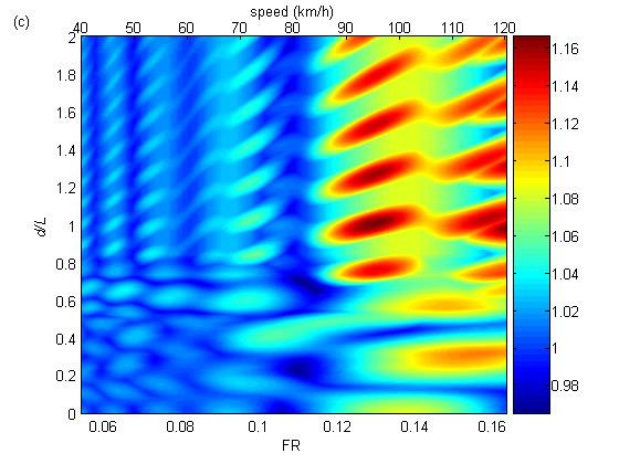
15 the maximum total and the maximum static moments across the midspan section. Fig. 4(c) is the DAF-speed pattern for each transverse location of the midspan section. DAF is obtained dividing the z-ordinate of Fig. 4(a) by the corresponding ordinate of Fig. 4(b). The critical speeds causing large DAFs at midspan vary between 90 and 105 km h -1 depending on the transverse location. [FIG. 4 HERE] DAF and maximum total moment are also obtained as a function of d/l and speed when two 10P-load models are driven over different lanes of a 25 m simply supported plate model with a 1.5 percent modal damping. Figs. 5(a) to 5(d) show the DAF and total moment values corresponding to three specific transverse locations within the bridge midspan cross-section, i.e., the bridge centreline and 6 m to the left and to the right of the bridge centreline. The critical static loading cases are those where the two trucks meet near midspan. So, Figs. 5(b), (d) and (f) show that the most important moments develop for d/l < 0.5. Hence it is reasonable to assume that the peaks of greatest interest are in the range of d/l 0.5, even although higher DAFs develop outside this region. It can be seen that maximum DAFs are normally associated to small values of total bending moments. In the d/l 0.5 region, there are two important zones: a peak in the interval 0.2 d/l 0.4 and FR between 0.14 and 0.16 (A FR of 0.15 is associated to a speed 2 FR = 2x4.09x25x0.15 = 30.7 m s -1 or km h -1 ), and a peak at d/l = 0 corresponding to both tridems meeting at the centre and FR between 0.12 and 0.14 (A FR of 0.13 is associated to 96 km h -1 ). It can be seen that the simplified 1D P-load model of Fig. 1(a) used to generate Fig. 3(a) is sufficient to capture the overall pattern due to a 2D P-load model. There are only 14
16 small differences between Figs. 3(a) and 5(a) regarding the level of dynamic amplification and the transverse location under investigation. [FIG. 5 HERE] The maximum total moment generally decreases as the transverse location gets closer to the edges of the plate model. It is interesting to observe there is not an identical behaviour in the points symmetrically located with respect to the bridge centreline (Figs 5(a) and 5(e)). For the results of the transverse location in Figs. 5(a) and (b) and for any value of d/l larger than 0.8 (i.e., both tridems meeting far from the midspan section), there appears to be a constant value of total moment and DAF for a given vehicle speed (or FR), that does not appear in the symmetric transverse location given in Figs. 5(e) and (f). This region of constant values is due to the fact that the maximum total moment will occur when the tridem of the first vehicle is driving over the same lane where the bending moment is being investigated. Nevertheless, the symmetric transverse location will experience maximum moments when the tridem of the second vehicle drives over its side of the cross-section (Figs. 5(e) and (f)), leading to values affected by pre-existing vibrations induced by the first vehicle (only very large values of d/l could facilitate the bridge to completely damp the vibrations of the first vehicle out). This phenomenon of an initial vibratory condition of a bridge prior to traffic loading has been investigated in detail by Rattigan et al [22]. Fig. 6 illustrates the maximum static bending moment, maximum total bending moment and DAF versus d/l that has been found within a highway speed range (40 to 120 km h -1 ). Here, DAF has been defined as the maximum total moment divided by 15
17 the maximum static moment taking into account seven transverse locations across the midspan section (i.e., at the bridge centreline and at 2, 6 and 7.5 m from the centreline on both sides). The maximum total and maximum static moments may not correspond to the same transverse location. It can be seen the largest moment takes place for d/l = 0, when both tridems meet at midspan, and the analysis in the following sections will focus on this critical meeting point. [FIG. 6 HERE] 2.3 Influence of bridge length on DAF To encompass a typical range of designs and to analyse the influence of other axle spacing to span length ratios, two additional spans are considered, 17 m and 35 m, all 15 m wide. The 17 m bridge was assumed to be of beam-and-slab construction, i.e., precast Y-beams with an in-situ slab [23,24], µ = kg m -1 and I = 0.49 m 4 (f 1 = 5.82 Hz). The 35 m span was assumed to be of similar form but with super-y beams (µ = kg m -1, I = 3.42 m 4, f 1 = 3.01 Hz). Due to the nature of Eq. (1), for a bridge with a given span length and a P-load meeting event with fixed axle spacings and axle weight distribution, the DAF-FR-d/L contour plots are identical regardless the bridge section properties. I.e., if the 17 m bridge was assumed to be of solid construction (precast inverted T-beam with in-situ concrete fill), and the mass per meter and second moment of area were µ = kg m -1 and I = 0.77 m 4 respectively (f 1 = 4.99 Hz), the DAF-FR-d/L contour plot would be the same as the one given for a 17 m beam-and-slab construction slab. When analyzing DAFs, the critical FR values, as opposed to critical speeds, have the benefit of remaining constant for a given span length. However, the critical speed associated to the dynamic peaks will vary since the 16
18 two bridge types have different natural frequencies. I.e., in the 17 m bridge, a typical speed of 80 km h -1 corresponds to a FRs of and for the beam-and-slab and solid cross-sections respectively. Beam and isotropic plate models have been built for the 17 m solid slab, and the 17 m, 25 m and 35 m beam-and-slab simply supported bridges. Table 1 shows the values used in the four plate models under investigation. In all plate models, it has been assumed a 1.5 percent modal damping applied to all modes of vibration. [TABLE 1 HERE] Figs. 7(a) and (b) show the speeds causing higher DAF for the loading case corresponding to both tridems meeting at the center (d/l = 0) and the three bridge spans being analyzed using beam and plate bridge models respectively. Although a 1D beam model is too simple to find DAF directly, here it is shown to give a good approximation of the critical vehicle speeds found in isotropic plate models. Larger differences are expected between both models when allowing for a lower stiffness in the transverse direction than in the longitudinal direction and a higher influence of the transverse modes of vibration. These P-load based simulations can clearly save computational time for a series of more elaborate analyses to be focused on the critical speeds. [FIG. 7 HERE] For the case of the 35 m beam model, the maximum DAF is 1.09 and it takes place for FR = 0.129, corresponding to a critical speed of 98 km h -1. The 35 m plate model 17
19 gives a maximum DAF of 1.07 for the same FR of (98 km h -1 ). The 25 m bridge beam and plate models both have critical FRs of which corresponds to a speed of 98 km h -1 (as result of covering for many possible transverse locations, the plate model also provides a second peak at 105 km h -1 that it is not as significant in the beam model) and although higher DAFs can be achieved at FR over (speeds over 150 km h -1 ), they are unlikely to occur in a critical two-truck meeting event. In the 17 m bridge, both beam and plate bridge models identify an intermediate critical speed at about FR = This FR corresponds to a vehicle speed of 84 and 98 km h - 1 for the solid and beam-and-slab cross sections respectively. Then, for the beam model, DAF decreases down to a point of about FR = 0.163, and then DAF increases again reaching at FR = (corresponding to vehicle speeds of 113 km/h and 133 km h -1 for the solid and beam-and-slab cross bridge sections respectively) the same level of DAF as the intermediate critical FR of For values of FR higher than 0.185, the pattern shows a continuous increase in DAF in both beam and bridge models, so the speed limit is likely to define one of the critical speeds of the pattern. While Fig. 7 shows the DAF resulting from taking the maximum total and maximum moment across the plate width regardless its transverse location, Fig. 8 shows DAF- FR patterns for two individual transverse locations: the bridge centreline and 6 m from the centreline. The critical speed is sensitive to the transverse location as it was observed for one 5-axle truck (Fig. 4). For both the 25 and 35 m bridges, the critical speeds for the centreline and 6 m from centreline locations are 100 km h -1 and 94 km h -1 respectively. In the case of the 17 m bridge, the intermediate critical FR for the centreline is (88 km h -1 if a solid slab or 103 km h -1 if a beam-and-slab construction) while the other location has an intermediate critical FR of (82 km 18
20 h -1 and 96 km h -1 for solid slab and beam-and-slab constructions respectively). For all bridge lengths, there is a difference of about 6 km h -1 between the critical speeds associated to the two transverse locations. [FIG. 8 HERE] 2.4 Influence of differences in vehicle speeds For the contour plot of DAF in Fig. 9(a), the meeting point is fixed at d/l = 0 and vehicle speeds are varied for two trucks driving in opposite directions on a two-lane 25 m plate model. The results are symmetric with respect to the 45º line that represents both vehicles travelling at the same speed. Therefore, there is a clear correspondence between a horizontal/vertical section and a section at 45º. The DAF patterns of the first vehicle are shown for fixed speeds of the second vehicle of 55, 70, 85 and 100 km h -1 in Fig. 9(b). The four patterns are found to be very similar to that pattern of both vehicles travelling at the same speed, with the highest DAFs occurring for the fixed speed of 100 km h -1. From Fig. 9(b), it is possible to obtain critical speeds for the first vehicle of 98, 105, 96, and 98 km h -1, when the speeds of the second vehicle are fixed to 55, 70, 85 and 100 km h -1 respectively. These values of critical speeds are very close to the 98 km h -1 obtained in Fig. 7 using the same speed in both vehicles. [FIG. 9 HERE] 2.5 Influence of the road profile 19
21 The response of a 25 m isotropic plate to the crossing of an articulated 5-axle sprung vehicle model allowing for VBI, is used here to test the ability of the P-load model in predicting the critical speeds. The bridge has the mechanical characteristics defined in Table 1. The truck has the same axle spacing and weight distribution used throughout Section 2. The P-loads represent the static weights of the wheels where the paths of the inner and outer wheels are located at 1 and 3 m respectively from the bridge centreline. The DAF-FR pattern suggested by the P-loads has been given in Fig. 4(c). Nevertheless, this pattern ignores the variation in dynamic forces caused by the interaction with the road surface and the bridge. A truck FE dynamic model made of a set of lumped masses, springs and dampers is employed to assess how far the P-load critical speed is from the true critical speed. This vehicle model has 15 independent degrees of freedom: vertical displacement and rotations of the tractor body mass, rotations of the trailer body mass, and the vertical displacements of the 10 axle masses (Fig. 10). A detailed description of the equations of motion governing the response of this mathematical model can be found in Cantero et al [25]. Static axle weights and axle spacings match those defined for the P-load model. A Montecarlo simulation is carried out varying the truck dynamic parameters based on assumed normal distributions for the suspension and tire systems as defined in Table 2 [26-29]. There are two types of suspensions and the values and variability are different for steer, drive and trailer axles. The dynamic interaction between bridge and truck is implemented in Matlab using an iterative procedure described by Green et al [6] and Cantero et al [30]. The iterative procedure has been found in agreement with an alternative VBI procedure based on Lagrange multipliers using 20
22 MSc/NASTRAN [11], and it has been preferred because of its flexibility and savings in computational time. [FIG. 10 HERE] [TABLE 2 HERE] The magnitude of the vehicle forces strongly depends on the road unevenness. In this paper, the road profile is assumed to be a random process described by a power spectral density (PSD) function that depends on the road condition and it is implemented using the inverse Fast Fourier Transform as described by Cebon and Newland [31]. The profiles are also passed through a moving average filter to emulate the tyre contact patch [29]. The road condition is characterised by the roughness coefficient a (m 3 cycle -1 ) or value of the spectral density at the spatial frequency 1 discontinuity Ω = cycle m -1. Values of the PSD for each spatial natural frequency 2π (Ω) are directly proportional to a and inversely proportional to (2πΩ) 2 according to ISO specifications [17]. So, the intervals a < 8x10⁻⁶ and 8x10⁻⁶ a 32x10-6 fall within very good and good road classes respectively, which would be expected in well maintained highway surfaces. Fig. 11 illustrates one of the generated random road carpets for a roughness coefficient of 8x10⁻⁶ m 3 cycle -1. Each vehicle wheel has a path that is selected from the carpet. [FIG. 11 HERE] Profiles with roughness coefficients of 1x10⁻⁶, 4x10⁻⁶, 8x10⁻⁶, 16x10-6 and 32x
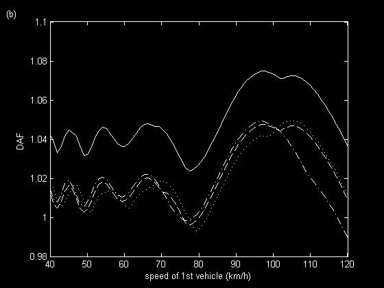
23 m 3 cycle -1 are used to obtain the bridge response to the single 5-axle truck event. 100 m of approach length are allowed to initially excite the vehicle before entering the bridge. Therefore, 8384 different truck dynamics and road profiles are generated for each roughness coefficient a (a total of simulations for all five roughness coefficients being tested). The profile is varied in each simulation by randomly generating the array of numbers defining the phase of each road wavelength. This variation is important because it is not only the height of the road irregularities but also its specific location on the bridge that affect the bridge dynamic response [32]. Figs. 12(a) and (b) show the results of the Monte Carlo simulation for the lowest and higher roughness coefficients respectively. Each point represents the ratio of the maximum total moment to the maximum static moment found at the midspan section. The solid line represents the mean pattern, which has been calculated using a moving average of 100 points. In spite of the variation in road irregularities and truck dynamics, there is a DAF-speed pattern. This pattern is clearer for the smooth profile (Fig. 12(a)) that exhibits less scatter than the rough profile of Fig. 12(b)). Fig. 12(b) contains more uncertainty in the level of dynamic amplification due to a strong influence of road roughness and truck dynamics, but if there is sufficient number of points, an underlying mean pattern can still be detected. [FIG. 12 HERE] Fig. 13 compares the DAF-speed pattern by P-load and the mean DAF-speed patterns by sprung models for the five roughness coefficients under investigation. Although the level of dynamic amplification varies, the pattern remains and the critical speeds are only slightly shifted as the roughness coefficient varies. There is 22
24 also a widening of the peaks as the road roughness increases. The height and location of the road irregularities will become more important in DAF-speed patterns for poor profiles and short bridges. But for the 25 m bridge of Fig. 13, once the roughness coefficient remains below the good condition boundary, there is a critical speed of about 105 km h -1 using sprung models, that can be closely approximated by the P-load model (two peaks in the P-load pattern with critical speeds of 99 km h -1 and 105 km h - 1 ). It must be noted the similarities between the DAF-speed patterns predicted by a P-load model for a single 5-axle truck (Fig. 13) and for a two 5-axle truck meeting event with d/l = 0 (Fig. 7(b)). As the road profile gets poorer and the bridge span gets shorter, it is expected that the P-load model will gradually lose accuracy in the prediction of a pattern that will become governed by the road profile. Deng and Cai [33] investigated the dynamic amplification due to the crossing of an AASHTO HS20-44 truck travelling over multi-girder concrete bridges for seven speeds between 30 and 120 km/h, five span lengths between 9.14 and m, and ISO road classes varying from very good to very poor condition. They showed graphs of impact factors versus speed where patterns can also be identified. It can be seen how these patterns were altered by road roughness, and how the differences appeared to be more significant for shorter bridge spans. [FIG. 13 HERE] Fig. 14 shows the bending moments at the midspan bridge centreline for a critical speed of 105 km h -1 due to the P-load model and to a random sprung model on the road carpet of Fig. 11. This figure illustrates why the P-load model is able to predict the pattern found in more complex VBI models with a good road profile. The total 23
25 moment by both models oscillate around the bridge static response. These dynamic oscillations may have different amplitudes depending on the road roughness and dynamic characteristics of the vehicle, but for a given vehicle speed, the peaks of the oscillations hardly vary their location with respect to the location of the maximum static. As result, the P-load model is able to identify the speeds when the maximum dynamic peak develops over the location of the maximum static moment with the potential of leading to a large DAF. [FIG. 14 HERE] 3. Experimental testing Strain measurements due to the passage of traffic have been collected in a bridge located in Vransko, Slovenia, during the ARCHES project [18]. SiWIM [19] has been employed to provide vehicle speed, number of axles, weights and axle spacings for each traffic event using the strain measured under the bridge soffit. This modern Bridge Weigh-In-Motion system can also estimate the maximum static strain using a low-pass filter that removes the dynamic component of the measured strain. The ratio between maximum measured strain and maximum static strain gives a value of DAF for the crossing of each vehicle that can be used to obtain the mean DAF-speed pattern of a particular truck population. 3.1 Field measurements The bridge is a two-lane simply supported structure with traffic in opposite directions and 24.8 m span length. Single events of two modes of a 2-axle rigid truck population 24
26 were selected for monitoring of their DAF and speed because of its high number of occurrences on the Vransko site. A total of 7603 and axle trucks were recorded for the light and heavy modes respectively between the 25 th September 2006 and the 21 st November Mean and standard values for axle spacings and weights are defined in Table 3. [TABLE 3 HERE] Fig. 15 shows the histograms of speed for the two truck modes under investigation. As expected, lighter vehicles tend to travel faster as shown by the higher number of occurrences of mode 1 over mode 2 between 100 and 120 km h -1. [FIG. 15 HERE] The road profile was measured with the ZAG-VP longitudinal profilometer [18]. Measurements were performed on the normal right wheel path in each lane. They started 80 m before the bridge and were extended for 80 m after leaving the bridge. The 150 m IRI (International Roughness Index) index is typically used to assess roughness of the pavement on the network level and IRI 150 of 2.96 and 2.04 mm m -1 were obtained for the right and left lanes respectively. While simulations normally generate relatively uniformly uneven road profiles, the measured road profiles address the major unevennesses that often occur around the expansions joints, either due to their damage or due to the settlements of the pavement just before or after the bridge. Experiences show that the residual displacements of soil near the bridge can often, in the first years after the bridge construction, initiate bumps that increase the 25
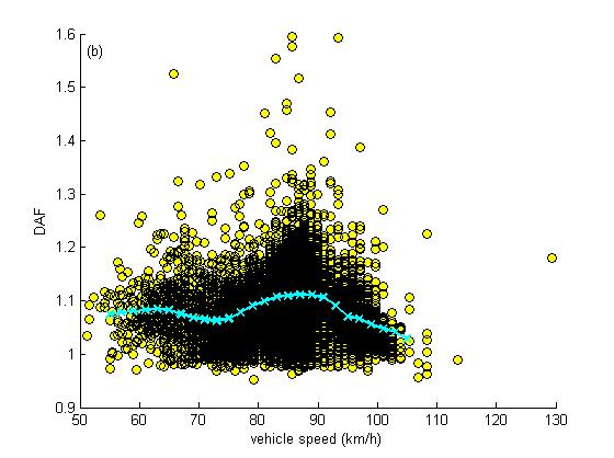
27 DAF values. These were observed on the 10-year old Vransko bridge, particularly in the right lane (Fig. 16(a)). However, due to the length of the section, IRI 150 filters out the bumps and other major unevennesses around and on the bridge that excite the bridge response and, as a result, increase the DAF values. Thus, IRI indices were also calculated on shorter sections, i.e., over 20 meter sections (IRI 20 ) and over 10 meter sections (IRI 10 ) to illustrate the local conditions. Fig. 16 shows the measured profiles and the calculated values of IRI 20 and IRI 10 for each lane.. The bridge has not been resurfaced since it was constructed and it has values of of IRI 20 = 3.30 and IRI 10 = 5.20 mm m -1 in the right lane of the bridge, and IRI 20 = 2.20 and IRI 10 = 2.83 mm m -1 in the left lane (equivalent to a roughness coefficient a below 32x10-6 m 3 cycle -1 ). These IRI values fall within the range of good road profiles investigated in the Section 2.5. [FIG. 16 HERE] The points in Fig. 17 represent all the measured DAFs. The figure also shows the mean DAF-speed pattern, which is obtained from averaging every 10 km h -1 while progressing in steps of 2 km h -1. [FIG. 17 HERE] It would be expected to have a better definition of the pattern in those speed regions where there is a more dense truck population (i.e., between 80 and 90 km h -1 according to histogram of Fig. 15). Fig. 18 compares both modes for three sample sizes: the full sample size, and the first 2/3 and 1/3 of the sample entering the bridge. 26
28 It can be seen how the pattern converges faster towards the pattern of the full sample in those intermediate speed regions with many truck occurrences. It is evident a minimum number of trucks is needed to characterise the mean DAF-speed pattern of a given sample and an extended measurement period would be needed to characterize the least frequent lower and upper speed ranges. It can also be observed there are only small differences in the DAF-speed pattern of both truck modes. [FIG. 18 HERE] 3.2 Theoretical and experimental critical speeds The mean values for axle spacing and axle weights from Table 3 are used as parameters for a 4P-load vehicle model representing the 4 wheels of a 2-axle rigid truck. An orthotropic bridge plate model is built based on the experimentally validated FEM of the Vransko bridge described by Cillian et al [34]. The longitudinal and transverse moduli of elasticity of the bridge model are 3.5x10 10 and 1.4x10 10 N m- 2 respectively, and the first longitudinal and transverse modes of vibration have frequencies of 5.32 Hz and Hz respectively. Numerical simulations of the bridge response of the Vransko bridge model to moving P-loads are used to predict the critical speeds associated to the 2-axle truck using Eq. (7). The patterns due to the P-load model associated to the 2 modes under investigation are compared to those found experimentally in Fig. 19. For the heavy 2-axle truck mode, the P-load model correctly estimates the maximum critical speed in 87 km h -1, while for the light mode there is a small discrepancy with the P-load model giving a critical speed of 86 km h -1 compared to the measured 89 km h -1. Other features of the pattern are recognised in the theoretical model, i.e., both experimental and theoretical patterns have a higher trough to the left of the central peak than the trough to the right of the DAF peak. 27
29 [FIG. 19 HERE] The dynamic patterns of both truck modes are very similar but they appear slightly shifted with speed. The direction of the shift differs in the theoretical and experimental patterns. It must be noted that the population of the light truck mode is smaller than the heavy mode, and the measured mean pattern may not be as reliable as for the heavy mode. Therefore, there will generally appear differences between the measured and predicted pattern to some extent as a result of a limited sample size within some speed ranges, relatively large standard deviations of gross weights and their distribution (there will be a different DAF-speed response for each specific vehicle), the road roughness, variations in the lateral position of the vehicle or discrepancies between the mathematical bridge model and reality. Nevertheless, it has been shown that a simulation model based on P-loads is a valuable tool to approximate the location of peaks and troughs found in an experimental pattern. 4. Conclusions When simulating the dynamic interaction between a vehicle and a bridge, there are many uncertainties involving parameters of difficult estimation on the field. A model consisting of a series of moving constant point loads (P-loads) has been employed here to identify the critical speeds that place the bridge under highest total moment. This simple model only takes into account bridge dynamics, but if the road profile was relatively smooth, it can be used to predict the worst speed scenarios derived from complex VBI models or from bridge measurements. 28
30 The values and spacings of the P-loads must be adjusted to be in agreement with the static weights and spacings of the vehicles being modeled. Contour plots of maximum dynamic amplification versus frequency ratio and normalized relative distance between trucks have been obtained using simulations of P-loads over two types of bridge models: a 1D beam and a 2D FE isotropic plate. 2D/3D bridge models are necessary to allow for the effect of the transverse position of the vehicle and to analyse the load effect at different transverse locations across the width. Nevertheless, it has been shown that a 1D beam model may provide a first approximation of the critical speeds. Critical meeting events of typical 5-axle trucks travelling in opposite directions have been simulated over four medium-span bridges. Truck speeds have been varied resulting into contour plots that reveal a clear pattern consisting of a series of dynamic peaks and troughs associated to different speeds and distances between trucks. As speed increases, the peaks tend to be wider and higher, i.e., more significant dynamics. This trend is limited by the maximum speeds to be expected on a motorway, and so, four main critical peak speeds have been identified within a motorway speed range. If a frequency ratio parameter relating vehicle speed and bridge frequency was employed, the resulting DAF-FR pattern is found to be less sensitive to changes in span length than the DAF-speed pattern. Therefore, for a given span length and traffic event, the critical speed will vary with the properties of the cross-sectional bridge, but the critical FR relating vehicle speed and bridge natural frequency will remain the same. Then, the critical speeds have been obtained for a more realistic scenario using complex spring-dashpot truck models and allowing for interaction with the road and 29
31 the bridge. The bridge has been idealised as an isotropic plate model. The 5-axle vehicle has been modelled as a 15 degree-of-freedom model consisting of mass, rigid and spring elements. Truck dynamic properties have been varied using MonteCarlo simulation, and road carpets have been randomly generated using power spectral density functions as defined by ISO standards. A large sample of very good and good ISO road profiles have been used to derive their associated DAF-speed patterns. In order to compare results from the VBI model to the P-load approach, allowance has been made for accurate transverse location of the P-load model on the bridge. It has been shown that for medium-span bridges, the P-load model can predict the number of peaks and troughs in the pattern and those critical speeds once the spatial geometric mean remains within very good and good road classes. The smoother the profile, the more accurate the predicted DAF-speed pattern becomes. For traffic events made of other vehicle configurations, the values and spacings of the P-loads will need to be readjusted and the number of peaks and their location will clearly be different. Finally, a field trial has been carried out on a bridge in Slovenia with the aim of comparing the critical speeds that a P-load model would suggest to those measured on site. Maximum total strain, static strain, vehicle speed, weights and axle spacings have been collected using Bridge Weigh-In-Motion technology. This data has been used to obtain the experimental DAF-speed patterns for two 2-axle truck populations. Then, a theoretical FE plate model of the bridge has been built based on bridge drawings and measurements, and a 4P-load model has been defined for each vehicle population based on the average measured wheel static weights and axle spacings. It has been 30
32 shown how the experimental critical speeds have compared well with those peaks in the theoretical DAF-speed pattern using a simple P-load model. Acknowledgments The authors would like to express their gratitude for the support received from the 6th European Framework Project ARCHES ( ) towards this investigation. References [1] N.J. Ricketts, J. Page, Traffic data for highway bridge loading, Transport Research Laboratory, TRL Report 251, [2] S. Grave, Modelling of site-specific traffic loading on short to medium span bridges, PhD Thesis, Department of Civil Engineering, Trinity College, Dublin, Ireland, [3] S.P. Brady, E.J. OBrien, A. Žnidarič, The effect of vehicle velocity on the dynamic amplification of a vehicle crossing a simply supported bridge, ASCE Journal of Bridge Engineering 11(2) (2006) [4] DIVINE Programme, Dynamic interaction of heavy vehicles with roads and bridges. DIVINE Concluding Conference, Ottawa, Canada, June, [5] A. Greco, A. Santini, Dynamic response of a flexural non-classically damped continuous beam under moving loadings, Computers and Structures 80 (2002) [6] M.F. Green, D. Cebon, D.J. Cole, Effects of vehicle suspension design on dynamics of highway bridges, ASCE Journal of Structural Engineering 121(2) (1995)
33 [7] M. Fafard, M. Bennur, M. Savard, A general multi-axle vehicle model to study the bridge-vehicle interaction, Engineering Computations 15(5) (1997) [8] C. Liu, D. Huang, T.L. Wang, Analytical dynamic impact study based on correlated road roughness, Computers and Structures 80 (2002) [9] M. Olsson, On the fundamental moving load problem, Journal of Sound and Vibration 154(2) (1991) [10] D. McLean, M.L. Marsh, Dynamic impact factors for bridges, NCHRP synthesis 266, Transportation Research Board, National Research Council, [11] A. González, P. Rattigan, E. OBrien, C. Caprani, Determination of bridge lifetime DAF using finite element analysis of critical loading scenarios, Engineering Structures 30(9) (2008) [12] S.P. Brady, E.J. OBrien, The effect of vehicle velocity on the dynamic amplification of two vehicles crossing a simply supported bridge, ASCE Journal of Bridge Engineering 11(2) (2006) [13] J.L. Humar, A.H. Kashif, Dynamic response analysis of slab-type bridges, ASCE Journal of Structural Engineering 121(1) (1995) [14] P.H. Kirkegaard, S.R.K. Nielsen, I. Enevoldsen, Heavy vehicles on minor highway bridges Calculation of dynamic impact factors from selected crossing scenarios. Paper No. 172, Dept. of Building Technology and Structural Engineering, Aalborg Universtity, Aalborg, Denmark, ISBN R9722, [15] Y.B.Yang, S.S. Liao, B.H. Lin, Impact formulas for vehicles moving over simple and continuous beams, ASCE Journal of Structural Engineering 121(11) (1995) [16] X.Q. Zhu, S.S. Law, Dynamic load on continuous multi-lane bridge deck from moving vehicles, Journal of Sound and Vibration 251(4) (2002)
34 [17] International Organization for Standardization ISO 8608, Mechanical vibration - road surface profiles - reporting of measured data, [18] ARCHES Programme, Assessment and rehabilitation of central European Highway Structures. WP 2: Structural Assesment and Monitoring, EU 6 th Framework, Accessed December 9, [19] A. Žnidarič, I. Lavrič, J. Kalin, Measurements of bridge dynamics with a bridge weigh-in-motion system, Proceedings of the Fifth International Conference on Weigh-In-Motion, Jacob B, Obrien E.J., O Connor A., Bouteldja M Eds, ISTE Publishers, Paris, France, 2008, pp [20] The Mathworks, Inc., Using MATLAB, Version 6, USA, [21] L. Frýba, Vibration of Solids and Structures under Moving Loads, Noordhoff International Publishing, Groningen, The Netherlands, 1972, re-issued [22] P. Rattigan, A. González, E. O Brien, The influence of pre-existing vibrations on the dynamic response of medium-span bridges, Canadian Journal of Civil Engineering 36(1) (2009) [23] H.P.J. Taylor, L.A. Clark, C.C. Banks, The Y-beam: a replacement for the M- beam in beam-and-slab bridge decks, The Structural Engineer 68 (23) (1990) [24] H.P.J. Taylor, The precast concrete bridge beam: the first 50 years, The Structural Engineer 76 (21) (1998) [25] D. Cantero, E.J. OBrien, A. González, Modelling the vehicle in vehicleinfrastructure dynamic interaction studies, Proceedings of the Institution of Mechanical Engineers, Part K, Journal of Multi-body Dynamics 224 (2010) doi: / JMBD228 [26] J.Y. Wong, Theory of Ground Vehicles, John Wiley & Sons,
35 [27] T.T. Fu, D. Cebon, Analysis of a truck suspension database, International Journal of Heavy Vehicle Systems 9:4 (2002) [28] P.H. Kirkegaard, S.R.K. Nielsen, I. Enevoldsen, Heavy vehicles on minor highway bridges Dynamic modelling of vehicles and bridges. Report in Department of Building technology any and Structural Engineering, Aalborg University, ISSN R9721, December, [29] N.K. Harris, E.J. OBrien, A. González, Reduction of bridge dynamic amplification through adjustment of vehicle suspension damping, Journal of Sound and Vibration 302:3 (2007) [30] D. Cantero, E.J. OBrien, A. González, B. Enright, C. Rowley, Highway bridge assessment for dynamic interaction with critical vehicles, 10th International Conference on Safety, Reliability and Risk of Structures, ICOSSAR 2009, Furuta, Frangopol & Shinozuka, Taylor & Francis eds, Osaka, Japan, 2009, pp [31] D. Cebon, D.E. Newland, Artificial generation of road surface topography by the inverse F.F.T. method, Vehicle System Dynamics 12:1 (1983) doi: / [32] Y.Y. Li, E.J. OBrien, A. González, The development of a dynamic amplification estimator for bridges with good road profiles, Journal of Sound and Vibration 293:1-2 (2006) [33] L. Deng, C.S. Cai, Development of dynamic impact factor for performance evaluation of existing multi-girder concrete bridges, Engineering Structures 32 (2010) [34] C.W. Rowley, E.J. OBrien, A. González, A. Žnidarič, Experimental testing of a moving force identification bridge weigh-in-motion algorithm, Experimental Mechanics 49:5 (2009) doi: /s
36 Fig. 1 Simple P-load simulation of two 5-axle vehicles travelling in opposite directions: (a) beam model, (b) plate model. Fig. 2 Midspan bending moment due to a single 5P-load truck crossing a beam model at different speeds: static (solid line), 70 (dotted line), 90 (dashed-dotted line) and 110 (dashed line) km h -1. Fig. 3 Dynamic amplification factor due to two 5P-load trucks meeting on a 25 m beam model: (a) zero damping, (b) 5 percent damping. Fig. 4 Bridge response at midspan due to a single 10P-load truck crossing a plate model: (a) total moment (kn m) - transverse location - speed, (b) static moment - transverse location, (c) DAF - speed - transverse location. Fig. 5 Transverse variation of DAF and total moment (kn m) within the midspan cross-section: (a) DAF-d/L-FR at 6 m to the left of the bridge centreline, (b) Maximum total moment -d/l-fr at 6 m to the left of the bridge centreline, (c) DAF-d/L-FR at the bridge centreline, (d) Maximum total moment -d/l-fr at the bridge centreline, (e) DAF-d/L-FR at 6 m to the right of the bridge centreline, (f) Maximum total moment -d/l-fr at 6 m to the right of the bridge centreline. Fig.6 - Maximum static bending moment (dotted line), maximum total bending moment (solid line) and DAF (dashed line) values at midspan versus d/l for a meeting event on a 25 m plate model. Fig. 7 Dynamic amplification factor versus frequency ratio for 17 m solid slab ( ), and 17 m ( ), 25 m ( ) and 35 m ( ) beam-and-slab bridges: (a) two 5P-loads meeting on a beam model, (b) two 10P-loads meeting on a plate model. Fig. 8 Dynamic amplification factors for midspan of 17 m solid slab ( ), and 17 m ( ), 25 m ( ) and 35 m ( ) beam-and-slab bridges: (a) bridge centreline; (b) 6 m from bridge centreline. Fig. 9 Dynamic amplification factor due to vehicles travelling at different speeds: (a) contour plot of DAF versus combinations of vehicle speeds, (b) sections for speeds of the second vehicle of 55 (dashed line), 70 (dotted line), 85 (dashed-dotted line) and 100 (solid line) km h -1. Fig. 10 Sprung vehicle model: (a) side view, (b) front view. Fig. 11 Road profile carpet. 35
37 Fig. 12 Individual outputs (dots) and mean pattern (solid line) resulting from Montecarlo simulation for two roughness coefficients: (a) a = 1x10⁻⁶ m 3 cycle -1, (b) a = 32x10-6 m 3 cycle -1. Fig. 13 DAF-speed pattern by P-load model ( ) and mean DAF-speed pattern by VBI model for a variety of road roughness: a = 1x10⁻⁶ ( ), a = 4x10⁻⁶ ( ), a = 8x10⁻⁶ ( ), a = 16x10-6 ( ) and a = 32x10-6 ( ) m 3 cycle -1. Fig. 14 Midspan static and total bending moments due to 5-axle truck event modelled as 10P-loads and as a sprung model: static (dashed line), total due to P-loads (solid line) and total due to VBI model (dotted line). Figure 15 Speed histogram for 2-axle truck population: 1 st mode ( ), 2 nd mode ( ). Figure 16 Measured longitudinal road profile ( ), IRI 10m ( ), IRI 20m ( ) and location of the bridge ( ): (a) right lane, (b) left lane. Figure 17 Measured DAF (ο) and mean DAF-speed pattern ( x ) for 2-axle trucks: (a) 1 st mode, (b) 2 nd mode. Figure 18 Influence of the sample size on the pattern: full sample of 1 st mode (-- --), 2/3 of 1 st mode sample (-- --), 1/3 of 1 st mode sample (----), full sample of 2 nd mode ( ), 2/3 of 2 nd mode sample ( ) and 1/3 of 2 nd mode sample ( ). Figure 19 DAF-speed patterns: theoretical 1 st mode (---), theoretical 2 nd mode ( ), experimental 1 st mode (- - -) and experimental 2 nd mode ( _ x _ x _ ). Table 1 Characteristics of the bridge plate models Table 2 Parameters of 5-axle truck simulation Table 3 Weigh-In-Motion data on 2-axle truck population 36
38 Table 1 span depth density 1 st frequency (Hz) damping Young s Poisson s width (m) (m) (kg m -3 ) longit. transv. ratio(%) mod. (N m -2 ) ratio (m) 17 a x b x b x b x a solid slab construction, b beam-and-slab construction 37
39 Table 2 Units Mean St. Deviation Minimum Maximum Steer suspension stiffness N m -1 3x x x10 5 5x10 5 Drive suspension stiffness (air) N m -1 5x x10 5 3x10 5 6x10 5 Drive suspension stiffness (steel) N m -1 10x10 5 3x10 5 6x x10 5 Trailer suspension stiffness (air) N m -1 4 x10 5 1x x10 5 6x10 5 Trailer suspension stiffness (steel) N m x10 5 2x x x10 5 Suspension viscous damping N s m -1 5x10 3 2x10 3 3x x10 3 Tyre stiffness N m x10 5 2x10 5 5x x10 5 Tyre damping N s m -1 3x10 3 1x10 3 2x x10 3 Fifth wheel distance m Suspension offset m (steer and trailer axles) Suspension offset m (drive axle) Speed km h
40 Table 3 Mode Gross Weight (kn) Axle spacing (m) Front axle (kn) Rear axle (kn) Mean St.Dev. Mean St. Dev. Mean St.Dev. Mean St.Dev. 1 st nd
41 Figure 1 40
42 Figure 2 41


43 Figure 3 42

44 Figure 4 43
45 44


46 Figure 5 45
47 Figure 6 46
48 Figure 7 47
49 Figure 8 48

50 Figure 9 49
51 Figure 10 50

52 Figure 11 51
53 Figure 12 52
54 Figure 13 53
55 Figure 14 54
56 Figure 15 55
57 Figure 16 56

58 Figure 17 57
Author(s) Malekjafarian, Abdollah; O'Brien, Eugene J.
 Malekjafarian, Abdollah; O'Brien, Eugene J.") Provided by the author(s) and University College Dublin Library in accordance with publisher policies. Please cite the published version when available. Title Application of Laser Measurement to the Drive-by
Provided by the author(s) and University College Dublin Library in accordance with publisher policies. Please cite the published version when available. Title Application of Laser Measurement to the Drive-by
The UCD community has made this article openly available. Please share how this access benefits you. Your story matters!
 Provided by the author(s) and University College Dublin Library in accordance with publisher policies., Please cite the published version when available. Title Direct measurement of dynamics in road bridges
Monitoring the Condition of a Bridge using a Traffic Speed Deflectometer Vehicle Travelling at Highway Speed
 Monitoring the Condition of a Bridge using a Traffic Speed Deflectometer Vehicle Travelling at Highway Speed Eugene J. OBrien 1, 2, Enrique Sevillano 1, Daniel Martinez 1 1 School of Civil Engineering,
Dynamic Amplification of Characteristic Lifetime Bridge Load Effect
 Appendix A Dynamic Amplification of Characteristic Lifetime Bridge Load Effect A1 Introduction This appendix relates to the calculation of appropriate allowances for dynamic interaction in lifetime bridge
Computational Simulation of Dynamic Response of Vehicle Tatra T815 and the Ground
 IOP Conference Series: Earth and Environmental Science PAPER OPEN ACCESS Computational Simulation of Dynamic Response of Vehicle Tatra T815 and the Ground To cite this article: Jozef Vlek and Veronika
DEVELOPMENT OF A NOVEL BRIDGE WEIGH-IN- MOTION SYSTEM
 Pages 222-235 DEVELOPMENT OF A NOVEL BRIDGE WEIGH-IN- MOTION SYSTEM Eugene J. O Brien and Niall J. Kealy ABSTRACT A multiple equation B-WIM system is described which utilises data from strain gauges at
Dynamic Analysis of Coupling Vehicle-Bridge System Using Finite Prism Method
 Dynamic Analysis of Coupling Vehicle-Bridge System Using Finite Prism Method A. T. Saeed and Zhongfu Xiang Abstract To investigate the transient responses of bridges under moving vehicles, Finite Prism
A drive-by inspection system via vehicle moving force identification
 A drive-by inspection system via vehicle moving force identification OBrien, E. J., McGetrick, P. J., & Gonzalez, A. (2014). A drive-by inspection system via vehicle moving force identification. Smart
Stochastic vibration of laminated composite coated beam traversed by a random moving load
 Engineering Structures 25 (2003) 397 404 www.elsevier.com/locate/engstruct Stochastic vibration of laminated composite coated beam traversed by a random moving load H.S. Zibdeh a,, M. Abu-Hilal b a Jordan
Dynamic analysis of railway bridges by means of the spectral method
 Dynamic analysis of railway bridges by means of the spectral method Giuseppe Catania, Silvio Sorrentino DIEM, Department of Mechanical Engineering, University of Bologna, Viale del Risorgimento, 436 Bologna,
The Effect of Distribution for a Moving Force
 Paper Number 66, Proceedings of ACOUSTICS 2011 2-4 November 2011, Gold Coast, Australia The Effect of Distribution for a Moving Force Ahmed M. Reda (1,2), Gareth L. Forbes (2) (1) Atkins, Perth, Australia
Codal Provisions IS 1893 (Part 1) 2002
 2002") Abstract Codal Provisions IS 1893 (Part 1) 00 Paresh V. Patel Assistant Professor, Civil Engineering Department, Nirma Institute of Technology, Ahmedabad 38481 In this article codal provisions of IS 1893
Abstract Codal Provisions IS 1893 (Part 1) 00 Paresh V. Patel Assistant Professor, Civil Engineering Department, Nirma Institute of Technology, Ahmedabad 38481 In this article codal provisions of IS 1893
Feasibility of dynamic test methods in classification of damaged bridges
 Feasibility of dynamic test methods in classification of damaged bridges Flavio Galanti, PhD, MSc., Felieke van Duin, MSc. TNO Built Environment and Geosciences, P.O. Box 49, 26 AA, Delft, The Netherlands.
MONITORING TRAFFIC LOADING FOR OPTIMIZED ASSESSMENT OF BRIDGES
 MONITORING TRAFFIC LOADING FOR OPTIMIZED ASSESSMENT OF BRIDGES Dr. Aleš Žnidarič Dr. Aleš Žnidarič Slovenian National Building and Civil Engineering Institute Head of Department for Structures ales.znidaric@zag.si
Vibration analysis of concrete bridges during a train pass-by using various models
 Journal of Physics: Conference Series PAPER OPEN ACCESS Vibration analysis of concrete bridges during a train pass-by using various models To cite this article: Qi Li et al 2016 J. Phys.: Conf. Ser. 744
VEHICLE-INDUCED FLOOR VIBRATIONS IN A MULTI-STORY FACTORY BUILDING
 VEHICLE-INDUCED FLOOR VIBRATIONS IN A MULTI-STORY FACTORY BUILDING By Tso-Chien Pan 1, Akira Mita 2, Members and Jing Li 3 ABSTRACT: A multi-story factory building with elevated access allows loading and
Dr.Vinod Hosur, Professor, Civil Engg.Dept., Gogte Institute of Technology, Belgaum
 STRUCTURAL DYNAMICS Dr.Vinod Hosur, Professor, Civil Engg.Dept., Gogte Institute of Technology, Belgaum Overview of Structural Dynamics Structure Members, joints, strength, stiffness, ductility Structure
Effect of rail unevenness correlation on the prediction of ground-borne vibration from railways
 Effect of rail unevenness correlation on the prediction of ground-borne vibration from railways Evangelos Ntotsios; David Thompson Institute of Sound and Vibration Research, University of Southampton,
Earthquake Loads According to IBC IBC Safety Concept
 Earthquake Loads According to IBC 2003 The process of determining earthquake loads according to IBC 2003 Spectral Design Method can be broken down into the following basic steps: Determination of the maimum
Investigation of traffic-induced floor vibrations in a building
 Investigation of traffic-induced floor vibrations in a building Bo Li, Tuo Zou, Piotr Omenzetter Department of Civil and Environmental Engineering, The University of Auckland, Auckland, New Zealand. 2009
Dynamic Response of RCC Curve-Skew Bridge Deck Supported by Steel Multi-Girders
 Paper ID: SE-034 584 International Conference on Recent Innovation in Civil Engineering for Sustainable Development () Department of Civil Engineering DUET - Gazipur, Bangladesh Dynamic Response of RCC
Introduction to Continuous Systems. Continuous Systems. Strings, Torsional Rods and Beams.
 Outline of Continuous Systems. Introduction to Continuous Systems. Continuous Systems. Strings, Torsional Rods and Beams. Vibrations of Flexible Strings. Torsional Vibration of Rods. Bernoulli-Euler Beams.
1 Introduction. Abstract
 Abstract This paper reports results from a numerical model to calculate subgrade settlement in railway tracks due to repeated dynamic loading. The trains are modelled as rigid body 2-axle carriages on
Experimental validation of a numerical model for the ground vibration from trains in tunnels
 Experimental validation of a numerical model for the ground vibration from trains in tunnels Qiyun Jin; David Thompson; Daniel Lurcock; Martin Toward; Evangelos Ntotsios; Samuel Koroma Institute of Sound
1859. Forced transverse vibration analysis of a Rayleigh double-beam system with a Pasternak middle layer subjected to compressive axial load
 1859. Forced transverse vibration analysis of a Rayleigh double-beam system with a Pasternak middle layer subjected to compressive axial load Nader Mohammadi 1, Mehrdad Nasirshoaibi 2 Department of Mechanical
A New Method of Analysis of Continuous Skew Girder Bridges
 A New Method of Analysis of Continuous Skew Girder Bridges Dr. Salem Awad Ramoda Hadhramout University of Science & Technology Mukalla P.O.Box : 50511 Republic of Yemen ABSTRACT One three girder two span
COPYRIGHTED MATERIAL. Index
 Index A Admissible function, 163 Amplification factor, 36 Amplitude, 1, 22 Amplitude-modulated carrier, 630 Amplitude ratio, 36 Antinodes, 612 Approximate analytical methods, 647 Assumed modes method,
RESILIENT INFRASTRUCTURE June 1 4, 2016
 RESILIENT INFRASTRUCTURE June 1 4, 2016 CALIBRATION OF AN ANALYTICAL METHOD FOR VEHICLE- INDUCED VIBRATIONS ON FLEXIBLE BRIDGES Zachary J. Taylor Rowan, Williams, Davies & Irwin, Inc., Canada Pierre-Olivier
Introduction to structural dynamics
 Introduction to structural dynamics p n m n u n p n-1 p 3... m n-1 m 3... u n-1 u 3 k 1 c 1 u 1 u 2 k 2 m p 1 1 c 2 m2 p 2 k n c n m n u n p n m 2 p 2 u 2 m 1 p 1 u 1 Static vs dynamic analysis Static
Effect of tire type on strains occurring in asphalt concrete layers
 Effect of tire type on strains occurring in asphalt concrete layers Grellet D., Doré G., & Bilodeau J.-P. Department of Civil Engineering, Laval University, Québec, Canada ABSTRACT: The three main causes
Dynamic Model of a Badminton Stroke
 ISEA 28 CONFERENCE Dynamic Model of a Badminton Stroke M. Kwan* and J. Rasmussen Department of Mechanical Engineering, Aalborg University, 922 Aalborg East, Denmark Phone: +45 994 9317 / Fax: +45 9815
Structural Dynamics Lecture Eleven: Dynamic Response of MDOF Systems: (Chapter 11) By: H. Ahmadian
 By: H. Ahmadian") Structural Dynamics Lecture Eleven: Dynamic Response of MDOF Systems: (Chapter 11) By: H. Ahmadian ahmadian@iust.ac.ir Dynamic Response of MDOF Systems: Mode-Superposition Method Mode-Superposition Method:
Structural Dynamics Lecture Eleven: Dynamic Response of MDOF Systems: (Chapter 11) By: H. Ahmadian ahmadian@iust.ac.ir Dynamic Response of MDOF Systems: Mode-Superposition Method Mode-Superposition Method:
Dynamic behaviour of a steel plate girder railroad bridge with rail joints
 Structures Under Shock and Impact XI 313 Dynamic behaviour of a steel plate girder railroad bridge with rail joints H. M. Kim 1, S. I. Kim 2 & W. S. Hwang 2 1 Department of Railroad Structure Research,
Finite Difference Dynamic Analysis of Railway Bridges Supported by Pasternak Foundation under Uniform Partially Distributed Moving Railway Vehicle
 , October 21-23, 2015, San Francisco, USA Finite Difference Dynamic Analysis of Railway Bridges Supported by Pasternak Foundation under Uniform Partially Distributed Moving Railway Vehicle M. C. Agarana
MECHANISTIC-EMPIRICAL LOAD EQUIVALENCIES USING WEIGH IN MOTION
 MECHANISTIC-EMPIRICAL LOAD EQUIVALENCIES USING WEIGH IN MOTION Prepared By: Curtis Berthelot Ph.D., P.Eng. Dept. of Civil Engineering University of Saskatchewan Tanya Loewen Dept. of Civil Engineering
Effect of Dynamic Interaction between Train Vehicle and Structure on Seismic Response of Structure
 Effect of Dynamic Interaction between Train Vehicle and Structure on Seismic Response of Structure Munemasa TOKUNAGA & Masamichi SOGABE Railway Technical Research Institute, Japan SUMMARY: The conventional
FULL SCALE TESTS AND STRUCTURAL EVALUATION OF SOIL-STEEL FLEXIBLE CULVERTS FOR HIGH-SPEED RAILWAYS
 II European Conference BURIED FLEXIBLE STEEL STRUCTURES Rydzyna 3-4.4.1 FULL SCALE TESTS AND STRUCTURAL EVALUATION OF SOIL-STEEL FLEXIBLE CULVERTS FOR HIGH-SPEED RAILWAYS Andreas ANDERSSON*, Håkan SUNDQUIST**,
FINITE GRID SOLUTION FOR NON-RECTANGULAR PLATES
 th International Conference on Earthquake Geotechnical Engineering June 5-8, 7 Paper No. 11 FINITE GRID SOLUTION FOR NON-RECTANGULAR PLATES A.Halim KARAŞĐN 1, Polat GÜLKAN ABSTRACT Plates on elastic foundations
Dynamic Stress Analysis of a Bus Systems
 Dynamic Stress Analysis of a Bus Systems *H. S. Kim, # Y. S. Hwang, # H. S. Yoon Commercial Vehicle Engineering & Research Center Hyundai Motor Company 772-1, Changduk, Namyang, Whasung, Kyunggi-Do, Korea
Structural Dynamics. Spring mass system. The spring force is given by and F(t) is the driving force. Start by applying Newton s second law (F=ma).
 is the driving force. Start by applying Newton s second law (F=ma).") Structural Dynamics Spring mass system. The spring force is given by and F(t) is the driving force. Start by applying Newton s second law (F=ma). We will now look at free vibrations. Considering the free
Structural Dynamics Spring mass system. The spring force is given by and F(t) is the driving force. Start by applying Newton s second law (F=ma). We will now look at free vibrations. Considering the free
Fatigue Crack Analysis on the Bracket of Sanding Nozzle of CRH5 EMU Bogie
 Journal of Applied Mathematics and Physics, 2015, 3, 577-583 Published Online May 2015 in SciRes. http://www.scirp.org/journal/jamp http://dx.doi.org/10.4236/jamp.2015.35071 Fatigue Crack Analysis on the
Wind Effects on the Forth Replacement Crossing
 Wind Effects on the Forth Replacement Crossing M.N. Svendsen 1, M. Lollesgaard 2 and S.O. Hansen 2 1 RAMBØLL, DK. mnns@ramboll.dk 2 Svend Ole Hansen ApS, DK. Abstract The Forth Replacement Crossing is
VIBRATION ANALYSIS OF E-GLASS FIBRE RESIN MONO LEAF SPRING USED IN LMV
 VIBRATION ANALYSIS OF E-GLASS FIBRE RESIN MONO LEAF SPRING USED IN LMV Mohansing R. Pardeshi 1, Dr. (Prof.) P. K. Sharma 2, Prof. Amit Singh 1 M.tech Research Scholar, 2 Guide & Head, 3 Co-guide & Assistant
Due Date 1 (for confirmation of final grade): Monday May 10 at 11:59pm Due Date 2 (absolute latest possible submission): Friday May 14 at 5pm
: Monday May 10 at 11:59pm Due Date 2 (absolute latest possible submission): Friday May 14 at 5pm") ! ME345 Modeling and Simulation, Spring 2010 Case Study 3 Assigned: Friday April 16! Due Date 1 (for email confirmation of final grade): Monday May 10 at 11:59pm Due Date 2 (absolute latest possible submission):
! ME345 Modeling and Simulation, Spring 2010 Case Study 3 Assigned: Friday April 16! Due Date 1 (for email confirmation of final grade): Monday May 10 at 11:59pm Due Date 2 (absolute latest possible submission):
Vertical acceleration and torsional effects on the dynamic stability and design of C-bent columns
 Vertical acceleration and torsional effects on the dynamic stability and design of C-bent columns A. Chen, J.O.C. Lo, C-L. Lee, G.A. MacRae & T.Z. Yeow Department of Civil Engineering, University of Canterbury,
e jωt = cos(ωt) + jsin(ωt),
 + jsin(ωt),") This chapter introduces you to the most useful mechanical oscillator model, a mass-spring system with a single degree of freedom. Basic understanding of this system is the gateway to the understanding
This chapter introduces you to the most useful mechanical oscillator model, a mass-spring system with a single degree of freedom. Basic understanding of this system is the gateway to the understanding
Torsion Spring Oscillator with Dry Friction
 Torsion Spring Oscillator with Dry Friction Manual Eugene Butikov Annotation. The manual includes a description of the simulated physical system and a summary of the relevant theoretical material for students
NON-LINEAR VISCOELASTIC MODEL OF STRUCTURAL POUNDING
 3 th World Conference on Earthquake Engineering Vancouver, B.C., Canada August -6, 004 Paper No. 308 NON-LINEAR VISCOELASTIC MODEL OF STRUCTURAL POUNDING Robert JANKOWSKI SUMMARY Pounding between structures
Simplified Dynamic Analysis of Beams and Slabs with Tuned Mass Dampers
 Simplified Dynamic Analysis of Beams and Slabs with Tuned Mass Dampers As structural material properties are enhanced and structures become lighter and considerably more flexible with lower structural
Experimental Lab. Principles of Superposition
 Experimental Lab Principles of Superposition Objective: The objective of this lab is to demonstrate and validate the principle of superposition using both an experimental lab and theory. For this lab you
Cardan s Coupling Shaft as a Dynamic Evolutionary System
 American Journal of Modern Physics and Application 2017; 4(2): 6-11 http://www.openscienceonline.com/journal/ajmpa Cardan s Coupling Shaft as a Dynamic Evolutionary System Petr Hrubý 1, Zdeněk Hlaváč 2,
Modal analysis of the Jalon Viaduct using FE updating
 Porto, Portugal, 30 June - 2 July 2014 A. Cunha, E. Caetano, P. Ribeiro, G. Müller (eds.) ISSN: 2311-9020; ISBN: 978-972-752-165-4 Modal analysis of the Jalon Viaduct using FE updating Chaoyi Xia 1,2,
Engineering Science OUTCOME 2 - TUTORIAL 3 FREE VIBRATIONS
 Unit 2: Unit code: QCF Level: 4 Credit value: 5 Engineering Science L/60/404 OUTCOME 2 - TUTORIAL 3 FREE VIBRATIONS UNIT CONTENT OUTCOME 2 Be able to determine the behavioural characteristics of elements
This equation of motion may be solved either by differential equation method or by graphical method as discussed below:
 2.15. Frequency of Under Damped Forced Vibrations Consider a system consisting of spring, mass and damper as shown in Fig. 22. Let the system is acted upon by an external periodic (i.e. simple harmonic)
LANMARK UNIVERSITY OMU-ARAN, KWARA STATE DEPARTMENT OF MECHANICAL ENGINEERING COURSE: MECHANICS OF MACHINE (MCE 322). LECTURER: ENGR.
. LECTURER: ENGR.") LANMARK UNIVERSITY OMU-ARAN, KWARA STATE DEPARTMENT OF MECHANICAL ENGINEERING COURSE: MECHANICS OF MACHINE (MCE 322). LECTURER: ENGR. IBIKUNLE ROTIMI ADEDAYO SIMPLE HARMONIC MOTION. Introduction Consider
LANMARK UNIVERSITY OMU-ARAN, KWARA STATE DEPARTMENT OF MECHANICAL ENGINEERING COURSE: MECHANICS OF MACHINE (MCE 322). LECTURER: ENGR. IBIKUNLE ROTIMI ADEDAYO SIMPLE HARMONIC MOTION. Introduction Consider
Response Spectrum Analysis Shock and Seismic. FEMAP & NX Nastran
 Response Spectrum Analysis Shock and Seismic FEMAP & NX Nastran Table of Contents 1. INTRODUCTION... 3 2. THE ACCELEROGRAM... 4 3. CREATING A RESPONSE SPECTRUM... 5 4. NX NASTRAN METHOD... 8 5. RESPONSE
INELASTIC RESPONSES OF LONG BRIDGES TO ASYNCHRONOUS SEISMIC INPUTS
 13 th World Conference on Earthquake Engineering Vancouver, B.C., Canada August 1-6, 24 Paper No. 638 INELASTIC RESPONSES OF LONG BRIDGES TO ASYNCHRONOUS SEISMIC INPUTS Jiachen WANG 1, Athol CARR 1, Nigel
INTRODUCTION TO PAVEMENT STRUCTURES
 INTRODUCTION TO PAVEMENT STRUCTURES A pavement is a structure composed of structural elements, whose function is to protect the natural subgrade and to carry the traffic safety and economically. As a wheel
FINAL REPORT EFFECT OF DESIGN PARAMETERS ON THE DYNAMIC RESPONSE OF BRIDGES. Tracy M. Martin Graduate Research Assistant
 FINAL REPORT EFFECT OF DESIGN PARAMETERS ON THE DYNAMIC RESPONSE OF BRIDGES Tracy M. Martin Graduate Research Assistant Furman W. Barton, Ph.D., P.E. Faculty Research Scientist Wallace T. McKeel, Jr.,
on the figure. Someone has suggested that, in terms of the degrees of freedom x1 and M. Note that if you think the given 1.2
 1) A two-story building frame is shown below. The mass of the frame is assumed to be lumped at the floor levels and the floor slabs are considered rigid. The floor masses and the story stiffnesses are
EQUIVALENT SINGLE-DEGREE-OF-FREEDOM SYSTEM AND FREE VIBRATION
 1 EQUIVALENT SINGLE-DEGREE-OF-FREEDOM SYSTEM AND FREE VIBRATION The course on Mechanical Vibration is an important part of the Mechanical Engineering undergraduate curriculum. It is necessary for the development
Mechanistic Pavement Design
 Seminar on Pavement Design System and Pavement Performance Models Reykjavik, 22. 23. March, 2007 Mechanistic Pavement Design A Road to Enhanced Understanding of Pavement Performance Sigurdur Erlingsson
Modal Analysis of Bridge Structure Using Finite Element Analysis
 IOSR Journal of Mechanical and Civil Engineering (IOSR-JMCE) e-issn: 2278-684,p-ISSN: 2320-334, Volume 3, Issue 4 Ver. IV (Jul. - Aug. 206), PP 06-0 www.iosrjournals.org Modal Analysis of Bridge Structure
Damage Detection In Non-Prismatic Reinforced Concrete Beams Using Curvature Mode Shapes
 SIF004 Structural Integrity and Fracture. http://eprint.uq.edu.au/archive/00000836 Damage Detection In Non-Prismatic Reinforced Concrete Beams Using Curvature Mode Shapes F Saleh 1, B Supriyadi 1, B Suhendro
Estimating Risk of Failure of Engineering Structures using Predictive Likelihood
 Dublin Institute of Technology ARROW@DIT Conference papers School of Civil and Structural Engineering 2006-1 Estimating Risk of Failure of Engineering Structures using Predictive Likelihood Colin C. Caprani
25/01/2013. Agenda. Advanced Approaches to Modeling and Assessment of Floors for Control of Human Activity. Ultra-Low Vibration Environments
 // Advanced Approaches to Modeling and Assessment of Floors for Control of Human Activity Brad Pridham, Ph.D., P.Eng. February, Finite Element Modeling Application Example Air Quality Wind & Climate Sound,
Outline. Structural Matrices. Giacomo Boffi. Introductory Remarks. Structural Matrices. Evaluation of Structural Matrices
 Outline in MDOF Systems Dipartimento di Ingegneria Civile e Ambientale, Politecnico di Milano May 8, 014 Additional Today we will study the properties of structural matrices, that is the operators that
DYNAMIC INCREMENT FACTOR IN MODULAR EXPANSION JOINTS OF BRIDGES UNDER REA VY TRAFFIC LOADING
 7th International Symposium on Heavv Vehicle Weights & Dimensions Delft. The Netherlands. June 16-20. 2002 DYNAMIC INCREMENT FACTOR IN MODULAR EXPANSION JOINTS OF BRIDGES UNDER REA VY TRAFFIC LOADING Ir.
Analysis of Local Vibration for High-Speed Railway Bridge Based on Finite Element Method
 Send Orders for Reprints to reprints@benthamscience.ae 91 The Open Mechanical Engineering Journal, 214, 8, 91-915 Open Access Analysis of Local Vibration for High-Speed Railway Bridge Based on Finite Element
Modelling and Finite Element Analysis of Double Wishbone Suspension
 Modelling and Finite Element Analysis of Double Wishbone Suspension Amol Patil, Varsha Patil, Prashant Uhle P.G. Student, Dept. of Mechanical Engineering, S S B T S College of Engineering, Jalgaon, Maharastra,
JEPPIAAR ENGINEERING COLLEGE
 JEPPIAAR ENGINEERING COLLEGE Jeppiaar Nagar, Rajiv Gandhi Salai 600 119 DEPARTMENT OFMECHANICAL ENGINEERING QUESTION BANK VI SEMESTER ME6603 FINITE ELEMENT ANALYSIS Regulation 013 SUBJECT YEAR /SEM: III
Parametric study on the transverse and longitudinal moments of trough type folded plate roofs using ANSYS
 American Journal of Engineering Research (AJER) e-issn : 2320-0847 p-issn : 2320-0936 Volume-4 pp-22-28 www.ajer.org Research Paper Open Access Parametric study on the transverse and longitudinal moments
Generation and Propagation of vibrations induced by high-speed railways
 Generation and Propagation of vibrations induced by high-speed railways João Manso Abstract In the years to come, Portugal has several challenges to overcome and one is to try to modernize its train network.
Numerical Modelling of Dynamic Earth Force Transmission to Underground Structures
 Numerical Modelling of Dynamic Earth Force Transmission to Underground Structures N. Kodama Waseda Institute for Advanced Study, Waseda University, Japan K. Komiya Chiba Institute of Technology, Japan
DYNAMIC INVESTIGATIONS ON REINFORCED CONCRETE BRIDGES
 2 nd Int. PhD Symposium in Civil Engineering 1998 Budapest DYNMIC INVESTIGTIONS ON REINFORCED CONCRETE BRIDGES Tamás Kovács 1 Technical University of Budapest, Department of Reinforced Concrete Structures
Single-track models of an A-double heavy vehicle combination
 Single-track models of an A-double heavy vehicle combination PETER NILSSON KRISTOFFER TAGESSON Department of Applied Mechanics Division of Vehicle Engineering and Autonomous Systems Vehicle Dynamics Group
Vibration Characteristics of the Platform in highspeed Railway Elevated Station
 TELKOMNIKA, Vol.11, No.3, March 2013, pp. 1383 ~ 1392 e-issn: 2087-278X 1383 Vibration Characteristics of the Platform in highspeed Railway Elevated Station Wang Tie*, Wei Qingchao School of Civil Engineering,
Dynamic System Identification using HDMR-Bayesian Technique
 Dynamic System Identification using HDMR-Bayesian Technique *Shereena O A 1) and Dr. B N Rao 2) 1), 2) Department of Civil Engineering, IIT Madras, Chennai 600036, Tamil Nadu, India 1) ce14d020@smail.iitm.ac.in
Finite Element Analyses on Dynamic Behavior of Railway Bridge Due To High Speed Train
 Australian Journal of Basic and Applied Sciences, 6(8): 1-7, 2012 ISSN 1991-8178 Finite Element Analyses on Dynamic Behavior of Railway Bridge Due To High Speed Train Mehrdad Bisadi, S.A. Osman and Shahrizan
Table of Contents. Preface... 13
 Table of Contents Preface... 13 Chapter 1. Vibrations of Continuous Elastic Solid Media... 17 1.1. Objective of the chapter... 17 1.2. Equations of motion and boundary conditions of continuous media...
STUDY OF EFFECTS OF VIBRATIONS CAUSED BY RAILWAY TRAFFIC TO BUILDINGS
 Bulletin of the Transilvania University of Braşov CIBv 2014 Vol. 7 (56) Special Issue No. 1-2014 STUDY OF EFFECTS OF VIBRATIONS CAUSED BY RAILWAY TRAFFIC TO BUILDINGS R. NERIŞANU 1 D. DRĂGAN 1 M. SUCIU
EXPERIMENTAL DETERMINATION OF DYNAMIC CHARACTERISTICS OF STRUCTURES
 EXPERIMENTAL DETERMINATION OF DYNAMIC CHARACTERISTICS OF STRUCTURES RADU CRUCIAT, Assistant Professor, Technical University of Civil Engineering, Faculty of Railways, Roads and Bridges, e-mail: rcruciat@utcb.ro
Finite Element Analysis Prof. Dr. B. N. Rao Department of Civil Engineering Indian Institute of Technology, Madras. Module - 01 Lecture - 13
 Finite Element Analysis Prof. Dr. B. N. Rao Department of Civil Engineering Indian Institute of Technology, Madras (Refer Slide Time: 00:25) Module - 01 Lecture - 13 In the last class, we have seen how
Model tests and FE-modelling of dynamic soil-structure interaction
 Shock and Vibration 19 (2012) 1061 1069 1061 DOI 10.3233/SAV-2012-0712 IOS Press Model tests and FE-modelling of dynamic soil-structure interaction N. Kodama a, * and K. Komiya b a Waseda Institute for
Automated Estimation of an Aircraft s Center of Gravity Using Static and Dynamic Measurements
 Proceedings of the IMAC-XXVII February 9-, 009 Orlando, Florida USA 009 Society for Experimental Mechanics Inc. Automated Estimation of an Aircraft s Center of Gravity Using Static and Dynamic Measurements
Analysis of Damage of Asphalt Pavement due to Dynamic Load of Heavy Vehicles Caused by Surface Roughness
 Analysis of Damage of Asphalt Pavement due to Dynamic Load of Heavy Vehicles Caused by Surface Roughness T. Kanai, K. Tomisawa and T. Endoh Technical Research Institute, Kajima road Co., Ltd., Chofu, Tokyo,
CWR track vibration characteristics varying with the change of supporting condition
 Computers in Railways XIII 745 CWR track vibration characteristics varying with the change of supporting condition L. Li & Y. Luo Railway and Urban Mass Transit Research Institute, Tongji University, China
Stochastic Structural Dynamics Prof. Dr. C. S. Manohar Department of Civil Engineering Indian Institute of Science, Bangalore
 Stochastic Structural Dynamics Prof. Dr. C. S. Manohar Department of Civil Engineering Indian Institute of Science, Bangalore Lecture No. # 32 Probabilistic Methods in Earthquake Engineering-1 (Refer Slide
Shape Optimization of Revolute Single Link Flexible Robotic Manipulator for Vibration Suppression
 15 th National Conference on Machines and Mechanisms NaCoMM011-157 Shape Optimization of Revolute Single Link Flexible Robotic Manipulator for Vibration Suppression Sachindra Mahto Abstract In this work,
IDENTIFICATION OF SEMI-RIGID JOINTS IN FRAME STRUCTURES
 6th ECCOMAS Conference on Smart Structures and Materials SMART213 Politecnico di Torino, 24-26 June 213 E. Carrera, F. Miglioretti and M. Petrolo (Editors) www.smart213.com IDENTIFICATION OF SEMI-RIGID
Estimation of Fatigue Life of Long-Span Bridge by Considering Vehicle- Bridge Coupled Vibration
 Send Orders for Reprints to reprints@benthamscience.ae 944 The Open Mechanical Engineering Journal, 215, 9, 944-949 Open Access Estimation of Fatigue Life of Long-Span Bridge by Considering Vehicle- Bridge
Improved Twin I-Girder Curved Bridge-Vehicle Interaction Analysis and Human Sensitivity to Vibration
 Journal of Civil Engineering and Architecture (26) 92-22 doi:.7265/934-7359/26.2.8 D DAVID PUBLISHING Improved Twin I-Girder Curved Bridge-Vehicle Interaction Analysis and Human Sensitivity to Vibration
EXAMPLE: MODELING THE PT326 PROCESS TRAINER
 CHAPTER 1 By Radu Muresan University of Guelph Page 1 EXAMPLE: MODELING THE PT326 PROCESS TRAINER The PT326 apparatus models common industrial situations in which temperature control is required in the
Study on elevated light rail induced vibration attenuation along the surrounding ground
 Study on elevated light rail induced vibration attenuation along the surrounding ground Changqing Liu ; Yude Zhou ; Ying Tu 3 ; Weimin Xu 4 Shanghai Academy of Environmental Sciences 508 Qinzhou Rd, 0033
Name: Fall 2014 CLOSED BOOK
 Name: Fall 2014 1. Rod AB with weight W = 40 lb is pinned at A to a vertical axle which rotates with constant angular velocity ω =15 rad/s. The rod position is maintained by a horizontal wire BC. Determine
CASE STUDIES IN RAILWAY CONSTRUCTION
 MSC COURSE 2016/2017 AUTUMN SEMESTER CASE STUDIES IN RAILWAY CONSTRUCTION RAILWAY SUPERSTRUCTURE CALCULATION ZIMMERMANN-EISENMANN METHOD SZÉCHENYI ISTVÁN UNIVERSITY Zoltán MAJOR junior lecturer Conventional
Effect of Transient Dynamic Loading on Flexible Pavement Response
 Effect of Transient Dynamic Loading on Flexible Pavement Response Imad L. Al-Qadi Founder Professor of Engineering Pyeong Jun Yoo Graduate Research Assistant Illinois Center for Transportation University
Software Verification
 EXAMPLE 6-6 LINK SUNY BUFFALO DAMPER WITH LINEAR VELOCITY EXPONENT PROBLEM DESCRIPTION This example comes from Section 5 of Scheller and Constantinou 1999 ( the SUNY Buffalo report ). It is a two-dimensional,
International Journal of Multidisciplinary and Current Research
 International Journal of Multidisciplinary and Current Research Research Article ISSN: 2321-3124 Available at: http://ijmcr.com Theoretical and Numerical Analysis of Half Car Vehicle Dynamic Model Subjected
TECHNICAL PAPER INVESTIGATION INTO THE VALIDATION OF THE SHELL FATIGUE TRANSFER FUNCTION
 Authors: TECHNICAL PAPER INVESTIGATION INTO THE VALIDATION OF THE SHELL FATIGUE TRANSFER FUNCTION Anthony Stubbs (Presenter), BE(Hons), Masters student, University of Canterbury. aps49@student.canterbury.ac.nz.