International Construction Consulting, LLC
|
|
|
- Harold Little
- 5 years ago
- Views:
Transcription
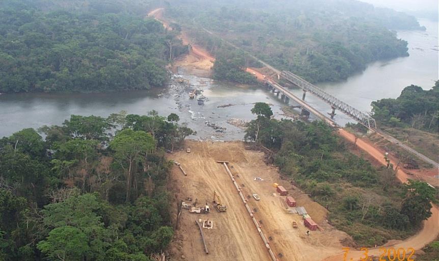
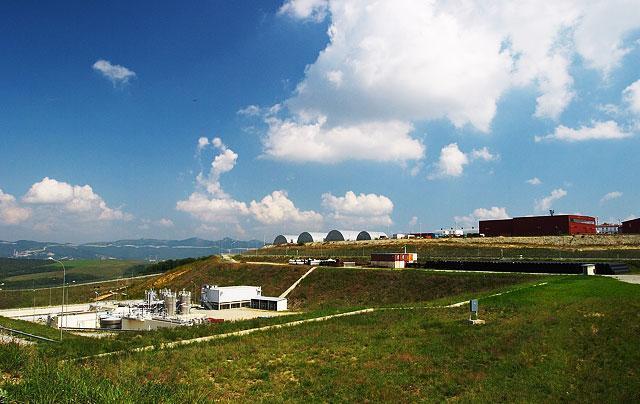

1 International Construction Consulting, LLC HDD Design, Calculations, and Cost Estimate Bow Tie to Industrial Park; Soyo, Angola
2 JOB No: NA PREPRD.BY: G Lamberson DATE: 16-Jan-18 SUBJECT: HDD General Calculations; Length & Angle & General Design Analysis; Cost Estimate Input Parameters Diameter (in.) = Wall Thickness (in.) = SMYS (psi) = 65,000 Type of Service = Gas Design Pressure = 1,440 Safety Factor = 0.72 Installation Temperature (degrees F) = Ground Temperature (degrees F) = Operating Temperature (degrees F) = Cover on Bottom (Ft) = Groundwater table head (feet) = Groundwater Table Elevation = Concrete Coated Pipe = No Concrete Coating Thickness (inches) = 0.00 Concrete Compressive Strength (PSI) = 0 Depth of Pipe relative to entry/exit at Lowest Point = Horizontal Length of Drill (Ft) = 1, Key Calculated Values D/t ratio = r o (in.) = 12 Results of this preliminary Technical Evaluation = for positive compressive forces, N = 0, i.e., no push or pull r i (in.) = 11.5 E (psi) = 3.05E+07 Young's modulus for steel (see calculation sheet ) I (in 4 ) = Moment of interia, = PI/4*(r 4 o - r 4 i ) R (in.) = 16,631 Radius of curvature in inches Deflection Angle = Radians/15 Feet Deflection Angle = Degress/15 Feet Deflection Angle = %/15 Feet M = (in-lb) = 4,670,570 M = EI/R A = (in 2 ) = Cross sect. area = PI*(D - t)*t W = (in 3 ) = (elastic) section modulus = PI/4*(D - t) 2 *t Calculated R.O.C. = 1,386 Feet (average of calculation methods) Top Bank at Entry of X-ing (Elev in Ft) = Ft Top Bank at Exit of X-ing (Elev in Ft) = Ft Bottom of X-ing (Elev in Ft) = Ft Entry Angle, Deg Deg Entry Elevation, ft Ft Minimum Depth Elevation, ft Ft Horizontal Depth, ft 1, Ft Exit Angle, Deg Deg Exit Elevation, ft 0.00 Ft Minimum Radius, ft 1, Ft Entry Point to PC Ft PC to PT Ft PT to PC 1, Ft PC to PT Ft PT to Exit Point Ft Length of Bore - Total Entry to Exit 1,923 Ft Maximum Pullback Force 224,841 Lbs Maximum Pullback Force 1,000 kn General Longitudinal Stresses (Sigma x ) N Sigma x (psi) = Sigma x + Sigma M x = N/A + M/W where Sigma x N = 0 Sigma x N = N/A This preliminary design has been evaluated and is deemed acceptable subject to a full design review. Length, Angles, & Misc Input and Calculations and Sigma x M = 21,536 Sigma x M = M/W 1/16/2018 HDD Stress Analysis & Results HDD Full Pipe & Installation Stress Analysis Rev 2.xlsm
3 JOB No: NA PREPRD.BY: G Lamberson DATE: 16-Jan-18 SUBJECT: HDD General Calculations; Length & Angle & General Design Analysis; Cost Estimate Critical Longitudinal Stresses (Sigma xcr ) when N acts alone, i.e., M = 0 and p = 0 Sigma xcr N (psi) = 63, Sigma x N = Sigma F *[1-.001*(D/t)-20)] N ~ axial for 20 < D/t < 100 when M acts alone, i.e., N = 0 and p = 0 Sigma xcr M (psi) = 73, Sigma x M = Sigma F *( *D/t) M ~ bending Given by: Sigma y = (p e - p i ) x D / (2 x t) where p e (psi) = 18.2 p e = external pressure = 0.052*W m *H W m (lbs) = 10 W m = weight of mud, lbs./gal. H (ft.) = H = feet of head (depth of burial) p i (psi) = 0 p i = internal pressure (assumed) Sigma y (psi) = conversion factor, converts #/gal to psi/ft. Critical Hoop Stress, (Sigma ycr ) when p acts alone, i.e., N = 0 and M = 0 Sigma ycr (psi) = 13, Sigma ycr = Sigma ye = E*(t / (D-t)) 2 ALPHA DETERMINATION: Nu xp is the permissible value of Sigma x /Sigma xcr, when Sigma y = 0 Nu yp is the permissible value of Sigma y /Sigma ycr, when Sigma x = 0 BEST CASE WORST CASE General Hoop Stress (Sigma y ) for Sigma ye < 2/3 Sigma F 2 /3 Sigma F (psi) = 43, OK Alpha = 1.20 Alpha = /(D/t)*Sigma y /Sigma ycr Permissible Usage Factors, (Nu xp and Nu yp ) Nu xp = 1.00 Nu yp = 0.98 Zone 1, loading Installation, loading Nu xp = 0.72 Nu yp = 0.62 Permissible Combination Of Sigma x and Sigma y (Sigma x /Nu xp *Sigma xcr ) alpha + (Sigma y /Nu yp *Sigma ycr ) < 1 BEST CASE WORST CASE OK OK Longitudinal Stress from Bending = 21,985 psi % SMYS = 33.8% Hoop Stress = 34,456 psi % SMYS = 53.0% Longitudinal Compressive Stress from Hoop Stress = 10,337 psi % SMYS = 15.9% Longitudinal Stress from Thermal Expansion = 1,981 psi % SMYS = 3.0% Net Longitudinal Compressive Stress = (9,667) psi % SMYS = 14.9% Maximum Shear Stress = 22,062 psi % SMYS = 33.9% Installation Design Results = OK Installation Stress Analysis Hoop stress limited by design factor from 49 CFR Part (72% for Class 1, 60% for Class 2) Shear stress limited to 45% of SMYS by of ASME/ANSI B31.4 1/16/2018 HDD Stress Analysis & Results HDD Full Pipe & Installation Stress Analysis Rev 2.xlsm
4 JOB No: NA PREPRD.BY: G Lamberson DATE: 16-Jan-18 SHEET: SUBJECT: Minimum Free Stress Radius of Curvature for Steel Pipe Pipe Parameters Minimum Radius of Curvature (Ft) for Steel Pipe Hoop Stress Case 1 Case 2 Case 3 Case 4 Case 5 Pipe OD WT ID MAOP SMYS F E T Pressure Pipeline Texas Gas Transmission Method Grade or Rating Temperature Method of JD Rules of Quantum McDermott MOP 195 & 195 & 192 at 72.% of Pipe psi Stress on Concrete Coating (psi) Hair Thumb Equation Equation only SMYS Pipe Method Best Case Worst Case Inches Inches Inches psig psi psig F Note 1 Note 1 Note 1 Note 2 Notes 2 & 3 Note 4 Note 5 API 5L X ,440 65, , ,560 2,400 ft 977 ft 1,538 ft 1,032 ft 982 ft 0 psi 0 psi Case 1: per JD Hair; Radius = f(od) Construction Temperature 90 F Case 2: per PipeLine Rules of Thumb Handbook Method, 2nd Ed; Radius = f ( OD,SMYS,F,ID,Es ) Minimum Ground Temperature 60 F Case 3: per Quantum Equation; Radius = f ( OD,SMYS ) Case 4: per McDermott Equation; Radius = f ( OD,SMYS,F,MAOP,WT,Es ) Concrete Parameters Case 5: per TGT Method; Radius = f ( OD,SMYS,F,ID,MAOP,WT,Es,Temp. ) Thickness 0.00 inches Concrete: Per TGT Method: Compressive Strength 0 psi Ccs (Best) T & C = f (Ec,(OD/2+WTc),Radius) Tensile Strength (*) 0 psi = 7 x (Ccs^½) (Worst) T = f(smys,f,ec,(od/2+wt),es,od) Modulus of Elasticity (*) 0.00E+00 psi = x (Ccs^½) Note 1: This case does not allow for stress due to internal pressure. Note 2: This case allows for stress due to internal pressure. Note 3: If MAOP/MOP = 0 then pipe is assumed to be casing. Note 4: The calculated quantity is the tension and compression (in psi). Best case assumes free relative motion between concrete inner surface and pipe outer surface. Note 5: The calculated quantity is the tension (in psi). Worst case assumes no relative motion between concrete inner surface and pipe outer surface. This case does not take radius of curvature into account as the interaction between the pipe and concrete is the worst case. 1/16/2018 Radius of Curvature HDD Full Pipe & Installation Stress Analysis Rev 2.xlsm
5 JOB No: NA PREPRD.BY: G Lamberson DATE: 28-Dec-17 SUBJECT: HDD General Calculations; Length & Angle & General Design Analysis; Cost Estimate GENERAL DATA PIPE WEIGHT DATA Pipe Diameter: Inches Pipe Weight in Air: Lb/ft Wall Thickness: Inches Pipe Interior Vol.: cu.ft/ft SMYS: 65,000 Psi Pipe Exterior Vol.: cu.ft/ft Young's Modulus: E+06 Psi Air Line Weight: 0 Lb/ft Total Pipe Length: 2,326 ft Air Line Diameter: 0 Inches Moment of Inertia: Inches^4 Air Line Ext. Vol.: cu.ft/ft Pipe Face Surface Area: Inches^2 Weight of Water: 0 Lb/ft Diameter/wall thickness ratio: 48 Displaced Mud Weight: Lb/ft Poisson's ratio for Steel: 0.3 Water density Mud Weight: Lb/cu.ft Enter 0 for no buoyancy control: 0.00 Lb/cu.ft Coefficient of Soil Friction.: 0.30 Effective Wt. of pipe: Lb/ft Fluid Drag Coefficient.: 0.05 Psi Note: positive value indicates downward force ANALYSIS OF LOADS FOR STRAIGHT SECTION PULLED DOWNSLOPE Measured Length: ft Axial Tension limited by RP2A-WSD Angle of Inclination: 12 degrees Comparison: 402 Psi < 58,500 = radians Longitudinal Bending limited by RP2A-WSD Comparison: 0 Psi < 42,940 Drag Forces from Mud: 5,487 Lb Friction from Soil: 5,485 Lb External Hoop Stress limited by RP2A-WSD Effective Weight of Pipe: (3,886) Lb Comparison: 374 Psi < 7,758 Combined Stresses, Tensile & Bending, limited by RP2A-WSD PULL LOAD AT POINT B Comparison: < 1 Tension on section: 14,857 Lb Cumulative Force exerted: 14,857 Lb Combined Stresses, Tensile, Bending & Hoop limited by RP2A-WSD Comparison: < 1 ANALYSIS OF LOADS FOR CURVILINEAR SECTION PULLED DOWNSLOPE Measured Length: ft Axial Tension limited by RP2A-WSD Change in Inclination Angle: 10 degrees Comparison: 1,308 Psi < 58,500 = radians Radius of Curvature: 1386 ft Longitudinal Bending limited by RP2A-WSD Center Displacement: ft Comparison: 21,985 Psi < 42,940 Assumed Average Tension: 4,191 Lb External Hoop Stress limited by RP2A-WSD Comparison: 687 Psi < 7,758 Normal Force: 32,076 Lb Drag Forces from Mud: 10,943 Lb Combined Stresses, Tensile & Bending, limited by RP2A-WSD Friction from Soil: 19,246 Lb Comparison: < 1 Effective Weight of Pipe: (3,249) Lb Combined Stresses, Tensile, Bending & Hoop limited by RP2A-WSD PULL LOAD AT POINT C Comparison: < 1 Tension on section: 33,438 Lb Average Tension: 31,576 Lb Cumulative Force exerted: 48,295 Lb ANALYSIS OF LOADS FOR HORIZONTAL STRAIGHT SECTION Measured Length: 1, ft Axial Tension limited by RP2A-WSD Angle of Inclination: 0 degrees Comparison: 5,170 Psi < 58,500 = 0 radians Longitudinal Bending limited by RP2A-WSD Comparison: 0 Psi < 42,940 Drag Forces from Mud: 70,502 Lb Friction from Soil: 72,052 Lb External Hoop Stress limited by RP2A-WSD Effective Weight of Pipe: 0 Lb Comparison: 730 Psi < 7,758 Combined Stresses, Tensile & Bending, limited by RP2A-WSD PULL LOAD AT POINT D Comparison: < 1 Tension on section: 142,553 Lb Cumulative Force exerted: 190,848 Lb Combined Stresses, Tensile, Bending & Hoop limited by RP2A-WSD Comparison: < 1 1/16/2018 Pulling Forces HDD Full Pipe & Installation Stress Analysis Rev 2.xlsm
6 JOB No: NA PREPRD.BY: G Lamberson DATE: 28-Dec-17 SUBJECT: HDD General Calculations; Length & Angle & General Design Analysis; Cost Estimate ANALYSIS OF LOADS FOR CURVILINEAR SECTION PULLED UPSLOPE Measured Length: ft Axial Tension limited by RP2A-WSD Change in Incl. Angle: 10 degrees Comparison: 5,810 Psi < 58,500 = radians Radius of Curvature: 1,386 ft Longitudinal Bending limited by RP2A-WSD Center Displacement: ft Comparison: 21,985 Psi < 42,940 Assumed Average Tension: 8,713 Lb External Hoop Stress limited by RP2A-WSD Comparison: 418 Psi < 7,758 Normal Force: 26,534 Lb Drag Forces from Mud: 10,943 Lb Combined Stresses, Tensile & Bending, limited by RP2A-WSD Friction from Soil: 15,921 Lb Comparison: < 1 Effective Weight of Pipe: (3,249) Lb Combined Stresses, Tensile, Bending & Hoop limited by RP2A-WSD PULL LOAD AT POINT E Comparison: < 1 Tension on section: 23,614 Lb Average Tension: 202,655 Lb Cumulative Force exerted: 214,462 Lb ANALYSIS OF LOADS FOR STRAIGHT SECTION PULLED UPSLOPE Length of Section: ft Axial Tension limited by RP2A-WSD Angle of Inclination: 10 degrees Comparison: 6,091 Psi < 58,500 = radians Longitudinal Bending limited by RP2A-WSD Comparison: 0 Psi < 42,940 Drag Forces from Mud: 7,335 Lb Friction from Soil: 7,382 Lb External Hoop Stress limited by RP2A-WSD Effective Weight of Pipe: (4,339) Lb Comparison: 0 Psi < 7,758 Combined Stresses, Tensile & Bending, limited by RP2A-WSD PULL LOAD AT POINT F Comparison: < 1 Tension on section: 10,378 Lb Cumulative Force exerted: 224,841 Lb Combined Stresses, Tensile, Bending & Hoop limited by RP2A-WSD Comparison: < 1 RESULTS Total Pulling Force: 224,841 Lb Stress Violations: 0 The pulling force analysis performed indicate the design is adequate. 1/16/2018 Pulling Forces HDD Full Pipe & Installation Stress Analysis Rev 2.xlsm
: 65,000 Maximum Allowable Operating Pressure (psi): 1,440 Poisson's ratio: 0.30 Young's Modulus: 3.")
7 JOB No: NA * PREPRD.BY: G Lamberson DATE: 16-Jan-18 SHEET: SUBJECT: HDD Installation Stress Analysis GENERAL DATA Pipe Diameter (inches): Wall Thickness (inches): SMYS (psi): 65,000 Maximum Allowable Operating Pressure (psi): 1,440 Poisson's ratio: 0.30 Young's Modulus: 3.0E+07 Radius of Curvature (feet): 1,386 Coefficient of Thermal Expansion (inches/inch/degree F): 6.5E-06 Installation Temperature (degrees F) = 90 Ground Temperature (degrees F) = 60 Operating Temperature (degrees F) = 80 Cover on Bottom (Ft) = 10 Groundwater table head (feet) = 10 HDD INSTALLATION STRESS ANALYSIS Longitudinal Stress from Bending = 21,985 psi % SMYS = 33.8% Hoop Stress = 34,456 psi Hoop stress limited by design % SMYS = 53.0% factor from 49 CFR Part (72% for Class 1, 60% for Class 2) Longitudinal Compressive Stress from Hoop Stress = 10,337 psi % SMYS = 15.9% Longitudinal Stress from Thermal Expansion = 1,981 psi % SMYS = 3.0% Net Longitudinal Compressive Stress = (9,667) psi % SMYS = 14.9% Maximum Shear Stress = 22,062 psi Shear stress limited to 45% of % SMYS = 33.9% SMYS by of ASME/ANSI B31.4 Installation Design Results = OK 1/16/2018 Installation Stress Analysis HDD Full Pipe & Installation Stress Analysis Rev 2.xlsm
8 JOB No: NA PREPRD.BY: G Lamberson 16-Jan-18 SUBJECT: HDD Operational Stress Analysis GENERAL DATA Pipe Diameter: Inches Wall Thickness: Inches SMYS: 65,000 psi Maximum Allowable Operating Pressure 1,440 psi Poisson's ratio: 0.3 Young's Modulus: 3.047E+07 Psi Radius of Curvature: 1,386 feet Coefficient of Thermal Expansion: 6.5E-06 inches/inch/ F Installation Temperature: F Operating Temperature: F Groundwater Table Depth Relative to Entry Point: feet Groundwater Table Elevation: feet Depth of Pipe relative to entry/exit at Lowest Point: -35 feet Groundwater Table Head: 25 feet Longitudinal Stress from Bending = 21,985 Allowable Stress per B31.4 = SMYS x F x E x T = Sa = 25,200 psi % SMYS = 33.8% % SMYS = 38.8% Longitudinal Stress from Thermal Expansion = 1,981 % SMYS = 3.0% DATA ANALYSIS PER METHOD OF JD HAIR Hoop Stress = 34,300 Hoop Stress limited by design factor from 49 CFR Part 192 or 195. % SMYS = 52.8% Net Longitudinal Compressive Stress = -9,714 Additive Longitudinal Stress Limit = 0.75 x Sa = 18,900 psi % SMYS = 14.9% % SMYS = 29.1% Maximum Shear Stress = 22,007 Shear stress limited to 45% of SMYS by of ASME/ANSI B31.4 % SMYS = 33.9% Based on the above calculations, the Operational Stress Analysis is Satisfactory 1/16/2018 Operational Stress Analysis HDD Full Pipe & Installation Stress Analysis Rev 2.xlsm
9 Modulus of Elasticity (psi x 10^6) Modulus of Elasticity (psi x 10^6) JOB No: NA PREPRD.BY: G Lamberson DATE: 16-Jan-18 SUBJECT: HDD - Modulus of Elasticity Calaculations Reference Temperature = F Modulus of Elasticity = ksi = E+06 psi The data below is calculated based on Perry's Chemical Engineer's Handbook, 6th Edition Carbon Steels with Carbon Material: Content: above 0.30 percent (0.3%) Modulus of Elasticity (ksi) at Temperature ( F) -325 F -200 F -100 F 70 F 200 F 300 F 400 F 500 F 600 F 700 F 800 F 900 F 1,000 F 1,100 F 1,200 F F -10 F 0 F 10 F 20 F 30 F 40 F 50 F 60 F 70 F 80 F 90 F 100 F 110 F 120 F Normal Temperature Range for Steel Pipe ( F) F -200 F -100 F 0 F 100 F 200 F 300 F 400 F 500 F 600 F 700 F 800 F 900 F 1,000 F 1,100 F 1,200 F Temperature ( F) 1/16/2018 Modulus of Elasticity HDD Full Pipe & Installation Stress Analysis Rev 2.xlsm
10 JOB No: NA PREPRD.BY: G Lamberson DATE: 16-Jan-18 SUBJECT: HDD Profile Details Horizontal Length Point of Entry ft. Point of Exit Grade 25.8 ft ft ft ft. Drill Data ft ft. Top Bank at Entry = 0.00 ft MSL 44.4 ft ft. Top Bank at Exit = 0.00 ft MSL 9.2 ft. 6.4 ft. Bottom of X-ing = ft MSL Cover on Bottom = 10.0 ft. 12 deg 10 deg Total Depth = 35.0 ft ft ft ft ft ft. Entry Side - Curve Data Exit Side - Curve Data Radius = ft Total Length of Pipe - Entry to Exit Radius = 982 ft Angle = 12 deg ft. Angle = 10 deg Length = ft Length = ft. Tangent = ft Tangent = ft. 1/16/2018 Profile HDD Full Pipe & Installation Stress Analysis Rev 2.xlsm
11 JOB No: CLIENT: PROJECT: SUBJECT: Pipe Diameter Pipe Wall Thickness Pipe Grade 65,000 Hours per Shift 12 Length of Drill 1,923 Feet Mobe/Demobe Costs $ 150,000 Each Type of Soil Gravel Pilot Hole Production Rate 55 Feet/Hr Drilling Mud Flow Rate 5 BPM Pilot Hole Duration 2.91 Shifts Circulation Loss 50% Pilot Hole Mud Qty 315 Sacks Pre-Ream Passes 3 Ea Pre-Ream Travel Speed 2.5 Feet/Min Pre-Ream Mud Flow Rate 10 BPM Pre-Ream Duration 1.07 Shifts Circulation loss 50% Pre-Reaming Mud Qty 692 Sacks Pull Back Travel Speed 8 Feet/Min Pull Back Mud Flow Rate 10 BPM Pull Back Duration 0.33 Shifts Circulation Loss 50% Pull Back Mud Quantity 72 Mud Cost $ Mobilization Time 30 Days Time Required to Drill 12 Days Total Time from Contract 42 Days NA DATE: 16-Jan-18 Sonangol Gas Natural PREPRD.BY: G Lamberson 24" Gas Pipeline from Bow Tie to Industrial Park-Soyo, Angola HDD Cost Estimate HDD Cost Estimate Activities Time Labor Equipment Misc Totals Mobilization $ 150,000 $ 150,000 Rig Up 4 $ 60,000 $ 100,000 $ 161,019 Pilot Hole 2.91 $ 43,707 $ 72,845 $ 117,570 Ream 1.07 $ 16,026 $ 26,710 $ 43,752 Pull Back 0.33 $ 5,008 $ 8,347 $ 14,370 Rig Down 4 $ 60,000 $ 100,000 $ 161,019 Demobilization $ 150,000 $ 150,000 Drilling Mud $ 144,725 $ 144,725 Sub Total Cost $ 942,456 Risk Premium 30% $ 282,737 Profit 20% $ 245,038 Total Cost $ 1,470,231 Cost/Ft $ /16/2018 Cost Estimate HDD Full Pipe & Installation Stress Analysis Rev 2.xlsm
External Pressure... Thermal Expansion in un-restrained pipeline... The critical (buckling) pressure is calculated as follows:
 pressure is calculated as follows:") External Pressure... The critical (buckling) pressure is calculated as follows: P C = E. t s ³ / 4 (1 - ν ha.ν ah ) R E ³ P C = Critical buckling pressure, kn/m² E = Hoop modulus in flexure, kn/m² t s
External Pressure... The critical (buckling) pressure is calculated as follows: P C = E. t s ³ / 4 (1 - ν ha.ν ah ) R E ³ P C = Critical buckling pressure, kn/m² E = Hoop modulus in flexure, kn/m² t s
Coating Requirements for Pipelines Installed by Horizontal Directional Drilling John D. Hair, P.E.*
 Coating Requirements for Pipelines Installed by Horizontal Directional Drilling John D. Hair, P.E.* *President, J. D. Hair & Associates, Inc., 2121 South Columbia Avenue, Suite 101, Tulsa, OK 74114-3502;
Visit Abqconsultants.com. This program Designs and Optimises RCC Chimney and Foundation. Written and programmed
 Prepared by : Date : Verified by : Date : Project : Ref Calculation Output Design of RCC Chimney :- 1) Dimensions of Chimney and Forces 200 Unit weight of Fire Brick Lining 19000 N/m3 100 Height of Fire
UNIVERSITY OF SASKATCHEWAN ME MECHANICS OF MATERIALS I FINAL EXAM DECEMBER 13, 2008 Professor A. Dolovich
 UNIVERSITY OF SASKATCHEWAN ME 313.3 MECHANICS OF MATERIALS I FINAL EXAM DECEMBER 13, 2008 Professor A. Dolovich A CLOSED BOOK EXAMINATION TIME: 3 HOURS For Marker s Use Only LAST NAME (printed): FIRST
Technical Note PP TN Engineering Considerations for Temperature Change
 Technical Note PP 814 - TN Engineering Considerations for Temperature Change www.performancepipe.com Like most materials, polyethylene is affected by temperature change. However, polyethylene s response
APRIL Conquering the FE & PE exams Formulas, Examples & Applications. Topics covered in this month s column:
 APRIL 2015 DR. Z s CORNER Conquering the FE & PE exams Formulas, Examples & Applications Topics covered in this month s column: PE Exam Specifications (Geotechnical) Transportation (Horizontal Curves)
This procedure covers the determination of the moment of inertia about the neutral axis.
 327 Sample Problems Problem 16.1 The moment of inertia about the neutral axis for the T-beam shown is most nearly (A) 36 in 4 (C) 236 in 4 (B) 136 in 4 (D) 736 in 4 This procedure covers the determination
Lab Exercise #5: Tension and Bending with Strain Gages
 Lab Exercise #5: Tension and Bending with Strain Gages Pre-lab assignment: Yes No Goals: 1. To evaluate tension and bending stress models and Hooke s Law. a. σ = Mc/I and σ = P/A 2. To determine material
ATTACHMENT L. HDD Reports
 ATTACHMET L HDD Reports Spire STL Pipeline LLC Implementation Plan August 2018 STL Pipeline 24-inch Cold Water Creek Crossing by Horizontal Directional Drilling HDD Design Report August 8, 2018 Prepared
Purpose of this Guide: To thoroughly prepare students for the exact types of problems that will be on Exam 3.
 ES230 STRENGTH OF MTERILS Exam 3 Study Guide Exam 3: Wednesday, March 8 th in-class Updated 3/3/17 Purpose of this Guide: To thoroughly prepare students for the exact types of problems that will be on
Stress Transformation Equations: u = +135 (Fig. a) s x = 80 MPa s y = 0 t xy = 45 MPa. we obtain, cos u + t xy sin 2u. s x = s x + s y.
 s x = 80 MPa s y = 0 t xy = 45 MPa. we obtain, cos u + t xy sin 2u. s x = s x + s y.") 014 Pearson Education, Inc., Upper Saddle River, NJ. All rights reserved. This material is protected under all copyright laws as they currently 9 7. Determine the normal stress and shear stress acting
014 Pearson Education, Inc., Upper Saddle River, NJ. All rights reserved. This material is protected under all copyright laws as they currently 9 7. Determine the normal stress and shear stress acting
2012 MECHANICS OF SOLIDS
 R10 SET - 1 II B.Tech II Semester, Regular Examinations, April 2012 MECHANICS OF SOLIDS (Com. to ME, AME, MM) Time: 3 hours Max. Marks: 75 Answer any FIVE Questions All Questions carry Equal Marks ~~~~~~~~~~~~~~~~~~~~~~
twenty one concrete construction: shear & deflection ARCHITECTURAL STRUCTURES: FORM, BEHAVIOR, AND DESIGN DR. ANNE NICHOLS SUMMER 2014 lecture
 ARCHITECTURAL STRUCTURES: FORM, BEHAVIOR, AND DESIGN DR. ANNE NICHOLS SUMMER 2014 lecture twenty one concrete construction: Copyright Kirk Martini shear & deflection Concrete Shear 1 Shear in Concrete
Guidelines for the Installation of SYGEF Pipes, Fittings and Valves
 Guidelines for the Installation of SYGEF Pipes, Fittings and Valves Calculation of Length Changes Length changes which occur in SYGEF can be calculated in the usual manner, taking into consideration the
PERIYAR CENTENARY POLYTECHNIC COLLEGE PERIYAR NAGAR - VALLAM THANJAVUR. DEPARTMENT OF MECHANICAL ENGINEERING QUESTION BANK
 PERIYAR CENTENARY POLYTECHNIC COLLEGE PERIYAR NAGAR - VALLAM - 613 403 - THANJAVUR. DEPARTMENT OF MECHANICAL ENGINEERING QUESTION BANK Sub : Strength of Materials Year / Sem: II / III Sub Code : MEB 310
Mechanics of Materials Primer
 Mechanics of Materials rimer Notation: A = area (net = with holes, bearing = in contact, etc...) b = total width of material at a horizontal section d = diameter of a hole D = symbol for diameter E = modulus
5. What is the moment of inertia about the x - x axis of the rectangular beam shown?
 1 of 5 Continuing Education Course #274 What Every Engineer Should Know About Structures Part D - Bending Strength Of Materials NOTE: The following question was revised on 15 August 2018 1. The moment
2. Rigid bar ABC supports a weight of W = 50 kn. Bar ABC is pinned at A and supported at B by rod (1). What is the axial force in rod (1)?
. What is the axial force in rod (1)?") IDE 110 S08 Test 1 Name: 1. Determine the internal axial forces in segments (1), (2) and (3). (a) N 1 = kn (b) N 2 = kn (c) N 3 = kn 2. Rigid bar ABC supports a weight of W = 50 kn. Bar ABC is pinned at
IDE 110 S08 Test 1 Name: 1. Determine the internal axial forces in segments (1), (2) and (3). (a) N 1 = kn (b) N 2 = kn (c) N 3 = kn 2. Rigid bar ABC supports a weight of W = 50 kn. Bar ABC is pinned at
CHAPTER 4: BENDING OF BEAMS
 (74) CHAPTER 4: BENDING OF BEAMS This chapter will be devoted to the analysis of prismatic members subjected to equal and opposite couples M and M' acting in the same longitudinal plane. Such members are
DESIGN AND DETAILING OF COUNTERFORT RETAINING WALL
 DESIGN AND DETAILING OF COUNTERFORT RETAINING WALL When the height of the retaining wall exceeds about 6 m, the thickness of the stem and heel slab works out to be sufficiently large and the design becomes
ALUMINUM STRUCTURAL PLATE HEADWALLS AASHTO LRFD BASIS OF DESIGN
 ALUMINUM STRUCTURAL PLATE EADWALLS AASTO LRFD BASIS OF DESIGN LANE ENTERPRISES, INC. www.lane-enterprises.com Required Backfill and Load Cases: ALUMINUM STRUCTURAL PLATE EADWALLS BASIS OF DESIGN Backfill
Solution: T, A1, A2, A3, L1, L2, L3, E1, E2, E3, P are known Five equations in five unknowns, F1, F2, F3, ua and va
 ME 323 Examination # 1 February 18, 2016 Name (Print) (Last) (First) Instructor PROBLEM #1 (20 points) A structure is constructed from members 1, 2 and 3, with these members made up of the same material
MECHANICS OF MATERIALS. Prepared by Engr. John Paul Timola
 MECHANICS OF MATERIALS Prepared by Engr. John Paul Timola Mechanics of materials branch of mechanics that studies the internal effects of stress and strain in a solid body. stress is associated with the
S E C T I O N 1 2 P R O D U C T S E L E C T I O N G U I D E - H E L I C A L S C R E W P I L E F O U N D A T I O N S
 1. P R O D U C T S E L E C T I O N G U I D E - H E L I C A L S C R E W P I L E F O U N D A T I O N S Helical foundation pile includes a lead and extension(s). The lead section is made of a central steel
EFFECTIVENESS OF HYDROFRACTURE PREDICTION FOR HDD DESIGN
 North American Society for Trenchless Technology (NASTT) No-Dig Show 2010 Chicago, Illinois May 2-7, 2010 Paper F-1-01 EFFECTIVENESS OF HYDROFRACTURE PREDICTION FOR HDD DESIGN Kimberlie Staheli, Ph.D.,
R13. II B. Tech I Semester Regular Examinations, Jan MECHANICS OF SOLIDS (Com. to ME, AME, AE, MTE) PART-A
 PART-A") SET - 1 II B. Tech I Semester Regular Examinations, Jan - 2015 MECHANICS OF SOLIDS (Com. to ME, AME, AE, MTE) Time: 3 hours Max. Marks: 70 Note: 1. Question Paper consists of two parts (Part-A and Part-B)
SET - 1 II B. Tech I Semester Regular Examinations, Jan - 2015 MECHANICS OF SOLIDS (Com. to ME, AME, AE, MTE) Time: 3 hours Max. Marks: 70 Note: 1. Question Paper consists of two parts (Part-A and Part-B)
Samantha Ramirez, MSE. Stress. The intensity of the internal force acting on a specific plane (area) passing through a point. F 2
 passing through a point. F 2") Samantha Ramirez, MSE Stress The intensity of the internal force acting on a specific plane (area) passing through a point. Δ ΔA Δ z Δ 1 2 ΔA Δ x Δ y ΔA is an infinitesimal size area with a uniform force
Samantha Ramirez, MSE Stress The intensity of the internal force acting on a specific plane (area) passing through a point. Δ ΔA Δ z Δ 1 2 ΔA Δ x Δ y ΔA is an infinitesimal size area with a uniform force
RETAINING WALL LOADS: Horizontal Equivalent Fluid Pressure = pcf. (Load Case = Soil)
") QuickWall 8.0 - RETAINING WALL ANALYSIS AND DESIGN ================================================================================ Job ID : Job Description : Designed By : ================================================================================
QuickWall 8.0 - RETAINING WALL ANALYSIS AND DESIGN ================================================================================ Job ID : Job Description : Designed By : ================================================================================
Please review the following statement: I certify that I have not given unauthorized aid nor have I received aid in the completion of this exam.
 Group Number: Please review the following statement: I certify that I have not given unauthorized aid nor have I received aid in the completion of this exam. Signature: INSTRUCTIONS Begin each problem
Horizontal Directional Drilling: An Approach to Design and Construction. Presenter: John Briand, PE Co-Author: Danielle Neamtu, PE
 Horizontal Directional Drilling: An Approach to Design and Construction Presenter: John Briand, PE Co-Author: Danielle Neamtu, PE Presentation Outline General HDD overview Conceptual-level evaluation Detailed
Strength of Material. Shear Strain. Dr. Attaullah Shah
 Strength of Material Shear Strain Dr. Attaullah Shah Shear Strain TRIAXIAL DEFORMATION Poisson's Ratio Relationship Between E, G, and ν BIAXIAL DEFORMATION Bulk Modulus of Elasticity or Modulus of Volume
BELT TENSIONS & HP RESULTS
 13 12 120' 3 SECTIONS @ 100' ARC 300' 7 SECTIONS @ 100' LOADING #1 1200 TPH 120' 204' ~ 1432.4' RADIUS 1696.1' CONVEYOR INPUT DATA BELT TENSIONS & HP RESULTS BELT WIDTH, inches = CAPACITY, tph = DENSITY,
EMA 3702 Mechanics & Materials Science (Mechanics of Materials) Chapter 2 Stress & Strain - Axial Loading
 Chapter 2 Stress & Strain - Axial Loading") MA 3702 Mechanics & Materials Science (Mechanics of Materials) Chapter 2 Stress & Strain - Axial Loading MA 3702 Mechanics & Materials Science Zhe Cheng (2018) 2 Stress & Strain - Axial Loading Statics
MA 3702 Mechanics & Materials Science (Mechanics of Materials) Chapter 2 Stress & Strain - Axial Loading MA 3702 Mechanics & Materials Science Zhe Cheng (2018) 2 Stress & Strain - Axial Loading Statics
Serviceability Deflection calculation
 Chp-6:Lecture Goals Serviceability Deflection calculation Deflection example Structural Design Profession is concerned with: Limit States Philosophy: Strength Limit State (safety-fracture, fatigue, overturning
N = Shear stress / Shear strain
 UNIT - I 1. What is meant by factor of safety? [A/M-15] It is the ratio between ultimate stress to the working stress. Factor of safety = Ultimate stress Permissible stress 2. Define Resilience. [A/M-15]
3 Hours/100 Marks Seat No.
 *17304* 17304 14115 3 Hours/100 Marks Seat No. Instructions : (1) All questions are compulsory. (2) Illustrate your answers with neat sketches wherever necessary. (3) Figures to the right indicate full
Part 1 is to be completed without notes, beam tables or a calculator. DO NOT turn Part 2 over until you have completed and turned in Part 1.
 NAME CM 3505 Fall 06 Test 2 Part 1 is to be completed without notes, beam tables or a calculator. Part 2 is to be completed after turning in Part 1. DO NOT turn Part 2 over until you have completed and
FINITE ELEMENT ANALYSIS OF ARKANSAS TEST SERIES PILE #2 USING OPENSEES (WITH LPILE COMPARISON)
") FINITE ELEMENT ANALYSIS OF ARKANSAS TEST SERIES PILE #2 USING OPENSEES (WITH LPILE COMPARISON) Ahmed Elgamal and Jinchi Lu October 07 Introduction In this study, we conduct a finite element simulation
FINITE ELEMENT ANALYSIS OF ARKANSAS TEST SERIES PILE #2 USING OPENSEES (WITH LPILE COMPARISON) Ahmed Elgamal and Jinchi Lu October 07 Introduction In this study, we conduct a finite element simulation
[5] Stress and Strain
![[5] Stress and Strain](/thumbs/95/123344550.jpg "[5] Stress and Strain") [5] Stress and Strain Page 1 of 34 [5] Stress and Strain [5.1] Internal Stress of Solids [5.2] Design of Simple Connections (will not be covered in class) [5.3] Deformation and Strain [5.4] Hooke s Law
[5] Stress and Strain Page 1 of 34 [5] Stress and Strain [5.1] Internal Stress of Solids [5.2] Design of Simple Connections (will not be covered in class) [5.3] Deformation and Strain [5.4] Hooke s Law
Solution: The moment of inertia for the cross-section is: ANS: ANS: Problem 15.6 The material of the beam in Problem
 Problem 15.4 The beam consists of material with modulus of elasticity E 14x10 6 psi and is subjected to couples M 150, 000 in lb at its ends. (a) What is the resulting radius of curvature of the neutral
Horizontal Directional Drill Feasibility Study. for the. Athabasca River Crossing
 Section 58 Application Horizontal Directional Drill Feasibility Study for the Design Report Project Athabasca River HDD Crossing Prepared for NOVA Gas Transmission Ltd. October 2014 December 2014 Page
NAME: Given Formulae: Law of Cosines: Law of Sines:
 NME: Given Formulae: Law of Cosines: EXM 3 PST PROBLEMS (LESSONS 21 TO 28) 100 points Thursday, November 16, 2017, 7pm to 9:30, Room 200 You are allowed to use a calculator and drawing equipment, only.
I certify that I have not given unauthorized aid nor have I received aid in the completion of this exam.
 NAME: ME 270 Fall 2012 Examination No. 3 - Makeup Please review the following statement: Group No.: I certify that I have not given unauthorized aid nor have I received aid in the completion of this exam.
IDE 110 Mechanics of Materials Spring 2006 Final Examination FOR GRADING ONLY
 Spring 2006 Final Examination STUDENT S NAME (please print) STUDENT S SIGNATURE STUDENT NUMBER IDE 110 CLASS SECTION INSTRUCTOR S NAME Do not turn this page until instructed to start. Write your name on
Lecture 15 Strain and stress in beams
 Spring, 2019 ME 323 Mechanics of Materials Lecture 15 Strain and stress in beams Reading assignment: 6.1 6.2 News: Instructor: Prof. Marcial Gonzalez Last modified: 1/6/19 9:42:38 PM Beam theory (@ ME
Properties of Sections
 ARCH 314 Structures I Test Primer Questions Dr.-Ing. Peter von Buelow Properties of Sections 1. Select all that apply to the characteristics of the Center of Gravity: A) 1. The point about which the body
five Mechanics of Materials 1 ARCHITECTURAL STRUCTURES: FORM, BEHAVIOR, AND DESIGN DR. ANNE NICHOLS SUMMER 2017 lecture
 ARCHITECTURAL STRUCTURES: FORM, BEHAVIOR, AND DESIGN DR. ANNE NICHOLS SUMMER 2017 lecture five mechanics www.carttalk.com of materials Mechanics of Materials 1 Mechanics of Materials MECHANICS MATERIALS
Rigid pavement design
 Rigid pavement design Lecture Notes in Transportation Systems Engineering Prof. Tom V. Mathew Contents 1 Overview 1 1.1 Modulus of sub-grade reaction.......................... 2 1.2 Relative stiffness
Entrance exam Master Course
 - 1 - Guidelines for completion of test: On each page, fill in your name and your application code Each question has four answers while only one answer is correct. o Marked correct answer means 4 points
GATE SOLUTIONS E N G I N E E R I N G
 GATE SOLUTIONS C I V I L E N G I N E E R I N G From (1987-018) Office : F-16, (Lower Basement), Katwaria Sarai, New Delhi-110016 Phone : 011-65064 Mobile : 81309090, 9711853908 E-mail: info@iesmasterpublications.com,
Symmetric Bending of Beams
 Symmetric Bending of Beams beam is any long structural member on which loads act perpendicular to the longitudinal axis. Learning objectives Understand the theory, its limitations and its applications
Name :. Roll No. :... Invigilator s Signature :.. CS/B.TECH (CE-NEW)/SEM-3/CE-301/ SOLID MECHANICS
/SEM-3/CE-301/ SOLID MECHANICS") Name :. Roll No. :..... Invigilator s Signature :.. 2011 SOLID MECHANICS Time Allotted : 3 Hours Full Marks : 70 The figures in the margin indicate full marks. Candidates are required to give their answers
Name :. Roll No. :..... Invigilator s Signature :.. 2011 SOLID MECHANICS Time Allotted : 3 Hours Full Marks : 70 The figures in the margin indicate full marks. Candidates are required to give their answers
ABS Consulting Project No
 SUPPORTING STRUCTURE DESIGN FOR BLAST RESISTANT WINDOWS CHILD DEVELOPMENT CENTER MOODY AFB, GA ABS Consulting Project No. 898 PREPARED FOR: ATLANTIC ENGINEERING SERVICE 6 ARLINGTON EXPRESSWAY BLDG. B,
Structural Calculations for Juliet balconies using BALCONY 2 System (Aerofoil) handrail. Our ref: JULB2NB Date of issue: March 2017
 handrail. Our ref: JULB2NB Date of issue: March 2017") Juliet balconies using BALCONY 2 System (Aerofoil) handrail PAGE 1 (ref: JULB2NB280317) Structural Calculations for Juliet balconies using BALCONY 2 System (Aerofoil) handrail Our ref: JULB2NB280317 Date
Juliet balconies using BALCONY 2 System (Aerofoil) handrail PAGE 1 (ref: JULB2NB280317) Structural Calculations for Juliet balconies using BALCONY 2 System (Aerofoil) handrail Our ref: JULB2NB280317 Date
Experimental Investigation of Soil-Pipe Friction Coefficients for Thermoplastic Pipes Installed in Selected Geological Materials
 North American Society for Trenchless Technology (NASTT) NASTT s 2014 No-Dig Show Orlando, Florida April 13-17, 2014 MM-T6-03 Experimental Investigation of Soil-Pipe Friction Coefficients for Thermoplastic
ASME BPVC VIII Example E E4.3.8 PTB
 ASME BPVC VIII-1 217 Example E4.3.7 - E4.3.8 PTB-4-213 Table of contents Comparison - Form for equations... 2 Example E4.3.7- Conical Transitions Without a Knuckle... 3 E4.3.7 Large End - Dished heads
PVP BUTANE STORAGE BULLET CALCULATION AND FEA VERIFICATION
 Proceedings of PVP2005 2005 ASME Pressure Vessels and Piping Division Conference July 17-21, 2005, Denver, Colorado USA PVP2005-71123 BUTANE STORAGE BULLET CALCULATION AND FEA VERIFICATION Zhanghai Wang
CE6306 STRENGTH OF MATERIALS TWO MARK QUESTIONS WITH ANSWERS ACADEMIC YEAR
 CE6306 STRENGTH OF MATERIALS TWO MARK QUESTIONS WITH ANSWERS ACADEMIC YEAR 2014-2015 UNIT - 1 STRESS, STRAIN AND DEFORMATION OF SOLIDS PART- A 1. Define tensile stress and tensile strain. The stress induced
Downloaded from Downloaded from / 1
 PURWANCHAL UNIVERSITY III SEMESTER FINAL EXAMINATION-2002 LEVEL : B. E. (Civil) SUBJECT: BEG256CI, Strength of Material Full Marks: 80 TIME: 03:00 hrs Pass marks: 32 Candidates are required to give their
Stress Analysis Lecture 3 ME 276 Spring Dr./ Ahmed Mohamed Nagib Elmekawy
 Stress Analysis Lecture 3 ME 276 Spring 2017-2018 Dr./ Ahmed Mohamed Nagib Elmekawy Axial Stress 2 Beam under the action of two tensile forces 3 Beam under the action of two tensile forces 4 Shear Stress
Problem d d d B C E D. 0.8d. Additional lecturebook examples 29 ME 323
 Problem 9.1 Two beam segments, AC and CD, are connected together at C by a frictionless pin. Segment CD is cantilevered from a rigid support at D, and segment AC has a roller support at A. a) Determine
[7] Torsion. [7.1] Torsion. [7.2] Statically Indeterminate Torsion. [7] Torsion Page 1 of 21
![[7] Torsion. [7.1] Torsion. [7.2] Statically Indeterminate Torsion. [7] Torsion Page 1 of 21](/thumbs/88/115835122.jpg "[7] Torsion. [7.1] Torsion. [7.2] Statically Indeterminate Torsion. [7] Torsion Page 1 of 21") [7] Torsion Page 1 of 21 [7] Torsion [7.1] Torsion [7.2] Statically Indeterminate Torsion [7] Torsion Page 2 of 21 [7.1] Torsion SHEAR STRAIN DUE TO TORSION 1) A shaft with a circular cross section is
[7] Torsion Page 1 of 21 [7] Torsion [7.1] Torsion [7.2] Statically Indeterminate Torsion [7] Torsion Page 2 of 21 [7.1] Torsion SHEAR STRAIN DUE TO TORSION 1) A shaft with a circular cross section is
Effect Of Material Nonlinearity On Submarine Pipeline During Laying
 Effect Of Material Nonlinearity On Submarine Pipeline During Laying Dr. Hakim Saeed Muhammed, Dr. Karim Radhi Obead, Anwar Sabah Abd Alameer Abstract: The main causes of nonlinearity are the large deformations
PLATE GIRDERS II. Load. Web plate Welds A Longitudinal elevation. Fig. 1 A typical Plate Girder
 16 PLATE GIRDERS II 1.0 INTRODUCTION This chapter describes the current practice for the design of plate girders adopting meaningful simplifications of the equations derived in the chapter on Plate Girders
KINGS COLLEGE OF ENGINEERING DEPARTMENT OF MECHANICAL ENGINEERING QUESTION BANK. Subject code/name: ME2254/STRENGTH OF MATERIALS Year/Sem:II / IV
 KINGS COLLEGE OF ENGINEERING DEPARTMENT OF MECHANICAL ENGINEERING QUESTION BANK Subject code/name: ME2254/STRENGTH OF MATERIALS Year/Sem:II / IV UNIT I STRESS, STRAIN DEFORMATION OF SOLIDS PART A (2 MARKS)
D : SOLID MECHANICS. Q. 1 Q. 9 carry one mark each. Q.1 Find the force (in kn) in the member BH of the truss shown.
 in the member BH of the truss shown.") D : SOLID MECHANICS Q. 1 Q. 9 carry one mark each. Q.1 Find the force (in kn) in the member BH of the truss shown. Q.2 Consider the forces of magnitude F acting on the sides of the regular hexagon having
D : SOLID MECHANICS Q. 1 Q. 9 carry one mark each. Q.1 Find the force (in kn) in the member BH of the truss shown. Q.2 Consider the forces of magnitude F acting on the sides of the regular hexagon having
STRESS STRAIN AND DEFORMATION OF SOLIDS, STATES OF STRESS
 1 UNIT I STRESS STRAIN AND DEFORMATION OF SOLIDS, STATES OF STRESS 1. Define: Stress When an external force acts on a body, it undergoes deformation. At the same time the body resists deformation. The
INTRODUCTION TO STRAIN
 SIMPLE STRAIN INTRODUCTION TO STRAIN In general terms, Strain is a geometric quantity that measures the deformation of a body. There are two types of strain: normal strain: characterizes dimensional changes,
Mechanics of Materials
 Mechanics of Materials Notation: a = acceleration = area (net = with holes, bearing = in contact, etc...) SD = allowable stress design d = diameter of a hole = calculus symbol for differentiation e = change
AXIAL FORCE IN PULLED-INTO-PLACE HDPE PIPES DURING AND AFTER INSTALLATION
 AXIAL FORCE IN PULLED-INTO-PLACE HDPE PIPES DURING AND AFTER INSTALLATION Abdul Ghafar Chehab 1 Ian D. Moore 2 Resumo Palavras-chaves: Abstract Work has been conducted to measure and calculate the axial
Job No. Sheet No. Rev. CONSULTING Engineering Calculation Sheet. Member Design - Steel Composite Beam XX 22/09/2016
 CONSULTING Engineering Calculation Sheet jxxx 1 Member Design - Steel Composite Beam XX Introduction Chd. 1 Grade 50 more common than Grade 43 because composite beam stiffness often 3 to 4 times non composite
Mechanical Engineering Ph.D. Preliminary Qualifying Examination Solid Mechanics February 25, 2002
 student personal identification (ID) number on each sheet. Do not write your name on any sheet. #1. A homogeneous, isotropic, linear elastic bar has rectangular cross sectional area A, modulus of elasticity
The science of elasticity
 The science of elasticity In 1676 Hooke realized that 1.Every kind of solid changes shape when a mechanical force acts on it. 2.It is this change of shape which enables the solid to supply the reaction
COLUMNS: BUCKLING (DIFFERENT ENDS)
") COLUMNS: BUCKLING (DIFFERENT ENDS) Buckling of Long Straight Columns Example 4 Slide No. 1 A simple pin-connected truss is loaded and supported as shown in Fig. 1. All members of the truss are WT10 43
COLUMNS: BUCKLING (DIFFERENT ENDS) Buckling of Long Straight Columns Example 4 Slide No. 1 A simple pin-connected truss is loaded and supported as shown in Fig. 1. All members of the truss are WT10 43
Dynamic Earth Pressure Problems and Retaining Walls. Behavior of Retaining Walls During Earthquakes. Soil Dynamics week # 12
 Dynamic Earth Pressure Problems and Retaining Walls 1/15 Behavior of Retaining Walls During Earthquakes - Permanent displacement = cc ' 2 2 due to one cycle of ground motion 2/15 Hence, questions are :
If the solution does not follow a logical thought process, it will be assumed in error.
 Please indicate your group number (If applicable) Circle Your Instructor s Name and Section: MWF 8:30-9:20 AM Prof. Kai Ming Li MWF 2:30-3:20 PM Prof. Fabio Semperlotti MWF 9:30-10:20 AM Prof. Jim Jones
CIVIL DEPARTMENT MECHANICS OF STRUCTURES- ASSIGNMENT NO 1. Brach: CE YEAR:
 MECHANICS OF STRUCTURES- ASSIGNMENT NO 1 SEMESTER: V 1) Find the least moment of Inertia about the centroidal axes X-X and Y-Y of an unequal angle section 125 mm 75 mm 10 mm as shown in figure 2) Determine
EMA 3702 Mechanics & Materials Science (Mechanics of Materials) Chapter 4 Pure Bending Homework Answers
 Chapter 4 Pure Bending Homework Answers") EA 3702 echanics & aterials Science (echanics of aterials) Chapter 4 Pure Bending Homework Answers 100 mm Homework 4.1 For pure bending moment of 5 kn m on hollow beam with uniform wall thickness of 10
EA 3702 echanics & aterials Science (echanics of aterials) Chapter 4 Pure Bending Homework Answers 100 mm Homework 4.1 For pure bending moment of 5 kn m on hollow beam with uniform wall thickness of 10
Design of a Balanced-Cantilever Bridge
 Design of a Balanced-Cantilever Bridge CL (Bridge is symmetric about CL) 0.8 L 0.2 L 0.6 L 0.2 L 0.8 L L = 80 ft Bridge Span = 2.6 L = 2.6 80 = 208 Bridge Width = 30 No. of girders = 6, Width of each girder
NORMAL STRESS. The simplest form of stress is normal stress/direct stress, which is the stress perpendicular to the surface on which it acts.
 NORMAL STRESS The simplest form of stress is normal stress/direct stress, which is the stress perpendicular to the surface on which it acts. σ = force/area = P/A where σ = the normal stress P = the centric
Task 1 - Material Testing of Bionax Pipe and Joints
 Task 1 - Material Testing of Bionax Pipe and Joints Submitted to: Jeff Phillips Western Regional Engineer IPEX Management, Inc. 20460 Duncan Way Langley, BC, Canada V3A 7A3 Ph: 604-534-8631 Fax: 604-534-7616
= 50 ksi. The maximum beam deflection Δ max is not = R B. = 30 kips. Notes for Strength of Materials, ET 200
 Notes for Strength of Materials, ET 00 Steel Six Easy Steps Steel beam design is about selecting the lightest steel beam that will support the load without exceeding the bending strength or shear strength
ACET 406 Mid-Term Exam B
 ACET 406 Mid-Term Exam B SUBJECT: ACET 406, INSTRUCTOR: Dr Antonis Michael, DATE: 24/11/09 INSTRUCTIONS You are required to answer all of the following questions within the specified time (90 minutes).you
The University of Melbourne Engineering Mechanics
 The University of Melbourne 436-291 Engineering Mechanics Tutorial Four Poisson s Ratio and Axial Loading Part A (Introductory) 1. (Problem 9-22 from Hibbeler - Statics and Mechanics of Materials) A short
SPECIFIC VERIFICATION Chapter 5
 As = 736624/(0.5*413.69) = 3562 mm 2 (ADAPT 3569 mm 2, B29, C6) Data Block 27 - Compressive Stresses The initial compressive strength, f ci, is the strength entered in the Material/Concrete input screen.
Calculating the Risk of Structural Failure
 Calculating the Risk of Structural Failure Presentation at Society of Reliability Engineers Meeting December 9, 2015 Bob Graber STARGroup Solutions, LLC robert.graber@stargroup.solutions Designing a Structure
PES Institute of Technology
 PES Institute of Technology Bangalore south campus, Bangalore-5460100 Department of Mechanical Engineering Faculty name : Madhu M Date: 29/06/2012 SEM : 3 rd A SEC Subject : MECHANICS OF MATERIALS Subject
8/11/14. Sheet 1. Colonial Flag 9390 So 300 West Sandy, UT
 8/11/14 Sheet 1 990 So 00 West Sandy, UT 84070 800 78-0500 Street Banner Sign Cloth Tension Calculations for Simple Span with Uniform Loads. Sign Cloth Span Sign Cloth Length Stretched Sign Cloth Sag Sign
BENCHMARK LINEAR FINITE ELEMENT ANALYSIS OF LATERALLY LOADED SINGLE PILE USING OPENSEES & COMPARISON WITH ANALYTICAL SOLUTION
 BENCHMARK LINEAR FINITE ELEMENT ANALYSIS OF LATERALLY LOADED SINGLE PILE USING OPENSEES & COMPARISON WITH ANALYTICAL SOLUTION Ahmed Elgamal and Jinchi Lu October 07 Introduction In this study: I) The response
Steel Cross Sections. Structural Steel Design
 Steel Cross Sections Structural Steel Design PROPERTIES OF SECTIONS Perhaps the most important properties of a beam are the depth and shape of its cross section. There are many to choose from, and there
SRI CHANDRASEKHARENDRA SARASWATHI VISWA MAHAVIDHYALAYA
 SRI CHANDRASEKHARENDRA SARASWATHI VISWA MAHAVIDHYALAYA (Declared as Deemed-to-be University under Section 3 of the UGC Act, 1956, Vide notification No.F.9.9/92-U-3 dated 26 th May 1993 of the Govt. of
Chapter 5 CENTRIC TENSION OR COMPRESSION ( AXIAL LOADING )
") Chapter 5 CENTRIC TENSION OR COMPRESSION ( AXIAL LOADING ) 5.1 DEFINITION A construction member is subjected to centric (axial) tension or compression if in any cross section the single distinct stress
Chapter 5 CENTRIC TENSION OR COMPRESSION ( AXIAL LOADING ) 5.1 DEFINITION A construction member is subjected to centric (axial) tension or compression if in any cross section the single distinct stress
A UNIQUE PIPELINE FAULT CROSSING DESIGN FOR A HIGHLY FOCUSED FAULT
 Proceedings of IPC 2004 International Pipeline Conference October 4-8, 2004 Calgary, Alberta, Canada IPC04-0102 A UNIQUE PIPELINE FAULT CROSSING DESIGN FOR A HIGHLY FOCUSED FAULT James D. Hart President
MAHALAKSHMI ENGINEERING COLLEGE
 MAHALAKSHMI ENGINEERING COLLEGE TIRUCHIRAALLI - 6113. QUESTION WITH ANSWERS DEARTMENT : CIVIL SEMESTER: V SUB.CODE/ NAME: CE 5 / Strength of Materials UNIT 3 COULMNS ART - A ( marks) 1. Define columns
2/23/ WIND PRESSURE FORMULA 2. PERCENT OF ALLOWABLE STRESS 3. FATIGUE DESIGN
 Original Title Presented by Northwest Signal copyright 2010 Designing & Building Structural Steel Products since 1976 Primary Users Traffic Signal Strain & Mast Arm Poles Cantilever & Bridge Sign Structures
Design of Reinforced Concrete Beam for Shear
 Lecture 06 Design of Reinforced Concrete Beam for Shear By: Civil Engineering Department UET Peshawar drqaisarali@uetpeshawar.edu.pk Topics Addressed Shear Stresses in Rectangular Beams Diagonal Tension
Lesson 25. Static Pile Load Testing, O-cell, and Statnamic. Reference Manual Chapter 18
 Lesson 25 Static Pile Load Testing, O-cell, and Statnamic Reference Manual Chapter 18 STATIC LOAD TESTING Most accurate method to determine static pile capacity Perform at design or construction stage
Solid Mechanics Homework Answers
 Name: Date: Solid Mechanics Homework nswers Please show all of your work, including which equations you are using, and circle your final answer. Be sure to include the units in your answers. 1. The yield
Calculations. Conceptual Cofferdam. Prepared for. LAN - Austin. August Briarpark Drive Suite 400 Houston, Texas 77042
 Calculations Conceptual Cofferdam Prepared for - Austin August 0 9 Briarpark Drive Suite 00 Houston, Texas 770 Contents Cofferdam Design Report. Cofferdam Conceptual Design Summary.... Analysis Drawings...
Experimental Investigation of Steel Pipe Pile to Concrete Cap Connections
 Brigham Young University BYU ScholarsArchive All Theses and Dissertations 211-4-19 Experimental Investigation of Steel Pipe Pile to Concrete Cap Connections Ryan S. Eastman Brigham Young University - Provo