SETTLING VELOCITY OF PARTICLES
|
|
|
- Bryan Lloyd
- 5 years ago
- Views:
Transcription
1 SETTLING VELOCITY OF PARTICLES
2 Equation for one-dimensional motion of particle through fluid Expression for acceleration of a particle settling in a fluid: m du dt = F e F b F D Where, F e = ma e acceleration in external field = a e =g in gravity settling, and ω 2 rin centrifugal field F b =Buoyant force = m ρ p ρ F D = Drag force, F D = C Dρu 2 A p 2 CD = Drag coefficient, Ap=Projected area F D always increases with velocity, and soon acceleration becomes 0. Terminal velocity is the constant velocity the particle attains when acceleration becomes 0.
3 DRAG COEFFICIENT & TERMINAL VELOCITY C D = F D A p ρu m du = F dt e F b F D = ma e m ρa ρ e C Dρu 2 A p p 2 du = a dt e 1 ρa ρ e C Dρu 2 A p p 2m a e 1 ρ ρ p = C Dρu 2 A p 2m u 2 = 2mg ρ p ρ C D ρρ p A p = 2 π 6 D p 3 ρ p g ρ p ρ C D ρρ p πdp 2 4 = 4D pg ρ p ρ 3C D ρ u = 4D pg ρ p ρ 3C D ρ
4

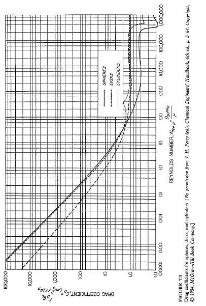
5 Drag Coefficients for spheres
6 Trial and error method for determination of terminal velocity u = 4D pg ρ p ρ 3C D ρ. (1) 1. Assume a value of u 2. Calculate Reynolds number of particle, N Re,p 3. N Re,p = D puρ μ D p = Diameter of particle, u = velocity of particle, ρ = density of fluid, μ= viscosity of fluid 4. Determine C D from chart of C D vs N Re,p 5. Calculate u from equation 1 6. Compare Calculated u with Assumed u, if error is not within limit restart from step 1 for second trial
7 Terminal velocity in Stokes Law range and Newtons law range u t = 4g ρ p ρ D p 3C D ρ Stokes Law range, particle Reynolds number less than 1.0 C D = 24, wheren N Re,p = D pu o ρ Re,p μ u t = gd p 2 ρ p ρ 18μ Newtons Law Range: 1000<N Re,p <200,000, C D = 0.44 u t = 1.75 gd p ρ p ρ ρ 7
8 u t = u t = 4g ρ p ρ D p 3C D ρ 4g ρ p ρ D p 3 24 = D p 2 g ρ p ρ u t ρ 18μ Dpuoρ μ u t = D p 2 g ρ p ρ 18μ
9 Determination of Range of settling Determine the value of K K = D p Stokes Law range K<2.6 gρ ρ p ρ μ 2 Newtons Law range K> Intermediate range K greater than 2.6 and less than 68.9
10 For Stokes Law range: Re p = D pu t ρ μ = D pρ μ Let K = D p ρg ρ p ρ μ 2 D p 2 g ρ p ρ 18μ 1/ K3 < 1, or K < 18 1/3 = 2.6 For Newtons law range = D p 3 ρg ρ p ρ 18μ 2 < 1 Re p = D pu t ρ μ 1.75K 1.5 = D pρ μ 1.75K 1.5 > 1000 K > gd p ρ p ρ ρ = 1.75D p 1.5 ρg ρ p ρ μ =
11 Estimate the terminal velocity of 80/100 mesh particles of limestone (density 2800kg/m3) settling in water at 30oC. Viscosity =0.801cP Determine K, to find range of settling, If K is not much larger than 2.6 Stokes law can be assumed and rechecked If K is not much less than 68.9 Newtons law can be assumed If K is in Intermediate range, trial and erro method to be followed
12 Hindered settling velocity u s = u t ε n where ε = porosity
13 Particles of sphalerite (sp. Gr. 4.00) are settling under the force of gravity in the carbon tetrachloride (CCl4) at 20oC(sp.gr ). The diameter of the sphalerite particles is 0.1 mm. The free settling terminal velocity is 0.015m/s. The volume fraction of sphalerite in carbon tetrachloride is 0.2. What is the settling velocity?
14 Solid Liquid Separation Settling Gravity and Centrifugal Reference McCabe Smith 14
15 GRAVITY SETTLING 15
16 16
17 Types of sedimentation tanks Circular Radial flow Conical Vertical flow Rectangular horizontal flow 17
18 Circular Radial Flow Gravity Thickener 18

19 DORR THICKENER 19
 3 = Clarified water overflow weir 4 = Primary sludge outlet")
20 Circular Radial Flow Gravity Thickener 1 = Raw wastewater inlet pipe 2 = Inlet stilling well (baffle) 3 = Clarified water overflow weir 4 = Primary sludge outlet pipe 20
21 After the removal of inorganic screenings and grit, the next step in wastewater treatment is the removal of the grosser suspended solids from the raw sewage. This is achieved via the process of primary settling or primary sedimentation. The wastewater flow is directed into one or more settling tanks, also known as primary clarifiers. Large mechanicallyraked circular tanks are generally used at the larger works,. The overall volume of the primary settling tank is designed to ensure the incoming wastewater will take a certain amount of time to flow completely through the structure. This is known as the retention time, and must be sufficiently long enough to allow suitable settling of the solids to take place, yet short enough to prevent the anaerobic breakdown of the settled solids from occurring (i.e. the settled sludge turning septic). The retention time can vary from 1 to 3 hours, depending on the plant loading and incoming wastewater characteristics. In a tank with a retention time of 2 hours, 50 to 70% of the suspended solids may be removed by settling and flotation (scum removal). Removal of these solids will also reduce the BOD by 30 to 35%. Of equal importance in the design of the primary settling tank is the surface loading rate. This will dictate the overall diameter of a circular settling tank. This is effectively the upward velocity of the incoming flow from the base of the tank to the top of the overflow weirs. Upflow velocities of around 1.0m per hour are generally desired. 21
22 VERTICAL SETTLING TANK Dortmund Type For small plants conical Dortmund-type settling tanks are preferred. Occasionally rectangular structures are used, with complex sludge and scum scraper mechanisms. Upward flow tank suited small treatment plants Steep floor slope, large lower hopper volume enable large sludge storage No need for scarping. Depth of hopper at least equal to the top dimension which is less than 6m 22
23 RECTANGULAR HORIZONTAL FLOW. Rectangular are for large primary settling tank Sensitive depth to width /length ratio Occasionally rectangular structures are used, with complex sludge and scum scraper mechanisms. Rectangular are for large primary settling tank Sensitive depth to width /length ratio 23

24 THICKENERS AND CLARIFIERS SETTLING OF FLOCCULATED PARTICLES Fine particles form agglomerates entrapping water within Flocculating agents strong electrolytes, polymeric - polyacrylamide Inexpensive water treatment materials lime alumina, sodium silicates, ferrous sulphate, ferric chloride etc. form loose agglomerates and removes fine particles. Batch Sedimentation test A= Clear liquid B = Uniform initial conc. C=Transition zone D= Settled solid 24

25 Time Height of clear liquid interface 0 Ho 25
26 gffd Plot settling rate curve from the following settling experimental data, and report (a)hindered settling velocity (b) settling in compression zone (c) critical composition. Time min Interface height m 26
27 SETTLING TANK DESIGN Ref: McCabe Smith There are two ways the solids can move to the bottom: 1. Under the influence of their settling velocity, downward 2. Due to the continuous removal of sludge at the bottom as underflow Feed Q i, C o overflow Q o Total downward flux of solids, Kg m 2 hr, consists of two parts the 1. Transport Flux, G t 2. Settling flux G s Underflow Q i, Q o, Q u =Flowrate of inlet, overflow and underflow C o, C u =Concentration of solids in inlet and underflow 27
28 Settling flux, Gs, also called the batch settling flux, this is due to the settlement of solids and as expected is a function of solids concentration and the settling velocity of particles. G s = dh dt dh i C i, C dt i = velocity and concentration at a layer i "i" in the thickener. It passes through a maxima, as at very low concentration settling rate is constant, and at high concentration the rate decreases rapidly. Transport flux, Gt,Fluxof solids carried by liquid, is independent of the solids settling in the thickener, whether the solids settle or not, there pumping of the sludge from the bottom of the tank. G t = uc i where, u= the velocity created by the underflow 28
29 SETTLING TANK AREA Total flux curve has a minimum value between the influent solids concentration (Co) and underflow solids concentration (Cu). This minimum flux is the maximum allowable solids loading for the thickener to work successfully. When flux is at minimum, we calculate for the maximum area required. If this limit is exceeded, the solids will overflow in the effluent. So the design of a thickener is thus reduced to the point of determining this flux. G = G t + G s = uc i + dh dt i C i As Solid introduced = solid removed QC o = Total flux x area QC o A = G t + G S min 29
30 KYNCH Method to obtain settling flux from one batch settling data Locate any time, ti Draw tangent at the point to cut y axis t Hi and x axis at ti Determine Ci: H 0 C 0 = H i C i and C i = H 0C 0 H i Determine settling velocity, dh dt Determine settling Flux : G s i = dh Plot Gsi vs Ci = H i i t i dt i C i [conc. at top of settling zone] t i t i H i C i dh dt i G s i 30
31 Following is the results of a settling experiment, with initial concentration of 60 g/l of calcium carbonate. Data is to be used to design a settling tank to handle 0.03m3/second of slurry, with an underflow velocity of 0.05m/h. Plot (a) Settling flux vs concentration, (b) transport flux vs concentration,(c) total flux vs concentration Determine minimum total flux, and cross sectional area of the tank. Time,min Height of interface, mm 31
32 CENTRIFUGAL SETTLING 32
33 Tubular Centrifuge Centrifugal liquid liquid separation Removal of solids from lubricating oil, ink, beverages etc. 10 to 15 cm dia 15,000rpm Solid/dirt accumulate inside the bow, and periodically removed 33
34 Disk Centrifuge Liquid liquid separation Removal of solids from lubricating oil, ink., beverages etc. Short wide bowl 20to 50cmdia Bowl filled with discs- cones of sheet metal set one above the other, with matching holes in the middle, which form the liquid passage Heavy liquid moves outwards and light liquid inwards. Soon Heavy Liquid touches lower side of a cone and separates out Shearing helps break emulsions Solid/dirt accumulate inside the bowl, and periodically removed 34
35 Nozzle discharge Centrifuge Modified disk centrifuge 3 mm dia holes at the periphery Dilute slurry leaves through hole Alternatively the holes are plugged most of the time and occasionally opened and thick slurry removed. 35
36 HELICAL CONVEYER CENTRIFUGE Bowl diameter 10cm to 140 cm Solid removal rate 1 to 2 tons/h to 50tons/h May not clarify 100% may require subsequent clarifier Separate free particles from water, like crystals, dewater etc 36
37 r 2 = radius of the bowl r 1 = radius at liquid surface b =depth of bowl D p = particle size r A = position of particle at inlet r B = position of particle at outlet Sedimenting Centrifuge u t = ω2 rd 2 p ρ p ρ 18μ Since u t = dr dt Time required for a particle of size Dp to travel from radius ra to rb. 0 t T dt = ra r B 18μ ω 2 ρ p ρ D p 2 t T = 18μ ω 2 ρ p ρ D p 2 ln r B r A Residence time t T = Volume q = πb r 2 2 r 1 2 q = πbω2 ρ p ρ D p 2 18μ q dr r r 2 2 r 1 2 ln r B r A 37
38 CUT DIAMETER Cut point diameter particles that travels half the distance between r 2 and r 1 in the available time For the particles to be removed r A = r 1+r 2 2 r B = r 2 q = πbω2 ρ p ρ D p 2 18μ r 2 2 r 1 2 ln r B r A and q c = πbω2 ρ p ρ D pc 2 18μ r 2 2 r 1 2 ln 2r 2 r1+r2 38
39 Special case: very thin liquid layer r 1 r 2 u t = ω2 r 2 D p 2 ρ p ρ 18μ Let the thickness = s If Cut dia is D pc the particles have to travel a distance s/2 u t = s 2t T Residence time t T = V q c q c = V t T = 2Vu t s = 2Vω2 r 2 D p 2 ρ p ρ 18μs 39
40 Sigma Value: a parameter for scale up q c = 2Vω2 r 2 D 2 p ρ p ρ 18μs Let re and se be average value of radius and liquid layer thickness q c = 2Vω2 r e D 2 p ρ p ρ 18μs e = 2Vω2 r e gs e D p 2 g ρ p ρ 18μ = 2 U G Sigma value, = Vω2 r e gs e, is a characteristics of centrifuge. It is the cross sectional area of a gravity settling tank of the same separation capacity as the centrifuge. 40
41 41
42 What is the capacity in cubic meters per hour of a clarifying centrifuge operating under the following conditions? Diameter of bowl, 600mm Thickness of liquid layer, 75mm Sp.gr of liquid 1.2 sp.gr of solid 1.6 Depth of bow 400 mm Viscosity of liquid 2 cp Speed, 1,200rpm Cut size 30μm 42
LIQUID/SOLID SEPARATIONS Filtration, Sedimentation, Centrifuges Ron Zevenhoven ÅA Thermal and Flow Engineering
 7 ÅA 44514 / 010 / 016 Fluid and Particulate systems 44514 /016 LIQUID/SOLID SEPARATIONS Filtration, Sedimentation, Centrifuges Ron Zevenhoven ÅA Thermal and Flow Engineering ron.zevenhoven@abo.fi 7.1
SEDIMENTATION INTRODUCTION
 SEDIMENTATION INTRODUCTION Sedimentation is removal of particulate materials suspended in water by quiescent settling due to gravity Commonly used unit operation in water and wastewater treatment plants
Centrifugation. Tubular Bowl Centrifuge. Disc Bowl Centrifuge
 CENTRIFUGATION Centrifugation Centrifugation involves separation of liquids and particles based on density. Centrifugation can be used to separate cells from a culture liquid, cell debris from a broth,
Module 15 : Grit Chamber. Lecture 19 : Grit Chamber
 Module 15 : Grit Chamber Lecture 19 : Grit Chamber 15. GRIT CHAMBER Grit chamber is the second unit operation used in primary treatment of wastewater and it is intended to remove suspended inorganic particles
15. GRIT CHAMBER 15.1 Horizontal Velocity in Flow Though Grit Chamber
 15. GRIT CHAMBER Grit chamber is the second unit operation used in primary treatment of wastewater and it is intended to remove suspended inorganic particles such as sandy and gritty matter from the wastewater.
Module 15 : Grit Chamber. Lecture 19 : Grit Chamber
 1 P age Module 15 : Grit Chamber Lecture 19 : Grit Chamber 2 P age Grit chamber is the second unit operation used in primary treatment of wastewater and it is intended to remove suspended inorganic particles
Chapter 6: Solid-Liquid Separation in WWTPs. Raúl Muñoz Pedro García Encina
 Chapter 6: Solid-Liquid Separation in WWTPs Raúl Muñoz Pedro García Encina 1 Introduction to Solid-Liquid Separation 2 Introduction: Separation Methods Solid/liquid separation technologies Ensure good
Lecture-6 Motion of a Particle Through Fluid (One dimensional Flow)
") Lecture-6 Motion of a Particle Through Fluid (One dimensional Flow) 1 Equation of Motion of a spherical Particle (one dimensional Flow) On Board 2 Terminal Velocity Particle reaches a maximum velocity
Lecture-6 Motion of a Particle Through Fluid (One dimensional Flow) 1 Equation of Motion of a spherical Particle (one dimensional Flow) On Board 2 Terminal Velocity Particle reaches a maximum velocity
PRIMARY TREATMENT NATURE
 PRIMARY TREATMENT NATURE Physical and chemical processes. Physical: sedimentation based in density differences Chemical: coagulation and flocculation, ph adjustment, precipitation (formation of insoluble
Separation Processes: Sedimentation Separations
 Separation Processes: Sedimentation Separations ChE 4M3 Kevin Dunn, 2014 kevin.dunn@mcmaster.ca http://learnche.mcmaster.ca/4m3 Overall revision number: 300 (September 2014) 1 Copyright, sharing, and attribution
1 Turbidity = NTU 2pH = 3 Alkalinity = mg/l as CaCO 3 4 Temperature = 5 Fe mg/l 6 Mn mg/l 7 Total Hardness mg/l as CaCO 3
 DESIGN CALIFIER TANK (SLUDGE BLANKET CLARIFIER TYPE : VERTICAL SLUDGE BLANKET) 1. Flow Rate Q = 150 m /hr. Raw Water Quality input 1 Turbidity = NTU ph = Alkalinity = mg/l as CaCO Temperature = 5 Fe mg/l
INDIAN INSTITUTE OF TECHNOLOGY ROORKEE NPTEL NPTEL ONLINE CERTIFICATION COURSE. Unit Operations of Particulate Matter
 INDIAN INSTITUTE OF TECHNOLOGY ROORKEE NPTEL NPTEL ONLINE CERTIFICATION COURSE Unit Operations of Particulate Matter Lec-04 Centrifugal Sedimentation and Equipment (Part - 1) Dr. Shabina Khanam Department
THEORY: SETTLING PROCESSES
 INTRODUCTION MANY METHODS OF MECHANICAL SEPARATION ARE BASED ON THE MOVEMENT OF THE SOLID PARTICLES OR LIQUID DROPS THROUGH A FLUID. IN THIS TOPIC WE ARE FOCUSING ON SOME SITUATIONS OF THE PARTICLES DELIBERATELY
1 Turbidity = NTU 2 ph = Alkalinity = 34 mg/l as CaCO 3 4 Temperature = 5 Fe = 2 mg/l 6 Mn = mg/l 7 Total Hardness = 50mg/l as CaCO 3
 DESIGN CALIFIER TANK (SLUDGE BLANKET CLARIFIER TYPE : SLUDGE RECIRCULATION) 1. Flow Rate Q 150 m 3 /hr. Raw Water Quality input 1 Turbidity NTU ph 8.3 3 Alkalinity 3 mg/l as CaCO 3 Temperature 5 Fe mg/l
THINK FLUID DYNAMIX CFD Simulation of Clarifiers. THINK Fluid Dynamix
 THINK FLUID DYNAMIX CFD Simulation of Clarifiers Provided by: THINK Fluid Dynamix Am Pestalozziring 21 D-91058 Erlangen (Germany) Tel. +49 (0)9131 69098-00 http://www.think-fd.com CFD ENGINEERING & CONSULTING
Sedimentation. Several factors affect the separation of settleable solids from water. Some of the more common types of factors to consider are:
 Sedimentation Sedimentation, or clarification, is the process of letting suspended material settle by gravity. Suspended material may be particles, such as clay or silts, originally present in the source
Effect of Particle Drag on Performance of a Conical Base Classifier
 Effect of Particle Drag on Performance of a Conical Base Classifier 1 Bharath N, 2 Swapnil Urankar, 3 Venkatesh L K, 4 Aditya Ramkumar, 5 Rohit Dua Applied Innovation EnSci A Weir Group Company Bangalore,
L-10 SEDIMENTATION PART-I
 L-10 SEDIMENTATION PART-I Environmental Engineering-I CONTETS Types of settling, Theory of settling L-12 PART -II CONTENTS Theory of settling (Continued ) ZONES IN SETTLING TANK A c/s
Chapter XII. Special Topics Report Centrifuge Settling & Filtration Theory
 Chapter XII. Special Topics Report Centrifuge Settling & Filtration Theory I. Introduction Settling and filtration are two very important operations for separating solids from a liquid solution. With proper
INDBOND 3000 Dry Strength Resin for Paper
 INDBOND 3000 Dry Strength Resin for Paper INDBOND 3000 Dry Strength Resins are specially formulated polymers designed for better paper making and to improve strength characteristics like burst factor,
CHAPTER 10 MECHANICAL SEPARATIONS
 CHAPTER 10 MECHANICAL SEPARATIONS Mechanical separations can be divided into four groups - sedimentation, centrifugal separation, filtration and sieving. In sedimentation, two immiscible liquids, or a
V/ t = 0 p/ t = 0 ρ/ t = 0. V/ s = 0 p/ s = 0 ρ/ s = 0
 UNIT III FLOW THROUGH PIPES 1. List the types of fluid flow. Steady and unsteady flow Uniform and non-uniform flow Laminar and Turbulent flow Compressible and incompressible flow Rotational and ir-rotational
Discrete particle settling. Flocculent settling. Compression
 An introduction to sedimentation theory in wastewater treatment Bengt Carlsson Systems and Control Group Uppsala University Nov 96, rev Okt 98 Abstract This material is made for the course \Wastewater
CEE 370 Environmental Engineering Principles
 Updated: 29 September 2015 Print version EE 370 Environmental Engineering Principles Lecture #9 Material Balances I Reading: Mihelcic & Zimmerman, hapter 4 Davis & Masten, hapter 4 David Reckhow EE 370
See us (live!) at Pittcon Booth 1039
 at Pittcon Booth 1039") See us (live!) at Pittcon Booth 1039 Meeting Green Goals with Zeta Potential and the SZ100 will start soon. Jeffrey Bodycomb, Ph.D. HORIBA Scientific www.horiba.com/us/particle Meeting Green Goals with
See us (live!) at Pittcon Booth 1039 Meeting Green Goals with Zeta Potential and the SZ100 will start soon. Jeffrey Bodycomb, Ph.D. HORIBA Scientific www.horiba.com/us/particle Meeting Green Goals with
The Islamic University of Gaza- Civil Engineering Department Sanitary Engineering- ECIV 4325 L7. Physical Wastewater Treatment
 The Islamic University of Gaza- Civil Engineering Department Sanitary Engineering- ECIV 4325 L7. Physical Wastewater Treatment Based on Dr. Fahid Rabah lecture notes Why do we need to treat wastewater?
CREAM SEPARATION. Centrifugation. Chapter 8
 College of Agricultural Engineering and Technology Dept. of Agricultural Processing and Food Engineering Course : Dairy and Food Engineering Chapter 8 CREAM SEPARATION (Cream separation, Centrifugation,
BAE 820 Physical Principles of Environmental Systems
 BAE 820 Physical Principles of Environmental Systems Stokes' law and Reynold number Dr. Zifei Liu The motion of a particle in a fluid environment, such as air or water m dv =F(t) - F dt d - 1 4 2 3 πr3
Module 9: Packed beds Lecture 29: Drag, particles settling. Flow through a packed bed of solids. Drag. Criteria of settling.
 Flow through a packed bed of solids Drag Criteria of settling Hindred settling file:///d /Web%20Course/Dr.%20Nishith%20Verma/local%20server/fluid_mechanics/lecture29/29_1.htm[5/9/2012 3:38:37 PM] Flow
Chapter 6 Pneumatic Transport
 Chapter 6 Pneumatic Transport 6.1 Pneumatic Transport Use of a gas to transport a particulate solid through pipeline Powder Rotary valve Blower Three major variables for pneumatic conveying - solid mass
INTRODUCTION AND OVERVIEW
 INTRODUCTION AND OVERVIEW All natural waters and wastewaters contain particles with a wide range of physical and chemical characteristics. These particles can decrease the clarity of the water, and they
ENERGY TRANSFER BETWEEN FLUID AND ROTOR. Dr. Ir. Harinaldi, M.Eng Mechanical Engineering Department Faculty of Engineering University of Indonesia
 ENERGY TRANSFER BETWEEN FLUID AND ROTOR Dr. Ir. Harinaldi, M.Eng Mechanical Engineering Department Faculty of Engineering University of Indonesia Basic Laws and Equations Continuity Equation m m ρ mass
Separation Processes
 Separation Processes ChE 4M3 Kevin Dunn, 2012 kevin.dunn@mcmaster.ca http://learnche.mcmaster.ca/4m3 Overall revision number: 97 (October 2012) 1 Copyright, sharing, and attribution notice This work is
Chapter 6 Pneumatic Transport and Standpipes
 Chapter 6 Pneumatic Transport and Standpipes 6.1 Pneumatic Transport Use of a gas to transport a particulate solid through pipeline Powder Rotary valve Blower Three major variables for pneumatic conveying
2 Navier-Stokes Equations
 1 Integral analysis 1. Water enters a pipe bend horizontally with a uniform velocity, u 1 = 5 m/s. The pipe is bended at 90 so that the water leaves it vertically downwards. The input diameter d 1 = 0.1
Tutorial 10. Boundary layer theory
 Tutorial 10 Boundary layer theory 1. If the velocity distribution law in a laminar boundary layer over a flat plate is assumes to be of the form, determine the velocity distribution law. At y = 0, u= 0
L-17 Coagulation and Flocculation Part-I. Environmental Engineering-I
 L-17 Coagulation and Flocculation Part-I Environmental Engineering-I Content Part-I Coagulation, Types of Coagulant, Part-II dosing, rapid mixing, Flocculation-design parameters. Purpose The primary purpose
Week 7 Assignment 7. The due date for submitting this assignment has passed NPTEL - Privacy & Terms - Honor Code - FAQs - Funded by
 X reviewer2@nptel.iitm.ac.in Courses» Introduction to Mineral Processing Unit 8 - Announcements Course Ask a Question Progress Mentor Course outline How to access the portal Assignment 7 The due date for
8.6 Drag Forces in Fluids
 86 Drag Forces in Fluids When a solid object moves through a fluid it will experience a resistive force, called the drag force, opposing its motion The fluid may be a liquid or a gas This force is a very
Water Pollution Control: Physical Methods. AWPPCE RPI Fall 2013
 Water Pollution Control: Physical Methods AWPPCE RPI Fall 2013 Water Pollution Control Processes Water and Waste Water Treatment are usually carried out in specially designed vessels (reactors) under controlled
Mechanical Engineering Programme of Study
 Mechanical Engineering Programme of Study Fluid Mechanics Instructor: Marios M. Fyrillas Email: eng.fm@fit.ac.cy SOLVED EXAMPLES ON VISCOUS FLOW 1. Consider steady, laminar flow between two fixed parallel
Studies on the Performance of Air Cyclone Separator for Removal of Particulate Matter
 Proceedings of the International Seminar on Mineral Processing Technology - 2006, Chennai, India. pp. 352-357. Studies on the Performance of Air Cyclone Separator for Removal of Particulate Matter Ch.
C C C C 2 C 2 C 2 C + u + v + (w + w P ) = D t x y z X. (1a) y 2 + D Z. z 2
 = D t x y z X. (1a) y 2 + D Z. z 2") This chapter provides an introduction to the transport of particles that are either more dense (e.g. mineral sediment) or less dense (e.g. bubbles) than the fluid. A method of estimating the settling velocity
This chapter provides an introduction to the transport of particles that are either more dense (e.g. mineral sediment) or less dense (e.g. bubbles) than the fluid. A method of estimating the settling velocity
Development of a dynamic process model for the mechanical fluid separation in decanter centrifuges
 Development of a dynamic process model for the mechanical fluid separation in decanter centrifuges Marco Gleiß a, Hermann Nirschl a a Institute for Mechanical Process Engineering and Mechanics, Karlsruhe
Sedimentation. Treatment Processes. Sedimentation. Sedimentation. Sedimentation. Sedimentation. CIVL 1112 Water Treatment - Sedimentation 1/7
 CIVL 111 Water Treatment - 1/7 Treatment Processes is te donards movement of an object relative to its surrounding medium, due to te force of gravity. Screening Aeration Preclorination locculation Coagulation
industrial wastewater applications of coagulants and flocculants
 Water Technologies & Solutions technical paper industrial wastewater applications of coagulants and flocculants Author: Peter E. Norman, SUEZ Water Technologies & Solutions, Trevose, PA Presented at WEFTEC2018
AP Physics Laboratory #6.1: Analyzing Terminal Velocity Using an Interesting Version of Atwood s Machine
 AP Physics Laboratory #6.1: Analyzing Terminal Velocity Using an Interesting Version of Atwood s Machine Name: Date: Lab Partners: PURPOSE The purpose of this Laboratory is to study a system as it approaches
ECOTAN SERIES. Natural Based Coagulants
 ECOTAN SERIES Natural Based Coagulants Results and examples Fruits, Textile, Slaughterhouses. Dairy, Species, PWTP. Ice Cream, Paper & Cardboard, WWTP. In general, ECOTAN series are efficient on both sedimentation
What do I need to know to pass an Advanced Industrial Wastewater License Test?
 What do I need to know to pass an Advanced Industrial Wastewater License Test? [Activated sludge, metals finishing, sedimentation/clarification with chemicals, DAF] All of the Basic Industrial Wastewater
Modelling of dispersed, multicomponent, multiphase flows in resource industries. Section 3: Examples of analyses conducted for Newtonian fluids
 Modelling of dispersed, multicomponent, multiphase flows in resource industries Section 3: Examples of analyses conducted for Newtonian fluids Globex Julmester 017 Lecture # 04 July 017 Agenda Lecture
1 Millimeter. 1 Micron. 1 Nanometer. 1 Angstrom ELECTRON SEPARATION PROCESS COMMON MATERIALS PARTICLE SIZE LOG SCALE MAGNETIC RANGE SPECTRUM
 HANDOUT 3. Millimeter Micron Nanometer Angstrom 00 APPROX. MOLEC. WT. 0 000 00 0 000 00 0 8 7 6 5 4 3 2 0 Radio waves Infrared Ultraviolet Visible X-rays MACRO MICRO MOLECULAR IONIC MOLECULE MACRO 200k
These subclasses are to be used according to the following general rules:
 CPC - B03D - 2017.08 B03D FLOTATION; DIFFERENTIAL SEDIMENTATION (sedimentation in general B01D 21/00; in combination with other separation of solids B03B; sink-float separation B03B 5/28; detergents, soaps
S.E. (Mech.) (First Sem.) EXAMINATION, (Common to Mech/Sandwich) FLUID MECHANICS (2008 PATTERN) Time : Three Hours Maximum Marks : 100
 (First Sem.) EXAMINATION, (Common to Mech/Sandwich) FLUID MECHANICS (2008 PATTERN) Time : Three Hours Maximum Marks : 100") Total No. of Questions 12] [Total No. of Printed Pages 8 Seat No. [4262]-113 S.E. (Mech.) (First Sem.) EXAMINATION, 2012 (Common to Mech/Sandwich) FLUID MECHANICS (2008 PATTERN) Time : Three Hours Maximum
Total No. of Questions 12] [Total No. of Printed Pages 8 Seat No. [4262]-113 S.E. (Mech.) (First Sem.) EXAMINATION, 2012 (Common to Mech/Sandwich) FLUID MECHANICS (2008 PATTERN) Time : Three Hours Maximum
Fluid Mechanics. du dy
 FLUID MECHANICS Technical English - I 1 th week Fluid Mechanics FLUID STATICS FLUID DYNAMICS Fluid Statics or Hydrostatics is the study of fluids at rest. The main equation required for this is Newton's
PROPERTIES OF FLUIDS
 Unit - I Chapter - PROPERTIES OF FLUIDS Solutions of Examples for Practice Example.9 : Given data : u = y y, = 8 Poise = 0.8 Pa-s To find : Shear stress. Step - : Calculate the shear stress at various
FLUID MECHANICS D203 SAE SOLUTIONS TUTORIAL 2 APPLICATIONS OF BERNOULLI SELF ASSESSMENT EXERCISE 1
 FLUID MECHANICS D203 SAE SOLUTIONS TUTORIAL 2 APPLICATIONS OF BERNOULLI SELF ASSESSMENT EXERCISE 1 1. A pipe 100 mm bore diameter carries oil of density 900 kg/m3 at a rate of 4 kg/s. The pipe reduces
150A Review Session 2/13/2014 Fluid Statics. Pressure acts in all directions, normal to the surrounding surfaces
 Fluid Statics Pressure acts in all directions, normal to the surrounding surfaces or Whenever a pressure difference is the driving force, use gauge pressure o Bernoulli equation o Momentum balance with
Chapter (4) Motion of Fluid Particles and Streams
 Motion of Fluid Particles and Streams") Chapter (4) Motion of Fluid Particles and Streams Read all Theoretical subjects from (slides Dr.K.AlASTAL) Patterns of Flow Reynolds Number (R e ): A dimensionless number used to identify the type of flow.
Chapter (4) Motion of Fluid Particles and Streams Read all Theoretical subjects from (slides Dr.K.AlASTAL) Patterns of Flow Reynolds Number (R e ): A dimensionless number used to identify the type of flow.
Final 1. (25) 2. (10) 3. (10) 4. (10) 5. (10) 6. (10) TOTAL = HW = % MIDTERM = % FINAL = % COURSE GRADE =
 2. (10) 3. (10) 4. (10) 5. (10) 6. (10) TOTAL = HW = % MIDTERM = % FINAL = % COURSE GRADE =") MAE101B: Advanced Fluid Mechanics Winter Quarter 2017 http://web.eng.ucsd.edu/~sgls/mae101b_2017/ Name: Final This is a three hour open-book exam. Please put your name on the top sheet of the exam. Answer
MAE101B: Advanced Fluid Mechanics Winter Quarter 2017 http://web.eng.ucsd.edu/~sgls/mae101b_2017/ Name: Final This is a three hour open-book exam. Please put your name on the top sheet of the exam. Answer
Convective Mass Transfer
 Convective Mass Transfer Definition of convective mass transfer: The transport of material between a boundary surface and a moving fluid or between two immiscible moving fluids separated by a mobile interface
5.1 Fluid momentum equation Hydrostatics Archimedes theorem The vorticity equation... 42
 Chapter 5 Euler s equation Contents 5.1 Fluid momentum equation........................ 39 5. Hydrostatics................................ 40 5.3 Archimedes theorem........................... 41 5.4 The
Polymer Applications Understanding Polymer Activation. Presented by Rich Hopkins February 15, 2011
 Polymer Applications Understanding Polymer Activation Presented by Rich Hopkins February 15, 2011 Why Polymer? Helping particles settle faster Improving liquid/solid separation Some Applications Clarifiers
A novel methodology for the calibration of discrete settling behaviour of activated sludge
 A novel methodology for the calibration of discrete settling behaviour of activated sludge E. Torfs*, F. Mahdavi Mazdeh*, G. Bellandi* and I. Nopens* * BIOMATH, Department of Mathematical Modelling, Statistics
Chapter 4 DYNAMICS OF FLUID FLOW
 Faculty Of Engineering at Shobra nd Year Civil - 016 Chapter 4 DYNAMICS OF FLUID FLOW 4-1 Types of Energy 4- Euler s Equation 4-3 Bernoulli s Equation 4-4 Total Energy Line (TEL) and Hydraulic Grade Line
5 ENERGY EQUATION OF FLUID MOTION
 5 ENERGY EQUATION OF FLUID MOTION 5.1 Introduction In order to develop the equations that describe a flow, it is assumed that fluids are subject to certain fundamental laws of physics. The pertinent laws
FLOW MEASUREMENT IN PIPES EXPERIMENT
 University of Leicester Engineering Department FLOW MEASUREMENT IN PIPES EXPERIMENT Page 1 FORMAL LABORATORY REPORT Name of the experiment: FLOW MEASUREMENT IN PIPES Author: Apollin nana chaazou Partner
4 Mechanics of Fluids (I)
") 1. The x and y components of velocity for a two-dimensional flow are u = 3.0 ft/s and v = 9.0x ft/s where x is in feet. Determine the equation for the streamlines and graph representative streamlines in
1. The x and y components of velocity for a two-dimensional flow are u = 3.0 ft/s and v = 9.0x ft/s where x is in feet. Determine the equation for the streamlines and graph representative streamlines in
FLUID MECHANICS. Chapter 3 Elementary Fluid Dynamics - The Bernoulli Equation
 FLUID MECHANICS Chapter 3 Elementary Fluid Dynamics - The Bernoulli Equation CHAP 3. ELEMENTARY FLUID DYNAMICS - THE BERNOULLI EQUATION CONTENTS 3. Newton s Second Law 3. F = ma along a Streamline 3.3
APPLICATION OF METAKAOLIN GEOPOLYMER FOR AMMONIUM REMOVAL IN SMALL-SCALE WASTEWATER TREATMENT SYSTEMS
 APPLICATION OF METAKAOLIN GEOPOLYMER FOR AMMONIUM REMOVAL IN SMALL-SCALE WASTEWATER TREATMENT SYSTEMS Tero Luukkonen, Kateřina VĕžnÍková, Emma-Tuulia Tolonen, Hanna Runtti, Juho Yliniemi, Tao Hu, Kimmo
 WORKBOOK FOR CHEMICAL REACTOR RELIEF SYSTEM SIZING ANNEX 10 NOMENCLATURE A cross-sectional flow area of relief system (m 2 ) A actual actual cross-sectional area of safety valve nozzle (m 2 ) A approx
Introduction to Mechanical Process Engineering WS 2013/2014
 Introduction to Mechanical rocess Engineering WS 2013/2014 rof. Dr.-Ing. Rolf Gimbel - FOR ERSONAL USE ONLY! - Institut für Energieund Umwelterfahrenstechnik (EUT) Department of rocess Engineering / Water
Understanding Fluid Mechanics and Chemistry in Advanced Polymer Mixing for Improved Coagulation and Dewatering
 Understanding Fluid Mechanics and Chemistry in Advanced Polymer Mixing for Improved Coagulation and Dewatering Yong Kim, PhD Technical Director UGSI Chemical Feed, Inc. 1 Presentation Overview Why Polymer?
Hydraulics. B.E. (Civil), Year/Part: II/II. Tutorial solutions: Pipe flow. Tutorial 1
, Year/Part: II/II. Tutorial solutions: Pipe flow. Tutorial 1") Hydraulics B.E. (Civil), Year/Part: II/II Tutorial solutions: Pipe flow Tutorial 1 -by Dr. K.N. Dulal Laminar flow 1. A pipe 200mm in diameter and 20km long conveys oil of density 900 kg/m 3 and viscosity
Hydraulics B.E. (Civil), Year/Part: II/II Tutorial solutions: Pipe flow Tutorial 1 -by Dr. K.N. Dulal Laminar flow 1. A pipe 200mm in diameter and 20km long conveys oil of density 900 kg/m 3 and viscosity
Q1 Give answers to all of the following questions (5 marks each):
:") FLUID MECHANICS First Year Exam Solutions 03 Q Give answers to all of the following questions (5 marks each): (a) A cylinder of m in diameter is made with material of relative density 0.5. It is moored
FLUID MECHANICS First Year Exam Solutions 03 Q Give answers to all of the following questions (5 marks each): (a) A cylinder of m in diameter is made with material of relative density 0.5. It is moored
CADE/CAODC DRILLING CONFERENCE October 20 & 22, 2003 Calgary, Alberta, Canada
 CADE/CAODC DRILLING CONFERENCE October 20 & 22, 2003 Calgary, Alberta, Canada 2003-013 Page 1 of 14 COPYRIGHT NOTATION: This paper was selected for presentation by the CADE/CAODC Drilling Conference Technical
Extension of Circular Motion & Newton s Laws. Chapter 6 Mrs. Warren Kings High School
 Extension of Circular Motion & Newton s Laws Chapter 6 Mrs. Warren Kings High chool Review from Chapter 4 Uniform Circular Motion Centripetal Acceleration Uniform Circular Motion, Force F r A force is
CVE 372 HYDROMECHANICS EXERCISE PROBLEMS
 VE 37 HYDROMEHNIS EXERISE PROLEMS 1. pump that has the characteristic curve shown in the accompanying graph is to be installed in the system shown. What will be the discharge of water in the system? Take
Figure 3: Problem 7. (a) 0.9 m (b) 1.8 m (c) 2.7 m (d) 3.6 m
 0.9 m (b) 1.8 m (c) 2.7 m (d) 3.6 m") 1. For the manometer shown in figure 1, if the absolute pressure at point A is 1.013 10 5 Pa, the absolute pressure at point B is (ρ water =10 3 kg/m 3, ρ Hg =13.56 10 3 kg/m 3, ρ oil = 800kg/m 3 ): (a)
1. For the manometer shown in figure 1, if the absolute pressure at point A is 1.013 10 5 Pa, the absolute pressure at point B is (ρ water =10 3 kg/m 3, ρ Hg =13.56 10 3 kg/m 3, ρ oil = 800kg/m 3 ): (a)
1. Introduction, fluid properties (1.1, 2.8, 4.1, and handouts)
") 1. Introduction, fluid properties (1.1, 2.8, 4.1, and handouts) Introduction, general information Course overview Fluids as a continuum Density Compressibility Viscosity Exercises: A1 Fluid mechanics Fluid
1. Introduction, fluid properties (1.1, 2.8, 4.1, and handouts) Introduction, general information Course overview Fluids as a continuum Density Compressibility Viscosity Exercises: A1 Fluid mechanics Fluid
Atmospheric pressure. 9 ft. 6 ft
 Name CEE 4 Final Exam, Aut 00; Answer all questions; 145 points total. Some information that might be helpful is provided below. A Moody diagram is printed on the last page. For water at 0 o C (68 o F):
GRAVITY CLASSIFIC,kTION C HYDROCYCLONE. Dr. T. C. Rao
 GRAVITY CLASSIFIC,kTION C HYDROCYCLONE Dr. T. C. Rao Classification is a m_ of separating mixtures of minerals into two or more products on the basis of the velocity with which the grains fall through
Chapter 3 Bernoulli Equation
 1 Bernoulli Equation 3.1 Flow Patterns: Streamlines, Pathlines, Streaklines 1) A streamline, is a line that is everywhere tangent to the velocity vector at a given instant. Examples of streamlines around
The Bernoulli Equation
 The Bernoulli Equation The most used and the most abused equation in fluid mechanics. Newton s Second Law: F = ma In general, most real flows are 3-D, unsteady (x, y, z, t; r,θ, z, t; etc) Let consider
Small particles in a viscous fluid. Part 2. Sedimentation of particles. Sedimentation of an isolated sphere. Part 2. Sedimentation of particles
 Small particles in a viscous fluid Course in three parts. A quick course in micro-hydrodynamics 2. Sedimentation of particles 3. Rheology of suspensions Good textbook for parts & 2: A Physical Introduction
FE Fluids Review March 23, 2012 Steve Burian (Civil & Environmental Engineering)
") Topic: Fluid Properties 1. If 6 m 3 of oil weighs 47 kn, calculate its specific weight, density, and specific gravity. 2. 10.0 L of an incompressible liquid exert a force of 20 N at the earth s surface.
Topic: Fluid Properties 1. If 6 m 3 of oil weighs 47 kn, calculate its specific weight, density, and specific gravity. 2. 10.0 L of an incompressible liquid exert a force of 20 N at the earth s surface.
Alonso G Griborio, PhD, PE 1 Randal W Samstag, MS, PE, BCEE 2. Hazen and Sawyer, Hollywood, FL, US
 Alonso G Griborio, PhD, PE 1 Randal W Samstag, MS, PE, BCEE 2 1 Hazen and Sawyer, Hollywood, FL, US 2 Civil and Sanitary Engineer, Bainbridge Island, WA, US Introduction Clarifier Modeling Options Role
TALLINN UNIVERSITY OF TECHNOLOGY, DIVISION OF PHYSICS 13. STOKES METHOD
 13. STOKES METHOD 1. Objective To determine the coefficient of viscosity of a known fluid using Stokes method.. Equipment needed A glass vessel with glycerine, micrometer calliper, stopwatch, ruler. 3.
CHAPTER 13. Liquids FLUIDS FLUIDS. Gases. Density! Bulk modulus! Compressibility. To begin with... some important definitions...
 CHAPTER 13 FLUIDS Density! Bulk modulus! Compressibility Pressure in a fluid! Hydraulic lift! Hydrostatic paradox Measurement of pressure! Manometers and barometers Buoyancy and Archimedes Principle! Upthrust!
 CE 6303 MECHANICS OF FLUIDS L T P C QUESTION BANK 3 0 0 3 UNIT I FLUID PROPERTIES AND FLUID STATICS PART - A 1. Define fluid and fluid mechanics. 2. Define real and ideal fluids. 3. Define mass density
15. Physics of Sediment Transport William Wilcock
 15. Physics of Sediment Transport William Wilcock (based in part on lectures by Jeff Parsons) OCEAN/ESS 410 Lecture/Lab Learning Goals Know how sediments are characteried (sie and shape) Know the definitions
MM303 FLUID MECHANICS I PROBLEM SET 1 (CHAPTER 2) FALL v=by 2 =-6 (1/2) 2 = -3/2 m/s
 FALL v=by 2 =-6 (1/2) 2 = -3/2 m/s") MM303 FLUID MECHANICS I PROBLEM SET 1 (CHAPTER ) FALL 018 1) For the velocity fields given below, determine: i) Whether the flow field is one-, two-, or three-dimensional, and why. ii) Whether the flow
MM303 FLUID MECHANICS I PROBLEM SET 1 (CHAPTER ) FALL 018 1) For the velocity fields given below, determine: i) Whether the flow field is one-, two-, or three-dimensional, and why. ii) Whether the flow
CHAPTER 3 BASIC EQUATIONS IN FLUID MECHANICS NOOR ALIZA AHMAD
 CHAPTER 3 BASIC EQUATIONS IN FLUID MECHANICS 1 INTRODUCTION Flow often referred as an ideal fluid. We presume that such a fluid has no viscosity. However, this is an idealized situation that does not exist.
Lectures on Applied Reactor Technology and Nuclear Power Safety. Lecture No 6
 Lectures on Nuclear Power Safety Lecture No 6 Title: Introduction to Thermal-Hydraulic Analysis of Nuclear Reactor Cores Department of Energy Technology KTH Spring 2005 Slide No 1 Outline of the Lecture
Lecture 3: Coagulation and Flocculation
 Islamic University of Gaza Environmental Engineering Department Water Treatment EENV 4331 Lecture 3: Coagulation and Flocculation Dr. Fahid Rabah 1 3.1 Definition of Coagulation and Flocculation Coagulation
Dredging Processes. The Loading Process of a Trailing Suction Hopper Dredge. Dr.ir. Sape A. Miedema
 Dredging Processes The Loading Process of a Trailing Suction Hopper Dredge Dr.ir. Sape A. Miedema Copyright Dr.ir. S.A. Miedema Page 2 of 146 Dredging Processes The Loading of Trailing Suction Hopper
Mass of fluid leaving per unit time
 5 ENERGY EQUATION OF FLUID MOTION 5.1 Eulerian Approach & Control Volume In order to develop the equations that describe a flow, it is assumed that fluids are subject to certain fundamental laws of physics.
nozzle which is fitted to a pipe through which the liquid is flowing under pressure.
 Impact of Jets 1. The liquid comes out in the form of a jet from the outlet of a nozzle which is fitted to a pipe through which the liquid is flowing under pressure. The following cases of the impact of
INSTITUTE OF AERONAUTICAL ENGINEERING Dundigal, Hyderabad AERONAUTICAL ENGINEERING QUESTION BANK : AERONAUTICAL ENGINEERING.
 Course Name Course Code Class Branch INSTITUTE OF AERONAUTICAL ENGINEERING Dundigal, Hyderabad - 00 0 AERONAUTICAL ENGINEERING : Mechanics of Fluids : A00 : II-I- B. Tech Year : 0 0 Course Coordinator
Liquids CHAPTER 13 FLUIDS FLUIDS. Gases. Density! Bulk modulus! Compressibility. To begin with... some important definitions...
 CHAPTER 13 FLUIDS FLUIDS Liquids Gases Density! Bulk modulus! Compressibility Pressure in a fluid! Hydraulic lift! Hydrostatic paradox Measurement of pressure! Manometers and barometers Buoyancy and Archimedes
Real Time Control to increase Hydraulic Capacity of Wastewater Treatment Plants during rain
 Real Time Control to increase Hydraulic Capacity of Wastewater Treatment Plants during rain Anders Lynggaard-Jensen, Hans Peter Hansen, DHI Flemming Husum, Jakob Kaltoft, Morten Nygaard, Aarhus Water Prepared