Advanced Training Steel Connections
|
|
|
- Ralf Barber
- 5 years ago
- Views:
Transcription

1 Advanced Training Steel Connections
2 All information in this document is subject to modification without prior notice. No part of this manual may be reproduced, stored in a database or retrieval system or published, in any form or in any way, electronically, mechanically, by print, photo print, microfilm or any other means without prior written permission from the publisher. SCIA is not responsible for any direct or indirect damage because of imperfections in the documentation and/or the software. Copyright 2017 SCIA nv. All rights reserved. 2
3 Table of contents Table of contents Introduction Possible connections in SCIA Engineer Creation of a small example in SCIA Engineer Modeling the example Input of the connection Check of the connection (unity check) General data Column web panel in shear Column web in compression Beam flange and web in compression Resistance of the T-stub Principle of a T-stub calculation Bolts info Column flange End plate Potential tension resistance for each bolt row Calculation of MRd Calculation of NRd Calculation of VRd Weak axis resistances Bending moment resistance Column flange in bending End plate in bending Beam flange in compression Column flange in twisting Column web in bending Shear force resistance Unity checks Influence of the normal force General unity checks Stiffness of the connection The Moment-Rotation characteristic Calculation of the stiffness General formulas Calculation of the stiffness in detail The classification on stiffness Transferring the joint stiffness to the analysis model The required stiffness Calculation of welds Calculation of a f Minimum for full strength Calculated from connection resistance Calculated using Internal forces Calculation of a w Calculation with the internal forces Ductility class Ductility classes Ductility classification for bolted joints Ductility classification for welded joints Extra options in SCIA Engineer
4 8.1. RHS beam Column in minor axis configuration Base plate connections: shear iron, flange wideners Extra options for the calculation of connections Copy of connections Multiple check of connections Expert system The use of 4 bolts / row Monodrawings Welded connections Pinned joints Welded fin plate connection Calculation Design Shear Resistance VRd for Connection Element Calculation Design Shear Resistance VRd for Beam Calculation Compression/Tension Resistance NRd for connection element Calculation Design Tension Resistance NRd for Beam Weld size Calculation for Plate, Beam and Column Bolted fin plate connection Calculation Design Shear Resistance VRd for Connection Element Calculation Design Shear Resistance VRd for Beam Calculation Design Shear Resistance VRd for Bolt in Beam Calculation Design Block Shear Resistance Vrd - beam Calculation Design Block Shear Resistance Vrd connection element (beam side) Calculation Design Compression/Tension Resistance NRd for Connection Element Calculation Design Compression/Tension Resistance NRd for Beam Bolted cleat connection Flexible end plate connection Hollow section joints Joint configuration Automatic recognition Gap / Overlap Validation tests Redistribution of bending moment caused by eccentricity of brace members General scope and field of application Range of validity for CHS chord and CHS brace members Design resistance Uniplanar joints Chord stress Identification of brace members Welded joints between CHS members Axial force resistance Bending moment resistance Special types of welded joints Design of welds References and literature
5 1. Introduction This course will explain the calculation of steel connections in SCIA Engineer following the EN : Design of steel structures Part 1-8: Design of joints. Most of the options in the course can be calculated/checked in SCIA Engineer with the Steel edition. For some supplementary checks an extra module (or edition) is required, but this will always be indicated in those paragraphs. The design methods for connection design are explained. More details and references to the applied articles can be found in (Ref.[2]). The following chapters are valid for the bolted and welded column-beam joints. The design methods for the beam-column joints are principally for moment-resisting joints between I or H sections in which the beams are connected to the flanges of the column. In this document we will describe the total procedure for this type of connection. The other connection types can be found at the end of this document. 5

6 2. Possible connections in SCIA Engineer The design methods for the column-beam joints are taken from EN More detailed information about the applied rules and specific implementations are found in Ref.[1]. The following column-beam and beam-beam connections are possible in SCIA Engineer: Only the following cross-sections can be used for connections in SCIA Engineer: Rolled I beam (I+H) Rolled hollow section (RHS) I section with a haunch (I var) Symmetrical welded I section (made of three flats - Iw) Asymmetrical welded I section (made of three flats - Iwn) The possible combinations of supported cross-sections with relevance to a geometric connection type is indicated in the tables below. Column base connections support all cross-sections. 6


7 It is important to mention that in this context, beam is the entity connected to a column. It is perfectly possible that a column may be horizontal and a beam vertical. In the checks in SCIA Engineer not only the connection itself will be checked, but also the total joint. A joint is the connection and the web panel in shear, as shown in the picture below. Joint = web panel in shear + connection 1 - web panel in shear 2 - connection 3 - components (e.g. bolts, endplate) Since SCIA Engineer 17.0, it is also possible to design truss connections of circular hollow sections. The following image shows what is supported so far: 7

8 3. Creation of a small example in SCIA Engineer 3.1. Modeling the example First in this chapter a small example in SCIA Engineer will be shown. Afterwards all principles and the theoretical background will be explained in the next chapter. Create a new project in Frame XYZ, activate the material Steel S235 and activate the functionality Frame rigid connections. The following options are available for connections: Frame rigid connections: Calculation of bolted and welded (rigid and semi-rigid) connections. Fame pinned connections: Calculation of pinned connections Grid pinned connections: Calculation of pinned connection in the horizontal plane Bolted diagonal connections: Calculation of bolted diagonals Hollow section joints: Calculation of welded tubes in trusses Expert system: Use a library with default connections in SCIA Engineer or add your own connections to this library Connection monodrawings: Make some nice overview drawings of your connection(s) Choose for the column a HE140B profile and for the beam an IPE220 with the following geometry and the only load is a line load of 5 kn/m on the beam (no self weight). 8

9 3.2. Input of the connection Calculate the model and go to the Steel menu. The beam is connected with the strong axis of the column, so we choose in this menu for Connections -> Frame bolted/welded-strong axis. Double-click on this option and select the node between the column and the beam to input the connection. In the properties window of the connection, you can activate what you want to add at the connection. We choose for a Frame bolted connection and we add an end plate. By clicking on the three dots behind the endplate option, you can adapt the endplate and we change it into: Afterwards we can also add some bolts and change them again by clicking on the three dots behind it: 9


10 Remark: by default you will get warnings for the bolt locations, modify the wrench diameter from 80mm to 60mm to solve it. In reality you ll need to apply the correct wrench diameter in order to be able to fasten the bolts. See images below to change this parameter: 10


11 To check the connection, you have to click on refresh. With the option Open Preview you can have a summary output of the connection: The calculated unity checks and stiffness s will be explained in detail in the following chapters. 11

12 4. Check of the connection (unity check) The whole check of the chapters below will be discussed using the example made in the chapter Creation of a small example in SCIA Engineer or using example CON_004.esa. When looking in SCIA Engineer at the detailed output you will find the detailed calculation of SCIA Engineer. In this document we will describe all checks in SCIA Engineer step by step based on EN Ref.[1]. The general analytical procedure which is used for determining the resistance and stiffness properties of a joint, is the so-called component method. The component method considers any joint as a set of individual basic components. Each of these basic components possesses its own strength and stiffness. The application of the component method requires the following steps: 1. identification of the active components in the joint being considered 2. evaluation of the stiffness and/or resistance characteristics for each individual basic component 3. assembly of all the constituent components and evaluation of the stiffness and/or resistance characteristics of the whole joint 12
13 Three steps First step: Definition of the components Column web in shear Column web in compression Column web in tension Second step: Response of the components Stiffness coefficient ki of each component Resistance FRd of Each component Third Step: Assembling of the components Stiffness of the joint S j,i = E h² / l/k i Resistance of the joint M Rd = min (F Rd,i ) h 13
14 In the following tables all different components are shown: 14
15 Zone Ref Tension a bolts in tension Horizontal shear b c d e [f] [g] h end plate bending column flange bending beam web tension column web tension flange to end plate weld web to end plate weld column web panel shear Compression j beam flange compression [k] beam flange weld l, m column web in compression Vertical shear [n] web to end plate weld p q bolt shear bolt bearing 15


16 4.1. General data In the preview in SCIA Engineer, first general data is shown about the used sections, the used bolts, Afterwards the safety factors according EN are shown: Those safety factors can be adapted in the National Annex Setup in SCIA Engineer. 16


17 And afterwards the internal forces are shown for the chosen load case or combination: The internal forces, shown here, will result in the biggest unity check or in a stiffness check which is not okay. You can see in this example that we have a negative moment My, so we have tension in the top flange of the beam. If we have tension in the bottom flange of the beam, the whole calculation is the same, but the first bolt-row will be taken as the bottom one. Next the calculation of the connection will be shown, both for strong-axis as the weak-axis side Column web panel in shear As shown in SCIA Engineer, this will be calculated following EN , art : V wp,rd = 0,9f y,wa v 3γ M0 Shear area of the column: A vc = A 2 b t f + (t w + 2r) t f A vc = ( ) 12 = 1312 mm² V wp,rd = 0,9f y,wa v 3γ M0 = 0, = 160, 21 kn Column web in compression As shown in SCIA Engineer, this will be calculated following EN , art : (6.9): F c,wc,rd = ω k wc b eff,c,wc t wc f y,wc γ M0 but F c,wc,rd ω k wc ρ b eff,c,wc t wc f y,wc γ M1 (6.11): b eff = t fb + 2 2a p + 5(t fc + s) + s p 17
 + 19,93 = 163,27mm Table 5.4: = 1 => Table 6.")

18 s p = 12 + (15 2 5) = 19,93 Above the bottom flange, there is sufficient room to allow 45 dispersion Below the bottom flange, there is NOT sufficient room. Thus the dispersion is limited. b eff = 9, ( ) + 19,93 = 163,27mm Table 5.4: = 1 => Table 6.3: = ω = ω 1 = kwc = = 1+1,3(b eff,c,wc t wc Avc )² 7 1+1,3(163, )² = 0,71 F c,wc,rd = ω k wc b eff,c,wc t wc f y,wc γ M0 = 0, , = 190, 56 kn 4.4. Beam flange and web in compression As shown in SCIA Engineer, this will be calculated following EN , art : (6.21): F c,fb,rd = M c,rd (h t fb) = M c,rd = W pl f yb γ M0 W pl f yb γ M0 (h t fb) = ³mm³ kn/mm² 1 h t fb = 220 9,2 = 210,80 mm F c,fb,rd = M c,rd knmm = = 317, 72 kn (h t fb) 210,80 mm = knmm = 66,98 knm 18
19 4.5. Resistance of the T-stub Principle of a T-stub calculation The end plate bending and the column flange bending or bolt yielding, are analysed, using an equivalent T-stub. The three possible modes of failure of the flange of the T stub and the resistance strength for each mode are: 1. complete flange yielding The bolts stay intact, only the column flange (or end plate) will yield. F T,1,Rd = 4M pl,1,rd m with: M pl,1,rd = 0,25 l eff,1 t f 2 f y /γ M0 2. bolt failure with flange yielding The bolts brake together with the yielding of the column flange (or end plate). F T,2,Rd = 2M pl,2,rd+n F t,rd m+n with: M pl,2,rd = 0,25 l eff,2 t f 2 f y /γ M0 19
20 3. bolt failure The bolts brake. But there is no influence on the column flange (or end plate). F T,3,Rd = F t,rd And the minimum of F T,1,Rd, F T,2,Rd and F T,3,Rd is the limiting tension strength value for the bolt row or bolt group: Ft,Rd = min (FT,1,Rd; FT,2,Rd; FT,3,Rd) For the failure of the end plate or column flange, an effective length for the different bolt locations will be calculated. We will assume the effective length for a bolt row or a bolt group and the failure mode could be with a circular pattern or with a non-circular pattern. In the table below some examples are shown for the circular and the non circular patterns: 20
21 Circular pattern Bolt row Non-circular pattern Bolt row Circular pattern Bolt group Non-circular pattern Bolt group Inner bolt row Inner bolt row Inner bolt row Inner bolt row End bolt row End bolt row End bolt row End bolt row Remark: The formulas given for the calculation of FT,Rd for the different failure mode are only applicable if Prying forces may develop. This criterion is given in EN , Table 6.2: If no prying forces may develop, Mode 1 and 2 will be calculated as follows: F T,1 2,Rd = 2M pl,2,rd m 21
22 Bolts info From the general data of the used bolts (M16 8.8) the tension resistance of one bolt can be calculated as follows: F t,rd = 0,9 f ub A s γ M = 0,9 800 MPa 157 mm² 1,25 =90432 N = 90,43 kn Column flange General parameters First some definitions of the parameters, following EN (Ref[1]), Figure 6.8 a: e = 30 mm m = b c t wc 0,8r e 2 (see also EN (Figure 6.8)) m = (140 7)/2 0, e min = 30 mm = 26, 9 mm n = e min 1,25 m = 1,25 26,9 = 33,6mm (see also EN (Table 6.2)) n = 30mm Row p (p1 + p2) And this is also shown in SCIA Engineer: To calculate the column flange, we need to choose between the effective lengths of an unstiffened column flange (Table 6.4 En Ref.[1]) or for the effective lengths of a stiffened column flange (Table 6.5 EN Ref.[1]). 22


23 In this case the column flange is unstiffened. In the table below the difference is shown: Unstiffened column flange Stiffened column flange So in this example the following table is used for the calculation of the effective lengths: This table of the EN has been extended in SCIA Engineer based on the publications Joints in Steel Construction Moment resisting joints to Eurocode 3 and HERON vol. 20 by P. Zoetemeijer. You can find the effective length formulas for column flange classifications in the table below. 23

24 Within SCIA Engineer, a bolt row may be classified on a column side as: Bolt-row adjacent to stiffener - if the bolt row lies next to a stiffener and is within limit distance Other inner bolt-row - if the bolt-row lies between other bolt-rows Other end bolt-row - if the bolt-row lies next to a stiffener, which is farther away to the axis of a connected beam, and is outside the limit distance End bolt-row adjacent to stiffener - if the bolt-row is the first or the last bolt-row, lies next to a stiffener, which is closer to the axis of a connected beam Other end bolt-row at end of column - if the bolt-row is the first or the last bolt-row, lies next to a stiffener, which is closer to the axis of a connected beam, and is outside the limit distance or if the bolt-row is the first or the last bolt-row and does not lie next to a stiffener Bolt-row between stiffeners - if the bolt row is the only bolt-row between stiffeners and lies within the limit distance of both stiffeners First we choose for each bolt row the classification/location. In this example: Row 1 and Row 3: Row 2: Other end bolt-row at end of column Other inner bolt-row And the same is shown in SCIA Engineer: 24
25 Ft,fc,Rd of bolt rows considered individually The calculation of leff can be done using Table 6.4. of the EN (Ref.[1]). Row 1 leff circular patterns: the smaller of: m = 2*3.14*26,9 = 169,02 m + e1 = 3.14*26, = 1944,51 leff non-circular patterns: the smaller of: 4m + 1,25e = 4*26,9 + 1,25*30 = 145,10 2m + 0,625e + e1 = 2*26,9 + 0,625* = 1932,55 Row 2 leff circular patterns: m = 2*3.14*26,9 = 169,02 leff non-circular patterns: 4m + 1,25e = 4*26,9 + 1,25*30 = 145,10 Row 3 leff circular patterns: the smaller of: m = 2*3.14*26,9 = 169,02 m + e1 = 3.14*26, = 2014,51 leff non-circular patterns: the smaller of: 4m + 1,25e = 4*26,9 + 1,25*30 = 145,10 2m + 0,625e + e1 = 2*26,9 + 0,625* = 2002,55 Row l eff circular patterns l eff non-circular patterns 1 169, , , And now from the bottom of Table 6.4: So this results in: Mode 1 : l eff,1 = l eff,nc but l eff,1 < l eff, cp => l eff,1 = Mode 2 : l eff,2 = l eff,nc => l eff,2 = Now we can calculate Mpl,1,Rd and Mpl,2,Rd for the two modes, with the formula given at the bottom of Table 6.2 of the EN (Ref.[1]) M pl,1,rd = M pl,2,rd = 0,25 l eff t f 2 f y /γ M0 = 0,25 145,10 12² = 1227,5 knm 1 25
, plus half the sum of the height of the bolt head and the height of the nut.")
³ 157 145,10 (12)³ (with nb = number of bolt rows) L b < L b Prying forces may develop 1 = 107 mm (see formula in Table 6.2 of EN 1993-1-8 (Ref.")
26 To decide which formula we are using for the calculation of FT,1,Rd and FT,2,Rd we have to check if prying forces may develop: Lb is the bolt elongation length, taken as equal to the grip length (total thickness of material and washers), plus half the sum of the height of the bolt head and the height of the nut. Lb = tf + tp + twasher + (hbolt_head + hnut)/2 = ,3 + ( )/2 = 38,8mm Prying forces may develop if Lb < Lb* A is the tensile stress area of the bolt As L b = 8,8 m³ A s l eff t f 3 n b = 8,8 (26,9)³ ,10 (12)³ (with nb = number of bolt rows) L b < L b Prying forces may develop 1 = 107 mm (see formula in Table 6.2 of EN (Ref.[1]) ) So now we can use the formulas given in Table 6.2 En (Ref.[1]) to calculate the different mode. The effective lengths for all bolt-rows are the same so: Mode 1: By default the alternative method is used for determining F T,1,Rd, this can be changed in the connections setup > structural joints : Use alternative method for Ft,1,Rd F T,1,Rd = (8n 2e w)m pl,1,rd 2mn e w (m+n) Mode 2: F T,2,Rd = 2M pl,2,rd+n F t,rd m+n = ( ,75) 1227,5 = 225,5 kn ( ) = , ,43 26,9+30 Mode 3: F T,3,Rd = F t,rd = 2 90,43 = 180,9 kn = 138,5 kn F T,fc,Rd = 138, 5 kn(smalles of the three modes) All those results are shown in SCIA Engineer: The value for Lb was given already in the data of the bolts itself: 26
27 Column web in tension for the individual bolt rows The design resistance of an unstiffened column web subject to transverse tension should be determined from: F T,wc,Rd = ωb eff,t,wct wc f y,wc γ M0 (see also EN : 2005; formula (6.15) Ref.[1] ) With: b eff,t,wc = l eff = 145,10 And, to allow for the possible effects of shear in the column web panel, should be determined from Table 6.3 (EN ): And: In this example: = 1 = 1 ω = ω 1 = 1 + 1,3(b eff,c,wc t wc /A vc )² 27
28 A vc = A 2 b c t fc + (t wc + 2r c ) t fc A vc = ( ) 12 = 1308 mm² ω = ω 1 = 1 1+1,3(b eff,c,wc t wc /A vc )² = 1 1+1,3(145,10 7/1308)² = 0,75 F T,wc,Rd = ωb eff,t,wct wc f y,wc γ M0 F T,wc,Rd = 179 kn = 0,75 145, Ft,fc,Rd of bolt rows considered as part of a group ROW 1 Leff circular begin bolt-row = m + pend = 3,14 * 26, = 154,51 Leff non circular begin bolt-row = 2m + 0,625e + 0,5p = 2*26,9 + 0,625 * ,5 * 70 = 107,55 ROW 2 Leff circular inner bolt-row = 2p = 2 * ( ) = 210 Leff non circular inner bolt-row = p = = 105 Leff circular end bolt-row = m + pend = 3,14 * 26, = 154,51 Leff non circular end bolt-row = 2m + 0,625e + 0,5p = 2*26,9 + 0,625 * ,5 * 70 = 107,55 ROW 3 Leff circular end bolt-row = m + pend = 3,14 * 26, = 224,51 Leff non circular end bolt-row = 2m + 0,625e + 0,5p = 2*26,9 + 0,625 * ,5 * 140 = 142,55 Summary: Row leff circular inner bolt-row leff non circular inner bolt-row leff circular end bolt-row leff non circular end bolt-row leff circular begin bolt-row leff non circular begin bolt-row ,51 107, ,55 224,51 142, ,51 142,
29 Mode 1 : l eff,1 = l eff,nc but l eff,1 l eff,cp Mode 2 : l eff,2 = l eff,nc Row 1-1 : not considered, same as the individual bolt row. Row 1-2: l eff,cp = = l eff,nc = = Mode 1 = Mode 2 : l eff = M pl,1,rd = M pl,2,rd = 0,25 l eff t f 2 f y /γ M0 = 0,25 215,1 12² = 1819,8 knm 1 Prying forces may develop if Lb < Lb* Lb = 38,8mm 8,8 (26,9)³ 157 L b = 8,8 m³ A s l eff t 3 n b = 2 = 145 mm f 215,10 (12)³ (with nb = number of bolt rows) L b < L b Prying forces may develop Mode 1: F T,1,Rd = (8n 2e w)m pl,1,rd 2mn e w (m+n) Mode 2: F T,2,Rd = 2M pl,2,rd+n F t,rd m+n Mode 3: F T,3,Rd = F t,rd = 4 90,43 = 361,7 kn F T,Rd = 254, 7 kn = ( ,75) 1819,8 = 335,13 kn ( ) = , ,43 26,9+30 = 254,7 kn Row 1-3: l eff,cp = = l eff,nc = = Mode 1 = Mode 2 : l eff = M pl,1,rd = M pl,2,rd = 0,25 l eff t f 2 f y /γ M0 = 0,25 355,1 12² = 3004,1 knm 1 Prying forces may develop if Lb < Lb* Lb = 38,8mm 8,8 (26,9)³ 157 L b = 8,8 m³ A s l eff t 3 n b = 3 = 131 mm f 355,10 (12)³ (with nb = number of bolt rows) L b < L b Prying forces may develop Mode 1: F T,1,Rd = (8n 2e w)m pl,1,rd 2mn e w (m+n) Mode 2: F T,2,Rd = 2M pl,2,rd+n F t,rd m+n Mode 3: F T,3,Rd = F t,rd = 6 90,43 = 542,6 kn F T,Rd = 391, 7 kn = ( ,75) 3004,1 = 553,2 kn ( ) = , ,43 26,9+30 = 391,7 kn Row 2-3: l eff,cp = = l eff,nc = =
30 Mode 1 = Mode 2 : l eff = M pl,1,rd = M pl,2,rd = 0,25 l eff t f 2 f y /γ M0 = 0, ² = 2411,9 knm 1 Prying forces may develop if Lb < Lb* Lb = 38,8mm L b = 8,8 m³ A s l eff t 3 n b = 8,8 (26,9) = 109,2 mm f 285,10 (12) 3 (with nb = number of bolt rows) L b < L b Prying forces may develop Mode 1: F T,1,Rd = (8n 2e w)m pl,1,rd 2mn e w (m+n) = ( ,75) 2411,9 = 444,2 kn ( ) Mode 2: F T,2,Rd = 2M pl,2,rd+n F t,rd m+n Mode 3: F T,3,Rd = F t,rd = 4 90,43 = 361,72 kn F T,Rd = 275, 5 kn = ,43 26,9+30 = kn Column web in tension for bolt rows considered as part of a group Row 1-2: ω = ω 1 = 1 1+1,3(b eff,c,wc t wc /A vc )² F T,wc,Rd = ωb eff,t,wct wc f y,wc γ M0 F T,wc,Rd = 214, 86 kn = 1 1+1,3(215,10 7/1312)² = 0,61 = 0,61 215, Row 1-3: ω = ω 1 = 1 1+1,3(b eff,c,wc t wc /A vc )² = 1 1+1,3(355,10 7/1312)² = 0,42 F T,wc,Rd = ωb eff,t,wct wc f y,wc γ M0 F T,wc,Rd = 245, 40 kn = 0,42 355, Row 2-3: ω = ω 1 = 1 1+1,3(b eff,c,wc t wc /A vc )² = 1 1+1,3(285,1 7/1312)² = 0,50 F T,wc,Rd = ωb eff,t,wct wc f y,wc γ M0 F T,wc,Rd = 234, 26 kn = 0,50 285,
31 End plate We can repeat the whole principle of the column flange calculation on the end plate. In this case we are using Table 6.6 of the EN (Ref.[1]) General parameters First some definitions of the parameters, following EN (Ref[1]), Figure 6.8 a: Some picture from Figure 6.10 of EN For the end-plate extension, use ex and mx in place of e and m when determining the design resistance of the equivalent T- stub flange. Row 1 ex = hendplate - hrow1 distanceendplate_under IPE220_under ex = = 40 a f = 0,5 t fb = 0,5 9,2 = 4,6 => a f = 5 mm m x = Top e x 0,8 a 2 (see also EN (Figure 6.10)) m x = ( ) 40 0,8 5 2 = 24,34 31
32 n = e min = 40mm 1,25 m = 1,25 24,34 = 30,42mm n = 30, 42mm w = 80 mm Row 2 and Row 3 Using Figure 6.11 of the EN e = 30 mm 32
33 a w = 0,5 t wb = 0,5 5,9 = 3,0 m = b endplate t wc 2 e 0,8 a 2 (see also EN (Figure 6.10)) m = 140 5,9 30 0,8 3 2 = 33,66 mm 2 n = e min = 30mm 1,25 m = 1,25 33,66 = 42,01mm n = 30 mm m 2,row2 = e x t f 0,8 a f 2 m 2,row2 = (35 + 9,2 ) 9,2 0,8 5 2 = 24,74 mm 2 m 2,row3 = h row3 t f 0,8 a f 2 m 2,row3 = ,2 ) 9,2 0,8 5 2 = 24,74mm 2 m λ 1 = m + e = 33,66 33, = 0,53 λ 2,row2 = λ 2,row3 = m 2,row2 m + e = 24,74 33, = 0,39 Alpha = 5,77 (Figure 6.6; EN ) Row p (p1 + p2) e m n Lambda_1 Lamba_2 alpha (= ex) 24,34 30, , ,53 0,39 5, , ,53 0,39 5,99 33
![To calculate the end plate Table 6.6 of the EN 1993-1-8 - Ref.[1] is used.](/docs-images/88/115488778/images/34-1.jpg "This table of the EN1993-1-8 has been extended in SCIA Engineer based on the publications Joints in Steel Construction Moment resisting joints to Eurocode 3 and HERON vol. 20 by P. Zoetemeijer.")
34 To calculate the end plate Table 6.6 of the EN Ref.[1] is used. This table of the EN has been extended in SCIA Engineer based on the publications Joints in Steel Construction Moment resisting joints to Eurocode 3 and HERON vol. 20 by P. Zoetemeijer. You can find the effective length formulas for end plates in the table below. Within Scia Engineer, a bolt row may be classified on an end-plate side as: Bolt-row outside of beam - if the bolt-row lies outside of the connected beam on an ustiffened endplate extension (no plate haunch is present) Bolt-row adjacent to beam flange - if the bolt-row lies next to a beam flange and is within limit distance Other inner bolt-row - if the bolt-row lies between other bolt-rows Other end bolt-row - if the bolt-row lies next to a beam flange, which is farther away to the axis of a connected beam, and is outside the limit distance or lies on a stiffened end-plate extension, lies next to a beam flange and is outside limit distance 34

35 Bolt-row at the end of stiffened extension adjacent to beam flange - if the bolt-row is the first or the last bolt-row, lies on a stiffened end-plate extension, lies next to a beam flange and is within limit distance Bolt-row at the end of stiffened extension away from beam flange - if the bolt-row is the first or the last bolt-row, lies on a stiffened end-plate extension, lies next to a beam flange and is outside limit distance or if the bolt-row is the first or the last bolt-row, lies on a stiffened end-plate extension and does not lie next to a beam flange When looking at the previous table we can make the following bolt-row locations: Row 1: Bolt-row outside of beam Row 2: Bolt-row adjacent to beam flange Row 3: Bolt-row adjacent to beam flange And the same bolt-row location will be shown in SCIA Engineer: Bolt rows considered individually Row 1 - Bolt-row outside of beam: leff circular patterns = smallest of: mx = 2*3,14*24,34 = 152,93 mx +w = 3,14*24, = 156,47 mx +2e = 3,14*24,34 + 2*40 = 156,47 leff non circular patterns = smallest of: mx +1,25 ex = 4*24,34 +1,25 * 40 = 147,36 e + 2mx + 0,625ex = *24,34 + 0,625*40 =103,68 0,5 bp =0,5 * 140 = 70 0,5 w + 2mx + 0,625 ex = 0,5 *80 + 2*24,34 + 0,625*40 = 113,68 Row 2 - Bolt-row adjacent to beam flange: leff circular patterns = m = 2*3.14*33,66 = 211,49 leff non circular patterns: m = 5,77 * 33,66 = Row 3 - Bolt-row adjacent to beam flange: leff circular patterns = m = 2*3.14*33,66 = 211,49 leff non circular patterns: m = 5,77 * 33,66 = Row l eff circular patterns l eff non-circular patterns 1 152,93 70, , ,

36 And now from the bottom of Table 6.6: So this results in: Bolt-row 1: Mode 1 : l eff,1 = l eff,nc but l eff,1 < l eff, cp => l eff,1 = Mode 2 : l eff,2 = l eff,nc => l eff,2 = Bolt-row 2 ; Bolt-row 3 : Mode 1 : l eff,1 = l eff,nc but l eff,1 < l eff, cp => l eff,1 = Mode 2 : l eff,2 = l eff,nc => l eff,2 = Now the same check for prying forces can be executed and the same formulas for the different mode. Afterwards also the beam web in tension can be calculated again using the same formulas. The manual calculation of this can be found in our calculation Steel design example of a joint with extended end plate. This will result in the following tables for the individual bolt-rows: Bolt rows considered as part of a group Again for the bolt rows considered as part of a group, we can follow the same principle. For the end plate, only the group 2-3 is a possible group. Between row 1 and row 2 we have the flange of the beam, which will be seen as a stiffener. 36
![So Row 1 and Row 2 are separate. The only group is thus Row 2-3 and leff is calculated again using Table 6.6 of the EN 1993-1-8 (Ref.[1]).](/docs-images/88/115488778/images/37-0.jpg "Row 2: Leff circular begin bolt-row = m + p = 3,14 * 33,66 + 140 = 245,73 Leff non circular begin bolt-row = 0,5p + m (2m + 0,625e) = 0,5*140 + 5,77*33,66 (2*33,66 + 0,625*30) = 178,15 Row 3: Leff")
37 So Row 1 and Row 2 are separate. The only group is thus Row 2-3 and leff is calculated again using Table 6.6 of the EN (Ref.[1]). Row 2: Leff circular begin bolt-row = m + p = 3,14 * 33, = 245,73 Leff non circular begin bolt-row = 0,5p + m (2m + 0,625e) = 0,5* ,77*33,66 (2*33,66 + 0,625*30) = 178,15 Row 3: Leff circular end bolt-row = m + p = 3,14 * 33, = 245,73 Leff non circular end bolt-row = 0,5p + m (2m + 0,625e) = 0,5* ,77*33,66 (2*33,66 + 0,625*30) = 178,15 Summary of values: Row leff circular inner bolt-row leff non circular inner bolt-row leff circular end bolt-row leff non circular end bolt-row leff circular begin bolt-row leff non circular begin bolt-row ,73 178, ,73 178, Mode 1 : l eff,1 = l eff,nc but l eff,1 l eff,cp Mode 2 : l eff,2 = l eff,nc Row 2-3: l eff,cp = 245, ,73 = 491,46 l eff,nc = 178, ,15 = 356,29 Mode 1 = Mode 2 : l eff = 356,29 37
38 M pl,1,rd = M pl,2,rd = 0,25 l eff t f 2 f y /γ M0 = 0,25 356,29 12² = 3014,27 knm 1 Prying forces may develop if Lb < Lb* Lb = 38,8mm L b = 8,8 m³ A s l eff t 3 n b = 8,8 (33,66) = 171,16 mm f 356,29 (12) 3 (with nb = number of bolt rows) L b < L b Prying forces may develop Mode 1: F T,1,Rd = (8n 2e w)m pl,1,rd 2mn e w (m+n) Mode 2: F T,2,Rd = 2M pl,2,rd+n F t,rd m+n = ( ,75) 3014,27 = 429,42 kn ( ) = , ,43 33,66+30 Mode 3:F T,3,Rd = F t,rd = 4 90,43 = 361,7 kn = 265,16 kn F T,Rd = 265, 12 kn Beam web in tension for bolt rows considered as part of a group Row 2-3: F T,wb,Rd = b eff,t,wbt wb f y,wb γ M0 = 356,29 5, /1 F T,wc,Rd = 493, 9kN 38
 Row 2: 92,75 kn (Column flange failure) Row 3: 30,54 kn (Column flange failure) This will be used in")

39 Potential tension resistance for each bolt row In SCIA Engineer all results for the column flange and end plate are summarized in one table: The minimum value of all those calculated value is the limited value for the tension resistance of one bolt row: Row 1: 122,10 kn (End plate failure) Row 2: 92,75 kn (Column flange failure) Row 3: 30,54 kn (Column flange failure) This will be used in the calculation of MRd in the next chapter Calculation of MRd The design moment resistance Mj,Rd of a beam-to-column joint with a bolted end-plate connection may be determined from: M j,rd = r h r F tr,rd (EN ; Ref.[1]) Ft,min for each boltrow: Row 1: 122,10 kn (End plate failure) Row 2: 92,75 kn (Column flange failure) Row 3: 30,54 kn (Column flange failure) Following (6) and (8) The lowest value for the column web in tension, the column flange in bending, the end-plate in bending and the beam web in tension has to be checked. All these values are higher than column web in shear, which also have to be checked following (7). The column web in shear has the lowest resistance: 159,72kN This is also shown in SCIA Engineer: This limit and the triangular limit (see further) are shown on the next page. 39
40 For the first boltrow Ft,Rd,1 = 122,10 kn. The maximum value for bolt row 2 is: Ft,Rd,2 = Limiting resistance - Ft,Rd,1 = 160,21 122,10 = 38,11kN. And row 3 will not take any resistance because Ft,Rd,1 + Ft,Rd,2 = Limiting resistance = 160,21 kn 40
 Row 2: 38,10 kn (Reduced by column web in shear) Row 3: 0 kn (Reduced by column web in shear) This is also shown")
 the value 1,9 Ft,Rd has to be checked also: 1,9 Ft,Rd = 1,9 * 90,43 kn = 171,82 kn The formula F tx,rd 1,9F t,rd is fulfilled for all the rows.")
41 This principle is shown on the next page. Row 1: 122,10 kn (End plate failure) Row 2: 38,10 kn (Reduced by column web in shear) Row 3: 0 kn (Reduced by column web in shear) This is also shown in SCIA Engineer: Following EN (9) (Ref.[1]) the value 1,9 Ft,Rd has to be checked also: 1,9 Ft,Rd = 1,9 * 90,43 kn = 171,82 kn The formula F tx,rd 1,9F t,rd is fulfilled for all the rows. So also no reduction in SCIA Engineer for the triangular limit: So Mj,Rd can be calculated with the following values: hrow 1 = 250 9,2/2 = mm hrow 2 = 180 9,2/2 = mm hrow 3 = 40 9,2/2 = 35,4 mm 41
 of this distance.")
42 Those values are calculated as the distance from the bolt to the middle of the bottom flange. In SCIA Engineer the values are given as the distance to the bottom of the beam, so we have to subtract the half of the thickness of the flange (=9,2mm/2) of this distance. Row h [mm] F t [kn] 1 245,4 122, ,4 38, ,4 0 Mj, Rd = 245,4 * 122, ,4 * 38,10 = knmm =36,64 knm 4.7. Calculation of NRd The value for Nj,Rd is calculated as follows: If Nj,Ed is a tensile force, the Nj,Rd is determined by critical value for the following components: - For bolted connection, as a combination for all bolt rows: - column web in transverse tension - column flange in bending - end plate in bending - beam web in tension - bolts in tension - For welded connection: - Column web in transverse tension, where the value for tfb in formulas (6.10) and (6.11) is replaced by the beam height. - Column flange in bending, by considering the sum of formula (6.20) at the top and bottom flange of the beam. - If Nj,Ed is a compressive force, the Nj,Rd is determined by the following components: o Column web in transverse compression, where the value for tfb in formulas (6.16) is replaced by the beam height. o Column flange in bending, by considering the sum of formula (6.20) at the top and bottom flange of the beam. In all cases, Nj,Rd Npl,Rd. In our example the normal force resistance NRd will be calculated as the minimum of the following 5 values: 42
 will be calculated.")
43 Column web in tension: This is calculated for the bolt group 1-3 for the column flange: 245,40 kn Beam Web in tension: This is calculated for the bolt group 2-3 for the endplate: 493,69 kn Endplate in bending: Here the most limiting value of the endplate (individual rows and groups) will be calculated. In this case the limiting value is o Bolt row 1 o Group of bolt row 2+3 And this results in: 122,10 kn + 265,12 kn = 387,22 kn Column Flange in tension: This is calculated for the bolt group 1-3 for the Column flange: 391,67 kn Bolts in Tension: 6 bolts and FT,Rd for one bolt = 90,43 kn 6 x 90,43 kn = 542,58 kn 43

44 N j,rd Minimum of all previous values 245,40 kn 4.8. Calculation of VRd Table 3.4 (En ): F v,rd = α vf ub A γ M2 For classes 4.6, 5.6 and 8.8: v = 0,6 Fub = 800MPa A is the tensile stress area of the bolt As F v,rd = α vf ub A s γ M2 = 0, ,25 F v,rd = 60,29 kn Following the NOTE of (2) (EN ): As a simplification, bolts required to resist in tension may be assumed to provide their full design resistance in tension when it can be shown that the design shear force does not exceed the sum of a) The total design resistance of those bolts that are required to resist tension b) (0,4 / 1,4) times the total design shear resistance of those bolts that are also required to resist tension 4 bolts (row 1 and 2) are required to resist tension, 2 bolts (of row 3) are not required to resist tension. The value 0,4/1,4 will be simplified in SCIA Engineer by the value 0,28: VRd = (4 * 0,4/1,4 + 2 ) * 60,29kN = 189,48 kn 44


45 4.9. Weak axis resistances The calculation of out-of-plane moment Mj,z,Rd resistance is based on the publications "DESIGN OF STRUCTURAL JOINTS CONNECTING H OR I SECTIONS subjected to in-plane and out-ofplane bending" by Neumann N, Nuhic F:, EUROSTEEL, 2011 and publication "Single-sided structural beam-to-column joint of H- or I-profiles with bolted endplate exposed to in-plane and outof-plane bending" by Kristensen SO, Stavanger, The study addresses the strong axis beam-to-column joints between H or I section members. The focus is on bolted end-plate joints, with two lines and two or more rows of bolts symmetrical about both the beam's major and its minor axis. In SCIA Engineer this theory adopted when needed, will be used for all strong-axis frame bolted beam-column and splice connections with I or H sections. The method will be used only for 2 bolts / row configuration. If needed, the complete weak-axis calculation (out-of-plane moment resistance Mj,z,Rd, shear force resistance Vy,Rd and stiffness for weak bending) may be skipped by activating "Neglect weak-axis calculation" check box in the connection setup. If so, the weak-axis calculation is not performed and a message is displayed on the output in the part dedicated to the weak-axis calculation. The check box is deactivated by default. If the user wants to perform weak-axis calculation (the check box mentioned above is deactivated), but the connection does not fulfill the required conditions, weak-axis calculation is not performed and the user is informed about that. It is still possible to calculate shear force resistance Vy,Rd even if the conditions are not fulfilled, but only in case design bending moment Mz,Ed is zero. The additional weak-axis bending unity check is displayed by the check and also linear interpolations for strong and weak-axis bending moment components are performed and unity checks calculated if weak-axis bending moment resistance Mj,z,Rd is calculated: 45
46 M z,ed M j,z,rd 1,0 M y,ed M j,y,rd + M z,ed M j,z,rd 1,0 And if the design normal force NEd > 0,05*Npl,Rd also the following check is performed: M y,ed M j,y,rd + M z,ed M j,z,rd + N Ed N j,rd 1, Bending moment resistance The connection geometry and the design bending moment may be seen on the picture below: The strong-axis moment resistance Mj,y,Rd of the joint is determined based on EN , assuming no weak-axis bending influence. Similarly to this, it is assumed that the strong-axis moment bending will not influence calculation of weak-axis moment resistance Mj,z,Rd of the joint. The weak-axis moment resistance Mj,z,Rd of the joint may be determined by: M j,z,rd = F ta,rd y y is the design distance from the bolt-line in tension to the center of compression for weak-axis bending. The leverage arm is dependent on the stiffness of the components. Within SCIA Engineer it is assumed, that joint components are infinitely stiff. The additional split is based on the type of the bolts With: bb p2 is the width of the beam (in case of non-symmetric beam or splice connection the minimum is used) is the horizontal spacing between the two lines of bolts 46
![Fta,Rd is the effective design tension resistance of a bolt-line for the weak-axis moment calculation taken as: Fta,Rd = min [Fta,fc,Rd, Fta,ep,Rd, Fcb,fb,Rd, (Fta,fct,Rd + Fta,wbc,Rd)] With:](/docs-images/88/115488778/images/47-0.jpg "Fta,fc,Rd Fta,ep,Rd Fcb,fb,Rd Fta,fct,Rd Fta,wbc,Rd is the design tension resistance for bolt-line a of the column flange in transverse bending is the design tension resistance for bolt-line a of the")

47 Fta,Rd is the effective design tension resistance of a bolt-line for the weak-axis moment calculation taken as: Fta,Rd = min [Fta,fc,Rd, Fta,ep,Rd, Fcb,fb,Rd, (Fta,fct,Rd + Fta,wbc,Rd)] With: Fta,fc,Rd Fta,ep,Rd Fcb,fb,Rd Fta,fct,Rd Fta,wbc,Rd is the design tension resistance for bolt-line a of the column flange in transverse bending is the design tension resistance for bolt-line a of the end-plate in bending is the design compression resistance for bolt-line b of the beam flange in compression is the design tension resistance for bolt-line a of the column flange in twisting is the design tension resistance for bolt-line a of the column web in bending For splice connections only Fta,ep,Rd and Fcb,fb,Rd component resistances are calculated for each side and minimum resistance from the four components is taken as Fta,Rd. Calculation of the weak-axis components may be seen in the following subchapters Column flange in bending The component resistance Fta,fc,Rd for each bolt row is already calculated according to EN Art in strong axis moment resistance Ft,fc,Rd. Since tension of weak-axis bending only concerns one side of the connected member, the final weak-axis component resistance for each bolt Fta,fc,Rd is calculated as Ft,fc,Rd divided by two End plate in bending The component resistance Fta,ep,Rd for each bolt-row is already calculated according to EN Art in strong-axis moment resistance calculation as resistance Ft,ep,Rd. The final bolt-row resistances for that component are shown in the appropriate columns in the table of potential tension resistances, where the individual and group approaches are accounted for. Since tension of weak-axis bending concerns only one side of the connected member, the final weak-axis component resistance for each bolt Fta,ep,Rd is calculated as Ft,ep,Rd, divided by two. Minor modification in calculation of effective length for individual approach is done for bolt-rows classified as "Bolt-row outside of beam". Compared to the strong-axis calculation, the patterns breaching the z-axis of the connected beam were removed. Weak-axis calculation formulas for the given classification may be seen below: 47

48 Beam flange in compression The design component resistance Fcb,fb,Rd may be taken as the design compression resistance of one beam flange. Final resistance of the component is given as: F t,fb,cp,rd = 2f y b c,fb,eff t fb γ M0 With: fy tfb γm0 bc,fb,eff is the yield strength of the beam is the thickness of the beam flange is the partial safety factor for resistance of cross-sections is the effective width of the component given as: b c,fb,eff = 0,5 (t wc + 2r c + 7k(t fc + t ep )) = 0,5t wc + r c + 3,5k(t fc + t ep ) But is not greater than: b c,fb,eff = b p 2 For splice connections, this value is only calculated as: b c,fb,eff = b p 2 Where: twc tfc tep rc bp k is the thickness of the column web is the thickness of the column flange is the thickness of the end plate is the rounding r1 of the column is the width of the beam is the thickness reduction coefficient given as: 48


49 k = t fc t fb and k Column flange in twisting The design resistance of the bolt-line in tension for the column flange in twisting is taken as: f ta,fct,rd = 0,3 b c t 2 fc ( f yc 3 y γ M0 With: bc tfc fyc γm0 y is the width of the column is the thickness of the column flange is the yield strength of the column is the partial safety factor for resistance of cross-sections is the design distance from the bolt-line in tension to the center of compression for weak-axis bending Column web in bending For determination of the design resistance of the bolt-line in tension for the column web in bending Fta,wbc,Rd the effective length of the web in bending beff,wbc is proposed to be calculated assuming a maximum spread of 60 from the other bolts. F ta,wbc,rd = 0,25 b eff,wbc t 2 wc f yc y γ M0 With: twc beff,wbc is the web thickness of the column web is the effective length of the web in bending given as: b eff,wbc = p 1 + 1,73 p 2 With: p1 p2 is the vertical spacing between the first and last bolt-row is the horizontal spacing between the two bolt-lines 49


50 Shear force resistance The shear resistance calculation is similar to the strong-axis shear resistance calculation, however several modifications are needed in calculation of: The design shear force resistance of a joint Vy,Rd for normal bolt: For weak-axis shear force resistance Vy,Rd the number of bolts nt,which are also required to resist tension, and number of bolts nn,not required to resist tension, is set to half of the total number of all bolts each. The above applies to the case when a design bending moment Mz,Ed is present. If the design bending moment Mz,Ed is zero, the number of bolts nt is set to zero and number of bolts nn is set to number of all bolts. The design bearing resistance of a joint Fb,Rd The endplate Fb,ep,Rd and column flange Fb,cf,Rd component resistances are re-used. No resistance recalculation is done for weak-axis. The reduction of shear force resistance Vpl,Rd of the connected beam: The shear force resistance Vy,Rd of a beam the formula given by EN Article (2) is used, but the final resistance is multiplied by coefficient 0,5. The additional weak-axis shear unity check is displayed by the check and also linear interpolations for strong and weak-axis shear force components is performed and unity checks calculated if weak-axis shear force resistance Vy,Rd is calculated: V y,ed V y,rd 1,0 V z,ed V z,rd + V y,ed V y,rd 1,0 50

51 4.10. Unity checks Influence of the normal force If the axial force NEd in the connected beam exceeds 5% of the design resistance, Npl,Rd, the following unity check is added : Mj.Rd is the design moment resistance of the joint, assuming no axial force Nj.Rd is the axial design resistance of the joint, assuming no applied moment Nj,Ed is the actual normal force in the connection Mj,Ed is the actual bending moment in connection General unity checks Assume following internal forces in this connection: NEd = 0 kn Vz,Ed = 10 kn My,Ed = 10 knm Check M: M/MRd = 10/36,65 = 0,27 < 1 => ok! Check N: N/NRd = 0/245,40 = 0 < 1 => ok! Check V: V/VRd = 10/154,02 = 0,06 < 1 => ok! 51
52 5. Stiffness of the connection 5.1. The Moment-Rotation characteristic A joint is defined by the moment rotation characteristic that describes the relationship between the bending moment Mj,Sd applied to a joint by the connected beam and the corresponding rotation Ed between the connected members. This moment-rotation characteristic defines three main properties: - the moment resistance Mj,Rd - the rotational stiffness Sj - the rotation capacity Cd 5.2. Calculation of the stiffness General formulas In EN Table 6.11 (Ref. [1]) the stiffness coefficients for basic joint components are given: Coefficient Basic component Formula k1 k2 column web panel in shear column web in compression Unstiffened: k 1 = 0,38 A VC βz Unstiffened: Stiffened: k 1 = Stiffened: 52
53 k 2 = 0,7 b eff,c,wct wc d c k 2 = k3 Column web in tension Unstiffened: k4 k5 k6 k6 k6 k10 k11 (or k17) k12 (or k18) k13 k14 k15 k16 column flange in bending (for a single bolt-row in tension) End-plate in bending (for a single bolt-row in tension) Flange cleat in bending Flange cleat in bending Flange cleat in bending Bolts in tension (for a single bolt-row) Bolts in shear Bolts in bearing (for each component j on which the bolts bear) Concrete in compression (including grout) Plate in bending under compression Base plate in bending under tension (for a single bolt row in tension) Flange cleat in bending k 3 = 0,7 b eff,t,wct wc d c k 4 = 0,9 l 3 efft fc m³ k 5 = 0,9 l 3 efft p m³ k 6 = 0,9 l 3 efft a m³ k 6 = 0,9 l 3 efft a m³ k 6 = 0,9 l 3 efft a m³ k 10 = 1,6 A s /L b k 11 (or k 17 ) = 16 n b d² f ub E d M16 k 12 (or k 18 ) = 24 n b k b k t d f ub E k 13 = E c b eff l eff 1,275 E k 14 = With prying forces k 15 = 0,85 l efft p 3 m³ With prying forces k 16 = 1,6 A s /L b Stiffened: k 3 = Without prying forces k 15 = 0,425 l efft p 3 m³ Without prying forces k 16 = 2,0 A s /L b with Avc the shear area of the column z beff dc leff m As Lb the lever arm the transformation parameter the effective width of the column web the clear depth of the column web the smallest effective length for the bolt the distance bolt to beam/column web the tensile stress area of the bolt the elongation length of the bolt Calculation of the stiffness in detail In Table 6.10 of the EN (Ref.[1]) the stiffness coefficients which has to be taken into account, are given. 53
54 For this connection (Single sided), k1, k2, k3, k4 and k10 has to be calculated, using the formulas of Table 6.11 of EN Column web in tension: k3 k 3 = 0,7 b eff,t,wc t wc d c beff,t,wc is the effective width of the column web in tension from For a joint with a single boltrow in tension, beff,t,wc should be taken as equal to the smallest of the effective lengths leff given for this bolt-row in Table 6.4 or Table 6.5. b eff,t,wc,row1 = 107,55 b eff,t,wc,row2 = 105 b eff,t,wc,row3 = 142,55 k 3,row1 = k 3,row2 = k 3,row2 = 0,7 107, , ,7 142, = 5,73 mm = 5,59 mm = 7,59 mm 54


55 Column flange in bending: k4 k 4 = 0,9 l efft p 3 m 3 leff is the smallest of the effective lengths given for this bolt-row given in Table 6.4 or Table 6.5. l eff,t,wc,row1 = 107,55 l eff,t,wc,row2 = 105 l eff,t,wc,row3 = 142,55 k 4,row1 = k 4,row2 = k 4,row3 = 0,9 107, ,9 3 = 8,59 mm 0, ,9 3 = 8,39 mm 0,9 142, ,9 3 = 11,39 mm End-plate in bending: k5 k 5 = 0,9 l efft p 3 m 3 leff is the smallest of the effective lengths given for this bolt-row given in Table 6.6. leff, row1 = 70 leff, row2 = 178,03 55
 0,9 178,09 123 3 = 7,55 mm = 7,26 mm (33,66) 3 0,9 178,09 123 = 7,26 mm (33,66) 3 5.2.2.4. Bolts in tension: k10 k 10 = 1,6 A s L b A is the tensile stress area of the bolt As = 157mm² Lb is the")
/2 = 12 + 12 + 3,3 + (10 + 13)/2 = 38,8mm k 10 = 1, 6 157")
56 leff, row3 = 178,03 k 5,row 1 = k 5,row 2 = k 5,row 3 = 0, (24,34) 0,9 178, = 7,55 mm = 7,26 mm (33,66) 3 0,9 178, = 7,26 mm (33,66) Bolts in tension: k10 k 10 = 1,6 A s L b A is the tensile stress area of the bolt As = 157mm² Lb is the bolt elongation length, taken as equal to the grip length (total thickness of material and washers), plus half the sum of the height of the bolt head and the height of the nut. Lb = tf + tp + twasher + (hbolt_head + hnut)/2 = ,3 + ( )/2 = 38,8mm k 10 = 1, = 6, 47 mm 38, Equivalent stiffness The effective stiffness keff,r for bolt-row r should be determined from k eff,r = 1/ ( 1 k i,r ) i (see also formula (6.30) of EN Ref.[1]) In the case of a beam-to-column joint with an end-plate connection, keq should be based upon (and replace) the stiffness coefficients ki fork3, k4, k5 and k10. - k eff,row1 = - k eff,row2 = - k eff,row3 = 1 1 5, , , , , , , , , , , ,47 = 1,73 = 1,69 = 1,95 56
2 + 1,69 (175,4) 2 + 1,95 (35,4)² 1,73 245,4 + 1,69 175,4 + 1,95 35,4 z eq = 158619,4 790 = 200,73 mm The equivalent stiffness keq can now be determined from: k eq = r")
![(k eff,rh r ) z eq (see also formula (6.29) from En 1993-1-8 (Ref.[1])) k eq = 1,73 245,4 + 1,69 175,4 + 1,95 35,4 200,79 = 3,94 mm And those values are also given in SCIA Engineer: 5.2.2.6. Column web panel in shear: k1 k 1 = 0,38 A vc β z z is the lever arm from Figure 6.](/docs-images/88/115488778/images/57-1.jpg "15 Following option e) A more accurate value may be determined by taking the lever arm z as equal to zeq obtained using the method given in 6.3.3.1. z = zeq = 200,73 mm is the transformation parameter from 5.")
57 The equivalent lever arm zeq should be determined from: z eq = k 2 r eff,rh r r k eff,r h r = k eff,row1h row1 + k eff,row2 h row2 + k eff,row3 h row3 k eff,row1 h row1 + k eff,row2 h row2 + k eff,row3 h row3 = 1,73 (245,4)2 + 1,69 (175,4) 2 + 1,95 (35,4)² 1,73 245,4 + 1,69 175,4 + 1,95 35,4 z eq = ,4 790 = 200,73 mm The equivalent stiffness keq can now be determined from: k eq = r (k eff,rh r ) z eq (see also formula (6.29) from En (Ref.[1])) k eq = 1,73 245,4 + 1,69 175,4 + 1,95 35,4 200,79 = 3,94 mm And those values are also given in SCIA Engineer: Column web panel in shear: k1 k 1 = 0,38 A vc β z z is the lever arm from Figure 6.15 Following option e) A more accurate value may be determined by taking the lever arm z as equal to zeq obtained using the method given in z = zeq = 200,73 mm is the transformation parameter from 5.3 (7) = 1 k 1 = 0, = 2, 48 mm 1 200,79 57
 = 140 2 (12 + 12) = 92 mm b eff = t fb + 2 2a p + 5(t fc + s)")
 + 19,93 = 163,27mm k 2 = 0,7 163,3 7 92 = 8,")
58 Column web in compression: k2 k 2 = 0,7 b eff,c,wc t wc d c d = hc -2 ( tf + rc ) = ( ) = 92 mm b eff = t fb + 2 2a p + 5(t fc + s) + s p s p = 12 + (15 2 5) = 19,93 Above the bottom flange, there is sufficient room to allow 45 dispersion Below the bottom flange, there is NOT sufficient room. Thus the dispersion is limited. b eff = 9, ( ) + 19,93 = 163,27mm k 2 = 0,7 163, = 8,70 mm Design rotational stiffness When all different stiffness of all components are known, we can assembly this to one stiffness for the joint. 58
59 The program will calculate 3 stiffnesses : Sj,ini Sj Sj,MRd the initial rotational stiffness the rotational stiffness, related to the actual moment Mj,Sd the rotational stiffness, related to Mj,Rd (without the influence of the normal force) The moment-rotation diagram is based on the values of Sj,ini and Sj,MRd. M MRd 0.66 MRd Sj,ini Sj,MRd fi S j = E z² μ i 1 k i = E z² μ ( 1 k1 + 1 k2 + 1 keq ) z = 200,73 mm is the stiffness ration Sj, ini / Sj o If Mj,Ed < Mj,Rd => = 1 o If 2/3 Mj,Rd < Mj,Ed < Mj,Rd => = (1,5 Mj,Ed / Mj, Rd) Mj,Ed = 10 knm Mj,Rd = 36,65 knm => 2/3 Mj,Rd = 24,43 knm 59
 10 6 = 10966 knm/rad 5.3.")
60 = 1 S j = S j = E z² μ i 1 k i (200,79)² 1 ( 1 2, , ,94 ) 10 6 = knm/rad 5.3. The classification on stiffness The joint is classified as rigid, pinned or semi-rigid according to its stiffness by using the initial rotational stiffness Sj,ini and comparing this with classification boundaries given in EN (Ref. [1]). If Sj,ini >= Sj,rigid, the joint is rigid. If Sj,ini <= Sj,pinned, the joint is classified as pinned. If Sj,ini<Sj,rigid and Sj,ini>Sj,pinned, the joint is classified as semi-rigid. For braced frames: For unbraced frames: For column base joints: EI Sj, rigid 8 L EI Sj, pinned 0.5 L EI Sj, rigid 25 L EI Sj, pinned 0.5 L EI Sj, rigid 15 L EI Sj, pinned 0.5 L b b b c b c b b b b c c with Ib the second moment of area of the beam Lb the span of the beam Ic the second moment of area of the column Lc the storey height of the column 60
 (2,772 107 mm 4 ) 2000 mm N mm 2) (2,772 107 mm 4 ) 2000 mm =")
61 E the Young modulus In our example we have chosen for a braced frame. SCIA Engineer will take the length of the beam in SCIA Engineer as the length for Lb. But you can change this value manually: S j,rigid = 8 E I b = 8 ( L b S j,pinned = 0,5 E I b = 0,5 ( L b N mm 2) (2, mm 4 ) 2000 mm N mm 2) (2, mm 4 ) 2000 mm = 23,28 MNm/rad = 1,46 MNm/rad 61

62 And this is also given in SCIA Engineer in a picture: 5.4. Transferring the joint stiffness to the analysis model When requested, the actual stiffness of the joint can be transferred to the analysis model. The linear spring value for <fi y> (in the hinge dialog) is taken as Sj,ini divided by the stiffness modification coefficient. For asymmetric joint s which are loaded in both directions (i.e. tension on top and tension in bottom), the linear spring value for <fi y> (in the hinge dialog) is taken as the smallest Sj,ini (from both directions) divided by the stiffness modification coefficient : Type of joint bolted beam-to-column 2 welded beam-to-column 2 welded plate-to-plate 3 column base 3 62

63 At the same time, a non-linear function is generated, representing the moment-rotation diagram. You can add this stiffness to the connection by activating the option Update Stiffness : After recalculating the project, a hinge will be added to this connection with this stiffness Sj, ini /. 63


64 If you want to take into account the non linear stiffness of the connection, you have to activate the following functionality in the Project Data menu: And after the calculation, you can select the input hinge and choose here for a non linear stiffness. The stiffness function will be registered automatically for each node in SCIA Engineer. So you only have to choose the corresponding node for each connection. 64


65 5.5. The required stiffness Advanced Training Steel Connection The actual stiffness of the joints is compared with the required stiffness, based on the approximate joint stiffness used in the analysis model. A lower boundary and an upper boundary define the required stiffness. When a linear spring is used in the analysis model, we check the following : When Sj,ini >= Sj,low and Sj,ini<=Sj,upper, the actual joint stiffness is conform with the applied Sj,app in the analysis model. When a non-linear function is used during the analysis model, we check the following : When Sj >= Sj,low and Sj<=Sj,upper, the actual joint stiffness is conform with the applied Sj,app in the analysis model. The boundaries are calculated with the following formulas: And for a column base connection: 65

66 with Ib the second moment of area of the beam Lb the span of the beam Ic the second moment of area of the column Lc the storey height of the column E the Young modulus Sj,app the approximate joint stiffness Sj,ini the actual initial joint stiffness Sj,low the lower boundary stiffness Sj,upper the upper boundary stiffness Sj the actual joint stiffness In this case we have a braced system and we did not take into account any stiffness, so the upper boundary equals infinity and the lower boundary is the boundary for a rigid connection: And also in the graph you can see that Sj,ini is not between the boundaries: When activating the option Update stiffness and recalculating the project, the value for Sj,app equals Sj,ini. The stiffness taken into account in the calculation equals Sj,ini/2 because = 2 for a beamcolumn connection. In SCIA Engineer we have: 66

67 Fi y The stiffness taken into account in the calculation, thus: Sj,ini/ = Sj,ini/2 = 10,95 MNm/rad /2 = 5,475 MNm/rad Stiffness modification coef. Factor and = 2 for a beam-column connection Sj,app In this case Sj,ini = 10,97 MNm Sj,lower boundary For a braced system: 8 S j,app E I b = 10 E I b + S j,app L b = 8 10,95MNm MPa 2,77E 05 m rad MPa 2,77E 05 m ,95MNm/rad 2m = 6,37 MNm/rad Sj,upper boundary For a braced system: First we have to check if Sj,app is bigger or smaller than 8 E I b L b Thus MPa 2,77E 05 m4 = = 23,3 MPa 2m S j,app = 10,95 8 E I b L b And now the upper boundary can be calculated with the following formula: = 10 S j,app E I b 8 E I b S j,app L b = 10 10,95MNm MPa 2,77E 05 m rad 4 ( MPa 2,77E 05) (10,95MNm/rad 2m) = 25,92 MNm/rad 67
68 And now Sj,ini will be in between the two boundaries on the graph also: 68

69 6. Calculation of welds 6.1. Calculation of af Within Scia Engineer there is a possibility to choose from three methods for determination of the flange weld sizes by modifying the Weld size determination parameter in the connection setup. Minimum for full strength The default calculation of flange weld size is based on the Ref. [35] - ECCS N 126. The final formula is derived as: a f y β w γ M2 t 2 f u γ M0 with : fy - the yield strength of the weaker part fu - the ultimate tensile strength of the weaker part βw - the correlation factor ϒM0 - the partial safety factor for material ϒM2 - the partial safety factor for welds t - the thickness of the beam flange 235 0,8 1,25 9,2 a = 4,25mm ,00 Calculated from connection resistance The weld size af is designed according to the resistance of the joint. The design force in the beam flange can be estimated as: γ F Rd = M Rd γ h = 35,75 1,4 0,220 0,0092 = 50,05 0,2108 = 237kN With: FRd The design force in the beam flange MRd The design moment resistance of the connection H The lever arm of the connection The value of the factor is: = 1.7 for unbraced frames = 1.4 for braced frames However, in no case shall the weld design resistance be required to exceed the design plastic resistance of the beam flange Nt.Rd : 69
 = min (237,82kN; 237kN) = 237kN The weld size design for af: a f F w γ M2 β W f u b f 2 = 237000 1,25 0,8 360 110 2 = 4,23mm With Fw The design resistance of the weld bf The beam flange")
70 N t,rd = b f t fb f yb γ M0 = 110 9, ,00 = N = 237,82kN With bf The beam flange width tfb The beam flange thickness fyb The yield strength of the beam So, we have Fw = min ( Nt.Rd, FRd) = min (237,82kN; 237kN) = 237kN The weld size design for af: a f F w γ M2 β W f u b f 2 = ,25 0, = 4,23mm With Fw The design resistance of the weld bf The beam flange width fu The ultimate tensile strength of the weaker part W The correlation factor M2 The partial safety factor for welds Calculated using Internal forces The weld size af is then designed similarly as in the previous, with the only difference that in the FRd does not take into account the connection moment resistance Mj,Rd, but direct design moment MEd Calculation of aw For all possible bolt groups, the maximum tension pro unit length is calculated. The tension pro unit length is (Fi + Fi+1)/l2. l2 is taken as the effective length of non-circular pattern for the considered bolt group. 70


71 On the weld 2 x l2 x a2, the normal force N (=Fi + Fi+1) and the shear force D is acting. The shear force D is taken as that part of the maximum internal shear force on the node that is acting on the bolt rows i and i+1. To determine the weld size a2 in a connection, we use a iterative process with a2 as parameter until the Von Mises rules is respected: With fu the ultimate tensile strength of the weaker part W The correlation factor Mw The partial safety factor for welds A 2 a2 I Calculation with the internal forces In the previous chapters the calculation of af and aw are given, using the design resistance values. In SCIA Engineer it is also possible to calculate af and aw using the internal forces of the chosen combination or load case. This will result in a lower value for the welds than with the previous calculation, since the internal forces are lower than the design forces, if the connection is satisfying all checks. You can activate this in SCIA Engineer via Steel -> Connections -> Connections setup -> Frame bolted/welded and here with the option Use internal forces for weld size calculation. 71
72 7. Ductility class 7.1. Ductility classes The following classification is valid for joints: Class 1 joint: Mj,Rd is reached by full plastic redistribution of the internal forces within the joints and a sufficiently good rotation capacity is available to allow a plastic frame analysis and design. Class 2 joint: Mj,Rd is reached by full plastic redistribution of the internal forces within the joints but the rotational capacity is limited. An elastic frame analysis possibly combined with a plastic verification of the joints has to be performed. A plastic frame analysis is also allowed as long as it does not result in a too high required rotation capacity of the joints where the plastic hinges are likely to occur. Class 3 joint: brittle failure (or instability) limits the moment resistance and does not allow a full redistribution of the internal forces in the joints. It is compulsory to perform an elastic verification of the joints unless it is shown that no hinge occurs in the joint locations. From this description it is clear that it is better to modell a joint as a ductile joint. In this case, when failure appears, the load can be transferred to other parts of the joint and you can see that it is going to brake slowly: you can see that the column web is yieling for example. If you have a brittle failure mode (non-ductile) the connection will brake immediately when reaching the failure mode Ductility classification for bolted joints If the failure mode of the joint is the situated in the shear zone of the column web, the joint is classified as a ductile, i.e. a class 1 joint. If the failure mode is not in the shear zone, the classification is based on the following: Classification by ductility Class fub t 0.36 d Ductile 1 f y 0.36 f f ub y fub d t 0.53 d Intermediary 2 f y fub t 0.53 d Non-ductile 3 f y with t the thickness of either the column flange or the endplate d the nominal diameter of the bolts fub the ultimate tensile strength of the bolt fy the yield strength of the proper basic component 72
73 This principle is also shown in the graph below: Calculation of this example following the schema above: Type of joint: We have an end plate, so we can follow the schema Failure mode of the joint: We know the tension in the bolts is limited by the column web in shear (see also chapter Calculation of MRd). So the failure mode is in the shear zone. This will lead directly to a ductile joint. And this is also shown in SCIA Engineer: 7.3. Ductility classification for welded joints If the failure mode of the joint is the situated in the shear zone of the column web, the joint is classified as a ductile, i.e. a class 1 joint. If the failure mode is not in the shear zone, the joint is classified as intermediary for ductility, i.e. a class 2 joint. 73


74 8. Extra options in SCIA Engineer 8.1. RHS beam In SCIA Engineer it is possible to use an RHS beam and make a between this beam and a I or H column. For more info about this topic, we refer to Ref.[2]. A connection with an RHS beam can be found in example CON_005.esa, node N Column in minor axis configuration In beam-to-column minor-axis joints, the beam is directly connected to the web of an I-section column, causing bending about the minor-axis of the column section. In order to determine the strength of a column web in bending and punching, the following failure mechanisms are considered: 1. Local mechanism : the yield pattern is localised in the compression zone or in the tension zone 2. Global mechanism: the yield line pattern involves both compression and tension zone. For more info about this topic, we refer to Ref.[2]. An example of a minor axis connection is given in Example CON_007.esa, node N4. 74

![In the Frame Connect base plate design, the column-to-concrete connection is considered. For more info about base plate design (shear irons, etc ), we refer to Ref.[2].](/docs-images/88/115488778/images/75-1.jpg "An example of a base plate connection in SCIA Engineer is given in Example CON_005.esa, Node N9. 8.4.")
75 8.3. Base plate connections: shear iron, flange wideners In a column base, 2 connection deformability s need to be distinguished: 1. the deformability of the connection between the column and the concrete foundation 2. the deformability of the connection between the concrete foundation and the soil. In the Frame Connect base plate design, the column-to-concrete connection is considered. For more info about base plate design (shear irons, etc ), we refer to Ref.[2]. An example of a base plate connection in SCIA Engineer is given in Example CON_005.esa, Node N Extra options for the calculation of connections In SCIA Engineer it is possible to perform an overall check for multiple connections at the same time. For example we can have a look at example CON_008.esa. In this project several connections have been input. 75


76 Copy of connections It is possible to select a connection and to copy this connection to another node. So first you have to select the connection and afterwards you can right click on the screen and choose for Copy add data Conn. Afterwards you have to select the nodes to which you want to copy your connection and click on escape to end this copy function Multiple check of connections With the option Check in the menu Steel -> Connections you can do an overall check for all connections in a project. In the preview window, you will find a list of all connections, with all checks next to it Expert system For this option, an extra module is needed, more specific module esasd.07. Open example CON_004.esa and go to the functionalities and activate the option Expert system : 76


77 Now delete the connection Conn in this example and add a new connection to this node. In the Actions menu, you will the option Load from expert database and choose for this option: This option is only available if you did not add anything yet to the connection. In this expert database, you will see some registered connections in SCIA Engineer and the unity check of this connection. Choose the third connection with a unity check of Now this connection will be input on the node and you can adapt this default connection afterwards. 77


78 When selecting a connection, you can choose for the option Save to expert database and save your connection in this database and use it again in another project The use of 4 bolts / row When 4 bolts per row are used, additional capacity Fadd is added to the bolt row/group capacity of the column flange and/or the endplate. Fadd is defined for the following conditions: - the capacity of the inner two bolts is equal to the bolt tension resistance (failure mode 3) or is defined by a circular pattern - the bolt row / group is stiffened - the bolt group contains only 1 bolt row For more info about this topic, we refer to Ref.[2]. This option to use 4 bolts in a row can be activated with the three dots behind the bolts. An example of this connection can be found in example CON_005.esa, node N8. 78


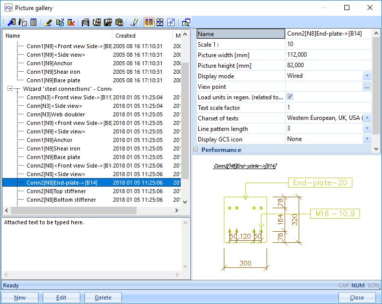
79 Monodrawings It is possible to make automatic connection drawings in SCIA Engineer. To use this option, it is necessary to select the functionality Connection monodrawings : When this option is activated and you have one or more connections in the project, you can right click on the screen and choose for the Picture wizard : 79


80 And choose to generate Steel connections monodrawings : When the drawings are finished, they can be found in the Picture gallery: And here all generated pictures can be found: 80
81 81

![[1]) and the following internal forces: A negative moment will result in tension at the top flange of](/docs-images/88/115488778/images/82-1.jpg "the beam. Calculation V wp,rd : Column web panel in shear V wp,rd 0.")
 t 13140 2 280 18 (10.5 2 24)18 ' 4113 172 10.5 5919 mm ² Vwp, Rd 0.9 235 5919 727,77kN 3 1.")
82 9. Welded connections In this chapter we will show the calculation of a welded connection using example CON_005.esa, node N3. The calculation is done with the Safety factors according the EN (Ref.[1]) and the following internal forces: A negative moment will result in tension at the top flange of the beam. Calculation V wp,rd : Column web panel in shear V wp,rd 0.9f ya 3 M0 vc ' When a web doubler is used: A A A A A vc vc vc vc vc ' A vc b t A 2bt 4113 mm ² s f s ( t w 2r) t ( )18 ' mm ² Vwp, Rd ,77kN And the same is shown in SCIA Engineer: f 82

 F c, fc, Rd c, fc, Rd wc c fc M 0 17.")
83 Calculation F c,wc,rd : Column web in compression F c,wc,rd = ω k wc b eff,c,wc t wc f y,wc γ M0 but F c,wc,rd ω k wc ρ b eff,c,wc t wc f y,wc γ M0 And in SCIA Engineer: Calculation F c,fb,rd : Beam flange in compression F M F c, fb, Rd c, Rd c, fb, Rd M c, Rd h t b M pl, Rd M 0 fb knm knmm 1229 kn Calculation F t,fc,rd : Column flange in bending t wc f y F ( t 2r 7kt ) F c, fc, Rd c, fc, Rd wc c fc M ( ) kn 83

84 Calculation F t,wc,rd : Column web in tension F t b b wc F t, wc, Rd eff eff 1 1.4t t beff t f mm 2a 5 t r (18 24) 252 mm 1 t, wc, Rd fb w 2 wc M 0 y fc beff t wc 11.3 Avc ' kn 1.0 Calculation MRd : Design moment resistance 705 kn x m = 375 knm Calculation af The weld size af is designed according to the resistance of the joint. The design force in the beam flange can be estimated as: M Rd FRd h F Rd kN

85 The design resistance of the weld Fw shall be greater than the flange force FRd, multiplied by a factor. The value of the factor is: = 1.7 for sway frames = 1.4 for non sway frames However, in no case shall the weld design resistance be required to exceed the design plastic resistance of the beam flange Nt.Rd : N N t, Rd t, Rd b f t fb M f yb kn Fw = min ( Nt.Rd, FRd) = min (849, 1.4 x 705)= 849 kn The weld size design for af, using Annex M of EC3 a a f f Fw f b u Mw f W mm We take af=8 mm. In SCIA Engineer 85

 To determine the weld size a 2 in a connection, we use an")
86 Calculation of a w The section is sollicitated by the moment M, the normal force N and the shear force D. The moment M is defined by the critical design moment resistance of the connection. The normal force N is taken as the maximum internal normal force on the node, the shear force D is taken as the maximum internal shear force on the node. M = 375 knm N = 148 kn D = 85 kn (see calculation of MRd and the internal forces, given in the beginning of this chapter) To determine the weld size a 2 in a connection, we use an iterative process with a 2 as parameter until the Von Mises rules is respected: With fu the ultimate tensile strength of the weaker part W the correlation factor Mw the partial safety factor for welds 86
 and the design compression/tension")
87 10. Pinned joints In SCIA Engineer four types of joints are supported : Type 1 Type 2 Type 3 Type 4 welded plate in beam, welded to column bolted plate in beam, welded to column bolted angle in beam and column short endplate welded to beam, bolted in column For each type, the design shear resistance VRd (taking into account the present normal force N) and the design compression/tension resistance NRd are calculated. The design shear resistance is calculated for the following failure modes: - design shear resistance for the connection element - design shear resistance of the beam - design block shear resistance - design shear resistance due to the bolt distribution in the beam web - design shear resistance due to the bolt distribution in the column The design compression/tension resistance is calculated for the following failure modes: - design compression/tension resistance for the connection element - design compression/tension resistance of the beam - design tension resistance due to the bolt distribution in the column In Ref.[2], more info on the used formulas is given Welded fin plate connection In this chapter we will show the calculation of a welded fin plate connection using example CON_009.esa, node N2. The calculation is done with the Safety factors according the EN (Ref.[1]) and the following internal forces: 87

88 Calculation Design Shear Resistance VRd for Connection Element Transversal section of the plate: A pl 2 hpl t pl 3912mm (2 plates) 0,3681 N mm Normal stress: 2 Flexion module: N W N A pl pl 2 t pl h pl mm 6 Design Shear Resistance: a= 163/2 = 81,5 mm is the centre V Rd1 = A f y γ M0 3 = ,00 3 = N = 530,77kN V Rd2 = [ f y σ γ N ] W M0 a = [ ( 0,3681)] = N = 306,92kN 1,00 81,5 V Rd = min(v Rd1 ; V Rd2 ) =306,92kN Calculation Design Shear Resistance VRd for Beam A A 2bt t 2r t 1914,76mm Shear Area : 2 Shear Resistance : VRd v f A f w v y 3 M0 f ,5N 259,79kN Calculation Compression/Tension Resistance NRd for connection element Area of the element : Tension/Compression Resistance : A pl 2h t 3912mm pl pl 2 Apl f y NRd N 919, 32kN M0 88
89 Calculation Design Tension Resistance NRd for Beam 2 Area of the Beam : A m A f y Tension Resistance : N Rd M N 835 kn Weld size Calculation for Plate, Beam and Column To determine the weld size a for the plate on the beam and on the column, we must use a iterative process with a as parameter until the Von Mises rules is respected (Annex M/EC3): fu fu 3 and w M w Mw We ll only check the weld size for the final value of a. For the weld between plate and beam we find a=4mm and for weld between plate and column, the weld size is a=11mm. Weld size Plate/Beam We define the play as the effective distance between the end of the beam and the flange of the column. In this case, the play is 10mm. By using EC3 and the Chapter 11 of the manual, we compute the following parameters: Weld size: a=0.004m Weld Length: l1 hpl 2t pl m l2 bpl Play 2 tpl 0.13m l lpl Play m By EC3: fuw= n/m 2 and w=0.8. The parameters are: a l a l1 l g a l a l a l a l a l a l a l a l a l a l 1.14 a l h pl L 10 g 10104,10 114, 10mm Shear force on one plate: D = V Rd = 259,79 = 129,9kN(for one plate) 2 2 Normal force on one plate: N = N Ed = 1,44 = 0,72kN 2 2 Moment on the plate: M = D L = 129,89 0,1141 = 14,82kNm 6 M N Weld Check 1: , 7 N a l 2 a l mm

90 Unity Check: D 2 70, 97 N a l mm f u 1 w M w and fu Mw 0,35 1 Weld Check 2: , a l2 1 D 1 M 1 N mm N 147, 99 N 2 h a l2 2 a l mm Unity Check: f u 1 w and fu M w M w Weld size Plate/Column Weld size: a=0.011 m Normal Force: N=-1440N=-1,44kN Moment: M D L Nm 21, 3kNm Stress Calculation: N M N D L N 2 mm 2 2 a , a l W 2 2 a l hpl 2 90

91 D 2 76, 68 N 2 a l mm Unity Check: f u 1 w 2 M w f u M w Bolted fin plate connection In this chapter we will show the calculation of a bolted fin plate connection using example CON_010.esa, node N2 for combination C Calculation Design Shear Resistance VRd for Connection Element Transversal section of the plate: 2 2ht mm (2 plates) A v A v,net = A #bolts (t d0) = = 3648mm² N 1440 Normal Stress: 0,32 N N 2 A 4512 mm Flexion Module : 2 t h W mm 6 Bolt Centre : a=34mm (= X1 parameter of the bolt position) 3 The bolt holes are not taken into account when: A v,net f y A OK f u When A v,net is less than this limit, an effective shear area of A v = f u A f v,net may be assumed, else A v = y A Design Shear Resistance: V rd1 = A v f y = = N = 612,76kN γ M0 3 1,00 3 V rd2 = [ f y σ f N ] W u a = [ ( 0,32)] = N = 978,49kN
 = (612,")
92 V rd = min(v rd1 ; V rd2 ) = (612,76; 978,49) = 612,76kN Calculation Design Shear Resistance VRd for Beam Shear Area : A v = A 2 b t f + (t w + 2 r) t f = ( ) 10 = 1872mm² Net Area : A v,net = A v #bolts per section t w d 0 = = 1656mm² The bolt holes are not taken into account when: A v,net f y A f v 1656mm² 1222mm² OK u When A v,net is less than this limit, an effective shear area of A v1 = f u A f v,net may be assumed, else y A v1 = A v Design Shear Resistance: V Rd = A v1 f y = = N = 253,99kN 3 γ M0 3 1, Calculation Design Shear Resistance VRd for Bolt in Beam The calculation of the shear resistance for bolt in beam is based on the following equation to be solve V 2 Rd a c a c a d a N d N 2 V Q Rd 2 n I p n I p I p I p n n a b 0.094m c m d 0.07m Where : m p ri m i1 Q min 2 Fv, Rd,min Fb, Rd, plate; Fb, Rd, beam I 0 = N for two plates, where 0.6 f ub As FV Rd N 30.1kN Mb 2.5 p f u d t Fb,Rd,Beam N 31.7kN Mb with p e1 min 3d 0 p ; 3d ; 4 f f ub u ; p f u d t pl Fb, Rd, plate N Mb 92
93 e1 p1 1 f ub with p min ; ; ; d 0 3d 0 4 f u By solving the second-degree equation, we find VRd 123 kn Calculation Design Block Shear Resistance Vrd - beam The design value of the effective resistance to block shear is determined by the following expression: f y A v,eff Veff,Rd with A v,eff t L v,eff 3 M0 The values a1, a2, a3 and Lv are defined as follows: We determined the effective shear area Av,eff as follows : a 1 50mm a 165mm a 50mm 2 3 L v h a a mm
 240 mm Lv, eff Av, eff t 6 240 1440 mm f y Av, eff Veff, Rd 195375N 195, 38kN 3 M 0 2 10.2.5. Calculation Design Block Shear Resistance")
94 L 3 min Lv a1 a3; Lv a1 a3 n d 0 min 240;257,36 240mm f f u y a ;5 d min( 50;90) mm L1 min f u 360 L2 a 2 k d 0 (165 2,5 18) f 235 y 183,83mm with k 2.5 for 2 bolt - rows Lv, eff min Lv L1 L2; L3 min( 373,83;240) 240 mm Lv, eff Av, eff t mm f y Av, eff Veff, Rd N 195, 38kN 3 M Calculation Design Block Shear Resistance Vrd connection element (beam side) The design value of the effective resistance to block shear is determined by the following expression: f A y v, eff V eff, Rd with Av,eff nt Lv, eff M 3 0 With: n number of plate, cleat t thickness of plate, cleat The values a1, a2, a3 and Lv are defined as follows: We determined the effective shear area Av,eff as follows : a 1 24mm a 155mm a 24mm 2 3 Lv hplate a1 a mm L3 min Lv a1 a3; Lv a1 a3 n d 0 min 188;177,7 177,7mm fu f y 94
95 a ;5 d min( 24;90) mm L1 min fu L2 a2 k d0 (155 2,5 18) f L y with k 2.5 for 2 bolt - rows min Lv L1 L2; L3 min( 342,51;177,7) 168,51mm 177, mm v, eff 7 2 v, eff n t L ,7 4264, 8mm v, eff A f y Av, eff Veff, Rd ,6 N 578, 64kN 3 M 0 Advanced Training Steel Connection Calculation Design Compression/Tension Resistance NRd for Connection Element Area : Net Area : 2 A 2t h mm A net A 2 t 2 d mm Compression Resistance : N Rd = A f y = = N = 1060,32kN γ M0 1, Calculation Design Compression/Tension Resistance NRd for Beam Area : Net Area : 2 A 3912mm A net A 2 t d mm Tension Resistance : min 1,00 A f N Rd min M ,25 0,9 ; y 0.9 A, net 0 M1 f u min( ; ) N 919, 32kN 95


96 10.3. Bolted cleat connection An example of this connection can be found in example CON_011.esa, node N Flexible end plate connection An example of this connection can be found in example CON_012.esa, node N2. 96
97 11. Hollow section joints The design of Hollow Section Joints within SCIA Engineer is implemented according to EN : , including Corrigendum EN :2005/AC: , however for certain parts also different references are taken into account. Such references will be mentioned where relevant. Used terms and symbols are in line with the main code. Open example CON_13.esa Joint configuration The design procedure defined by the EN Article 7, may be applied to joint types specified in EN Article Table 7.1. In SCIA Engineer uniplanar configurations T, Y, X, N, K, DY and DK are currently supported Automatic recognition The automatic recognition of joint configuration is based on the Structural model, taking into account all members selected during input of the joint object. The recognition is processed in several steps: List of all selected members is created. Members with the highest value of Structure type are marked as chord members. User may use for example type truss chord with value of
98 Remaining members are marked as brace members. User may use for example type truss diagonal with value of 90. For each brace member respective delta angle between the brace member and the chord member is measured. The brace member with the smallest delta angle is marked as brace 1. Depending on the number of brace members, an additional delta angles between brace members are measured. The angles are measured in a continuous direction from angle delta 1. See example picture below. The algorithm indicated on the picture below is used for the final determination of the joint configuration. An additional per-plane validation tests need to be fulfilled in the structural model: Axes of all members has to be in one plane. Chord members has to be in line, which in terms means use the same eccentricity For T, Y, X, DY and DK joint configurations, all the members need to have one intersection point. An additional cross-section validation tests need to be fulfilled: For Circular Hollow Section joints, the cross-sections marked by SCIA Engineer as formcode 3 cross-section, are supported. The cross-section id of the chord members have to be identical. An additional geometry validation tests need to be fulfilled in the structural model: Continuous chord members are supported. Continuous brace members are not supported. The curved members are not supported. If the configuration is not recognized, an error massage is displayed during the input of the joint object. User may also modify the geometry or member attributes when a joint already exists and in such case recognized joint configuration is changed to "Not Recognized". 98

99 Gap / Overlap Geometric definition of gap and overlap is given by EN Article 1.5 Figure 1.3. Within SCIA Engineer the Gap / Overlap definition parameters are only valid and displayed for N, K and DK joint configurations. Either gap or overlap is calculated automatically by default using the structural model geometry and the value is shown in the properties of the joint object with reference to identified brace members. The 99

100 formulas for calculation of gap, overlap and also eccentricity are based on a CIDECT publication "Design guide for circular hollow section (CHS) joints under predominantly static loading", 2008: Eccentricity of the joint is defined in EN Article Figure 5.3. The user is also allowed to input direct values of gap or overlap or define it through manual input of eccentricity. This may be done through "Definition" combo-box item in the properties where the user may select from several options: From structural model - Default option. Both gap and overlap is calculated automatically using the structural model geometry. Eccentricity, gap or overlap items are disabled for editing. Eccentricity - Direct input of eccentricity. Gap or overlap is calculated based on the defined eccentricity value and is disabled for editing. Valid input range is <-1;1>[m]. Gap - Direct input of gap. Eccentricity is calculated based on the defined gap value and is disabled for editing. Valid input range is <0;1>[m]. Overlap - Direct input of overlap. Eccentricity is calculated based on the defined overlap value and is disabled for editing. Valid input range is <0;110>[%] Validation tests Redistribution of bending moment caused by eccentricity of brace members As specified in EN Article (6), when brace eccentricities are within the limits given in 5.1.5(5), the moments resulting from the eccentricities should be taken into account in the design of compression chord members. In SCIA Engineer the redistribution for such case is done in several steps: The moment caused by eccentricity of braces is calculated as : M y,0,ecc = N i cos θ i e With: Ni θi e design normal force in the brace angle between the brace and chord members brace eccentricity 100
101 The chord sides in compression are identified. The side is recognized to be in compression if the formula below produces a positive result. The internal forces from the respective section closest to the the joint node are used in the formula. σ = N Ed A 0 With: + M y,0,ed + M z,0,ed W el,y,0 W el,z,0 NEd A0 My,0,Ed Wel,y,0 Mz,0,Ed Wel,z,0 design normal force in the chord at a joint chord cross-section area design bending moment around y-axis in the chord at a joint elastic section modulus of chord cross-section around y-axis design bending moment around z-axis in the chord at a joint elastic section modulus of chord cross-section around z-axis If no chord side in compression is found, no redistribution is done and a warning is displayed in the detailed the output. Ratio for each chord side in compression is calculated based on the number of chord sides in compression. If only one side of chord is in compression the ratio for that side is set to 1 however if two sides of chord is in compression are found, the moment caused by eccentricity of braces is equally redistributed to both sides using coefficient 0,5. Iy,I Li Iy,(i+1) L(i+1) moment of inertia for 1st chord side in compression system length of the member on 1st chord side in compression moment of inertia for 2nd chord side in compression system length of the member on 2nd chord side in compression Additional moments for each of the compression sides of a chord are calculated and added to initial internal forces of the respective side. As specified by EN Article (8) these additional moments, resulting in additional stresses, are taken into account in the determination of the factors km, kn and kp used in the design of the joint. As specified in EN Article (7), when the eccentricities are outside the limits given in 5.1.5(5), the moments resulting from the eccentricities should be taken into account in the design of the joints and the members. In this case the moments produced by the eccentricity should be distributed between all the members meeting at the joint, on the basis of their relative stiffness coefficients I/L. In SCIA Engineer for such case no redistribution is done and warning is displayed in the detailed output. The reason for this is that the redistribution of additional moment should be done in more elaborated way (FEM analysis) General scope and field of application As specified in EN Article the method application is valid both for hot hollow sections to EN and for cold formed hollow sections to EN This is not checked by SCIA Engineer and is responsibility of the user to ensure that this is fulfilled. Following items are verified by SCIA Engineer: General criteria for the joint members given by EN Article 7.1.1: The nominal yield strength should not exceed 460MPa. If yield strength higher than 355MPa, the static design resistances should be reduced by factor 0,9. The nominal wall thickness of hollow sections should not be less than 2,5mm. The nominal wall thickness of hollow section chord should not be greater than 25mm unless special measures have been taken. General field of application for joint members are given in EN Article 7.1.2: 101

102 The compression elements of the members should satisfy the requirements for Class 1 or Class 2 given in EN for the condition of axial compression. The angle θi between the chords and the brace members, and between adjacent brace members, should be equal or bigger than 30 degrees. In gap joints, the gap between the brace members should not be less than (t1+t2). Based on TATA Steel publications also maximum limit of 12*t0 is checked. In overlap type joints, the overlap should be at least 25% in order to be bale place welds. If the overlap is larger than 60% in case hidden seam of the overlapped brace is not welded or larger than 80% in case hidden seam of the overlapped brace is welded, a warning requesting additional shear check is displayed. Where overlapping brace members have different thickness and/or different strength grades, the member with the lower (ti*fy,i) value should overlap the other member. Where overlapping brace members are of different widths, the narrower member should overlap the wider one. Not fulfilling any of the tests above will result in a displayed error after a chapter with geometry tests and termination of the check part! The exception are the tests for the yield strength of 355 MPa, eccentricity and maximum overlap limit. These exceptions will result in warning messages in the respective validation parts Range of validity for CHS chord and CHS brace members The EN Article Table 7.1 specifies an additional range of validity tests for the CHS chord joints. All the items above are verified by SCIA Engineer. Not fulfilling any of the tests above will result in a displayed error after a chapter with geometry tests and termination of the check part! The exception is the test for maximum overlap limit. This exceptions will result in warning message in the validation part. 102
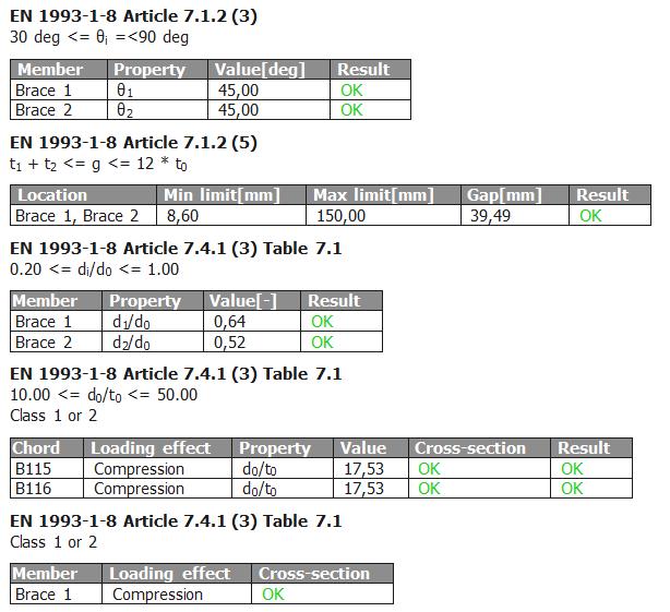
103 103

104 11.3. Design resistance The general criteria for steel member present in the hollow section joint are specified in EN Article (1-2). The design values of the internal axial forces both in the brace members and in the chords at the ultimate limit state shall not exceed the design resistances of the members determined from EN In order to check this the user should run steel check. The design values of the internal axial forces in the brace members at the ultimate limit state shall also not exceed the design resistances of the joints given in design tables as appropriate. This is calculated and verified by the hollow section joint. 104

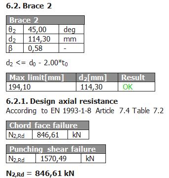
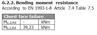
105 105
BASE PLATE CONNECTIONS
 SKILLS Project BASE PLATE CONNECTIONS LEARNING OUTCOMES Design process for pinned and fixed column base joints Base-plate resistance Anchor bolt resistance Concrete resistance Weld resistance Application
SKILLS Project. October 2013
 SKILLS Project October 2013 MOMENT CONNECTIONS PART 1 LEARNING OUTCOMES Design process for moment-resisting bolted connections Joint moment resistance Joint stiffness Details design (welds, bolts, stiffeners,
Autodesk Robot Structural Analysis Professional 2014 Design of fixed beam-to-column connection EN :2005/AC:2009
 Autodesk Robot Structural Analysis Professional 2014 Design of fixed beam-to-column connection EN 1993-1-8:2005/AC:2009 Ratio 0,44 GENERAL Connection no.: 24 Connection name: Ligação 2 Structure node:
SIMPLIFIED FORMULAS FOR ASSESSMENT OF STEEL JOINT FLEXIBILITY CHARACTERISTICS
 SIMPLIFIED FORMULAS FOR ASSESSMENT OF STEEL JOINT FLEXIBILITY CHARACTERISTICS Aleksander Kozłowski; Lucjan Ślęczka Rzeszów University of Technology, Poland kozlowsk@prz.edu.pl, sleczka@prz.edu.pl ABSTRACT
Joint resistance M j,rd Elastic limit 2/3 M j,rd
 6 OENT CONNECTIONS 6.1 Introduction The moment connections are transferring, except of shear and normal forces, bending moment (full or partial compare to connected element) to supports. Stiffness of connection
GENERAL GEOMETRY LEFT SIDE BEAM RIGHT SIDE BS :2000/AC:2009. Ratio 0.17
 Autodesk Robot Structural Analysis Professional 2015 Design of fixed beam-to-beam connection BS 5950-1:2000/AC:2009 Ratio 0.17 GENERAL Connection no.: 2 Connection name: Beam-Beam Structure node: 40 Structure
TAMPERE UNIVERSITY OF TECHNOLOGY ELENA RUEDA ROMERO FINITE ELEMENT SIMULATION OF A BOLTED STEEL JOINT IN FIRE USING ABAQUS PROGRAM
 TAMPERE UNIVERSITY OF TECHNOLOGY ELENA RUEDA ROMERO FINITE ELEMENT SIMULATION OF A BOLTED STEEL JOINT IN FIRE USING ABAQUS PROGRAM Master of Science Thesis Examiners: Professor Markku Heinisuo and Mr.
A CONNECTION ELEMENT FOR MODELLING END-PLATE CONNECTIONS IN FIRE
 A CONNECTION ELEMENT OR MODELLING END-PLATE CONNECTIONS IN IRE Dr Zhaohui Huang Department of Civil & Structural Engineering, University of Sheffield 22 September 29 1. INTRODUCTION Three approaches for
Joints in steel construction: Moment-resisting joints to eurocode 3
 Joints in steel construction: Moment-resisting joints to eurocode 3 SCI (The Steel Construction Institute) is the leading, independent provider of technical expertise and disseminator of best practice
Equivalent T-stubs (Component Method) as per DIN EN
 as per DIN EN") Equivalent T-stubs (Component Method) as per DIN EN 1993-1-8 Nemetschek Frilo GmbH www.frilo.de info@frilo.de As of 23/11/2012 Contents Introduction 3 T-stub model 3 Examples for the T-stub model 9 Introduction
Equivalent T-stubs (Component Method) as per DIN EN 1993-1-8 Nemetschek Frilo GmbH www.frilo.de info@frilo.de As of 23/11/2012 Contents Introduction 3 T-stub model 3 Examples for the T-stub model 9 Introduction
Structural Steelwork Eurocodes Development of A Trans-national Approach
 Structural Steelwork Eurocodes Development of A Trans-national Approach Course: Eurocode Module 7 : Worked Examples Lecture 0 : Simple braced frame Contents: 1. Simple Braced Frame 1.1 Characteristic Loads
Structural Steelwork Eurocodes Development of A Trans-national Approach
 Structural Steelwork Eurocodes Development of A Trans-national Approach Course: Eurocode Module 7 : Worked Examples Lecture 22 : Design of an unbraced sway frame with rigid joints Summary: NOTE This example
ON THE DESIGN OF A STEEL END-PLATE BEAM-TO-COLUMN BOLTED JOINT ACCORDING TO PN-EN
 CZASOPISMO INŻYNIERII LĄDOWEJ, ŚRODOWISKA I ARCHITEKTURY JOURNAL O CIVIL ENGINEERING, ENVIRONMENT AND ARCHITECTURE JCEEA, t. XXXV, z. 65 (2/18), kwiecień-czerwiec 2018, s. 187-196, DOI:10.7862/rb.2018.35
Application nr. 7 (Connections) Strength of bolted connections to EN (Eurocode 3, Part 1.8)
 Strength of bolted connections to EN (Eurocode 3, Part 1.8)") Application nr. 7 (Connections) Strength of bolted connections to EN 1993-1-8 (Eurocode 3, Part 1.8) PART 1: Bolted shear connection (Category A bearing type, to EN1993-1-8) Structural element Tension
Application nr. 7 (Connections) Strength of bolted connections to EN 1993-1-8 (Eurocode 3, Part 1.8) PART 1: Bolted shear connection (Category A bearing type, to EN1993-1-8) Structural element Tension
Structural Steelwork Eurocodes Development of A Trans-national Approach
 Structural Steelwork Eurocodes Development of A Trans-national Approach Course: Eurocode 3 Module 7 : Worked Examples Lecture 20 : Simple braced frame Contents: 1. Simple Braced Frame 1.1 Characteristic
A Simplified Method for the Design of Steel Beam-to-column Connections
 P P Periodica Polytechnica Architecture A Simplified Method for the Design of Steel Beam-to-column Connections 48() pp. 79-86 017 https://doi.org/10.3311/ppar.11089 Creative Commons Attribution b Imola
University of Sheffield. Department of Civil Structural Engineering. Member checks - Rafter 44.6
 Member checks - Rafter 34 6.4Haunch (UB 457 x 191 x 89) The depth of a haunch is usually made approximately twice depth of the basic rafter sections, as it is the normal practice to use a UB cutting of
Structural Steelwork Eurocodes Development of a Trans-National Approach
 Course: Eurocode 4 Structural Steelwork Eurocodes Development of a Trans-National Approach Lecture 9 : Composite joints Annex B References: COST C1: Composite steel-concrete joints in frames for buildings:
Finite Element Modelling with Plastic Hinges
 01/02/2016 Marco Donà Finite Element Modelling with Plastic Hinges 1 Plastic hinge approach A plastic hinge represents a concentrated post-yield behaviour in one or more degrees of freedom. Hinges only
CONNECTIONS WITH FOUR BOLTS PER HORIZONTAL ROW Application of Eurocode 3
 EUROSTEEL 0 August 3 - September 0 Budapest Hungary CONNECTIONS WITH FOUR BOLTS PER HORIZONTAL ROW Application of Eurocode 3 Jean-François Demonceau a Jean-Pierre Jaspart a Klaus Weynand b Ralf Oerder
DESIGN OF END PLATE JOINTS SUBJECT TO MOMENT AND NORMAL FORCE
 DESIGN OF END PLATE JOINTS SUBJECT TO OENT AND NORAL FORCE Zdeněk Sokol 1, František Wald 1, Vincent Delabre 2, Jean-Pierre ueau 2, arek Švarc 1 ABSTRACT The presented work describes design model of end
Fundamentals of Structural Design Part of Steel Structures
 Fundamentals of Structural Design Part of Steel Structures Civil Engineering for Bachelors 133FSTD Teacher: Zdeněk Sokol Office number: B619 1 Syllabus of lectures 1. Introduction, history of steel structures,
A component model for the behaviour of steel joints at elevated temperatures
 Journal of Constructional Steel Research 57 (2001) 1169 1195 www.elsevier.com/locate/jcsr A component model for the behaviour of steel joints at elevated temperatures L. Simões da Silva a,*, Aldina Santiago
3. Stability of built-up members in compression
 3. Stability of built-up members in compression 3.1 Definitions Build-up members, made out by coupling two or more simple profiles for obtaining stronger and stiffer section are very common in steel structures,
IDEA StatiCa Connection
 IDEA StatiCa Connection Theoretical background October 2016 Content 1 Introduction... 4 2 CBFEM components... 5 2.1 Material model... 6 2.2 Plate model and mesh convergence... 8 2.2.1 Plate model... 8
PROFILE SIZES: CONNECTION FORCES BEAM : UB254X146X43 CONNECTION DETAIL: D b = mm W b = mm T b = mm t wb = 7.30 mm r b = 7.
 PROFILE SIZES: BEAM : UB254X146X43 D b = 259.60 mm W b = 147.30 mm T b = 12.70 mm t wb = 7.30 mm r b = 7.60 mm COLUMN : UC254X254X73 D C = 254.00 mm W c = 254.00 mm T C = 14.20 mm t wc = 8.60 mm r C =
Project data Project name Project number Author Description Date 26/04/2017 Design code AISC dome anchor. Material.
 Project data Project name Project number Author Description Date 26/04/2017 Design code AISC 360-10 Material Steel A36, A529, Gr. 50 Concrete 4000 psi dome anchor Connection Name Description Analysis Design
STEEL BUILDINGS IN EUROPE. Multi-Storey Steel Buildings Part 8: Description of member resistance calculator
 STEEL BUILDINGS IN EUROPE Multi-Store Steel Buildings Part 8: Description of member resistance calculator Multi-Store Steel Buildings Part : Description of member resistance calculator 8 - ii FOREWORD
VALLOUREC & MANNESMANN TUBES. Design-support for MSH sections
 VALLOUREC & MANNESMANN TUBES Design-support for MSH sections according to Eurocode 3, DIN EN 1993-1-1: 2005 and DIN EN 1993-1-8: 2005 Design-Support for MSH sections according to Eurocode 3, DIN EN 1993-1-1:
QUESTION BANK DEPARTMENT: CIVIL SEMESTER: III SUBJECT CODE: CE2201 SUBJECT NAME: MECHANICS OF SOLIDS UNIT 1- STRESS AND STRAIN PART A
 DEPARTMENT: CIVIL SUBJECT CODE: CE2201 QUESTION BANK SEMESTER: III SUBJECT NAME: MECHANICS OF SOLIDS UNIT 1- STRESS AND STRAIN PART A (2 Marks) 1. Define longitudinal strain and lateral strain. 2. State
QUESTION BANK SEMESTER: III SUBJECT NAME: MECHANICS OF SOLIDS
 QUESTION BANK SEMESTER: III SUBJECT NAME: MECHANICS OF SOLIDS UNIT 1- STRESS AND STRAIN PART A (2 Marks) 1. Define longitudinal strain and lateral strain. 2. State Hooke s law. 3. Define modular ratio,
Application nr. 3 (Ultimate Limit State) Resistance of member cross-section
 Resistance of member cross-section") Application nr. 3 (Ultimate Limit State) Resistance of member cross-section 1)Resistance of member crosssection in tension Examples of members in tension: - Diagonal of a truss-girder - Bottom chord of
Application nr. 3 (Ultimate Limit State) Resistance of member cross-section 1)Resistance of member crosssection in tension Examples of members in tension: - Diagonal of a truss-girder - Bottom chord of
STEEL BUILDINGS IN EUROPE. Multi-Storey Steel Buildings Part 10: Technical Software Specification for Composite Beams
 STEEL BUILDINGS IN EUROPE Multi-Storey Steel Buildings Part 10: Technical Software Specification for Composite Beams Multi-Storey Steel Buildings Part 10: Technical Software Specification for Composite
Accordingly, the nominal section strength [resistance] for initiation of yielding is calculated by using Equation C-C3.1.
![Accordingly, the nominal section strength [resistance] for initiation of yielding is calculated by using Equation C-C3.1.](/thumbs/89/98617066.jpg "Accordingly, the nominal section strength [resistance] for initiation of yielding is calculated by using Equation C-C3.1.") C3 Flexural Members C3.1 Bending The nominal flexural strength [moment resistance], Mn, shall be the smallest of the values calculated for the limit states of yielding, lateral-torsional buckling and distortional
C3 Flexural Members C3.1 Bending The nominal flexural strength [moment resistance], Mn, shall be the smallest of the values calculated for the limit states of yielding, lateral-torsional buckling and distortional
IDEA StatiCa Connection
 IDEA StatiCa Connection Theoretical background March 2017 Content 1 Introduction... 4 2 CBFEM components... 5 2.1 Material model... 6 2.2 Plate model and mesh convergence... 8 2.2.1 Plate model... 8 2.2.2
Advanced Analysis of Steel Structures
 Advanced Analysis of Steel Structures Master Thesis Written by: Maria Gulbrandsen & Rasmus Petersen Appendix Report Group B-204d M.Sc.Structural and Civil Engineering Aalborg University 4 th Semester Spring
STEEL JOINTS - COMPONENT METHOD APPLICATION
 Bulletin of the Transilvania University of Braşov Vol. 5 (54) - 2012 Series 1: Special Issue No. 1 STEEL JOINTS - COPONENT ETHOD APPLICATION D. RADU 1 Abstract: As long as the rotation joint stiffness
COMPUTERISED CALCULATION OF FORCE DISTRIBUTIONS IN BOLTED END PLATE CONNECTIONS ACCORDING TO EUROCODE 3 1
 COUTERISED CALCULATION OF FORCE DISTRIBUTIONS IN BOLTED END LATE CONNECTIONS ACCORDING TO EUROCODE 3 artin Steenhuis Cock Dol Leon van Gorp TNO Building and Construction Research, Lange Kleiweg 5, 2288
Influence of residual stresses in the structural behavior of. tubular columns and arches. Nuno Rocha Cima Gomes
 October 2014 Influence of residual stresses in the structural behavior of Abstract tubular columns and arches Nuno Rocha Cima Gomes Instituto Superior Técnico, Universidade de Lisboa, Portugal Contact:
KINGS COLLEGE OF ENGINEERING DEPARTMENT OF MECHANICAL ENGINEERING QUESTION BANK. Subject code/name: ME2254/STRENGTH OF MATERIALS Year/Sem:II / IV
 KINGS COLLEGE OF ENGINEERING DEPARTMENT OF MECHANICAL ENGINEERING QUESTION BANK Subject code/name: ME2254/STRENGTH OF MATERIALS Year/Sem:II / IV UNIT I STRESS, STRAIN DEFORMATION OF SOLIDS PART A (2 MARKS)
PLATE GIRDERS II. Load. Web plate Welds A Longitudinal elevation. Fig. 1 A typical Plate Girder
 16 PLATE GIRDERS II 1.0 INTRODUCTION This chapter describes the current practice for the design of plate girders adopting meaningful simplifications of the equations derived in the chapter on Plate Girders
Design of a Steel I-section for Bending, Shear and Axial Force
 Benchmark Example No. 20 Design of a Steel I-section for Bending, Shear and Axial Force SOFiSTiK 2018 VERiFiCATiON MANUAL DCE-EN20: Design of a Steel I-section for Bending, Shear and Axial Force VERiFiCATiON
Design of Steel Structures Prof. S.R.Satish Kumar and Prof. A.R.Santha Kumar. Local buckling is an extremely important facet of cold formed steel
 5.3 Local buckling Local buckling is an extremely important facet of cold formed steel sections on account of the fact that the very thin elements used will invariably buckle before yielding. Thinner the
1C8 Advanced design of steel structures. prepared by Josef Machacek
 1C8 Advanced design of steel structures prepared b Josef achacek List of lessons 1) Lateral-torsional instabilit of beams. ) Buckling of plates. 3) Thin-walled steel members. 4) Torsion of members. 5)
JointsForTekla Ver January
 Ing. Giovanni Conticello Ing. Sebastiano Floridia With the important help of Ing. Giovanni Trigili JointsForTekla Ver. 1.11.0.59 - January 23 2014 Design of joints of steel structures in environment TeklaStructures
Annex 1: Symbols and units
 Annex 1: Symbols and units A1.1 Symbols The terms and words used in this Code carry the meaning normally assigned within the area of structural steel, and are generally defined the first time they appear
Sabah Shawkat Cabinet of Structural Engineering Walls carrying vertical loads should be designed as columns. Basically walls are designed in
 Sabah Shawkat Cabinet of Structural Engineering 17 3.6 Shear walls Walls carrying vertical loads should be designed as columns. Basically walls are designed in the same manner as columns, but there are
Metal Structures Lecture XIII Steel trusses
 Metal Structures Lecture XIII Steel trusses Contents Definition #t / 3 Geometry and cross-sections #t / 7 Types of truss structures #t / 15 Calculations #t / 29 Example #t / 57 Results of calculations
BLOCK SHEAR CONNECTION DESIGN CHECKS
 REF: ASI TN013 Version 1 ASI Head Office Level 13, 99 Mount Street North Sydney NSW 2060 Tel: 02 9931 6666 Email: enquiries@steel.org.au (ABN)/ACN (94) 000973 839 www.steel.org.au ASI TECHNICAL NOTE TN013
Structural Steelwork Eurocodes Development of a Trans-National Approach
 Structural Steelwork Eurocodes Development of a Trans-National Approach Course: Eurocode 4 Lecture 9 : Composite joints Annex A Summary: Traditionally structural joints are considered as rigid or pinned
Design of Compression Members
 Design of Compression Members 2.1 Classification of cross sections Classifying cross-sections may mainly depend on four critical factors: 1- Width to thickness (c/t) ratio. 2- Support condition. 3- Yield
Downloaded from Downloaded from / 1
 PURWANCHAL UNIVERSITY III SEMESTER FINAL EXAMINATION-2002 LEVEL : B. E. (Civil) SUBJECT: BEG256CI, Strength of Material Full Marks: 80 TIME: 03:00 hrs Pass marks: 32 Candidates are required to give their
Job No. Sheet 1 of 6 Rev B. Made by IR Date Oct Checked by FH/NB Date Oct Revised by MEB Date April 2006
 Job No. Sheet 1 of 6 Rev B, Route de Limours Tel : (0)1 0 85 5 00 Fax : (0)1 0 5 75 8 Revised by MEB Date April 006 DESIGN EXAMPLE 6 BOLTED JOINT A 0 0 angle loaded in tension is to be connected to a gusset
C6 Advanced design of steel structures
 C6 Advanced design of steel structures prepared b Josef achacek List of lessons 1) Lateral-torsional instabilit of beams. ) Buckling of plates. 3) Thin-walled steel members. 4) Torsion of members. 5) Fatigue
Steel connections. Connection name : MEP_BCF_W=14.29[mm]_W=6.35[mm]_tp=63.5[mm]_N=0_N=2_N=0_N=1_W=14.29[mm]_W=14.29[mm]_W=14.29[ mm] Connection ID : 1
![Steel connections. Connection name : MEP_BCF_W=14.29[mm]_W=6.35[mm]_tp=63.5[mm]_N=0_N=2_N=0_N=1_W=14.29[mm]_W=14.29[mm]_W=14.29[ mm] Connection ID : 1](/thumbs/96/127718340.jpg "Steel connections. Connection name : MEP_BCF_W=14.29[mm]_W=6.35[mm]_tp=63.5[mm]_N=0_N=2_N=0_N=1_W=14.29[mm]_W=14.29[mm]_W=14.29[ mm] Connection ID : 1") Current Date: 08-Dec-13 7:05 PM Units system: SI File name: E:\ram\1\1.cnx\ Microsoft Steel connections Detailed report Connection name : MEP_BCF_W=14.29[mm]_W=6.35[mm]_tp=63.5[mm]_N=0_N=2_N=0_N=1_W=14.29[mm]_W=14.29[mm]_W=14.29[
Current Date: 08-Dec-13 7:05 PM Units system: SI File name: E:\ram\1\1.cnx\ Microsoft Steel connections Detailed report Connection name : MEP_BCF_W=14.29[mm]_W=6.35[mm]_tp=63.5[mm]_N=0_N=2_N=0_N=1_W=14.29[mm]_W=14.29[mm]_W=14.29[
TOPIC TRAINING CODE CHECK COLD-FORMED STEEL PROFILES
 TOPIC TRAINING CODE CHECK COLD-FORMED STEEL PROFILES All information in this document is subject to modification without prior notice. No part of this manual may be reproduced, stored in a database or
Design of Beams (Unit - 8)
") Design of Beams (Unit - 8) Contents Introduction Beam types Lateral stability of beams Factors affecting lateral stability Behaviour of simple and built - up beams in bending (Without vertical stiffeners)
Design of Beams (Unit - 8) Contents Introduction Beam types Lateral stability of beams Factors affecting lateral stability Behaviour of simple and built - up beams in bending (Without vertical stiffeners)
Influence of column web stiffening on the seismic behaviour of beam-tocolumn
 Influence of column web stiffening on the seismic behaviour of beam-tocolumn joints A.L. Ciutina & D. Dubina The Politehnica University of Timisoara, Romania ABSTRACT: The present paper summarises the
my!wind Ltd 5 kw wind turbine Static Stability Specification
 my!wind Ltd 5 kw wind turbine Static Stability Specification 1 P a g e 0 3 / 0 4 / 2 0 1 4 Contents Contents... 2 List of Changes... 2 Appendixes... 2 General remarks... 3 1. Introduction... 4 2. Geometry...
Verification of a Micropile Foundation
 Engineering manual No. 36 Update 02/2018 Verification of a Micropile Foundation Program: File: Pile Group Demo_manual_en_36.gsp The objective of this engineering manual is to explain the application of
C:\Users\joc\Documents\IT\Robot EC3 6_2_1 (5)\Eurocode _2_1(5) Concentrated Load - Rev 1_0.mcdx. γ M γ M γ M2 1.
\Eurocode _2_1(5) Concentrated Load - Rev 1_0.mcdx. γ M γ M γ M2 1.") C:\Users\joc\Documents\IT\Robot EC3 6 1 (5)\Eurocode 1993-1-1 6 1(5) Concentrated Load - Rev 1_0.mcdx Page 1 of 01/03/016 Section sec HEB500 with steel grade gr S355 I x Iy_sec (sec) cm 4 = 10700 cm 4
C:\Users\joc\Documents\IT\Robot EC3 6 1 (5)\Eurocode 1993-1-1 6 1(5) Concentrated Load - Rev 1_0.mcdx Page 1 of 01/03/016 Section sec HEB500 with steel grade gr S355 I x Iy_sec (sec) cm 4 = 10700 cm 4
Shear Behaviour of Fin Plates to Tubular Columns at Ambient and Elevated Temperatures
 Shear Behaviour of Fin Plates to Tubular Columns at Ambient and Elevated Temperatures Mark Jones Research Student, University of Manchester, UK Dr. Yong Wang Reader, University of Manchester, UK Presentation
T2. VIERENDEEL STRUCTURES
 T2. VIERENDEEL STRUCTURES AND FRAMES 1/11 T2. VIERENDEEL STRUCTURES NOTE: The Picture Window House can be designed using a Vierendeel structure, but now we consider a simpler problem to discuss the calculation
my!wind Ltd 5 kw wind turbine Static Stability Specification
 my!wind Ltd 5 kw wind turbine Static Stability Specification 1 P a g e 0 3 / 0 4 / 2 0 1 4 Contents Contents... 2 List of Changes... 2 Appendixes... 2 General remarks... 3 1. Introduction... 4 2. Geometry...
D e s i g n o f R i v e t e d J o i n t s, C o t t e r & K n u c k l e J o i n t s
 D e s i g n o f R i v e t e d J o i n t s, C o t t e r & K n u c k l e J o i n t s 1. Design of various types of riveted joints under different static loading conditions, eccentrically loaded riveted joints.
CALCULATION MODE FOR ALUHD23/SH18 Traction and shear aluminium plate for Alufoot R system
 CALCULATION MODE FOR ALUHD23/SH18 Traction and shear aluminium plate for Alufoot R system INTRODUCTION ALUHD23/SH18 plate, being part of Alufoot system, is used in order to connect the CLT wall to the
Steel Frame Design Manual
 Steel Frame Design Manual Eurocode 3-1:2005 with 8:2004 Eurocode 3-1:2005 with Eurocode 8:2004 Steel Frame Design Manual for ETABS 2016 ISO ETA122815M13 Rev 0 Proudly developed in the United States of
FLEXIBILITY METHOD FOR INDETERMINATE FRAMES
 UNIT - I FLEXIBILITY METHOD FOR INDETERMINATE FRAMES 1. What is meant by indeterminate structures? Structures that do not satisfy the conditions of equilibrium are called indeterminate structure. These
Component Method for Base Plate
 Component ethod for Base Plate Wald F.; Sokol Z. Cech Technical University, Faculty of Civil Engineering Steenhuis C.. Eindhoven University of Technology, Faculty of Architecture, Building and Planning,
FINITE ELEMENT ANALYSIS OF THE ROTATION CAPACITY OF BEAM-TO-COLUMN END-PLATE BOLTED JOINT
 EUROSTEEL 2014, September 10-12, 2014, Naples, Italy FINITE ELEMENT ANALYSIS OF THE ROTATION CAPACITY OF BEAM-TO-COLUMN END-PLATE BOLTED JOINT Krzysztof Ostrowski Design Office MTA Engineering Ltd., Rzeszów,
SIMPLE MODEL FOR PRYING FORCES IN T-HANGER CONNECTIONS WITH SNUG TIGHTENED BOLTS
 SIMPLE MODEL FOR PRYING FORCES IN T-HANGER CONNECTIONS WITH SNUG TIGHTENED BOLTS By Fathy Abdelmoniem Abdelfattah Faculty of Engineering at Shoubra, Zagazig University, Banha Branch Mohamed Salah A. Soliman
ARCHIVES OF CIVIL ENGINEERING, LIX, 4, 2013 CALCULATION OF WELDING TRUSSES OVERLAP JOINTS MADE OF RECTANGULAR HOLLOW SECTIONS 1.
 DOI:.478/ace--4 ARCHIVES OF CIVIL ENGINEERING, LIX, 4, CALCULATION OF WELDING TRUSSES OVERLAP JOINTS MADE OF RECTANGULAR HOLLOW SECTIONS J. BRÓDKA, M. BRONIEWICZ The basis for calculating of resistance
March 24, Chapter 4. Deflection and Stiffness. Dr. Mohammad Suliman Abuhaiba, PE
 Chapter 4 Deflection and Stiffness 1 2 Chapter Outline Spring Rates Tension, Compression, and Torsion Deflection Due to Bending Beam Deflection Methods Beam Deflections by Superposition Strain Energy Castigliano
3 Hours/100 Marks Seat No.
 *17304* 17304 14115 3 Hours/100 Marks Seat No. Instructions : (1) All questions are compulsory. (2) Illustrate your answers with neat sketches wherever necessary. (3) Figures to the right indicate full
USFOS. Joint Capacity. Theory Description of use Verification
 USFOS Joint Capacity Theory Description of use Verification Table of Contents 1. INTRODUCTION... 4 1.1 General... 4 1. MSL variants... 4 1.3 Code variants... 4. THEORY... 6.1 Joint capacity formulas...
The subject of this paper is the development of a design
 The erformance and Design Checking of Chord-Angle Legs in Joist Girders THEODORE V. GALAMBOS ABSTRACT The subject of this paper is the development of a design checking method for the capacity of the outstanding
PERIYAR CENTENARY POLYTECHNIC COLLEGE PERIYAR NAGAR - VALLAM THANJAVUR. DEPARTMENT OF MECHANICAL ENGINEERING QUESTION BANK
 PERIYAR CENTENARY POLYTECHNIC COLLEGE PERIYAR NAGAR - VALLAM - 613 403 - THANJAVUR. DEPARTMENT OF MECHANICAL ENGINEERING QUESTION BANK Sub : Strength of Materials Year / Sem: II / III Sub Code : MEB 310
TORSION INCLUDING WARPING OF OPEN SECTIONS (I, C, Z, T AND L SHAPES)
") Page1 TORSION INCLUDING WARPING OF OPEN SECTIONS (I, C, Z, T AND L SHAPES) Restrained warping for the torsion of thin-wall open sections is not included in most commonly used frame analysis programs. Almost
Page1 TORSION INCLUDING WARPING OF OPEN SECTIONS (I, C, Z, T AND L SHAPES) Restrained warping for the torsion of thin-wall open sections is not included in most commonly used frame analysis programs. Almost
Tekla Structural Designer 2016i
 Tekla Structural Designer 2016i Reference Guides (Australian Codes) September 2016 2016 Trimble Solutions Corporation part of Trimble Navigation Ltd. Table of Contents Analysis Verification Examples...
LOAD BEARING CAPACITY OF SPLICED COLUMNS WITH SINGLE ROW BOLTED BUTT-PLATES
 LOAD BEARING CAPACITY OF SPLICED COLUMNS WITH SINGLE ROW BOLTED BUTT-PLATES J.C.D. Hoenderkamp, H. H. Snijder Eindhoven University of Technology, The Netherlands j.c.d.hoenderkamp@tue.nl h.h.snijder@tue.nl
UNIT-I STRESS, STRAIN. 1. A Member A B C D is subjected to loading as shown in fig determine the total elongation. Take E= 2 x10 5 N/mm 2
 UNIT-I STRESS, STRAIN 1. A Member A B C D is subjected to loading as shown in fig determine the total elongation. Take E= 2 x10 5 N/mm 2 Young s modulus E= 2 x10 5 N/mm 2 Area1=900mm 2 Area2=400mm 2 Area3=625mm
MS Excel Toolkit: Design of steel-concrete composite columns in accordance with EN
 MS Excel Toolkit: Design of steel-concrete composite columns in accordance with EN 1994-1-1 Guilherme de Azevedo Guedes Lebre Dissertation in Civil Engineering, Master Degree Instituto Superior Técnico,
7 STATICALLY DETERMINATE PLANE TRUSSES
 7 STATICALLY DETERMINATE PLANE TRUSSES OBJECTIVES: This chapter starts with the definition of a truss and briefly explains various types of plane truss. The determinancy and stability of a truss also will
CONNECTION DESIGN. Connections must be designed at the strength limit state
 CONNECTION DESIGN Connections must be designed at the strength limit state Average of the factored force effect at the connection and the force effect in the member at the same point At least 75% of the
CIVIL DEPARTMENT MECHANICS OF STRUCTURES- ASSIGNMENT NO 1. Brach: CE YEAR:
 MECHANICS OF STRUCTURES- ASSIGNMENT NO 1 SEMESTER: V 1) Find the least moment of Inertia about the centroidal axes X-X and Y-Y of an unequal angle section 125 mm 75 mm 10 mm as shown in figure 2) Determine
Job No. Sheet 1 of 7 Rev A. Made by ER/EM Date Feb Checked by HB Date March 2006
 Job No. Sheet of 7 Rev A Design Example Design of a lipped channel in a Made by ER/EM Date Feb 006 Checked by HB Date March 006 DESIGN EXAMPLE DESIGN OF A LIPPED CHANNEL IN AN EXPOSED FLOOR Design a simply
Design of Steel Structures Prof. Damodar Maity Department of Civil Engineering Indian Institute of Technology, Guwahati
 Design of Steel Structures Prof. Damodar Maity Department of Civil Engineering Indian Institute of Technology, Guwahati Module 7 Gantry Girders and Plate Girders Lecture - 3 Introduction to Plate girders
UNIT 1 STRESS STRAIN AND DEFORMATION OF SOLIDS, STATES OF STRESS 1. Define stress. When an external force acts on a body, it undergoes deformation.
 UNIT 1 STRESS STRAIN AND DEFORMATION OF SOLIDS, STATES OF STRESS 1. Define stress. When an external force acts on a body, it undergoes deformation. At the same time the body resists deformation. The magnitude
Effective stress method to be used in beam finite elements to take local instabilities into account
 Effective stress method to be used in beam finite elements to take local instabilities into account JEAN-MARC FRANSSEN, BAPTISTE COWEZ and THOMAS GERNAY ArgencoDepartment University of Liège Chemin des
SRI CHANDRASEKHARENDRA SARASWATHI VISWA MAHAVIDHYALAYA
 SRI CHANDRASEKHARENDRA SARASWATHI VISWA MAHAVIDHYALAYA (Declared as Deemed-to-be University under Section 3 of the UGC Act, 1956, Vide notification No.F.9.9/92-U-3 dated 26 th May 1993 of the Govt. of
Example 4: Design of a Rigid Column Bracket (Bolted)
") Worked Example 4: Design of a Rigid Column Bracket (Bolted) Example 4: Design of a Rigid Column Bracket (Bolted) Page : 1 Example 4: Design of a Rigid Column Bracket (Bolted) Determine the size of the
Worked Example 4: Design of a Rigid Column Bracket (Bolted) Example 4: Design of a Rigid Column Bracket (Bolted) Page : 1 Example 4: Design of a Rigid Column Bracket (Bolted) Determine the size of the
R13. II B. Tech I Semester Regular Examinations, Jan MECHANICS OF SOLIDS (Com. to ME, AME, AE, MTE) PART-A
 PART-A") SET - 1 II B. Tech I Semester Regular Examinations, Jan - 2015 MECHANICS OF SOLIDS (Com. to ME, AME, AE, MTE) Time: 3 hours Max. Marks: 70 Note: 1. Question Paper consists of two parts (Part-A and Part-B)
SET - 1 II B. Tech I Semester Regular Examinations, Jan - 2015 MECHANICS OF SOLIDS (Com. to ME, AME, AE, MTE) Time: 3 hours Max. Marks: 70 Note: 1. Question Paper consists of two parts (Part-A and Part-B)
THE DEVELOPMENT OF A COMPONENT-BASED CONNECTION ELEMENT FOR ENDPLATE CONNECTIONS IN FIRE
 THE DEVELOPMENT OF A COMPONENT-BASED CONNECTION ELEMENT FOR ENDPLATE CONNECTIONS IN FIRE FLORIAN BLOCK 1, IAN BURGESS 2, BUICK DAVISON 3 and ROGER PLANK 4 ABSTRACT This paper describes the development
Tension Members. ENCE 455 Design of Steel Structures. II. Tension Members. Introduction. Introduction (cont.)
") ENCE 455 Design of Steel Structures II. Tension Members C. C. Fu, Ph.D., P.E. Civil and Environmental Engineering Department University of Maryland Tension Members Following subjects are covered: Introduction
ENCE 455 Design of Steel Structures II. Tension Members C. C. Fu, Ph.D., P.E. Civil and Environmental Engineering Department University of Maryland Tension Members Following subjects are covered: Introduction
MODULE C: COMPRESSION MEMBERS
 MODULE C: COMPRESSION MEMBERS This module of CIE 428 covers the following subjects Column theory Column design per AISC Effective length Torsional and flexural-torsional buckling Built-up members READING:
Experimental investigation on monotonic performance of steel curved knee braces for weld-free beam-to-column connections
 Experimental investigation on monotonic performance of steel curved knee braces for weld-free beam-to-column connections *Zeyu Zhou 1) Bo Ye 2) and Yiyi Chen 3) 1), 2), 3) State Key Laboratory of Disaster
1C8 Advanced design of steel structures. prepared by Josef Machacek
 1C8 Advanced design of steel structures prepared b Josef Machacek List of lessons 1) Lateral-torsional instabilit of beams. ) Buckling of plates. 3) Thin-alled steel members. ) Torsion of members. 5) Fatigue
ADVANCED CONCEPT TRAINING
 ADVANCED CONCEPT TRAINING ALUMINIUM CODE CHECK Advanced Concept Training Aluminium Code Check All information in this document is subject to modification without prior notice. No part of this manual may
The plastic moment capacity of a composite cross-section is calculated in the program on the following basis (BS 4.4.2):
:") COMPUTERS AND STRUCTURES, INC., BERKELEY, CALIFORNIA SEPTEMBER 2002 COMPOSITE BEAM DESIGN BS 5950-90 Technical Note Composite Plastic Moment Capacity for Positive Bending This Technical Note describes
COMPUTERS AND STRUCTURES, INC., BERKELEY, CALIFORNIA SEPTEMBER 2002 COMPOSITE BEAM DESIGN BS 5950-90 Technical Note Composite Plastic Moment Capacity for Positive Bending This Technical Note describes
Schöck Isokorb Type S22 and S16
 Schöck Isokorb Type S22 and S16 Figure 1. Schöck Isokorb Type S22 The Schöck Isokorb Type S22 and S16 is used to transmit axial and shear forces in a steel connection. The combination of multiple modules