BEAM IMPEDANCE. Olav Berrig / CERN. Lanzhou China May 2018 CERN-ACC-SLIDES /05/2018
|
|
|
- Magdalene Booker
- 5 years ago
- Views:
Transcription

1 BEAM IMPEDANCE Olav Berrig / CERN CERN-ACC-SLIDES /05/2018 Lanzhou China May
2 Outline 1. What is beam impedance? 2. Beam impedance is modelled as a lumped impedance 3. New formula for longitudinal beam impedance 4. Panofsky-Wenzel theorem and transverse impedance 5. Lab measurements of beam impedance 2
3 What is beam impedance? Beam impedance is just a normal impedance. However, it is very difficult to understand beam impedance because it is not a lumped impedance but measured over a length. In addition it is defined as the difference in impedance between an accelerator equipment and a straight vacuum chamber. The straight vacuum chamber must have constant cross-section; have the same length as the accelerator equipment and have walls that are superconducting (also called perfectly conducting PEC). A particle moving in a straight vacuum chamber with constant crosssection and superconducting walls have no beam 3 impedance.
4 What is beam impedance? An accelerator without beam impedance does not have instabilities. Beam impedance is not our friend! Beam impedance gives the beam a kick i.e. a disturbing force acting on the beam. The beam impedance forces will make the beam oscillate, just like a mass suspended between springs: NB! Landau damping is not shown because it is not damping, in spite of the name! Synchrotron radiation Beam Damping kicker 4
5 What is beam impedance? An example of transverse impedance, that gives the beam a transverse kick! Here measured with the beam Andrea Latina Hao Zha s Ref [1]
6 What is beam impedance? There are many types of beam impedance: Beam impedance from the currents in the walls of accelerator equipment (beam coupling impedance): 1) Resistive wall impedance 2) Geometric impedance Space charge beam impedance 1) Direct space charge impedance 2) Indirect space charge impedance Damping kicker impedance, Electron cloud, impedance, 6
7 What is beam impedance? There are many types of beam impedance: Beam impedance from the currents in the walls of accelerator equipment (beam coupling impedance): 1) Resistive wall impedance 2) Geometric impedance Space charge beam impedance 1) Direct space charge impedance 2) Indirect space charge impedance In the following, I will only talk about beam coupling impedance Damping kicker impedance, Electron cloud, impedance, 7

8 What is beam impedance? The wall currents must oppose the beam current, so that the fields outside the vacuum chamber are zero 8
9 What is beam impedance? Equipment PEC vacuum pipe When we calculate the beam impedance for an equipment, we compare the equipment to a perfectly conducting (PEC) vacuum chamber with the same dimensions at start and end. 9

10 What is beam impedance? Classical thick wall regime: R = w L Current density estimation J [A/m 2 ] skin depth This area represents the difference between superconducting (PEC) vacuum chamber and one with resistance. b b+ B [Tesla] m 0 I 2pb b b+ Curtesy of M.Migliorati 10
 (-60, 30) (-60,-30) ( 60,-30) (-40, 7) ( 40, 7) (-40, -7) ( 40, -7) Ohm 80 60 40 CST_freq Theory HFSS_freq CST_Wakefield Collimator:")
11 What is beam impedance? Skin depth: ( 60, 30) (-60, 30) (-60,-30) ( 60,-30) (-40, 7) ( 40, 7) (-40, -7) ( 40, -7) Ohm CST_freq Theory HFSS_freq CST_Wakefield Collimator: Length: 200 mm Width: 120 mm Height: 60 mm Electrical conductivity of jaws: σ = 100 S/m Rad s 11
12 Beam impedance: R + j w L versus R i w L Circuit definition American Fourier Chinese and European Fourier R + j w L R + j w L R i w L In my experience, accelerator components have only resistive and inductive coupling impedance. 12
13 Beam impedance modelled as lumped impedance Definition of beam impedance: = Voltage over equipment Drive particle act as a current. (It s a Dirac delta function) Definition of lumped impedance: Z(w) Dirac Delta, where h(t) h(t) = impulse response 13
14 Beam What impedance is beam impedance? modelled by lumped impedance The wake function W (t) is the equipment response function, i.e. the response to a Dirac delta function. The impedance is, according to normal theory, just the Fourier transform of the response function: 14
15 Beam What impedance is beam impedance? modelled by lumped impedance In other texts (See e.g. Ref. [6]) one will often find this definition: 15

16 Beam impedance modelled by lumped impedance Wall currents generate electro-magnetic fields i.e. photons when bend along the cavity walls. Photons The electro-magnetic fields stays in the cavity and generates a resonance, which will disturb i.e. kick the following bunch. A resonance is modeled as a RLC-circuit: RLC-circuit definition used for resonance ( American Fourier) Z (w) = ò 0 k loss = 1 2p W (t )e jwt dt ò 0 Â{ Z (w)}dw w 0 = 1 LC ; Q = R C L R Z (w) = 1+ jq(w w 0 -w 0 w) k loss = w 0 4 R Q The bigger R/Q the bigger the energy loss. NB! This definition of the loss factor is only valid for a bunch that is a dirac delta function. The more general definition will be given later. The energy lost, is equal to the loss factor k loss multiplied with the square of the charge of the bunch: 16
17 New formula for longitudinal beam impedance The Longitudinal beam impedance is a function of the transverse position of the drive and test particles i.e. 4 variables. It can therefore be decomposed into 15 parameters (Z0, Z1 xd, Z1 xt, etc..) that represent all combinations of the 4 variables: 17
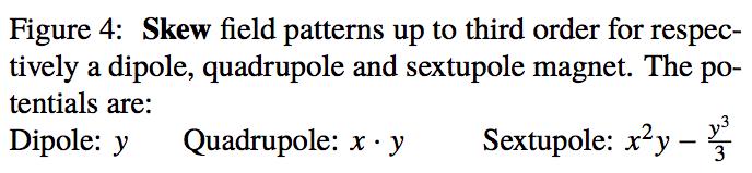
18 New formula for longitudinal beam impedance Holomorphic decomposition: Any two dimensional field, and very importantly a field that can really exist (so not an artificially constructed field), can be decomposed into multipolar components. This is the same idea used in Fourier transforms. The holomorphic decomposition expands the field into normal and skew multipolar functions: Zero order first order second order NB! Notice that the coefficients for x squared and y squared are same numerical value but opposite signs 18

19 New formula for longitudinal beam impedance The normal and skew multipolar functions are well known from accelerator magnets: Zero order first order second order 19
20 New formula for longitudinal beam impedance Using the holomorphic decomposition for both the drive and test particles, knowing that the coefficients for the squared values of xd & yd and xt & yt must be of opposite sign, the formula can be reduced to 13 terms: 20
21 New formula for longitudinal beam impedance Using a property, called the Lorentz reciprocity principle, which says that if we exchange the positions of the drive and test particles, the beam impedance stays unchanged, i.e.. This leads to 5 equalities: The new formula for longitudinal beam impedance finally has only 8 terms: 21
22 New formula for longitudinal beam impedance Using a property, called the Lorentz reciprocity principle, which says that if we exchange the positions of the drive and test particles, the beam impedance stays unchanged, i.e.. This leads to 5 equalities: The new formula for longitudinal beam impedance finally has only 8 terms: Quadrupolar term 22
23 New formula for longitudinal beam impedance Using a property, called the Lorentz reciprocity principle, which says that if we exchange the positions of the drive and test particles, the beam impedance stays unchanged, i.e.. This leads to 5 equalities: The new formula for longitudinal beam impedance finally has only 8 terms: Quadrupolar term Dipolar terms H & V 23
24 What is beam impedance? The longitudinal beam impedance have 8 parameters Interchanging the drive and test particles, will give the same beam impedance. It is caused by the Lorentz reciprocity theorem (well known to RF people as the identity S21 S12): 24
25 What is beam impedance? The longitudinal beam impedance have 8 parameters The Lorentz reciprocity theorem is responsible for coupling primary and secondary windings in a transformer: 25
26 What is beam impedance? The longitudinal beam impedance have 8 parameters The Lorentz reciprocity theorem is responsible for coupling primary and secondary windings in a transformer: This is why the name of a beam impedance that is generated by the wall currents is a beam coupling impedance 26

27 What is beam impedance? The longitudinal beam impedance have 8 parameters The new formula shows that 90 degree symmetrical structures only have dipolar impedance and that this impedance is the same in all directions 27
28 New formula for longitudinal beam impedance This new formula is not valid for resonances nor for non-relativistic beams, because both are spread out in 3D. The formula is practically valid for beams with, even though theoretically there will always be other terms, but these terms are proportional to, so will not be important in practice: 28
29 Panofsky-Wenzel and transverse impedance The rigid bunch approximation states that the beam motion is little affected during the passage through the structure. So the beam shape is rigid and it always moves unchanged with the bunch. Wakefield The force acting on the test particle: Using Maxwell s equations: 29
30 Panofsky-Wenzel and transverse impedance The force acting on the test particle: Very important: Because the wakefield is only a function of s then: B(s) This leads to Position of drive particle: Position of the test particle: When inserting the partial differentials on the right, the terms in the bracket cancels out and gives zero. 30
31 Panofsky-Wenzel and transverse impedance The force acting on the test particle: Very important: Because the wakefield is only a function of s then: B(s) This leads to Position of drive particle: Position of the test particle: Panofsky Wenzel theorem When inserting the partial differentials on the right, the terms in the bracket cancels out and gives zero. 31


32 Panofsky-Wenzel and transverse impedance To obtain the theorem in terms of impedance, one can simply start from the wake function form: Then change the derivative with the time derivative. Use : Finally take the Fourier transform on both sides: NB! The transverse impedance is defined with a complex factor: Panofsky Wenzel theorem 32
33 Panofsky-Wenzel and transverse impedance Using the following definitions: and 33
34 Panofsky-Wenzel and transverse impedance Using the following definitions: and Panofsky Wenzel theorem In differential form 34
35 Panofsky-Wenzel and transverse impedance Because of the rigid bunch approximation, which states that the beam motion is little affected during the passage through a structure, the wake field is the same before and after the passage of an equipment. Therefore, it is as if B is only a function of s. A criterion for the Panofsky-Wenzel theorem is therefore that the vacuum chamber has to have the same cross-section before and after the equipment otherwise the B-field is not the same. 35
36 Lab measurements of beam impedance. Wire #1 We can measure the beam impedance with wire measurements This is based on the assumption that a bunch interacts with an equipment in exactly the same way as a coaxial cable (i.e. a wire inside the equipment): Ultra-relativistic beam field TEM mode coax waveguide See A.Mostacci: 36
37 Lab measurements of beam impedance. Wire #2 Network analyzer Port 1 dz/dl Network analyzer Port 2 DUT=Device under test wire dz/dl wire REF = Reference = PEC vacuum 37 chamber same length as DUT

38 Lab measurements of beam impedance. Wire #3 Beam impedance: This is the improved log formula, which is used for wire measurements 38

39 Lab measurements of beam impedance. Wire #4 39
40 Lab measurements of beam impedance. Wire #5 B 50 Ω B 50 Ω 180 o Hybrid A B C D A B C D 40
41 Lab measurements of beam impedance. Wire #6 Characteristic impedance distance between them Two wire measurement give only the dipolar impedance of two wires, each with diameter and with is (See Example: = 10.0 mm Z = 120/1. ln(40) ~ 450 Ohm d = 0.5 mm i.e. 225 Ohm per wire Subtract 50 Ohm, as usual, this gives 175 Ohm per wire. So it is always 175 Ohm per wire 41 independent of the chamber diameter!
42 Lab measurements of beam impedance. Wire #7 Two wire measurement give only the dipolar impedance +a -a = dipolar impedance The distance between the wires is 2 a: A B C D A B C D 42
43 Another What is measure beam impedance? of transverse beam impedance! An example of transverse impedance, that gives the beam a transverse kick! Here measured with the beam Andrea Latina Hao Zha s Ref [1]
44 Lab measurements of beam impedance. Wire #8 Easy method to firmly straighten the wire. Make hole in connector and solder a thin wire to the resistor. This method was invented by Muzhaffar Hazman 44


45 Lab measurements of beam impedance. Wire #8 Easy method to firmly straighten the wire. Make hole in connector and solder a thin wire to the resistor. When soldering the resistor to the connector, keep the other soldering cold, otherwise it will dissolve. Use plier as heat sink. This method was invented by Muzhaffar Hazman 45
46 Lab What measurements is beam impedance? of beam impedance. Wire #9 46
47 Lab measurements of beam impedance. Wire #10 ab-note pdf T. Kroyer, F. Caspers, E. Gaxiola MKE Kicker measurements 47

48 Lab measurements of beam impedance. Wire #11 An example of serigraphy in the SPS Extraction Kicker Magnets (SPS-MKE) 48

49 Lab measurements of beam impedance. Wire #12 Kicker Transition piece, i.e. keep electrical connection with the vacuum chamber 49
50 Lab measurements of beam impedance. Wire #13 Kicker Transition piece, i.e. keep electrical connection with the vacuum chamber 50

51 Lab measurements of beam impedance. Wire #14 Collimator measurement /attachments/ / /SLAC_RC_SPS_pla n.pdf N. Biancacci, P. Gradassi, T. Markiewicz, S. Redaelli, B. Salvant, G. Valentino 51
52 Lab measurements of beam impedance. Probe #1 52
53 Lab measurements of beam impedance. Probe #2 53

54 Lab measurements of beam impedance. Probe #3 54
55 Lab measurements of beam impedance. Probe #4 smith chart 55
56 Lab measurements. Measure Q reflection. Probe #5 A resonance is a circle in the smith diagram. Three different types of Q: 1) The loaded Q (QL) 2) The unloaded Q (Q0) 3) The Q of the external world (Qext ). We want Q 0, but we can only measure Q L and b: 56


57 Lab measurements. Measure Q reflection. Probe #6 Ql β 2 Q Ql β 2 Q Courtesy of C.Vollinger and T.Kaltenbacher 57
58 Beam impedance presentation. Lanzhou - China 感谢您的关注 58
59 [1] Measurement of transverse kick in CLIC accelerating structure in FACET Hao Zha, Andrea Latina, Alexej Grudiev [2] Holomorphic decomposition. John Jowett \\cern.ch\dfs\projects\ilhc\mathematicaexamples\accelerator\multipolefields.nb [3] On single wire technique for transverse coupling impedance measurement. H. Tsutsui [4] Longitudinal instability of a coasting beam above transition, due to the action of lumped discontinuities V. Vaccaro [5] Wake Fields and Instabilities Mauro Migliorati [6] G.Rumolo, CAS Advanced Accelerator Physics Trondheim, Norway August [7] THE STRETCHED WIRE METHOD: A COMPARATIVE ANALYSIS PERFORMED BY MEANS OF THE MODE MATCHING TECHNIQUE M.R.Masullo, V.G.Vaccaro, M.Panniello [7] Two Wire Wakefield Measurements of the DARHT Accelerator Cell. Scott D. Nelson, Michael Vella [8] Shunt impedance, RLC-circuit definition, Accelerator definition, Alexej Grudiev [9] A.Mostacci [10] COUPLING IMPEDANCE MEASUREMENTS: AN IMPROVED WIRE METHOD V.Vaccaro [11] Interpretation of coupling impedance bench measurements H. Hahn [12] Measurement of coupling impedance of accelerator devices with the wire-method J.G. Wang, S.Y. Zhang 59
60 [13] Longitudinal and Transverse Wire Measurements for the Evaluation of Impedance Reduction Measures on the MKE Extraction Kickers. Kroyer, T ; Caspers, Friedhelm ; Gaxiola, E 60
61 Energy loss when beam pass through an equipment Shunt impedance, RLC-circuit definition, Accelerator definition, Alexej Grudiev In the following, only beam coupling impedance are calculated. Beam coupling impedance is generated by the currents in the walls of the equipment, and is the only significant impedance in high energy accelerators. 61
62 Beam impedance modelled by lumped impedance Shunt impedance, RLC-circuit definition, Accelerator definition, Alexej Grudiev 62
63 What is beam impedance? The longitudinal beam impedance have 8 parameters The beam impedance is now decomposed into 13 parameters : Z [xd, xt, yd, yt] = Z0 +Z1XD xd+z1xt xt+z1yd yd+z1yt yt +Z2XYDXYD (xd 2 -yd 2 )+Z2XYTXYT (xt 2 - yt 2 ) +Z2XDXT xd xt+z2xdyd xd yd+z2xdyt xd yt +Z2XTYD xt yd+z2xtyt xt yt+z2ydyt yd yt The new formula is identical to the previous from Tsutsui: 63

64 What is beam impedance? The longitudinal beam impedance have 8 parameters xd=0,yd=0.0020,xt=0.0025,yt=0 xd=0.001,yd=0.0025,xt=0,yt=0 xd=0.0025,yd=0,xt=0,yt= xd=0,yd=0,xt=0.001,yt= Real Imaginary Real Imaginary Interchanging the drive and test particles always give the same beam impedance. CST 64
65 What is beam impedance? The longitudinal beam impedance have 8 parameters Z [xd, xt, yd, yt] = Z0 +Z1X (xd+xt)+z1y (yd+yt) +Z2XYDTXYDT (xd 2 +xt 2 -yd 2 - yt 2 ) +Z2XDTYDT (xd yd+xt yt) +Z2XDTYTD (xd yt +xt yd) +Z2XDXT xd xt+z2ydyt yd yt 65

66 What is beam impedance? CST Wakefield example illustrating the 8 parameters Z2YTIm,Z2YDIm Z2YTRe,Z2YDRe Prediction: Z2XYDTXYDT (xd 2 +xt 2 -yd 2 - yt 2 ) CST Z2XTRe,Z2XDRe Z2XTIm,Z2XDIm 66

67 What is beam impedance? CST Wakefield example illustrating the 8 parameters Prediction: Z2XDTYDT (xd yd+xt yt) CST Z2XTYTIm, Z2XDYDIm Z2XTYTRe, Z2XDYDRe 67

68 What is beam impedance? CST Wakefield example illustrating the 8 parameters Prediction: Z2XDTYTD (xd yt +xt yd) CST Z2XTYDRe, Z2XDYTRe,Z2XTYDIm, Z2XDYTIm 68

69 What is beam impedance? CST Wakefield example illustrating the 8 parameters Prediction versus simulation 3 examples Example 1: yd=2.5, yt=2.5 Example 2: xd=1.0, yd=2.5 Example 3: xd=-1.5, yd=2.0, xt=2.5 CST Prediction Real Prediction Imaginary Simulation Real Simulation Imaginary 69
70 What is beam impedance? The rotating wire method One wire represents the drive particle and the other wire represents the test particle. In this measurement, we do not have a positive current in one wire and a negative current in the other Both wires are measured individually i.e. single-ended In the additional slide, it is demonstrated how this measurement can derive all 8 parameters
71 What is beam impedance? The rotating wire method Some implications of the new 8 parameter formula: 1) Transverse impedance The offset term is not automatically zero, depends on the shape of the equipment 2) Transverse impedance Is it possible to shape a collimator e.g. in three-fold symmetric form so that its transvers impedance is zero up to second order? 3) Transverse impedance The beam oscillates during instability, is it possible to shape equipment 71 in such a way that the drive position works against the instability?
72 Supporting material for slide 72
73 73


74 74

75 75
CERN Accelerator School Wakefields. Prof. Dr. Ursula van Rienen, Franziska Reimann University of Rostock
 CERN Accelerator School Wakefields Prof. Dr. Ursula van Rienen, Franziska Reimann University of Rostock Contents The Term Wakefield and Some First Examples Basic Concept of Wakefields Basic Definitions
Impedance & Instabilities
 Impedance & Instabilities The concept of wakefields and impedance Wakefield effects and their relation to important beam parameters Beam-pipe geometry and materials and their impact on impedance An introduction
Frequency and time domain analysis of trapped modes in the CERN Proton Synchrotron
 Frequency and time domain analysis of trapped modes in the CERN Proton Synchrotron Serena Persichelli CERN Impedance and collective effects BE-ABP-ICE Abstract The term trapped mode refers to a resonance
Beam instabilities (I)
") Beam instabilities (I) Giovanni Rumolo in CERN Accelerator School, Advanced Level, Trondheim Wednesday 21.08.2013 Big thanks to H. Bartosik, G. Iadarola, K. Li, N. Mounet, B. Salvant, R. Tomás, C. Zannini
Beam instabilities (I) Giovanni Rumolo in CERN Accelerator School, Advanced Level, Trondheim Wednesday 21.08.2013 Big thanks to H. Bartosik, G. Iadarola, K. Li, N. Mounet, B. Salvant, R. Tomás, C. Zannini
Studies of trapped modes in the new extraction septum of the CERN Proton Synchrotron
 Studies of trapped modes in the new extraction septum of the CERN Proton Synchrotron Serena Persichelli CERN Impedance and collective effects (BE-ABP-ICE) LIU LHC Injectors Upgrade project Università di
INSTABILITIES IN LINACS. Massimo Ferrario INFN-LNF
 INSTABILITIES IN LINACS Massimo Ferrario INFN-LNF Trondheim, 4 August, 13 SELF FIELDS AND WAKE FIELDS Direct self fields Image self fields Space Charge Wake fields γ = 1 1 β E = q 4πε o ( 1 β ) ( 1 β sin
CERN Accelerator School. RF Cavities. Erk Jensen CERN BE-RF
 CERN Accelerator School RF Cavities Erk Jensen CERN BE-RF CERN Accelerator School, Varna 010 - "Introduction to Accelerator Physics" What is a cavity? 3-Sept-010 CAS Varna/Bulgaria 010- RF Cavities Lorentz
INSTABILITIES IN LINACS
 INSTABILITIES IN LINACS Massimo Ferrario INFN-LNF Trieste, 2-142 October 2005 Introduction to Wake Fields Instability in Linacs:Beam Break Up Circular Perfectly Conducting Pipe - Beam at Center- Static
UPDATE OF THE SPS KICKERS
 UPDATE OF THE SPS KICKERS B. Salvant and E. Métral APC action (0//06): The Committee but it stressed the importance of evaluating the effect of the resonance peaks observed at low frequency on the longitudinal
General wall impedance theory for 2D axisymmetric and flat multilayer structures
 General wall impedance theory for 2D axisymmetric and flat multilayer structures N. Mounet and E. Métral Acknowledgements: N. Biancacci, F. Caspers, A. Koschik, G. Rumolo, B. Salvant, B. Zotter. N. Mounet
Single-Bunch Effects from SPX Deflecting Cavities
 Single-Bunch Effects from SPX Deflecting Cavities Yong-Chul Chae and Louis Emery Accelerator Operation Group Accelerator System Division Measurements March 13, 2013 Introduction The single bunch current
IMPEDANCE THEORY AND MODELING
 Proceedings of ICFA Mini-Workshop on pedances and Beam Instabilities in Particle Accelerators, Benevento, Italy, 8-22 September 27, CERN Yellow ports: Conference Proceedings, Vol. /28, CERN-28-3-CP (CERN,
Elias Métral, LHC Collimation Working Group Meeting, 15/03/ /31
 Answers to Jeff and Liling concerning the simulations of trapped modes of the SLAC Phase 2 collimator, and news on impedance for the Phase 1 and 2 at CERN Reminder on the trapped modes simulations performed
TRANSVERSE IMPEDANCE OF LHC COLLIMATORS
 Contributed talk WEOAC03 (12 + 3 min, 14 slides) TRANSVERSE IMPEDANCE OF LHC COLLIMATORS Elias Métral Work in collaboration with G. Arduini,, R. Assmann,, A. Boccardi,, T. Bohl, F. Caspers,, M. Gasior,,
Coupling Impedance of Ferrite Devices Description of Simulation Approach
 Coupling Impedance of Ferrite Devices Description of Simulation Approach 09 May 2012 TU Darmstadt Fachbereich 18 Institut Theorie Elektromagnetischer Felder Uwe Niedermayer 1 Content Coupling Impedance
Index. Accelerator model 8 Adiabatic damping 32, 141 Air-bag model 338 Alternating explicit time scheme 112 Azimuthal modes, see Modes
 Index Accelerator model 8 Adiabatic damping 32, 141 Air-bag model 338 Alternating explicit time scheme 112 Azimuthal modes, see Modes Beam breakup in linacs dipole mode 136 higher modes 160 quadrupole
RF coupling impedance measurements versus simulations
 RF coupling impedance measurements versus simulations Abstract A. Mostacci, L. Palumbo, Università La Sapienza, Roma, Italy B. Spataro, LNF-INFN, Frascati, Italy, F. Caspers, CERN, Geneva, Switzerland.
Accelerator Physics. Tip World Scientific NEW JERSEY LONDON SINGAPORE BEIJING SHANGHAI HONG KONG TAIPEI BANGALORE. Second Edition. S. Y.
 Accelerator Physics Second Edition S. Y. Lee Department of Physics, Indiana University Tip World Scientific NEW JERSEY LONDON SINGAPORE BEIJING SHANGHAI HONG KONG TAIPEI BANGALORE Contents Preface Preface
BEAM INSTABILITIES IN LINEAR MACHINES 2
 BEAM INSTABILITIES IN LINEAR MACHINES 2 Massimo.Ferrario@LNF.INFN.IT CERN 5 November 215 ( ) σ " + k 2 s σ = k sc s,γ σ Equilibrium solution: ( ) = k sc( s,γ ) σ eq s,γ k s Single Component Relativistic
Wakefields and Impedances I. Wakefields and Impedances I
 Wakefields and Impedances I Wakefields and Impedances I An Introduction R. Wanzenberg M. Dohlus CAS Nov. 2, 2015 R. Wanzenberg Wakefields and Impedances I CAS, Nov. 2015 Page 1 Introduction Wake Field
Transverse beam stability and Landau damping in hadron colliders
 Work supported by the Swiss State Secretariat for Educa6on, Research and Innova6on SERI Transverse beam stability and Landau damping in hadron colliders C. Tambasco J. Barranco, X. Buffat, T. Pieloni Acknowledgements:
SPS IMPEDANCE BUDGET
 SPS IMPEDANCE BUDGET G. Arduini,, H. Medina, E. Métral, B. Salvant and B. Spataro ZBASE Items considered until now Kickers BPMs Pumping ports Theoretical predictions and comparison with measurements of
Evaluation of In-Vacuum Wiggler Wakefield Impedances for SOLEIL and MAX IV
 26/11/2014 European Synchrotron Light Source Workshop XXII 1 Evaluation of In-Vacuum Wiggler Wakefield Impedances for SOLEIL and MAX IV F. Cullinan, R. Nagaoka (SOLEIL, St. Aubin, France) D. Olsson, G.
Instabilities Part III: Transverse wake fields impact on beam dynamics
 Instabilities Part III: Transverse wake fields impact on beam dynamics Giovanni Rumolo and Kevin Li 08/09/2017 Beam Instabilities III - Giovanni Rumolo and Kevin Li 2 Outline We will close in into the
Physics 598ACC Accelerators: Theory and Applications
 Physics 598ACC Accelerators: Theory and Instructors: Fred Mills, Deborah Errede Lecture 6: Collective Effects 1 Summary A. Transverse space charge defocusing effects B. Longitudinal space charge effects
Calculation of Wakefields and Higher Order Modes for the New Design of the Vacuum Chamber of the ALICE Experiment for the HL-LHC
 CERN-ACC-NOTE-2017-0033 23rd May 2017 rainer.wanzenberg@desy.de Calculation of Wakefields and Higher Order Modes for the New Design of the Vacuum Chamber of the ALICE Experiment for the HL-LHC R. Wanzenberg
Measurement of the Transverse Resistive-Wall Impedance of a LHC Graphite Collimator at Low Frequency
 Measurement of the Transverse Resistive-Wall Impedance of a LHC Graphite Collimator at Low Frequency, Cockcroft Institute and University of Manchester F.Caspers, T.Kroyer, E.Métral, B.Salvant CERN HB2008,
AN IMPROVED LOG-FORMULA FOR HOMOGENEOUSLY DISTRIBUTED IMPEDANCE
 EUROPEAN ORGANIZATION FOR NUCLEAR RESEARCH ORGANISATION EUROPEENNE POUR LA RECHERCHE NUCLEAIRE CERN - PS DIVISION PS/RF/Note 2-1 AN IMPROVED LOG-FORMULA FOR HOMOGENEOUSLY DISTRIBUTED IMPEDANCE E. Jensen
Accelerator Physics NMI and Synchrotron Radiation. G. A. Krafft Old Dominion University Jefferson Lab Lecture 16
 Accelerator Physics NMI and Synchrotron Radiation G. A. Krafft Old Dominion University Jefferson Lab Lecture 16 Graduate Accelerator Physics Fall 17 Oscillation Frequency nq I n i Z c E Re Z 1 mode has
Task 2.4 on LHC Collective Effects Studies
 Task 2.4 on LHC Collective Effects Studies Requested info: Detailed workflow, including milestones, expected deliverables and delivery dates => See also https://espace.cern.ch/hilumi/wp2/task4/ SitePages/Home.aspx
Electromagnetic Oscillations and Alternating Current. 1. Electromagnetic oscillations and LC circuit 2. Alternating Current 3.
 Electromagnetic Oscillations and Alternating Current 1. Electromagnetic oscillations and LC circuit 2. Alternating Current 3. RLC circuit in AC 1 RL and RC circuits RL RC Charging Discharging I = emf R
Simulations of single bunch collective effects using HEADTAIL
 Simulations of single bunch collective effects using HEADTAIL G. Rumolo, in collaboration with E. Benedetto, O. Boine-Frankenheim, G. Franchetti, E. Métral, F. Zimmermann ICAP, Chamonix, 02.10.2006 Giovanni
Wake Fields in Particle Accelerators with Finite Thickness and Conductivity
 FACOLTÀ DI INGEGNERIA Corso di Laurea in Ingegneria delle Telecomunicazioni Tesi di Laurea Wake Fields in Particle Accelerators with Finite Thickness and Conductivity Relatore: Prof. Stefania Petracca
Beam heat load due to geometrical and resistive wall impedance in COLDDIAG
 Beam heat load due to geometrical and resistive wall impedance in COLDDIAG Sara Casalbuoni, Mauro Migliorati, Andrea Mostacci, Luigi Palumbo, Bruno Spataro 2012 JINST 7 P11008, http://iopscience.iop.org/17480221/7/11/p11008
Review of proposals of ERL injector cryomodules. S. Belomestnykh
 Review of proposals of ERL injector cryomodules S. Belomestnykh ERL 2005 JLab, March 22, 2005 Introduction In this presentation we will review injector cryomodule designs either already existing or under
Measurement of wakefields in hollow plasma channels Carl A. Lindstrøm (University of Oslo)
") Measurement of wakefields in hollow plasma channels Carl A. Lindstrøm (University of Oslo) in collaboration with Spencer Gessner (CERN) presented by Erik Adli (University of Oslo) FACET-II Science Workshop
Measurement of wakefields in hollow plasma channels Carl A. Lindstrøm (University of Oslo) in collaboration with Spencer Gessner (CERN) presented by Erik Adli (University of Oslo) FACET-II Science Workshop
Transverse dynamics Selected topics. Erik Adli, University of Oslo, August 2016, v2.21
 Transverse dynamics Selected topics Erik Adli, University of Oslo, August 2016, Erik.Adli@fys.uio.no, v2.21 Dispersion So far, we have studied particles with reference momentum p = p 0. A dipole field
ILC Beam Dynamics Studies Using PLACET
 ILC Beam Dynamics Studies Using PLACET Andrea Latina (CERN) July 11, 2007 John Adams Institute for Accelerator Science - Oxford (UK) Introduction Simulations Results Conclusions and Outlook PLACET Physical
A SCALING LAW DERIVED FROM A BROADBAND IMPEDANCE APPLICATION TO SPEAR
 Particle Accelerators, 1990, Vol. 25, pp. 235-240 Reprints available directly from the publisher Photocopying permitted by license only 1990 Gordon and Breach, Science Publishers, Inc. Printed in the United
HL LHC: impedance considerations for the new triplet layout in IR1 & 5
 HL LHC: impedance considerations for the new triplet layout in IR1 & 5 N. Mounet, A. Mostacci, B. Salvant, C. Zannini and E. Métral Acknowledgements: G. Arduini, C. Boccard, G. Bregliozzi, L. Esposito,
High performance computing simulations. for multi-particle effects in the synchrotons
 High performance computing simulations for multi-particle effects in the synchrotons Content What is the HSC section doing? Physics basics PyHEADTAIL software Simulations of the PS Simulations of instabilities
BEAM SCREEN ISSUES (with 20 T dipole magnets instead of 8.3 T)
") BEAM SCREEN ISSUES (with 20 T dipole magnets instead of 8.3 T) Introduction and current LHC beam screen Magneto-Resistance (MR) What was done in the past (approx. of the approx. Kohler s rule) Exact and
BEAM SCREEN ISSUES (with 20 T dipole magnets instead of 8.3 T) Introduction and current LHC beam screen Magneto-Resistance (MR) What was done in the past (approx. of the approx. Kohler s rule) Exact and
Geometrical Wake of a Smooth Taper*
 SLAC-PUB-95-786 December 995 Geometrical Wake of a Smooth Taper* G. V. Stupakov Stanford Linear Accelerator Center Stanford University, Stanford, CA 9439 Abstract A transverse geometrical wake generated
AC Circuits III. Physics 2415 Lecture 24. Michael Fowler, UVa
 AC Circuits III Physics 415 Lecture 4 Michael Fowler, UVa Today s Topics LC circuits: analogy with mass on spring LCR circuits: damped oscillations LCR circuits with ac source: driven pendulum, resonance.
CSR calculation by paraxial approximation
 CSR calculation by paraxial approximation Tomonori Agoh (KEK) Seminar at Stanford Linear Accelerator Center, March 3, 2006 Short Bunch Introduction Colliders for high luminosity ERL for short duration
MEW Thursday Meeting
 MEW Thursday Meeting H. Day, F. Caspers, A. Grudiev, E. Metral, B. Salvant, T. Mastoridis, P. Baudrenghien November 22, 2011 Goal: Estimate the beam induced heating on the collimator, particularly with
3. Synchrotrons. Synchrotron Basics
 1 3. Synchrotrons Synchrotron Basics What you will learn about 2 Overview of a Synchrotron Source Losing & Replenishing Electrons Storage Ring and Magnetic Lattice Synchrotron Radiation Flux, Brilliance
Development of Stripline Kicker for APS
 Development of Stripline Kicker for APS Yifan Su Department of Applied and Engineering Physics, Cornell University Zachary Conway Physics Division, Argonne National Laboratory This projects aims toward
Lattice Design and Performance for PEP-X Light Source
 Lattice Design and Performance for PEP-X Light Source Yuri Nosochkov SLAC National Accelerator Laboratory With contributions by M-H. Wang, Y. Cai, X. Huang, K. Bane 48th ICFA Advanced Beam Dynamics Workshop
Impedance and Collective Effects in Future Light Sources. Karl Bane FLS2010 Workshop 1 March 2010
 Impedance and Collective Effects in Future Light Sources Karl Bane FLS2010 Workshop 1 March 2010 In future ring-based light sources, the combination of low emittance and high current will mean that collective
The TESLA Dogbone Damping Ring
 The TESLA Dogbone Damping Ring Winfried Decking for the TESLA Collaboration April 6 th 2004 Outline The Dogbone Issues: Kicker Design Dynamic Aperture Emittance Dilution due to Stray-Fields Collective
ECE 604, Lecture 13. October 16, 2018
 ECE 604, Lecture 13 October 16, 2018 1 Introduction In this lecture, we will cover the following topics: Terminated Transmission Line Smith Chart Voltage Standing Wave Ratio (VSWR) Additional Reading:
;TER. Impedance of Accelerator Components OSTI. J.N. Corlett Accelerator and Fusion Research Division
 rrrrrrrt IBERKELEY LAB ERNEST BERKELEY LBNL-38966 UC-414 5/73-/5 LAWRENCE ONAL LABORATORY Impedance of Accelerator Components J.N. Corlett Accelerator and Fusion Research Division AUG 2 0 1996 OSTI May
Wakefields in the LCLS Undulator Transitions. Abstract
 SLAC-PUB-11388 LCLS-TN-05-24 August 2005 Wakefields in the LCLS Undulator Transitions Karl L.F. Bane Stanford Linear Accelerator Center SLAC, Stanford, CA 94309, USA Igor A. Zagorodnov Deutsches Electronen-Synchrotron
Beam Dynamics in Synchrotrons with Space- Charge
 Beam Dynamics in Synchrotrons with Space- Charge 1 Basic Principles without space-charge RF resonant cavity providing accelerating voltage V (t). Often V = V 0 sin(φ s + ω rf t), where ω rf is the angular
Fast Simulation of FEL Linacs with Collective Effects. M. Dohlus FLS 2018
 Fast Simulation of FEL Linacs with Collective Effects M. Dohlus FLS 2018 A typical X-FEL gun environment photo cathode cavity, solenoid, drift straight cavity, quadrupole, drift dispersive bend, quadrupole,
Linac JUAS lecture summary
 Linac JUAS lecture summary Part1: Introduction to Linacs Linac is the acronym for Linear accelerator, a device where charged particles acquire energy moving on a linear path. There are more than 20 000
Longitudinal dynamics Yannis PAPAPHILIPPOU CERN
 Longitudinal dynamics Yannis PAPAPHILIPPOU CERN United States Particle Accelerator School, University of California - Santa-Cruz, Santa Rosa, CA 14 th 18 th January 2008 1 Outline Methods of acceleration
TRANSMISSION LINES AND MATCHING
 TRANSMISSION LINES AND MATCHING for High-Frequency Circuit Design Elective by Michael Tse September 2003 Contents Basic models The Telegrapher s equations and solutions Transmission line equations The
Electron Cloud Studies
 Electron Cloud Studies Tom Kroyer, Edgar Mahner,, Fritz Caspers, CERN LHC MAC, 7. December 2007 Agenda Introduction to electron cloud effects Overview over possible remedies surface coatings rough surfaces
BUNCHED-BEAM TRANSVERSE COHERENT INSTABILITIES
 BUNCHED-BEAM TRANSVERSE COHERENT INSTABILITIES (Single-bunch linear) Head-Tail phase shift (10 Slides) Vlasov formalism (7) Low intensity => Head-tail modes: (Slow) head-tail instability (43) High intensity
Cavity basics. 1 Introduction. 2 From plane waves to cavities. E. Jensen CERN, Geneva, Switzerland
 Cavity basics E. Jensen CERN, Geneva, Switerland Abstract The fields in rectangular and circular waveguides are derived from Maxwell s equations by superposition of plane waves. Subsequently the results
PBL (Problem-Based Learning) scenario for Accelerator Physics Mats Lindroos and E. Métral (CERN, Switzerland) Lund University, Sweden, March 19-23,
 scenario for Accelerator Physics Mats Lindroos and E. Métral (CERN, Switzerland) Lund University, Sweden, March 19-23,") PBL (Problem-Based Learning) scenario for Accelerator Physics Mats Lindroos and E. Métral (CERN, Switzerland) Lund University, Sweden, March 19-23, 2007 As each working day, since the beginning of the
PBL (Problem-Based Learning) scenario for Accelerator Physics Mats Lindroos and E. Métral (CERN, Switzerland) Lund University, Sweden, March 19-23, 2007 As each working day, since the beginning of the
A R E S O N A N T D U M M Y L O A D
 A R E S O N A N T D U M M Y L O A D By Luiz Amaral PY1LL/AC2BR Introduction Our specific problem is to build a dummy load for the 470-510kHz band for a 250W average output power transmitter for that band.
DISTRIBUTED ELECTRON CLOUD CLEARING ELECTRODES
 DISTRIBUTED ELECTRON CLOUD CLEARING ELECTRODES T. Kroyer, F. Caspers, E. Métral, F. Zimmermann, CERN, Geneva, Switzerland Abstract Clearing electrodes can be an efficient means for suppressing the electron
Physics 610. Adv Particle Physics. April 7, 2014
 Physics 610 Adv Particle Physics April 7, 2014 Accelerators History Two Principles Electrostatic Cockcroft-Walton Van de Graaff and tandem Van de Graaff Transformers Cyclotron Betatron Linear Induction
Lattice Design for the Taiwan Photon Source (TPS) at NSRRC
 at NSRRC") Lattice Design for the Taiwan Photon Source (TPS) at NSRRC Chin-Cheng Kuo On behalf of the TPS Lattice Design Team Ambient Ground Motion and Civil Engineering for Low Emittance Electron Storage Ring Workshop
Lattice Design for the Taiwan Photon Source (TPS) at NSRRC Chin-Cheng Kuo On behalf of the TPS Lattice Design Team Ambient Ground Motion and Civil Engineering for Low Emittance Electron Storage Ring Workshop
Accelerators. Lecture V. Oliver Brüning. school/lecture5
 Accelerators Lecture V Oliver Brüning AB/ABP http://bruening.home.cern.ch/bruening/summer school/lecture5 V) LEP, LHC + more LEP LHC Other HEP Projects Future Projects What else? LEP Precision Experiment:
Measurement and Compensation of Betatron Resonances at the CERN PS Booster Synchrotron
 Measurement and Compensation of Betatron Resonances at the CERN PS Booster Synchrotron Urschütz Peter (AB/ABP) CLIC meeting, 29.10.2004 1 Overview General Information on the PS Booster Synchrotron Motivation
An Introduction to Particle Accelerators. v short
 An Introduction to Particle Accelerators v1.42 - short LHC FIRST BEAM 10-sep-2008 Introduction Part 1 Particle accelerators for HEP LHC: the world biggest accelerator, both in energy and size (as big as
The CERN Accelerator School holds courses in all of the member states of CERN. 2013, Erice, Italy
 The CERN Accelerator School holds courses in all of the member states of CERN 2013, Erice, Italy Superconductivity for Accelerators Numerous changes in last weeks Background RF Magnets Technology Case
Beam Physics at SLAC. Yunhai Cai Beam Physics Department Head. July 8, 2008 SLAC Annual Program Review Page 1
 Beam Physics at SLAC Yunhai Cai Beam Physics Department Head July 8, 2008 SLAC Annual Program Review Page 1 Members in the ABP Department * Head: Yunhai Cai * Staff: Gennady Stupakov Karl Bane Zhirong
A Bunch Compressor for the CLIC Main Beam
 A Bunch Compressor for the CLIC Main Beam F.Stulle, A. Adelmann, M. Pedrozzi March 14, 2007 Abstract The last bunch compressor chicane in front of the main linac of the multi TeV linear collider CLIC is
Module 24: Outline. Expt. 8: Part 2:Undriven RLC Circuits
 Module 24: Undriven RLC Circuits 1 Module 24: Outline Undriven RLC Circuits Expt. 8: Part 2:Undriven RLC Circuits 2 Circuits that Oscillate (LRC) 3 Mass on a Spring: Simple Harmonic Motion (Demonstration)
Synchrotron Motion with Space-Charge
 Synchrotron Motion with Space-Charge Basic Principles without space-charge RF resonant cavity providing accelerating voltage V (t). Often V = V 0 sin(φ s + ω rf t), where ω rf is the angular frequency
RLC Circuits. 1 Introduction. 1.1 Undriven Systems. 1.2 Driven Systems
 RLC Circuits Equipment: Capstone, 850 interface, RLC circuit board, 4 leads (91 cm), 3 voltage sensors, Fluke mulitmeter, and BNC connector on one end and banana plugs on the other Reading: Review AC circuits
 1. Write the relation for the force acting on a charge carrier q moving with velocity through a magnetic field in vector notation. Using this relation, deduce the conditions under which this force will
Fundamental Concepts of Particle Accelerators III : High-Energy Beam Dynamics (2) Koji TAKATA KEK. Accelerator Course, Sokendai. Second Term, JFY2012
 Koji TAKATA KEK. Accelerator Course, Sokendai. Second Term, JFY2012") .... Fundamental Concepts of Particle Accelerators III : High-Energy Beam Dynamics (2) Koji TAKATA KEK koji.takata@kek.jp http://research.kek.jp/people/takata/home.html Accelerator Course, Sokendai Second
.... Fundamental Concepts of Particle Accelerators III : High-Energy Beam Dynamics (2) Koji TAKATA KEK koji.takata@kek.jp http://research.kek.jp/people/takata/home.html Accelerator Course, Sokendai Second
Superconducting RF Accelerators: Why all the interest?
 Superconducting RF Accelerators: Why all the interest? William A. Barletta Director, United States Particle Accelerator School Dept. of Physics, MIT The HEP prespective ILC PROJECT X Why do we need RF
Beam-Wave Interaction in Periodic and Quasi-Periodic Structures
 Particle Acceleration and Detection Beam-Wave Interaction in Periodic and Quasi-Periodic Structures Bearbeitet von Levi Schächter 1. Auflage 2011. Buch. xvi, 441 S. Hardcover ISBN 978 3 642 19847 2 Format
arxiv: v1 [physics.acc-ph] 19 Jan 2012
![arxiv: v1 [physics.acc-ph] 19 Jan 2012](/thumbs/71/65761722.jpg "arxiv: v1 [physics.acc-ph] 19 Jan 2012") RF engineering basic concepts: the Smith chart F. Caspers CERN, Geneva, Switzerland arxiv:68v [physics.acc-ph] 9 Jan Motivation Abstract The Smith chart is a very valuable and important tool that facilitates
RF engineering basic concepts: the Smith chart F. Caspers CERN, Geneva, Switzerland arxiv:68v [physics.acc-ph] 9 Jan Motivation Abstract The Smith chart is a very valuable and important tool that facilitates
Engines of Discovery
 Engines of Discovery R.S. Orr Department of Physics University of Toronto Berkley 1930 1 MeV Geneva 20089 14 TeV Birth of Particle Physics and Accelerators 1909 Geiger/Marsden MeV a backscattering - Manchester
Measurements of Electromagnetic Properties of Ferrites above Curie Temperature and impact on kicker performance
 Measurements of Electromagnetic Properties of Ferrites above Curie Temperature and impact on kicker performance Agnieszka Chmielińska École Polytechnique Fédérale de Lausanne CERN TE ABT PPE April 6, 2018
Electron Cloud in Wigglers
 Electron Cloud in Wigglers considering DAFNE, ILC, and CLIC Frank Zimmermann, Giulia Bellodi, Elena Benedetto, Hans Braun, Roberto Cimino, Maxim Korostelev, Kazuhito Ohmi, Mauro Pivi, Daniel Schulte, Cristina
RLC Circuit (3) We can then write the differential equation for charge on the capacitor. The solution of this differential equation is
 We can then write the differential equation for charge on the capacitor. The solution of this differential equation is") RLC Circuit (3) We can then write the differential equation for charge on the capacitor The solution of this differential equation is (damped harmonic oscillation!), where 25 RLC Circuit (4) If we charge
RLC Circuit (3) We can then write the differential equation for charge on the capacitor The solution of this differential equation is (damped harmonic oscillation!), where 25 RLC Circuit (4) If we charge
EFFECTS OF LONGITUDINAL AND TRANSVERSE RESISTIVE-WALL WAKEFIELDS ON ERLS
 Proceedings of ERL9, Ithaca, New York, USA JS5 EFFECTS OF LONGITUDINAL AND TRANSVERSE RESISTIVE-WALL WAKEFIELDS ON ERLS N. Nakamura # Institute for Solid State Physics(ISSP), University of Tokyo 5--5 Kashiwanoha,
What s Your (real or imaginary) LCR IQ?
 LCR IQ?") Chroma Systems Solutions, Inc. What s Your (real or imaginary) LCR IQ? 11021, 11025 LCR Meter Keywords:. Impedance, Inductance, Capacitance, Resistance, Admittance, Conductance, Dissipation Factor, 4-Terminal
Chroma Systems Solutions, Inc. What s Your (real or imaginary) LCR IQ? 11021, 11025 LCR Meter Keywords:. Impedance, Inductance, Capacitance, Resistance, Admittance, Conductance, Dissipation Factor, 4-Terminal
Three Loose Ends: Edge Focusing; Chromaticity; Beam Rigidity.
 Linear Dynamics, Lecture 5 Three Loose Ends: Edge Focusing; Chromaticity; Beam Rigidity. Andy Wolski University of Liverpool, and the Cockcroft Institute, Daresbury, UK. November, 2012 What we Learned
Exercise 1: RC Time Constants
 Exercise 1: RC EXERCISE OBJECTIVE When you have completed this exercise, you will be able to determine the time constant of an RC circuit by using calculated and measured values. You will verify your results
Modeling of Space Charge Effects and Coherent Synchrotron Radiation in Bunch Compression Systems. Martin Dohlus DESY, Hamburg
 Modeling of Space Charge Effects and Coherent Synchrotron Radiation in Bunch Compression Systems Martin Dohlus DESY, Hamburg SC and CSR effects are crucial for design & simulation of BC systems CSR and
Design of a Double Spoke Cavity for C-ADS
 Design of a Double Spoke Cavity for C-ADS JIANG Tian-Cai ( 蒋天才 ) 1,2 Huang Yu-Lu ( 黄玉璐 ) 1,2 HE Yuan( 何源 ) 1 LU Xiang-Yang ( 鲁向阳 ) 1,3 Zhang Sheng-Hu ( 张生虎 ) 1 1 Institute of Modern Physics, Chinese Academy
Parameter Study and Coupled S-Parameter Calculations of Superconducting RF Cavities
 Parameter Study and Coupled S-Parameter Calculations of Superconducting RF Cavities Tomasz Galek, Thomas Flisgen, Korinna Brackebusch, Kai Papke and Ursula van Rienen CST European User Conference 24.05.2012,
Chapter 30. Inductance
 Chapter 30 Inductance Self Inductance When a time dependent current passes through a coil, a changing magnetic flux is produced inside the coil and this in turn induces an emf in that same coil. This induced
EUROPEAN ORGANIZATION FOR NUCLEAR RESEARCH CERN ACCELERATORS AND TECHNOLOGY SECTOR
 EUROPEAN ORGANIZATION FOR NUCLEAR RESEARCH CERN ACCELERATORS AND TECHNOLOGY SECTOR CERN-ATS-215-19 MuSiC: a Multibunch and multiparticle Simulation Code with an alternative approach to wakefield effects
HIRFL STATUS AND HIRFL-CSR PROJECT IN LANZHOU
 HIRFL STATUS AND HIRFL-CSR PROJECT IN LANZHOU J. W. Xia, Y. F. Wang, Y. N. Rao, Y. J. Yuan, M. T. Song, W. Z. Zhang, P. Yuan, W. Gu, X. T. Yang, X. D. Yang, S. L. Liu, H.W.Zhao, J.Y.Tang, W. L. Zhan, B.
Final Exam Concept Map
 Final Exam Concept Map Rule of thumb to study for any comprehensive final exam - start with what you know - look at the quiz problems. If you did not do well on the quizzes, you should certainly learn
Calculation of wakefields for plasma-wakefield accelerators
 1 Calculation of wakefields for plasma-wakefield accelerators G. Stupakov, SLAC ICFA mini-workshop on Impedances and Beam Instabilities in Particle Accelerators 18-22 September 2017 2 Introduction to PWFA
Short Introduction to (Classical) Electromagnetic Theory
 Electromagnetic Theory") Short Introduction to (Classical) Electromagnetic Theory (.. and applications to accelerators) Werner Herr, CERN (http://cern.ch/werner.herr/cas/cas2013 Chavannes/lectures/em.pdf) Why electrodynamics?
Short Introduction to (Classical) Electromagnetic Theory (.. and applications to accelerators) Werner Herr, CERN (http://cern.ch/werner.herr/cas/cas2013 Chavannes/lectures/em.pdf) Why electrodynamics?
Microwave multipactor breakdown in open two-wire transmission systems
 Microwave multipactor breakdown in open two-wire transmission systems Joel Rasch*, D. Anderson*, V. E. Semenov, E. Rakova, J. F. Johansson, M. Lisak* and J. Puech *Chalmers University of Technology Outline
Wakefield Effects of Collimators in LCLS-II
 Wakefield Effects of Collimators in LCLS-II LCLS-II TN-15-38 10/7/2015 K. Bane SLAC, Menlo Park, CA 94025, USA October 7, 2015 LCLSII-TN-15-38 L C L S - I I T E C H N I C A L N O T E LCLS-TN-15-38 October