SMART Project July 5-August 15, Effect of Fiber Orientation on the Mechanical Properties of Epoxy Based Fiberglass Composites
|
|
|
- Antony Kelley
- 5 years ago
- Views:
Transcription


1 Composite Materials and Mechanics Lab Mechanical and Aerospace Engineering Department Polytechnic Institute of NYU SMART Project July 5-August 15, 2011 FINAL PROJECT REPORT Project: Effect of Fiber Orientation on the Mechanical Properties of Epoxy Based Fiberglass Composites Participants: Mangapathi Rao Donthini and Rebecca Cruz Mentor / Collaborator: Prof. Nikhil Gupta/ Ronald Poveda Program Director/ Instructor: Prof.Vikram Kapila / Jared Frank Acknowledgement: National Science Foundation for funding and NYU-poly for organizing the SMART project-2011
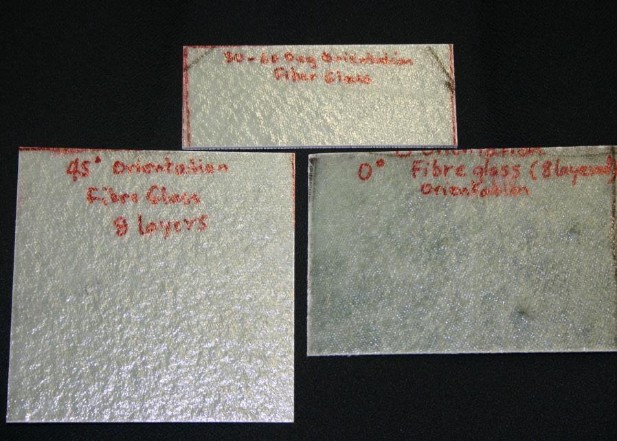
2 Research Objectives: To fabricate fiberglass composite materials of three different fiber orientations - 0 0, 45 0 and To study the Mechanical properties such as Young s Modulus and Poisson s ratio of all samples using Tensile test To calculate the Elastic modulus of these composites using Rule of mixtures To draw the calibration curves for 0 0, 45 0 and oriented fiberglass samples using the sensitive optical fiber loop sensor To compare the results and discuss about the effect of fiber orientation on the mechanical properties of fiberglass composite
3 COMPOSITE MATERIALS * These are prepared by combining two or more different natural or artificial materials to maximize desired properties and also to minimize unwanted properties. Properties: Advantages: Design Objectives: Density Tensile Strength Tensile Modulus Thermal properties Electrical properties High strength Light weight Design Flexibility Strength Toughness Weathering Costs
4 Fiberglass : ( Glass-Reinforced Plastic, GRP ) It is a fiber reinforced polymer made of a plastic matrix ( epoxy ) reinforced by fine fibers of glass. Uses : Boats, Automobiles, Hot tubs, Water tanks, Roofing, Pipes, Advantages: Lightweight, Strong, and Robust material. Low Cost compared to carbon fiber and aramid (Kevlar) Disadvantages: Relatively Low Strength High Elongation Moderate Strength to weight ratio


5 Fabrication: Step 1 : Cutting Step 2 : Lay-up Step 3 : Curing Step 4 : Heating and trimming


6 TENSILE TEST: BONDING STRAIN GAUGE TO THE SAMPLE Basis: Resistance of strain gauge varies with the applied pressure Types of strain gauges: Uniaxial, bixial, delta 3 element, rectangular 3 element

7 TENSILE TEST: In the test circuit, strain gauge will act as one of the resistors in the wheatstone bridge. gives load versus extension data Both tangential and longitudinal voltages are noted down for a point corresponding to linear region of stress strain graph Fig. Sample stressstrain graph Fig. Schematic of wheatstone bridge circuit


8 TENSILE TEST: Fig. Specimen mounted on tensile test machine TENSION TEST SETUP Tension test Strain gauge conditioner 4 channel oscilloscope Data acquisition system Fig. Flow chart of Tension test setup

9 TENSILE TEST RESULTS: Fig. Stress versus strain plots of all fiberglass composite specimens All samples have shown similar behavior with a significant change in the slope of linear region between the range of strain values to The plateau region between the range of strain values to may be due to slip in the grip of clamp fixtures or due to readjustment of matrix particles in between the layers The Young s modulus of each curve is calculated by finding the slope of linear region
10 TENSILE TEST RESULTS: The data of young s modulus values are given below ORIENTATION TRIAL 0 DEGREE (Gpa) 45 DEGREE (Gpa) DEGREE ( Gpa) AVERAGE st dev % st dev Young s modulus of zero degree oriented sample is more than other orientations. A slight variation in young s modulus values between and 45 0 orientations. Results clearly show the effect of orientation on the young s modulus of the fiberglass composite.
11 TENSILE TEST RESULTS: Poisson s ratio = - [ ] Poisson s ratio varies in between 0 and 0.5. Many materials exhibit positive Poisson s ratio Negative Poisson s ratio is exhibited by materials which expand laterally when stretched Ex: Re-entry foam Discovered by Dept. of Materials science, University of Wisconsin Poisson s ratio is calculated using the following formula: Poisson s ratio =
12 TENSILE TEST RESULTS: TABLE: Poisson s ratios of all samples TRIAL 0 DEGREE 45 DEGREE DEGREE AVERAGE STD DEV % STDEV Poisson s ratio of zero degree oriented sample is low compared to other orientations The higher values of Poisson s ratios in and 45 0 orientations may be due to mismatch in the orientation between the layers
13 Rule of mixtures: Fig. Burning and recovery of original fiberglass from composite
14 Rule of mixtures: An analytical method used to calculate the upper limit of modulus of composite. E(composite) = E( fiberglass) V(fiberglass) + E( matrix) V(matrix) Where E : Elastic modulus ; V : volume fraction The volume fractions of constituents- fiberglass and matrix are calculated by burning the composite. The percentage volumes of constituents are shown in the following table. Fiber Orientation Volume of composite cu.mm Volume of fiberglass Cu.mm Volume of epoxy Cu.mm % by volume of fiberglass % by volume of epoxy
15 Rule of mixtures: The elastic modulus value is calculated by using rule of mixtures. ORIENTATIONS E(composite)=E(fiber)xV(fiber)+E(matrix)xV(matrix) = 70 x x = 70 x x = 70 x x 0.39 The Elastic modulus values are well above the Young s modulus values calculated using tensile test
16 Flexural Test: Performed to study the material s ability to withstand the load. The most common flexural test conducted on fiberglass composite materials is the 3-point test. Concave side Convex side Fig.Three point flexural Test

17 Flexural Test: The optical fiber loop is used as a sensor Principle: The intensity of output radiation decreases with a reduction in the diameter of the loop Fig. Optical fiber loop sensor Fig.Composite bonded with optical fiber loop sensor
18 Flexural Test: Fig. Schematic diagram of experimental setup for shear stress test


19 FIBERGLASS Fig. Composite mounted on a platform for 3-point test
20 Flexural Test: Fig. Flexural test calibration curves of 0 0, 45 0 and orientations The results show clear difference in the power output response among different orientations. The output response of zero degree oriented samples is greater compared to other samples.
21 Conclusions: A significant change in the mechanical properties such as Young s modulus and Poisson s ratio have been observed with a change in fiber orientation. The mechanical properties calculated using tensile test are well below the upper limit of elastic modulus values calculated using rule of mixtures. The consistency in the alignment of successive layers plays a key role on the mechanical properties of multilayer composites. A significant difference in the power output response has been observed with fiber orientation. Since, the response of optical fiber output is very sensitive to load, Flexural test using the optical fiber loop is a promising technique to be used in the study of shear modulus.
22 Future work: To check the consistency of the values obtained from each measurement, more samples belonging to the same orientation needs to be fabricated and tested. To study the systematic variation with the fiber orientation, more number of orientations must be tried instead of three. During the fabrication process, extreme care must be taken at each step starting from fiber cutting to heating the composite in the furnace. The effect of fiber orientation in carbon and aramid fiber composites must studied and compared with that of fiberglass. Impact and thermal studies needs to be performed on these samples.

23 LESSON PLAN Topic: Centripetal Force Materials Needed: Basic Stamp2 DC Motor Diode Laser Photodiode Opamp IC - Kevlar string Bob

24 FORMULA F c = ma c = = Where F C : centripetal force ; v: speed of revolving object ; m: mass of the object; a c : centripetal acceleration ; r: length of the string; f: frequency of revolution OBJECTIVES: Distinguish between speed and velocity Differentiate linear and circular motion Relate Newton s second to centripetal force Calculate the centripetal force acting on the object Identify dc motor, basic stamp2 and sensors Understand the working of Basic stamp2 and sensor setup.


25 BLOCK DIAGRAM OF FREQUENCY COUNTER Basic stamp 2 P0 P2 LCD PUSH BUTTON SWITCH SCHMITT TRIGGER PHOTO DIODE

26 SCHMITT TRIGGER High Threshold Level Low Threshold Level Fig. Schmitt trigger circuit and its response A SCHMITT TRIGGER CONVERTS SLOWLY VARRYING NOSY INPUT SIGNAL INTO A RECTANGULAR WAVE
27 High Threshold Level : R TOT = (R1 x R FB ) / (R1 + R FB ) V THRESHOLD_HIGH = V * R2 / (R2 + R TOT ) Low Threshold Level : R TOT = (R2 x R FB ) / (R2 + R FB ) V THRESHOLD_LOW = V x R TOT / (R1 + R TOT )


28 CENTRIPETAL FORCE SETUP


29 CENTRIFUGE : Used to separate substances of different densities. Denser substances tend to be displaced from the center more than ones that are less dense. :
30 Table : Length of the string (Radius ) versus Velocity of the bob Mass of bob(g), m Radius ( m ), r ( length of the string) Time period, T ( s ) Velocity, V V=2πr/T, ( m/s) V 2 ( m/s) Graph: Draw V 2 versus T plot and find the slope of the curve Centripetal force = F c = ma c =
31 Acknowledgements: The following have been instrumental in making this project successful. The timely help, encouragement and guidance rendered by them is commendable. Composite Materials and Mechanics Laboratory Professor Nikhil Gupta - Mentor Mr. Ronald Poveda - Collaborator Mr. Kevin Chen Mr. Gleb Dorogokupets Mr. Petros Skaliarinis Mechatronics Laboratory: Professor Vikram Kapila - Program Dirctor Mr. Jared Frank - Program Insructor Mr. David Lopez - fellow Mr. Xiaoyang Lin - fellow Mr. Alessandro Betti - Machinist National Science Foundation for funding the summer research program Mechanical and Aerospace Engineering Department for organizing the summer research program-2011 and allowing to use their facilities.
32 ' {$STAMP BS2} ' {$PBASIC 2.5} counter VAR Word counter1 VAR Word counter1 = 0 t VAR Byte N VAR Word ' input: numerator ' -6554<N<+6554 D VAR Word ' denominator ' -6554<D<+6554 X VAR Word ' place holder I VAR Word ' integer part J VAR Nib ' index F VAR Word ' fractional part '.0000 to.9999 SEROUT 12, 84, [22, 12] PAUSE 5000 DO DO SEROUT 12, 84, [128, "Press Button..."] LOOP UNTIL (IN0 = 0) FOR t = 1 TO 20 ' number of iterations COUNT 2, 1000, counter ' frequency = t value x counting duration 'DEBUG CLS, HOME,? IN2, CR,? counter counter1 = counter1 + counter 'DEBUG " frequency after",?t, 'DEBUG HOME,? counter1,cr SEROUT 12, 84, [128,"Time= ", DEC2 t, "s, ", "C=", DEC counter1] IF t = 20 THEN N=counter1 D=20 GOSUB Divide SEROUT 12, 84, [148,"Freq = ",DEC I,".",DEC F, "Hz"] PAUSE 500 D=counter1 N=20 GOSUB Divide SEROUT 12, 84, [128,"Period = ",DEC I,".",DEC F, "s"] ENDIF NEXT PAUSE SEROUT 12, 84, [12] counter1 = 0 LOOP divide: I=1-(N.BIT15^D.BIT15*2) ' sign of result N=ABS N ' divide absolute values D=ABS D I=N/D*I ' integer part X=1000 '.1,.01,.001,.0001 place holder F=0 ' fractional part FOR J=1 TO 3 ' 4 places N=N//D*10 ' remainder * 10
ME5643. Mechatronics. Final Project Report. Automated Cantilever Strain Measurements. Group 8. Francisco Gilbert Kitty Lamb
 ME5643 Mechatronics Final Project Report Automated Cantilever Strain Measurements Group 8 Francisco Gilbert Kitty Lamb December 21 st, 2009 Tables of contents 1. Abstract 2. Introduction 3. System a. Mechanical
Bending Load & Calibration Module
 Bending Load & Calibration Module Objectives After completing this module, students shall be able to: 1) Conduct laboratory work to validate beam bending stress equations. 2) Develop an understanding of
Laboratory 7 Measurement on Strain & Force. Department of Mechanical and Aerospace Engineering University of California, San Diego MAE170
 Laboratory 7 Measurement on Strain & Force Department of Mechanical and Aerospace Engineering University of California, San Diego MAE170 Megan Ong Diana Wu Wong B01 Tuesday 11am May 17 th, 2015 Abstract:
Strain Measurement. Prof. Yu Qiao. Department of Structural Engineering, UCSD. Strain Measurement
 Strain Measurement Prof. Yu Qiao Department of Structural Engineering, UCSD Strain Measurement The design of load-carrying components for machines and structures requires information about the distribution
Experiment Five (5) Principal of Stress and Strain
 Principal of Stress and Strain") Experiment Five (5) Principal of Stress and Strain Introduction Objective: To determine principal stresses and strains in a beam made of aluminum and loaded as a cantilever, and compare them with theoretical
Experiment Five (5) Principal of Stress and Strain Introduction Objective: To determine principal stresses and strains in a beam made of aluminum and loaded as a cantilever, and compare them with theoretical
What is a Strain Gauge? Strain Gauge. Schematic View Of Strain Gauge
 ( ) : 1391-92 92 What is Strain? Strain is the amount of deformation of a body due to an applied force. More specifically, strain (ε) is defined as the fractional change in length. Strain can be positive
Chapter 7. Highlights:
 Chapter 7 Highlights: 1. Understand the basic concepts of engineering stress and strain, yield strength, tensile strength, Young's(elastic) modulus, ductility, toughness, resilience, true stress and true
M E F I N A L P R O J E C T
 M E 5 6 4 3 F I N A L P R O J E C T DENSITY METER Shing Lik Wong, Yi Hu, Jasmin Hume December 2011 ABSTRACT The density of matter is defined as the ratio of mass to volume. We have constructed an instrument
ENSC387: Introduction to Electromechanical Sensors and Actuators LAB 3: USING STRAIN GAUGES TO FIND POISSON S RATIO AND YOUNG S MODULUS
 ENSC387: Introduction to Electromechanical Sensors and Actuators LAB 3: USING STRAIN GAUGES TO FIND POISSON S RATIO AND YOUNG S MODULUS 1 Introduction... 3 2 Objective... 3 3 Supplies... 3 4 Theory...
Task 1 - Material Testing of Bionax Pipe and Joints
 Task 1 - Material Testing of Bionax Pipe and Joints Submitted to: Jeff Phillips Western Regional Engineer IPEX Management, Inc. 20460 Duncan Way Langley, BC, Canada V3A 7A3 Ph: 604-534-8631 Fax: 604-534-7616
FALLING OBJECTS. Edna T. Diolata Brooklyn Technical High School. and. David Latman Clara Barton High School For The Health Professions
 FALLING OBJECTS by Edna T. Diolata Brooklyn Technical High School and David Latman Clara Barton High School For The Health Professions INTRODUCTION A simple experiment on falling bodies such as the one
Mechatronics II Laboratory EXPERIMENT #1: FORCE AND TORQUE SENSORS DC Motor Characteristics Dynamometer, Part I
 Mechatronics II Laboratory EXPEIMENT #1: FOCE AND TOQUE SENSOS DC Motor Characteristics Dynamometer, Part I Force Sensors Force and torque are not measured directly. Typically, the deformation or strain
International Journal of Scientific & Engineering Research, Volume 5, Issue 1, January ISSN
 International Journal of Scientific & Engineering Research, Volume 5, Issue 1, January-214 29 An Experimental Analysis of Stress Relaxation in Nonwoven Fabrics Sajid Ahmed Qureshi ABSTRACT - The current
MET 487 Instrumentation and Automatic Controls. Lecture 13 Sensors
 MET 87 nstrumentation and utomatic Controls Lecture Sensors July 6-9, 00 Stress and Strain Measurement Safe Load Level monitoring Force (indirect measurement by measuring strain of a flexural element Pressure
CLASSIFIATION of ONE-DIMENSIONAL COLLISION
 GROUP 1 Lennon Safe Carol Obler SMART PROJECT PROJECT PAPER: Introduction: According to Newton's experimental law, for a given pair of bodies in collision, the ratio of final relative speed to initial
Elasticity: Term Paper. Danielle Harper. University of Central Florida
 Elasticity: Term Paper Danielle Harper University of Central Florida I. Abstract This research was conducted in order to experimentally test certain components of the theory of elasticity. The theory was
Lab Exercise #5: Tension and Bending with Strain Gages
 Lab Exercise #5: Tension and Bending with Strain Gages Pre-lab assignment: Yes No Goals: 1. To evaluate tension and bending stress models and Hooke s Law. a. σ = Mc/I and σ = P/A 2. To determine material
Stress-Strain Behavior
 Stress-Strain Behavior 6.3 A specimen of aluminum having a rectangular cross section 10 mm 1.7 mm (0.4 in. 0.5 in.) is pulled in tension with 35,500 N (8000 lb f ) force, producing only elastic deformation.
Enhancement of buckling load of thin plates using Piezoelectric actuators
 Enhancement of buckling load of thin plates using Piezoelectric actuators R. Indira Priyadarshini a, C.Lakshmana Rao b, S.M.Siva Kumar b a) Master of Science by Research Student, Department of Applied
AE3610 Experiments in Fluid and Solid Mechanics TRANSIENT MEASUREMENTS OF HOOP STRESSES FOR A THIN-WALL PRESSURE VESSEL
 Objective AE3610 Experiments in Fluid and Solid Mechanics TRANSIENT MEASUREMENTS OF OOP STRESSES FOR A TIN-WA PRESSURE VESSE This experiment will allow you to investigate hoop and axial stress/strain relations
Elastic Properties of Solids Exercises I II for one weight Exercises III and IV give the second weight
 Elastic properties of solids Page 1 of 8 Elastic Properties of Solids Exercises I II for one weight Exercises III and IV give the second weight This is a rare experiment where you will get points for breaking
Mechatronics II Laboratory EXPERIMENT #1 MOTOR CHARACTERISTICS FORCE/TORQUE SENSORS AND DYNAMOMETER PART 1
 Mechatronics II Laboratory EXPEIMENT #1 MOTO CHAACTEISTICS FOCE/TOQUE SENSOS AND DYNAMOMETE PAT 1 Force Sensors Force and torque are not measured directly. Typically, the deformation or strain of some
1.105 Solid Mechanics Laboratory Fall 2003 Experiment 3 The Tension Test
 1.105 Solid Mechanics Laboratory Fall 2003 Experiment 3 The Tension Test Our objective is to measure the Elastic Modulus of steel. The experiment comes in two parts. In the first, you will subject a steel
Peak Strain and Displacement Sensors for Structural Health Monitoring
 Peak Strain and Displacement Sensors for Structural Health Monitoring AKIRA MITA and SHINPEI TAKAHIRA ABSTRACT Simple and inexpensive passive sensors that can monitor the peak strain or displacement of
Wilberforce Pendulum (One or two weights)
") Wilberforce Pendulum (One or two weights) For a 1 weight experiment do Part 1 (a) and (b). For a weight experiment do Part1 and Part Recommended readings: 1. PHY15 University of Toronto. Selected Material
Wilberforce Pendulum (One or two weights) For a 1 weight experiment do Part 1 (a) and (b). For a weight experiment do Part1 and Part Recommended readings: 1. PHY15 University of Toronto. Selected Material
STANDARD SAMPLE. Reduced section " Diameter. Diameter. 2" Gauge length. Radius
 MATERIAL PROPERTIES TENSILE MEASUREMENT F l l 0 A 0 F STANDARD SAMPLE Reduced section 2 " 1 4 0.505" Diameter 3 4 " Diameter 2" Gauge length 3 8 " Radius TYPICAL APPARATUS Load cell Extensometer Specimen
Elastic Properties of Solids (One or two weights)
") Elastic properties of solids Page 1 of 8 Elastic Properties of Solids (One or two weights) This is a rare experiment where you will get points for breaking a sample! The recommended textbooks and other
Elastic properties of solids Page 1 of 8 Elastic Properties of Solids (One or two weights) This is a rare experiment where you will get points for breaking a sample! The recommended textbooks and other
Force and Displacement Measurement
 Force and Displacement Measurement Prof. R.G. Longoria Updated Fall 20 Simple ways to measure a force http://scienceblogs.com/dotphysics/200/02/diy_force_probe.php Example: Key Force/Deflection measure
Industrial Instrumentation Dr. Alok Barua Department of Electrical Engineering Indian Institute of Technology Kharagpur. Lecture - 4 Strain Gauge
 Industrial Instrumentation Dr. Alok Barua Department of Electrical Engineering Indian Institute of Technology Kharagpur Lecture - 4 Strain Gauge Welcome to the lesson 4 of industrial instrumentation. In
Lecture 19. Measurement of Solid-Mechanical Quantities (Chapter 8) Measuring Strain Measuring Displacement Measuring Linear Velocity
 Measuring Strain Measuring Displacement Measuring Linear Velocity") MECH 373 Instrumentation and Measurements Lecture 19 Measurement of Solid-Mechanical Quantities (Chapter 8) Measuring Strain Measuring Displacement Measuring Linear Velocity Measuring Accepleration and
MECH 373 Instrumentation and Measurements Lecture 19 Measurement of Solid-Mechanical Quantities (Chapter 8) Measuring Strain Measuring Displacement Measuring Linear Velocity Measuring Accepleration and
Experiment Two (2) Torsional testing of Circular Shafts
 Torsional testing of Circular Shafts") Experiment Two (2) Torsional testing of Circular Shafts Introduction: Torsion occurs when any shaft is subjected to a torque. This is true whether the shaft is rotating (such as drive shafts on engines,
Experiment Two (2) Torsional testing of Circular Shafts Introduction: Torsion occurs when any shaft is subjected to a torque. This is true whether the shaft is rotating (such as drive shafts on engines,
CHAPTER 6 FRICTION AND WEAR ANALYSIS FOR BUSHING
 CHAPTER 6 FRICTION AND WEAR ANALYSIS FOR BUSHING 6.1 TEST RIG SETUP FOR THE FRICTION AND WEAR ANALYSIS Knowing the frictional coefficient is important for the determination of wear loss and power loss
PANDIAN SARASWATHI YADAV ENGINEERING COLLEGE DEPARTMENT OF ELECTRICAL AND ELECTRONICS ENGINEERING EE6404-MEASUREMENTS AND INSTRUMENTATION
 PANDIAN SARASWATHI YADAV ENGINEERING COLLEGE DEPARTMENT OF ELECTRICAL AND ELECTRONICS ENGINEERING EE6404-MEASUREMENTS AND INSTRUMENTATION ACADEMIC YEAR: 2015-2016 (EVEN SEMESTER) Branch: EEE QUESTION BANK
The objective of this experiment is to investigate the behavior of steel specimen under a tensile test and to determine it's properties.
 Objective: The objective of this experiment is to investigate the behavior of steel specimen under a tensile test and to determine it's properties. Introduction: Mechanical testing plays an important role
Experimental Approach to Determine the Stress at a Section of Semi Circular Curved Beam Subjected to Out-Of-Plane Load Using Strain Rosette
 Experimental Approach to Determine the Stress at a Section of Semi Circular Curved Beam Subjected to Out-Of-Plane Load Using Strain Rosette Rakshith N 1, Dr. D S Ramakrishna 2, Srinivasa K 3, Md Nadeem
Circular Motion and Centripetal Force
 [For International Campus Lab ONLY] Objective Measure the centripetal force with the radius, mass, and speed of a particle in uniform circular motion. Theory ----------------------------- Reference --------------------------
Module III - Macro-mechanics of Lamina. Lecture 23. Macro-Mechanics of Lamina
 Module III - Macro-mechanics of Lamina Lecture 23 Macro-Mechanics of Lamina For better understanding of the macromechanics of lamina, the knowledge of the material properties in essential. Therefore, the
PHYS221 Experiment 7 - Centripetal Force
 Experiment 7 - Centripetal Force Spring Tension Setting Bob Apparatus Variable Speed Control Automatic Counter Fig. 7-1 Centripetal Force Apparatus. Note: NO HANGER when upright! Fig. 7-2 Centripetal Force
STRAIN GAUGES YEDITEPE UNIVERSITY DEPARTMENT OF MECHANICAL ENGINEERING
 STRAIN GAUGES YEDITEPE UNIVERSITY DEPARTMENT OF MECHANICAL ENGINEERING 1 YEDITEPE UNIVERSITY ENGINEERING FACULTY MECHANICAL ENGINEERING LABORATORY 1. Objective: Strain Gauges Know how the change in resistance
Strain Gages. Approximate Elastic Constants (from University Physics, Sears Zemansky, and Young, Reading, MA, 1979
 Material Strain Gages Approximate Elastic Constants (from University Physics, Sears Zemansky, and Young, Reading, MA, 1979 Young's Modulus, Y Shear Modulus, S Bulk Modulus, B Poisson's Ratio 10 11 N/m
Calibration and Experimental Validation of LS-DYNA Composite Material Models by Multi Objective Optimization Techniques
 9 th International LS-DYNA Users Conference Optimization Calibration and Experimental Validation of LS-DYNA Composite Material Models by Multi Objective Optimization Techniques Stefano Magistrali*, Marco
PHYSICS. Unit 3 Written examination Trial Examination SOLUTIONS
 PHYSICS Unit 3 Written examination 1 2012 Trial Examination SECTION A Core Motion in one and two dimensions Question 1 SOLUTIONS Answer: 120 N Figure 1 shows that at t = 5 sec, the cart is travelling with
AERO 214. Lab II. Measurement of elastic moduli using bending of beams and torsion of bars
 AERO 214 Lab II. Measurement of elastic moduli using bending of beams and torsion of bars BENDING EXPERIMENT Introduction Flexural properties of materials are of interest to engineers in many different
GB/T / ISO 527-1:1993
 Translated English of Chinese Standard: GB/T1040.1-2006 www.chinesestandard.net Sales@ChineseStandard.net GB NATIONAL STANDARD OF THE PEOPLE S REPUBLIC OF CHINA ICS 83.080.01 G 31 GB/T 1040.1-2006 / ISO
Structures - Experiment 3B Sophomore Design - Fall 2006
 Structures - Experiment 3B 1.101 Sophomore Design - Fall 2006 Linear elastic behavior of a beam. The objectives of this experiment are to experimentally study the linear elastic behavior of beams under
1. Mark the correct statement(s)
") 1. Mark the correct statement(s) Figure to the right shows a mass measurement scale using a spring. 1.1 The span of the scale is a) 16 kg b) 21 kg c) 11 kg d) 5-16 kg 1.2 The range of the scale is a) 16
1. Mark the correct statement(s) Figure to the right shows a mass measurement scale using a spring. 1.1 The span of the scale is a) 16 kg b) 21 kg c) 11 kg d) 5-16 kg 1.2 The range of the scale is a) 16
Strain Gages. Approximate Elastic Constants (from University Physics, Sears Zemansky, and Young, Reading, MA, Shear Modulus, (S) N/m 2
 N/m 2") When you bend a piece of metal, the Strain Gages Approximate Elastic Constants (from University Physics, Sears Zemansky, and Young, Reading, MA, 1979 Material Young's Modulus, (E) 10 11 N/m 2 Shear Modulus,
When you bend a piece of metal, the Strain Gages Approximate Elastic Constants (from University Physics, Sears Zemansky, and Young, Reading, MA, 1979 Material Young's Modulus, (E) 10 11 N/m 2 Shear Modulus,
Tensile stress strain curves for different materials. Shows in figure below
 Tensile stress strain curves for different materials. Shows in figure below Furthermore, the modulus of elasticity of several materials effected by increasing temperature, as is shown in Figure Asst. Lecturer
[5] Stress and Strain
![[5] Stress and Strain](/thumbs/95/123344550.jpg "[5] Stress and Strain") [5] Stress and Strain Page 1 of 34 [5] Stress and Strain [5.1] Internal Stress of Solids [5.2] Design of Simple Connections (will not be covered in class) [5.3] Deformation and Strain [5.4] Hooke s Law
[5] Stress and Strain Page 1 of 34 [5] Stress and Strain [5.1] Internal Stress of Solids [5.2] Design of Simple Connections (will not be covered in class) [5.3] Deformation and Strain [5.4] Hooke s Law
CHEM-C2410: Materials Science from Microstructures to Properties Composites: basic principles
 CHEM-C2410: Materials Science from Microstructures to Properties Composites: basic principles Mark Hughes 14 th March 2017 Today s learning outcomes To understand the role of reinforcement, matrix and
MCE 403 MACHINERY LABORATORY EXPERIMENT 10
 1 1.OBJECTIVE The objective of this experiment is to become familiar with the electric resistance strain gauge techniques and utilize such gauges for the determination of unknown quantities (such as strain,
INTRODUCTION TO STRAIN
 SIMPLE STRAIN INTRODUCTION TO STRAIN In general terms, Strain is a geometric quantity that measures the deformation of a body. There are two types of strain: normal strain: characterizes dimensional changes,
I. MEASUREMENT OF TEMPERATURE
 I. MEASUREMENT OF TEMPERATURE Most frequent measurement and control Direct contact: thermometer, Indirect contact: pyrometer (detect generated heat or sensing optical properties) 1. Definition of temperature
Strain Measurement MEASUREMENT EXPERIMENT
 Strain Measurement MEASUREMENT EXPERIMENT 1. OBJECT The objective of this experiment is to become familiar with the electric resistance strain gage techniques and utilize such gages for the determination
Difference Between Fixed and Floating Reference Points AASHTO T-321
 Difference Between Fixed and Floating Reference Points AASHTO T-321 Fixed Reference LVDT with Target Attached to the Beam Neutral Axis (Mid-Height, Mid-Length) 2 Old ASTM D7460 Graph Improper Representation
Single fibre tensile testing
 Single fibre tensile testing Justine Beauson Section of Composites and Materials Mechanics, Department of Wind Energy Introduction Fibre properties Fibre orientation Matrix properties Mechanical performance
ME 243. Mechanics of Solids
 ME 243 Mechanics of Solids Lecture 2: Stress and Strain Ahmad Shahedi Shakil Lecturer, Dept. of Mechanical Engg, BUET E-mail: sshakil@me.buet.ac.bd, shakil6791@gmail.com Website: teacher.buet.ac.bd/sshakil
III B.Tech. II Semester Regular Examinations, April/May INSTRUMENTATION & CONTROL SYSTEMS (Mechanical Engineering) Time: 3 Hours Max Marks: 75
 Time: 3 Hours Max Marks: 75") R10 Set No: 1 1. (a) Distinguish between accuracy and Precision. Which of these is more desirable during the act of measurement and why? (b) Discuss the necessity and importance of dynamic performance
R10 Set No: 1 1. (a) Distinguish between accuracy and Precision. Which of these is more desirable during the act of measurement and why? (b) Discuss the necessity and importance of dynamic performance
MSC Elastomers Seminar Some Things About Elastomers
 MSC Elastomers Seminar Some Things About Elastomers Kurt Miller, Axel Products, Inc. www.axelproducts.com Visit us at: axelproducts.com 2 Your Presenter Kurt Miller Founded Axel Products 1994 Instron Corporation,
Material Characterization of Carbon Fiber Reinforced Polymer Laminate Using Virtual Fields Method
 Proceedings of ICTACEM 014 International Conference on Theoretical, Applied, Computational and Experimental Mechanics December 9-31, 014, IIT Kharagpur, India ICTACEM-014/39 Material Characterization of
Strain Gauge Application and Measurement of Unknown Load
 University Diploma Program Electronic Equipment Maintenance Lab Instructor: Muhammad Ajmal Khan EET-027, Experiment # 6 Strain Gauge Application and Measurement of Unknown Load Objectives: 1. To find the
MAS.836 PROBLEM SET THREE
 MAS.836 PROBLEM SET THREE FSR, Strain Gauge, and Piezo Circuits: The purpose of this problem set is to familiarize yourself with the most common forms of pressure and force measurement. The circuits you
Purpose of this Guide: To thoroughly prepare students for the exact types of problems that will be on Exam 3.
 ES230 STRENGTH OF MTERILS Exam 3 Study Guide Exam 3: Wednesday, March 8 th in-class Updated 3/3/17 Purpose of this Guide: To thoroughly prepare students for the exact types of problems that will be on
Lab Exercise #3: Torsion
 Lab Exercise #3: Pre-lab assignment: Yes No Goals: 1. To evaluate the equations of angular displacement, shear stress, and shear strain for a shaft undergoing torsional stress. Principles: testing of round
Wilberforce Pendulum (One or two weights)
") Wilberforce Pendulum (One or two weights) For a 1 weight experiment do Part 1 (a) and (b). For a 2 weight experiment do Part1 and Part 2 Recommended readings: 1. R.A.Serway and J.W.Jewett, Jr. Physics
Wilberforce Pendulum (One or two weights) For a 1 weight experiment do Part 1 (a) and (b). For a 2 weight experiment do Part1 and Part 2 Recommended readings: 1. R.A.Serway and J.W.Jewett, Jr. Physics
Prediction of Elastic Constants on 3D Four-directional Braided
 Prediction of Elastic Constants on 3D Four-directional Braided Composites Prediction of Elastic Constants on 3D Four-directional Braided Composites Liang Dao Zhou 1,2,* and Zhuo Zhuang 1 1 School of Aerospace,
Exercise: concepts from chapter 8
 Reading: Fundamentals of Structural Geology, Ch 8 1) The following exercises explore elementary concepts associated with a linear elastic material that is isotropic and homogeneous with respect to elastic
Prediction of Micromechanical Behaviour of Elliptical Frp Composites
 Prediction of Micromechanical Behaviour of Elliptical Frp Composites Kiranmayee.Nerusu Dept. of Mechanical Engg. P. V. P. Siddhartha Institute of Technology, Vijayawada 520 007, A.P, India. P. Phani Prasanthi
Mechanical properties 1 Elastic behaviour of materials
 MME131: Lecture 13 Mechanical properties 1 Elastic behaviour of materials A. K. M. B. Rashid Professor, Department of MME BUET, Dhaka Today s Topics Deformation of material under the action of a mechanical
Mechanical Behavior of Circular Composite Springs with Extended Flat Contact Surfaces
 Mechanical Behavior of Circular Composite Springs with Extended Flat Contact Surfaces Ping-Cheung Tse epartment of Mechanical Engineering, The Hong Kong Polytechnic University, Hunghom, Kowloon, Hong Kong
Design of a fastener based on negative Poisson's ratio foam adapted from
 1 Design of a fastener based on negative Poisson's ratio foam adapted from Choi, J. B. and Lakes, R. S., "Design of a fastener based on negative Poisson's ratio foam", Cellular Polymers, 10, 205-212 (1991).
UNIT I SIMPLE STRESSES AND STRAINS
 Subject with Code : SM-1(15A01303) Year & Sem: II-B.Tech & I-Sem SIDDHARTH GROUP OF INSTITUTIONS :: PUTTUR Siddharth Nagar, Narayanavanam Road 517583 QUESTION BANK (DESCRIPTIVE) UNIT I SIMPLE STRESSES
Structural Metals Lab 1.2. Torsion Testing of Structural Metals. Standards ASTM E143: Shear Modulus at Room Temperature
 Torsion Testing of Structural Metals Standards ASTM E143: Shear Modulus at Room Temperature Purpose To determine the shear modulus of structural metals Equipment Tinius-Olsen Lo-Torq Torsion Machine (figure
3 Hours/100 Marks Seat No.
 *17304* 17304 14115 3 Hours/100 Marks Seat No. Instructions : (1) All questions are compulsory. (2) Illustrate your answers with neat sketches wherever necessary. (3) Figures to the right indicate full
2. (a) Differentiate between rare metal thermocouples and base metal thermocouples.
 Differentiate between rare metal thermocouples and base metal thermocouples.") Code No: R05410304 Set No. 1 1. (a) Distinguish between direct and indirect methods of measurement with suitable examples. (b) What are desired, modifying and interfering inputs for an instrumentation
Code No: R05410304 Set No. 1 1. (a) Distinguish between direct and indirect methods of measurement with suitable examples. (b) What are desired, modifying and interfering inputs for an instrumentation
High Temperature Strain Measurements Using Fiber Optic Sensors
 High Temperature Strain Measurements Using Fiber Optic Sensors Paul J. Gloeckner, Ph.D. Cummins, Inc. 1900 McKinley Ave. Columbus, IN 47201 ABSTRACT Strain gage measurements at elevated temperatures (>
ME411 Engineering Measurement & Instrumentation. Winter 2017 Lecture 9
 ME411 Engineering Measurement & Instrumentation Winter 2017 Lecture 9 1 Introduction If we design a load bearing component, how do we know it will not fail? Simulate/predict behavior from known fundamentals
AC-829A. Issued on Apr. 15 th 2013 (Version 1.0)
") Hitachi Chemical Co., Ltd. Hitachi Anisotropic Conductive Film ANISOLM AC-829A Issued on Apr. 15 th 2013 (Version 1.0) 1. Standard specification, bonding condition, storage condition and characteristic.....1
Hitachi Chemical Co., Ltd. Hitachi Anisotropic Conductive Film ANISOLM AC-829A Issued on Apr. 15 th 2013 (Version 1.0) 1. Standard specification, bonding condition, storage condition and characteristic.....1
Micromechanical analysis of FRP hybrid composite lamina for in-plane transverse loading
 Indian Journal of Engineering & Materials Sciences Vol. 15, October 2008, pp. 382-390 Micromechanical analysis of FRP hybrid composite lamina for in-plane transverse loading K Sivaji Babu a *, K Mohana
6.4 A cylindrical specimen of a titanium alloy having an elastic modulus of 107 GPa ( psi) and
 and") 6.4 A cylindrical specimen of a titanium alloy having an elastic modulus of 107 GPa (15.5 10 6 psi) and an original diameter of 3.8 mm (0.15 in.) will experience only elastic deformation when a tensile
6.4 A cylindrical specimen of a titanium alloy having an elastic modulus of 107 GPa (15.5 10 6 psi) and an original diameter of 3.8 mm (0.15 in.) will experience only elastic deformation when a tensile
 Set No. 1 1. (a) Differentiate among Desired, Modifying and Interfering inputs. (b) How do you eliminate the effects of interfering and modifying inputs? Explain 2. (a) Define the term Transducer and explain
A RESEARCH ON NONLINEAR STABILITY AND FAILURE OF THIN- WALLED COMPOSITE COLUMNS WITH OPEN CROSS-SECTION
 A RESEARCH ON NONLINEAR STABILITY AND FAILURE OF THIN- WALLED COMPOSITE COLUMNS WITH OPEN CROSS-SECTION H. Debski a*, J. Bienias b, P. Jakubczak b a Faculty of Mechanical Engineering, Department of Machine
Design and Development of Impact Load Sensor for Dynamic Testing Purposes
 IOP Conference Series: Materials Science and Engineering PAPER OPEN ACCESS Design and Development of Impact Load Sensor for Dynamic Testing Purposes To cite this article: E Permana and Yayat 2018 IOP Conf.
Passive Damping Characteristics of Carbon Epoxy Composite Plates
 Journal of Materials Science and Engineering A 6 (-) 35-4 doi:.765/6-63/6.-.5 D DAVID PUBLISHING Passive Damping Characteristics of Carbon Epoxy Composite Plates Dileep Kumar K * and V V Subba Rao Faculty
BIAXIAL STRENGTH INVESTIGATION OF CFRP COMPOSITE LAMINATES BY USING CRUCIFORM SPECIMENS
 BIAXIAL STRENGTH INVESTIGATION OF CFRP COMPOSITE LAMINATES BY USING CRUCIFORM SPECIMENS H. Kumazawa and T. Takatoya Airframes and Structures Group, Japan Aerospace Exploration Agency 6-13-1, Ohsawa, Mitaka,
CE 320 Structures Laboratory 1 Flexure Fall 2006
 CE 320 Structures Laboratory 1 Flexure Fall 2006 General Note: All structures labs are to be conducted by teams of no more than four students. Teams are expected to meet to decide on an experimental design
Computational Analysis for Composites
 Computational Analysis for Composites Professor Johann Sienz and Dr. Tony Murmu Swansea University July, 011 The topics covered include: OUTLINE Overview of composites and their applications Micromechanics
Samantha Ramirez, MSE. Stress. The intensity of the internal force acting on a specific plane (area) passing through a point. F 2
 passing through a point. F 2") Samantha Ramirez, MSE Stress The intensity of the internal force acting on a specific plane (area) passing through a point. Δ ΔA Δ z Δ 1 2 ΔA Δ x Δ y ΔA is an infinitesimal size area with a uniform force
Samantha Ramirez, MSE Stress The intensity of the internal force acting on a specific plane (area) passing through a point. Δ ΔA Δ z Δ 1 2 ΔA Δ x Δ y ΔA is an infinitesimal size area with a uniform force
BioMechanics and BioMaterials Lab (BME 541) Experiment #5 Mechanical Prosperities of Biomaterials Tensile Test
 Experiment #5 Mechanical Prosperities of Biomaterials Tensile Test") BioMechanics and BioMaterials Lab (BME 541) Experiment #5 Mechanical Prosperities of Biomaterials Tensile Test Objectives 1. To be familiar with the material testing machine(810le4) and provide a practical
BioMechanics and BioMaterials Lab (BME 541) Experiment #5 Mechanical Prosperities of Biomaterials Tensile Test Objectives 1. To be familiar with the material testing machine(810le4) and provide a practical
Effect of Thickness and Fiber Orientation on Flexural Strength of GFRP Composites
 Effect of Thickness and Fiber Orientation on Flexural Strength of GFRP Composites Mahesh Chandrashekhar Swamy 1, Parmeshwar Patil 2, Shivaji D. Chame 3, 1 Associate Prof., Dept. of Mechanical Engg., M.S.Bidve
Activity Tensile Testing SIM
 Activity 2.3.2 Tensile Testing SIM Introduction Tensile testing provides engineers with the ability to verify and establish material properties related to a specific material. This verification process
Experiment P13: Atwood's Machine (Smart Pulley)
") PASCO scientific Physics Lab Manual: P13-1 Experiment P13: Atwood's Machine (Smart Pulley) Concept Time SW Interface Macintosh file Windows file Newton's Laws 45 m 500 or 700 P13 Atwood's Machine P13_ATWD.SWS
PASCO scientific Physics Lab Manual: P13-1 Experiment P13: Atwood's Machine (Smart Pulley) Concept Time SW Interface Macintosh file Windows file Newton's Laws 45 m 500 or 700 P13 Atwood's Machine P13_ATWD.SWS
CIVIL DEPARTMENT MECHANICS OF STRUCTURES- ASSIGNMENT NO 1. Brach: CE YEAR:
 MECHANICS OF STRUCTURES- ASSIGNMENT NO 1 SEMESTER: V 1) Find the least moment of Inertia about the centroidal axes X-X and Y-Y of an unequal angle section 125 mm 75 mm 10 mm as shown in figure 2) Determine
Massachusetts Institute of Technology Department of Aeronautics and Astronautics Cambridge, MA Problem Set 14
 Massachusetts Institute of Technology Department of Aeronautics and Astronautics Cambridge, MA 02139 16.01/16.02 Unified Engineering I, II Fall 2003 Problem Set 14 Name: Due Date: 12/9/03 F18 F19 F20 M19
Exercise 2: Bending Beam Load Cell
 Transducer Fundamentals The Strain Gauge Exercise 2: Bending Beam Load Cell EXERCISE OBJECTIVE When you have completed this exercise, you will be able to explain and demonstrate the operation of a board,
Title of Lesson: Can All Things Stretch? RET Project Connection: Failure Modes of Lightweight Sandwich Structures
 Title of Lesson: Can All Things Stretch? RET Project Connection: Failure Modes of Lightweight Sandwich Structures RET Teacher: Michael Wall School: Andover High School Town/District: Andover Public Schools
CIVL222 STRENGTH OF MATERIALS. Chapter 6. Torsion
 CIVL222 STRENGTH OF MATERIALS Chapter 6 Torsion Definition Torque is a moment that tends to twist a member about its longitudinal axis. Slender members subjected to a twisting load are said to be in torsion.
Failure analysis of serial pinned joints in composite materials
 Indian Journal of Engineering & Materials Sciences Vol. 18, April 2011, pp. 102-110 Failure analysis of serial pinned joints in composite materials Alaattin Aktaş* Department of Mechanical Engineering,
A coupled field finite element model to predict actuation properties of piezoelectrically actuated bistable composites.
 A coupled field finite element model to predict actuation properties of piezoelectrically actuated bistable composites. P.F.Giddings, C.R.Bowen, H.A.Kim University of Bath, UK Dept. Mech. ng, University
1.103 CIVIL ENGINEERING MATERIALS LABORATORY (1-2-3) Dr. J.T. Germaine Spring 2004 LABORATORY ASSIGNMENT NUMBER 6
 Dr. J.T. Germaine Spring 2004 LABORATORY ASSIGNMENT NUMBER 6") 1.103 CIVIL ENGINEERING MATERIALS LABORATORY (1-2-3) Dr. J.T. Germaine MIT Spring 2004 LABORATORY ASSIGNMENT NUMBER 6 COMPRESSION TESTING AND ANISOTROPY OF WOOD Purpose: Reading: During this laboratory
1.103 CIVIL ENGINEERING MATERIALS LABORATORY (1-2-3) Dr. J.T. Germaine MIT Spring 2004 LABORATORY ASSIGNMENT NUMBER 6 COMPRESSION TESTING AND ANISOTROPY OF WOOD Purpose: Reading: During this laboratory