Moldflow Report Beaumont Logo. Performed by: Beaumont Technologies Requested by: Customer
|
|
|
- Derick Holmes
- 5 years ago
- Views:
Transcription

1 Moldflow Report Beaumont Logo Performed by: Beaumont Technologies Requested by: Customer
2 Objective To analyze the BTI Logo part in order to determine an optimal gate location. To thoroughly evaluate the filling progression in an attempt to discover any potential molding concerns. To detail warpage based upon cooling line placement, volumetric shrinkage, and fiber orientation effects.
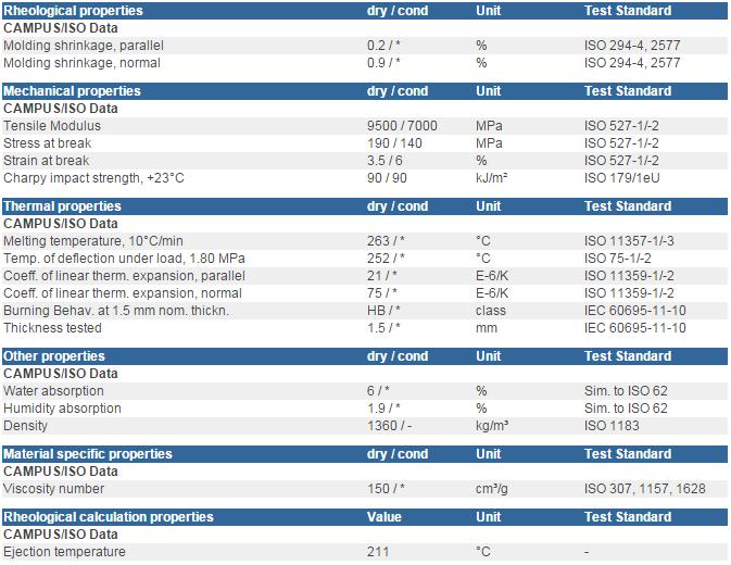
3 Process Set-up for Analysis The following parameters were used to run the analysis: Material: Zytel PLS90G30DR BK099: PA66, DuPont Performance Polymers [30% Glass Fiber Filled] Melt Temperature = 554 F Water Temperature = 190 F Injection time = seconds based on DOE study V/P Switchover = 98% Full Part Pack Profile = 8,000 psi until gate seal

4 Dimensional Diagnostics Part wall thickness =
5 Material Information

6 Gate Locations - Center Gate - End Gate

7 Analysis Set-Up (Center Gate) Tab Gate: X Ø Sprue: Inlet = Ø Standard 1.2 Taper Length = 2.5

8 Analysis Set-Up (End Gate) Tab Gate: X Sprue: Inlet = Ø Standard 1.2 Taper Length = 2.5 Ø Ø 0.156
9 Injection Time- DOE Results, Center Gate A DOE study was run to evaluate the effect of injection time on pressure and flow front temperature distribution. This gives an indication of the overall processing window and preferred fill time.
10 Injection Time- DOE Results, End Gate A DOE study was run to evaluate the effect of injection time on pressure and flow front temperature distribution. This gives an indication of the overall processing window and preferred fill time.

11 Injection Time DOE Comparison Results

12 Fill Time The mold was filled using an injection time of seconds. The black lines represent the location of the weld lines.
13 Filling Progression The Fill time result shows the position of the flow front at regular intervals as the cavity fills. The result is dark blue at the start of the injection, and the last areas to fill are red.

14 Filling Progression Slight hesitation through thin regions Air Trap
15 Filling Progression Weld Line Slight hesitation through thin regions

16 Filling Progression Slight hesitation through thin regions

17 Filling Progression Weld Line Air Trap Slight hesitation through thin regions
18 Filling Progression Weld Line Weld Line Slight race tracking effect due to thicker rim geometry Slight hesitation through thin regions

19 Filling Progression Weld Line Slight race tracking effect due to thicker rim geometry Slight hesitation through thin regions
20 Filling Progression Weld Line Air Trap Air Trap Weld Line Air Trap Slight hesitation through thin regions
21 Filling Progression Hesitation Weld Line Weld Line Air Trap Slight hesitation through thin regions
22 Filling Progression Hesitation Weld Line Weld Line Weld Line Slight hesitation through thin regions
23 Filling Progression Hesitation Weld Line Weld Line Weld Line/ Air Trap Slight hesitation through thin regions
24 Filling Progression Slight race tracking effect due to thicker rim geometry Weld Line Weld Line Slight hesitation through thin regions

25 Filling Progression Weld Lines/ Air Traps Weld Line/ Air Trap Slight race tracking effect due to thicker rim geometry
26 Filling Progression 98% Full V/P Switchover Air Trap End of Fill Weld Line End of Fill Weld Line Slight race tracking effect due to thicker rim geometry
, narrow contours indicate hesitation. shows a higher degree of hesitation throughout the part compared to.")
27 Filling Progression This plot shows the filling progression in contours. The contours are evenly spaced and indicate the speed at which the polymer is flowing. Widely-spaced contours indicate rapid flow (race tracking), narrow contours indicate hesitation. shows a higher degree of hesitation throughout the part compared to. Flow Hesitation Flow Hesitation
28 Potential Gas Traps This plot shows the potential location of gas traps. These areas should be investigated to determine adequate venting.
.")
29 Temperature at Flow Front The plot below shows the temperature of the polymer at the flow front. Large changes may indicate that the material is either shear heating or cooling excessively (areas of hesitation). Optimal injection times will results in smaller variations. Delta T= 26.1 F Delta T= 9.6 F Melt Temperature = 554 F

30 Pressure at V/P Switchover This plot shows the predicted pressure at V/P switchover (98% full parts). The pressure shown does not include pressure losses through the machine nozzle and screw conveyance losses. Studies have shown pressure losses of around 4,000 psi would be typical. Moldflow Pressure = 7,151 psi Estimated +4,000 psi for machine and nozzle losses = 11,151 psi Moldflow Pressure = 15,115 psi Estimated +4,000 psi for machine and nozzle losses = 19,115 psi

31 Weld Line Temperature Formation Weld lines will form where flow fronts converge during filling. Weld lines forming at higher temperatures and pressures will have increased integrity. The plot below indicates the predicted location of potential weld lines and the corresponding temperature at which they form. Melt Temperature = 554 F Placing a vent in the areas of the weld line will also help remove potential air traps.
32 Weld Line Pressure Formation Weld lines will form where flow fronts converge during filling. Weld lines forming at higher temperatures and pressures will have increased integrity. The plot below indicates the predicted location of potential weld lines and the corresponding pressure at which they form. The quality of a weld line can be improved by increasing melt temperature, injection speed or packing pressure.

33 Shear Rate Maximum The shear rate is a measure of how quickly the layers of plastic are sliding past each other. If this happens too fast, the polymer chains may break and the material degrades. The maximum shear rate limit for this particular grade is 60,000 1/s. The maximum shear rate through the gate is ~10,602 1/s The maximum shear rate through the gate is ~7,226 1/s
34 Pressure at Injection Location The pressure at injection location plot shows the pressure development at the injection location over time. System Pressure = 7,151 psi Cold Runner = 3,138 psi Part Pressure = 4,013 psi System Pressure = 15,115 psi Cold Runner = 9,326 psi Part Pressure = 5,789 psi
 Clamp Force: Filling- 5.3 Tons Packing- 25.")
35 Clamp Force: XY Plot This plot shows the maximum clamp tonnage to mold this part. Note: The max clamp tonnage is during the packing phase. (Pack pressure = 8,000 psi) Clamp Force: Filling- 5.3 Tons Packing Tons Clamp Force: Filling Tons Packing Tons
36 Temperature This plot shows the material scaled to the specific transition temperature (438.8 F). The simulation uses this temperature to define when the material transitions from a molten state to a frozen state. The material in green is at or above the transition temperature and once the material drops below this temperature it is no longer shown on the color plot (gray). The plot shows the part at ~1.58 seconds. The filling phase has ended. Note: Portions of the part have already begun to freeze off. The plot shows the part at ~2.16 seconds. The filling phase has ended. Note: Portions of the part have already begun to freeze off.
37 Temperature This plot shows the material scaled to the specific transition temperature (438.8 F). The simulation uses this temperature to define when the material transitions from a molten state to a frozen state. The material in green is at or above the transition temperature and once the material drops below this temperature it is no longer shown on the color plot (gray). The plot shows the part at ~3.8 seconds. The thin walls and nominal walls have begun to freeze. The plot shows the part at ~4.5 seconds. The thin walls and nominal walls have begun to freeze.
38 Temperature This plot shows the material scaled to the specific transition temperature (438.8 F). The simulation uses this temperature to define when the material transitions from a molten state to a frozen state. The material in green is at or above the transition temperature and once the material drops below this temperature it is no longer shown on the color plot (gray). The plot shows the part at ~5.6 seconds. The nominal walls have frozen off at this point in time. The thicker outer rim geometry is still molten and the gate is providing compensational pack to this region. The plot shows the part at ~6.4 seconds. The gate has just frozen off from the part. The thicker regions remain above the transition temperature and will continue to freeze without compensational pack. Sinks or voids maybe present in these regions.

39 Temperature This plot shows the material scaled to the specific transition temperature (438.8 F). The simulation uses this temperature to define when the material transitions from a molten state to a frozen state. The material in green is at or above the transition temperature and once the material drops below this temperature it is no longer shown on the color plot (gray). The plot shows the part at ~8.4 seconds. The gate is frozen off from the part. The thicker regions are still above the transition temperature and will continue to freeze without compensational pack The plot shows the part at ~8.3 seconds. The thicker regions are still above the transition temperature and will continue to freeze without compensational pack

40 Temperature This plot shows the material scaled to the specific transition temperature (438.8 F). The simulation uses this temperature to define when the material transitions from a molten state to a frozen state. The material in green is at or above the transition temperature and once the material drops below this temperature it is no longer shown on the color plot (gray). The plot shows the part at ~18.0 seconds. The part and runner system are completely solidified at the point in time. The cycle has ended.

41 Average Volumetric Shrinkage High shrinkage values could indicate sink marks or voids inside the part. Volumetric shrinkage should be uniform across the whole part to reduce warpage. Gate Gate

42 Average Volumetric Shrinkage High shrinkage values could indicate sink marks or voids inside the part. Volumetric shrinkage should be uniform across the whole part to reduce warpage. Gate Gate

43 Sink Marks Estimate The Sink marks estimate result displays simulated sink marks on the part. This result indicates the presence and location of sink marks likely to be caused by features on the opposite face of the surface. The result does not indicate sink marks caused by locally thick regions.

44 Fiber Orientation The Fiber orientation tensor result shows the orientation tensor (degree of orientation) at the end of the injection molding process. This result shows the probability of fiber alignment in the principal direction. A high probability of fiber alignment in the principal direction will be indicated by a value of close to 1 on the result scale, whereas a low probability is indicated by a value close to 0.

45 Cooling Set-up This plot shows cooling set-up for the BTI_Logo part. The cooling is identical for &2.
46 Circuit Coolant Temperature Water Temperature: 190 F. This Depending result shows on the the configuration temperature of of the the coolant lines, inside over the all cooling mold temperatures circuit. The inlet are to expected outlet to temperature rise. The plot rise below should indicates be no more temperature than 5-6 F. rise Depending during the on molding the configuration cycle. of the coolant lines, overall mold temperatures are expected to rise.
47 Circuit Flow Rate This plots show the flow rate required to achieve turbulence in each circuit.

48 Circuit Reynolds Number This plots show the Reynolds number of the coolant in the cooling circuit. The ideal Reynolds number to achieve is 10,000.

49 Mold Temperature This plot shows the cycle averaged temperature of the mold side of the plastic/mold interface during the cycle. Gate Gate

50 Mold Temperature This plot shows the cycle averaged temperature of the mold side of the plastic/mold interface during the cycle. Gate Gate

51 Warpage / Deflection: All Effects This plot shows the warpage caused by all effects. All effects include differential shrinkage, orientation effects and differential cooling. *Plot scaled 3X


52 Warpage / Deflection: All Effects X Components This plot shows the warpage caused by all effects in the X direction. *Plot scaled 3X +X -X

53 Warpage / Deflection: All Effects Y Components This plot shows the warpage caused by all effects in the Y direction. *Plot scaled 3X -Y +Y

54 Warpage / Deflection: All Effects Z Components This plot shows the warpage caused by all effects in the Z direction. *Plot scaled 3X -Z -Z +Z

55 Warpage / Deflection: All Effects Z Components This plot shows the warpage caused by all effects in the Z direction. *Plot scaled 3X -Z -Z +Z
56 Warpage / Deflection: All Effects Differential Cooling This plot shows the deflection (warpage) at each node attributable to differential cooling. Differential cooling effects are defined as warpage caused by shrinkage differences through the thickness (cavity to core). *Plot scaled 3X
57 Warpage / Deflection: All Effects Differential Shrinkage This plot shows the deflection (warpage) at each node attributable to differential shrinkage or natural shrinkage. Differential shrinkage effects are defines as shrinkage differences from region to region in the part (example: gate to end of fill; part geometry, thin versus thick areas). *Plot scaled 3X
58 Warpage / Deflection: All Effects Orientation Effects This plot shows the deflection (warpage) at each node attributable to orientation effects. Orientation effects are defined as shrinkage differences parallel and perpendicular to the material orientation direction. *Plot scaled 3X
![Summary/Recommendations The following parameters were used to run the analysis: Material: Zytel PLS90G30DR BK099: PA66, DuPont Performance Polymers [30% Glass Fiber Filled] Melt Temperature = 554 F](/docs-images/87/95450192/images/59-1.jpg "Water Temperature = 190 F Injection time = 1.5-2.")
59 Summary/Recommendations The following parameters were used to run the analysis: Material: Zytel PLS90G30DR BK099: PA66, DuPont Performance Polymers [30% Glass Fiber Filled] Melt Temperature = 554 F Water Temperature = 190 F Injection time = seconds based on DOE study V/P Switchover = 98% Full Part Pack Profile = 8,000 psi Pressure Through Runner System (psi) Pressure Through Part (psi) Pressure V/P Switchover (psi) Pressure V/P Switchover +4,000 psi Clamp Tonnage (US Tons) 3,138 4,013 7,151 11, ,326 5,789 15,115 19, Weld Line Weld Line Temperature at Shear Rear Average Volumetric Temperature ( F) Pressure (psi) Flow Front ( F) Maximum (1/s) Shrinkage (%) Sink Mark Estimate (in) ,679-6, , ,562 3, , Warpage all Effects Warpage all Effects X Warpage all Effects Y Warpage all Effects Z max min


 Injection Molding Services ISO-ASTM")


60 Beaumont Technologies MORE than simulation MeltFlipper Patented Runner System Options Eliminate imbalances Fix Cosmetic Defects Therma-Flo State of the Art Plastics Material Characterization Method (If you deal with MFI in any way, check this out!) Injection Molding Services ISO-ASTM Test Specimen Molding Mold sampling and qualification Production Runs Process debugging Injection Molding Training and Education Certification Program Development Courses Autodesk Moldflow Courses
61 Schedule your web meeting Have questions on this report? Schedule a web meeting with Beaumont to get the most of your simulation. To schedule a web meeting contact David Corsi at dcorsi@beaumontinc.com
62 CAE Disclaimer Any and all analysis results provided are believed to be reliable but are not to be construed as providing a warranty, including any warranty of merchantability or fitness for purpose, or representation for which BTI assumes legal responsibility. Users should undertake sufficient verification and testing to determine the suitability for their own particular purpose of any information presented herein. Nothing herein is to be taken as permission, inducement, or recommendation by BTI to practice any patented invention without a license or in any way infringe upon the intellectual property rights of any other party.
CASE MF Report of pipe connector
 Moldflow Analysis Report CASE MF Report of pipe connector Page 1 ANALYSIS AIMS To analysis original design, and check flow,cooling,and warpage. Page 2 PA66 Ultramid A3K : BASF Moldflow Analysis Report
Injection Molding. Figure 1: Principles of injection molding. Injection molding cycle: part solidifies. Open Mold Eject Part Close Mold
 Injection Molding Figure 1: Principles of injection molding. Injection molding cycle: Extruder Pressure Extrude Mold Inject Pack Solidify Open Mold Eject Part Close Mold gate solidifies part solidifies
3D Compression Molding
 Autodesk Simulation Moldflow Insight 2014 3D Compression Molding Executive summary In this work, the simulation results from a program developed for the three-dimensional analysis of compression molding
The effect of melt compressibility on the mold filling of thin-walled parts
 The effect of melt compressibility on the mold filling of thin-walled parts Andy Rose, Lucien Douven, DSM Ahead BV Autodesk Moldfow, Benelux user meeting Eindhoven May 2 nd, 2017 Agenda Introduction Background
ABSTRACT. Keywords: Birefringence, injection molding, simulation, plastic, viscoelasticity, residual stress, prediction, finite element
 Prediction of Birefringence in Plastic Moldings Alexander Bakharev*, Chris Friedl, Franco S. Costa and Peter K. Kennedy Moldflow, 259-261 Colchester Rd Kilsyth, Victoria 3137 Australia ABSTRACT This article
TEMPERATURE INVESTIGATION IN REAL HOT RUNNER SYSTEM USING A TRUE 3D NUMERICAL METHOD
 TEMPERATURE INVESTIGATION IN REAL HOT RUNNER SYSTEM USING A TRUE 3D NUMERICAL METHOD Tzu-Chau Chen 1, Yan-Chen Chiu 1, Marvin Wang 1, Chao-Tsai Huang 1, Cheng-Li Hsu 2, Chen-Yang Lin 2, Lung-Wen Kao 2
Dynamic Behavior of Core-material Penetration in Multi-Cavity Co-Injection Molding
 Dynamic Behavior of Core-material Penetration in Multi-Cavity Co-Injection Molding Jackie Yang 1, Chao-Tsai (CT) Huang 1, Hsien-Sen Chiu 1, Jimmy C.Chien 1, and Anthony Wen-Hsien Yang 2 1. CoreTech System
Watercooled RF Power Pot Capacitors External Cooling System
 Watercooled RF Power Pot Capacitors External Cooling System FEATURES High voltage, current, and power ratings Compact design reduces terminal self inductance and permit operation up to higher frequencies
Potential of Hollow Glass Microspheres (3M Glass Bubbles) for Thermal Insulation Dr. Friedrich Wolff
 for Thermal Insulation Dr. Friedrich Wolff") Potential of Hollow Glass Microspheres (3M Glass Bubbles) for Thermal Insulation Dr. Friedrich Wolff History From Solid Glass Beads to Glass Bubbles Diameter 2 Properties of 3M Glass Bubbles Property Shape
Potential of Hollow Glass Microspheres (3M Glass Bubbles) for Thermal Insulation Dr. Friedrich Wolff History From Solid Glass Beads to Glass Bubbles Diameter 2 Properties of 3M Glass Bubbles Property Shape
Moldflow Material Testing Report MAT2216 ISOFIL H 40 C2 F NAT
 Moldflow Material Testing Report MAT2216 ISOFIL H 40 C2 F NAT Prepared for: SIRMAX SpA via Fabbrega 18 Isola Vicentina (VI), 36030 Italy Prepared by: Moldflow Plastics Labs 259-261 Colchester Road Kilsyth,
φ φ0.2 Bare copper wire 2352 Walsh Ave., Santa Clara, CA 95051, U. S. A. Tel.: (408) , Fax: (408)
 , Fax: (408)") Figure 1. Physical Photo of Figure 2. Physical Photo of T70 MAIN FEATURES Glass Encapsulated for Long Term Stability & Reliability High Resistance Accuracy: 0.1% Temperature error: ±0.2 C Maximum Temp.
Figure 1. Physical Photo of Figure 2. Physical Photo of T70 MAIN FEATURES Glass Encapsulated for Long Term Stability & Reliability High Resistance Accuracy: 0.1% Temperature error: ±0.2 C Maximum Temp.
50 W Power Resistor, Thick Film Technology, TO-220
 50 W Power Resistor, Thick Film Technology, TO-220 DESIGN SUPPORT TOOLS click logo to get started FEATURES 50 W at 25 C heatsink mounted Adjusted by sand trimming Leaded or surface mount versions High
5 mm Square Surface Mount Miniature Trimmers Multi-Turn Cermet Sealed
 5 mm Square Surface Mount Miniature Trimmers Multi-Turn Cermet Sealed DESIGN SUPPORT TOOLS Models Available click logo to get started FEATURES 0.5 W at 70 C Professional and industrial grade Wide ohmic
Time Constant. φ φ0.2 Bare copper wire
 Figure 1.1. The physical photo of high temperature plastic tubing and sealed by epoxy, while the T70 is the non-sealed version. Comparing with conventional assemblies containing epoxy encapsulated thermistors,
Analog Technologies. High Stability Miniature Thermistor ATH10K0.1%1R25
 Figure 1.1. Physical Photo of the DESCRIPTIONS The series thermistor is consisted of three versions, as shown in Figure 1.1, T70 shown in Figure 1.2 and T70S. The has bear leads coated with copper, the
TU Ilmenau. 58 th ILMENAU SCIENTIFIC COLLOQUIUM Technische Universität Ilmenau, September 2014 URN: urn:nbn:de:gbv:ilm1-2014iwk:3
 URN (Paper): urn:nbn:de:gbv:ilm1-2014iwk-106:2 58 th ILMENAU SCIENTIFIC COLLOQUIUM Technische Universität Ilmenau, 08 12 September 2014 URN: urn:nbn:de:gbv:ilm1-2014iwk:3 STUDIES OF DESIGN AND TECHNOLOGY
Material Testing Report SN 7131 ISOFIL HK 30 TTH0 WT0822
 Material Testing Report SN 7131 ISOFIL HK 30 TTH0 WT0822 Prepared for: SIRMAX SPA Via Dell Artigianato 42 Cittadella 35013 Italy Prepared by: Autodesk Moldflow Plastics Labs 2353 N. Triphammer Rd. Ithaca,
FIMMTECH, Inc. Frontier Injection Molding and Material Technologies, Inc. (760)
") FIMMTECH, Inc. Frontier Injection Molding and Material Technologies, Inc. Suhas@fimmtech.com (760) 525 9053 ESTABLISHING A ROBUST INJECTION MOLDING PROCESS, PART 1: The Viscosity Curve and The Injection
FIMMTECH, Inc. Frontier Injection Molding and Material Technologies, Inc. Suhas@fimmtech.com (760) 525 9053 ESTABLISHING A ROBUST INJECTION MOLDING PROCESS, PART 1: The Viscosity Curve and The Injection
Ultra 350 Design Information. Ultra 350 Nozzle Pitch. Small Pitch Valve Gate. Large Pitch Valve Gate
 Ultra 35 Ultra 35 Design Information Ultra 35 Nozzle Pitch Minimum nozzle pitch dimensions for the Ultra 35 nozzle are provided on the right and below. For applications that exceed 16 drops,. Nozzles can
Watercooled RF Power Pot Capacitors Internal Cooling System
 Watercooled RF Power Pot Capacitors Internal Cooling System TWXFZ 06266 FEATURES High voltage, current and power ratings Compact design reduces terminal self inductance and permit operation up to higher
GA A22677 THERMAL ANALYSIS AND TESTING FOR DIII D OHMIC HEATING COIL
 GA A677 THERMAL ANALYSIS AND TESTING FOR DIII D OHMIC HEATING COIL by C.B. BAXI, P.M. ANDERSON, and A.M. GOOTGELD NOVEMBER 1997 DISCLAIMER This report was prepared as an account of work sponsored by an
Low Pressure Sensor Amplified Analog Output SM6295-BCM-S
 Low Pressure Sensor Amplified Analog Output SM6295-BCM-S-040-000 FEATURES Pressure range from 0 to 40 cmh 2 O 5.0 V operation Amplified analog output (10 to 90%Vdd) Compensated temperature range: 0 to
Metric (S.I. Units System) English (U.S. Units System) Method PHYSICAL
 English (U.S. Units System) Method PHYSICAL") INECTOBLEND FABS007 General Purpose ABS FABS007 is available in black color only. Further information and details are available upon request Melt Flow Rate @ 230C / 3.8kg, nominal D 1238 1.05 0.40.7 5
INECTOBLEND FABS007 General Purpose ABS FABS007 is available in black color only. Further information and details are available upon request Melt Flow Rate @ 230C / 3.8kg, nominal D 1238 1.05 0.40.7 5
2008 International ANSYS Conference
 2008 International ANSYS Conference Plastic Injection Molding Using ANSYS Sarah Luo Ph.D. Senior. Mechanical Engineer Aurora Optical Inc. Daniel Robinson Senior Consulting Engineer PADT Inc. 2008 ANSYS,
Power Resistor Thick Film Technology
 Power Resistor Thick Film Technology DESIGN SUPPORT TOOLS click logo to get started FEATURES 50 W at 25 C case temperature heatsink mounted Direct mounting ceramic on heatsink Broad resistance range: 0.010
3-D Turbulent Multiphase Modeling of Molten Steel Flow and Heat Transfer in a Continuous Slab Caster. Abstract
 Presented at FX User's onference, Wilmington, DE, Oct. 1, 1998. 3-D Turbulent Multiphase Modeling of Molten Steel Flow and Heat Transfer in a ontinuous Slab aster D.T. reech and B.G. Thomas, University
Temperature range Name Description Version XC7SET32GW 40 C to +125 C TSSOP5 plastic thin shrink small outline package; 5 leads; body width 1.
 Rev. 01 3 September 2009 Product data sheet 1. General description 2. Features 3. Ordering information is a high-speed Si-gate CMOS device. It provides a 2-input OR function. Symmetrical output impedance
p l a s t i c i n j e c t i o n m o l d i n g p a r t 2 d e s i g n o f p l a s t i c p a r t s a n d p r o d u c t s e r i k d e l a n g e
 p l a s t i c i n j e c t i o n m o l d i n g p a r t 2 d e s i g n o f p l a s t i c p a r t s a n d p r o d u c t s e r i k d e l a n g e H R O R o t t e r d a m B r n o U T j o i n t p r o j e c t 1
2-input EXCLUSIVE-OR gate
 Rev. 01 7 September 2009 Product data sheet 1. General description 2. Features 3. Ordering information is a high-speed Si-gate CMOS device. It provides a 2-input EXCLUSIVE-OR function. Symmetrical output
Heat Transfer in Polymers
 Heat Transfer in Polymers Angela Dawson, Martin Rides, Crispin Allen 18 April 2007 Heat Transfer in Polymers - Summary Introduction Heat Transfer Coefficients Standards for Thermal Properties Measurement
Medium Pressure Sensor Analog Output
 Medium Pressure Sensor Analog Output SM6844-015-A-B-5-S FEATURES Analog pressure calibrated and temperature compensated output Amplified analog output Compensated temperature range: 0 to 85oC Absolute
OPTICAL PROPERTY INVESTIGATION IN SEQUENTIAL MULTI-COMPONENT MOLDING
 OPTICAL PROPERTY INVESTIGATION IN SEQUENTIAL MULTI-COMPONENT MOLDING Chao-Tsai Huang 1, Meng-Chih Chen 1, Yuan-Rong Chang 1, Wen-Li Yang 1, Shi-Chang Tseng 2,and Huang-Yi Chang 2, 1. CoreTech System (Moldex3D)
Coefficient of Thermal Expansion for 477-T16 ACCR
 Coefficient of Thermal Expansion for 477-T16 ACCR Summary: The Coefficient of Thermal Expansion (CTE) was measured for a 477-T16 ACCR conductor. Thermal expansion as a function of temperature displays
Material Testing Overview (THERMOPLASTICS)
") Material Testing Overview (THERMOPLASTICS) Table of Contents Thermal Conductivity... 3 Specific Heat... 4 Transition Temperature and Ejection Temperature... 5 Shear Viscosity... 7 Pressure-Volume-Temperature
Material Testing Overview (THERMOPLASTICS) Table of Contents Thermal Conductivity... 3 Specific Heat... 4 Transition Temperature and Ejection Temperature... 5 Shear Viscosity... 7 Pressure-Volume-Temperature
Direct Water Cooled Wirewound Resistor
 Direct Water Cooled Wirewound Resistor FEATURES Direct cooling without heatsink Excellent power / volume ratio Multi resistive element option Material categorization: for definitions of compliance please
Temperature Profile for 36 Marker Spheres on 3M 788 ACCR Conductor 3M Company
 Temperature Profile for 36 Marker Spheres on 3M 788 ACCR Conductor 3M Company NEETRAC Project Number: 07-113 June 2007 A Research Center of the Georgia Institute of Technology Requested by: Dr. Colin McCullough
Double Metallized Polypropylene Film Capacitor Radial AC and Pulse Capacitor
 End of Life September 018 - Alternative Device: MMKP8 Double Metallized Polypropylene Film Capacitor Radial AC and Pulse Capacitor FEATURES Material categorization: for definitions of compliance please
Dual 3-channel analog multiplexer/demultiplexer with supplementary switches
 with supplementary switches Rev. 03 16 December 2009 Product data sheet 1. General description 2. Features 3. Applications 4. Ordering information The is a dual 3-channel analog multiplexer/demultiplexer
Power Resistors, for Mounting onto a Heatsink Thick Film Technology
 RCH Manufactured in cermet thick fi lm technology, these power resistors exhibit remarkable characteristics and the series includes 4 types ranging from 5 W to 50 W Designed to be mounted onto a heatsink,
74HC2G34; 74HCT2G34. The 74HC2G34; 74HCT2G34 is a high-speed Si-gate CMOS device. The 74HC2G34; 74HCT2G34 provides two buffers.
 Rev. 01 6 October 2006 Product data sheet 1. General description 2. Features 3. Ordering information The is a high-speed Si-gate CMOS device. The provides two buffers. Wide supply voltage range from 2.0
AC and Pulse Film/Foil Capacitors Radial Potted Type
 KP186 AC and Pulse Film/Foil Capacitors Radial Potted Type FEATURES Material categorization: For definitions of compliance please see www.vishay.com/doc?9991 APPLICATIONS High voltage, very high current
Innovation in. Motionless Mixers
 Innovation in Motionless Mixers Ross Motionless Mixers PIONEERING TECHNOLOGY. INCOMPARABLE QUALITY. WORLDWIDE LEADERSHIP. Serving all the process industries in virtually every industrialized country around
2-input AND gate with open-drain output. The 74AHC1G09 is a high-speed Si-gate CMOS device.
 74HC1G09 Rev. 02 18 December 2007 Product data sheet 1. General description 2. Features 3. Ordering information The 74HC1G09 is a high-speed Si-gate CMOS device. The 74HC1G09 provides the 2-input ND function
Metallized Polypropylene Film Capacitor Related Document: IEC
 Metallized Polypropylene Film Capacitor Related Document: IEC 6084-6 MKP 84 L Max. Dimensions in millimeters W Max. Marking FEATURES Product is completely lead (Pb)-free Product is RoHS-compliant 0.6 pcm
ic-wg BLCC WGC OPTO ENCODER PACKAGE SPECIFICATION
 Rev D1, Page 1/5 ORDERING INFORMATION Type Package Options Order Designation ic-wg BLCC WGC none ic-wg BLCC WGC ic-wg BLCC WGC reticle ic-wg BLCC WGC-WG1R WG1R Code Disc 13bit-Gray +2048 PPR A/B, d 44mm
XC7SET General description. 2. Features. 3. Applications. Ordering information. Inverting Schmitt trigger
 Rev. 01 31 ugust 2009 Product data sheet 1. General description 2. Features 3. pplications is a high-speed Si-gate CMOS device. It provides an inverting buffer function with Schmitt trigger action. This
Ruggedized Electrical Double Layer Energy Storage Capacitors
 Ruggedized Electrical Double Layer Energy Storage Capacitors FEATURES Polarized energy storage capacitor with high capacity and energy density Rated voltage: 2.7 V Available in through-hole (radial) version
30 W Power Resistor Thick Film Technology
 30 W Power Resistor Thick Film Technology LTO series are the extension of RTO types. We used the direct ceramic mounting design (no metal tab) of our RCH power resistors applied to semiconductor packages.
Assembly Instructions for the 1-Wire Weather Station V2.0/V3.0
 Assembly Instructions for the 1-Wire Weather Station V2.0/V3.0 Tools and Supplies Required (not included): Phillips screwdriver 3/8" wrench Drill with 5/32" bit "U" type mounting bracket (i.e., part number
ISO INTERNATIONAL STANDARD
 INTERNATIONAL STANDARD ISO 21307 Second edition 2011-05-15 Plastics pipes and fittings Butt fusion jointing procedures for polyethylene (PE) pipes and fittings used in the construction of gas and water
NPL Report DEPC-MPR 001 The Effect of Uncertainty in Heat Transfer Data on The Simulation of Polymer Processing
 The Effect of Uncertainty in Heat Transfer Data on The Simulation of Polymer Processing J. M. Urquhart and C. S. Brown April 2004 Crown copyright 2004 Reproduced by permission of the Controller of HMSO
Pharmaceutical Polymers for Tablets and Capsules
 Pharmaceutical Polymers for Tablets and Capsules Edition: March 23, 2010 Wet Granulation Direct compression is not feasible for matrix formulations containing high levels of powder Carbopol polymers (>5%
A. Solar Walls. B. Prototype I
 A Introduction There are many different technologies that are emerging to help develop the future power infrastructure. The importance of these technologies is increasing the sustainability of how our
Polyethylene Chemical Resistance. ARM Fall Conference 2015, Denver CO. Carmine D Agostino, Technical Service and Application Development
 Polyethylene Chemical Resistance Workshop ARM Fall Conference 2015, Denver CO Carmine D Agostino, Technical Service and Application Development 1 Contents Introduction Definition Chemical Effects on Polyethylene
74HC1GU04GV. 1. General description. 2. Features. 3. Ordering information. Marking. 5. Functional diagram. Inverter
 Rev. 5 1 July 27 Product data sheet 1. General description 2. Features 3. Ordering information The is a high-speed Si-gate CMOS device. It provides an inverting single stage function. The standard output
ANALYSIS OF EXTRUSION PROBLEMS WITH FLOW SIMULATION
 Compuplast International Inc. 2010 ANALYSIS OF EXTRUSION PROBLEMS WITH FLOW SIMULATION Vijay Kudchadkar Compuplast International Inc. Objectives Demonstrate the application of CAE/CFD/Simulation towards
Power Resistor for Mounting onto a Heatsink Thick Film Technology
 Power Resistor for Mounting onto a Heatsink Thick Film Technology DESIGN SUPPORT TOOLS click logo to get started FEATURES 300 W at 85 C bottom case temperature Wide resistance range: 0.3 to 900 k E24 series
Submittal Package. Viega PureFlow Press Polymer Fittings for Use with Viega PureFlow Tubing. Project: Engineer: Contractor: Submitted By:
 Viega PureFlow Press Polymer Fittings for Use with Viega PureFlow Tubing Project: Engineer: Contractor: Submitted By: Potable Water Residential Fire Sprinkler Other of 2 Viega PureFlow Press Polymer Fittings
ABSTRACT 1. INTRODUCTION
 Synopsis of Study of Process Parameters on Optical Qualities for Injection-Molded Plastic Lenses By Eric Sauther Department of Optical Sciences, University of Arizona Opto-Mechanical Engineering; OPTI
74HC1G02; 74HCT1G02. The standard output currents are half those of the 74HC02 and 74HCT02.
 Rev. 04 11 July 2007 Product data sheet 1. General description 2. Features 3. Ordering information 74HC1G02 and 74HCT1G02 are high speed Si-gate CMOS devices. They provide a 2-input NOR function. The HC
equipment used commercially in processing these Materials, Inc. s direct control. THE SELLER MAKES NO reliable, but no representations, guarantees or
 PHARMACEUTICAL BULLETIN Pharmaceutical Bulletin 6 Edition: May 31, 2011 Previous Editions: May 11, 2004 / October 29, 2008 Thickening Properties Effective ph Range In most liquid systems, Carbopol * polymers
Susterra Propanediol A Renewable Resource for Unsaturated Polyester Resins
 TECHNICAL BULLETIN Susterra Propanediol A Renewable Resource for Unsaturated Polyester Resins WILMINGTON, Del., July 9, 2008 Opportunities for Susterra Propanediol (1,3- propanediol) in unsaturated polyester
06E Hot Runner Series Catalog
 6E Hot Runner Series Catalog Stabilize your Process CT-1-1_EN-Rev9 EN 11/ 217 6E System Information Hot Runner System - Thrust Pad Manifold Ø4 Ø24 Ø6 37 L E (length) E = 15, 45, 65, 85 Custom length 45-235
Surface Mounted Power Resistor Thick Film Technology
 D2TO20 DIMENSIONS in millimeters 1.6 10.1 Surface Mounted Power Resistor 1.25 4.5 FEATURES 20 W at 25 C case temperature Surface mounted resistor - TO - 263 (D2 PAK) style package Wide resistance range
ic-wg BLCC WGC OPTO ENCODER PACKAGE SPECIFICATION
 Rev E2, Page 1/5 ORDERING INFORMATION Type Package Options Order Designation ic-wg BLCC WGC Glass Lid ic-wg BLCC WGC-WG1L ic-wg BLCC WGC reticle ic-wg BLCC WGC-WG1R WG1R Code Disc 13bit-Gray +2048 PPR
74HC1G86; 74HCT1G86. 2-input EXCLUSIVE-OR gate. The standard output currents are half those of the 74HC/HCT86.
 Rev. 04 20 July 2007 Product data sheet 1. General description 2. Features 3. Ordering information 74HC1G86 and 74HCT1G86 are high-speed Si-gate CMOS devices. They provide a 2-input EXCLUSIVE-OR function.
INVESTIGATION ON WARPAGE AND ITS BEHAVIOR IN SEQUENTIAL OVERMOLDING
 INVESTIGATION ON WARPAGE AND ITS BEHAVIOR IN SEQUENTIAL OVERMOLDING Chao-Tsai Huang 1, Meng-Chih Chen 1, Wen-Li Yang 1, Kai-Jie Chang 2, and Shi-Chang Tseng 2 1. CoreTech System Co., Ltd., Hsinchu, Taiwan.
Power Resistors for Mounting Onto a Heatsink Thick Film Technology
 Power Resistors for Mounting Onto a Heatsink Thick Film Technology DESIGN SUPPORT TOOLS click logo to get started FEATURES 1% tolerance available High power rating = 200 W Wide ohmic value range = 0.046
Electrical Double Layer Energy Storage Capacitors Up to 3 V Operating Voltage
 Electrical Double Layer Energy Storage Capacitors Up to 3 V Operating Voltage FEATURES Polarized energy storage capacitor with high capacity and energy density Rated voltage: 3.0 V Available in through-hole
Supplemental Material for Monolithic Multilayer Microfluidics via Sacrificial Molding of 3D- Printed Isomalt. M. K. Gelber and R.
 Electronic Supplementary Material (ESI) for Lab on a Chip. This journal is The Royal Society of Chemistry 2015 Supplemental Material for Monolithic Multilayer Microfluidics via Sacrificial Molding of 3D-
Homogeneity of optical glass
 1 Version ebruary 2016 Introduction SCHOTT offers machined optical glasses with homogeneities up to H5 quality. I-Line glasses can even be offered in higher homogeneities. The achievable homogeneity depends
Shree Tirupati Polypack
 POLYPROPYLENE CHEMICAL RESISTANCE TABLE POLYPROPYLENE INTRODUCTION: The table in this documents summarizes the data given in a number of Polypropylene Chemical resistance tables at present in use in various
Conductive Polymer Aluminum Capacitors SMD (Chip), Low Impedance
, Low Impedance") Conductive Polymer Aluminum Capacitors SMD (Chip), Low Impedance FEATURES Long useful life: up to 5000 h at 105 C Very low ESR and highest ripple current SMD-version with base plate, lead (Pb) free reflow
Conductive Polymer Aluminum Capacitors SMD (Chip), Low Impedance FEATURES Long useful life: up to 5000 h at 105 C Very low ESR and highest ripple current SMD-version with base plate, lead (Pb) free reflow
High Ohmic/High Voltage Resistors
 High Ohmic/High Voltage Resistors A metal glazed film is deposited on a high grade ceramic body. After a helical groove has been cut in the resistive layer, tinned electrolytic copper wires are welded
AN922 Application note
 Application note Using a Super Cap to back up the M41T56, M41T00 M41T11, M41T81, M41T94, and M41ST84W (16-pin) Introduction The M41T56, M41T00, M41T11, M41T81, M41T94, and M41ST84W (16-pin) real-time clocks
The 74LV08 provides a quad 2-input AND function.
 Quad 2-input ND gate Rev. 03 6 pril 2009 Product data sheet. General description 2. Features 3. Ordering information The is a low-voltage Si-gate CMOS device that is pin and function compatible with 74HC0
Surface Mount Power Resistor Thick Film Technology
 Surface Mount Power Resistor Thick Film Technology DESIGN SUPPORT TOOLS click logo to get started Models Available FEATURES AEC-Q200 qualified 35 W at 25 C case temperature Surface mounted resistor - TO-263
2D Patterns MODULAR & EASY-TO-INSTALL. turf.design 844 TURF OMG. pat e n t pending
 Adhesive Tile by 2D Patterns MODULAR & EASY-TO-INSTALL Glass walls, concrete floors, and exposed ceilings are the leading cause of poor office acoustics. Most offices want an open office feel, but often
3/8" Square Panel Potentiometer Miniature - Cermet - Fully Sealed
 P0 /8" Square Panel Potentiometer Miniature - Cermet - Fully Sealed P0 panel potentiometer combines the very good setting stability offered by trimmers (due to their proprietary multifinger wiper), with
BCM857BV; BCM857BS; BCM857DS
 BCM857BV; BCM857BS; BCM857DS Rev. 05 27 June 2006 Product data sheet 1. Product profile 1.1 General description in small Surface-Mounted Device (SMD) plastic packages. The transistors are fully isolated
ICE MANTLE MAKER MODEL 452 User Maintenance Manual/Handbook
 ICE MANTLE MAKER MODEL 452 User Maintenance Manual/Handbook Isotech North America 158 Brentwood Drive, Unit 4 Colchester, VT 05446 Phone: 802-863-8050 Fax: 802-863-8125 sales@isotechna.com www.isotechna.com
The 74LV32 provides a quad 2-input OR function.
 Rev. 03 9 November 2007 Product data sheet. General description 2. Features 3. Ordering information The is a low-voltage Si-gate CMOS device that is pin and function compatible with 74HC32 and 74HCT32.
Thermal Methods of Analysis Theory, General Techniques and Applications. Prof. Tarek A. Fayed
 Thermal Methods of Analysis Theory, General Techniques and Applications Prof. Tarek A. Fayed 1- General introduction and theory: Thermal analysis (TA) is a group of physical techniques in which the chemical
The 74LVC1G11 provides a single 3-input AND gate.
 Rev. 0 September 200 Product data sheet 1. General description 2. Features The is a high-performance, low-voltage, Si-gate CMOS device and superior to most advanced CMOS compatible TTL families. The input
OEM Silicon Pressure Die
 OEM Silicon Pressure Die SM9520 Series FEATURES High volume, cost effective Gauge configuration Constant current or constant voltage drive Millivolt output Available in 0.15, 0.60 & 1.50 PSIG full-scale
74VHC08; 74VHCT08. The 74VHC08; 74VHCT08 provide the quad 2-input AND function.
 Rev. 0 30 June 2009 Product data sheet. General description 2. Features 3. Ordering information The are high-speed Si-gate CMOS devices and are pin compatible with Low-power Schottky TTL (LSTTL). They
Power Resistor Thick Film Technology
 Power Resistor Thick Film Technology LTO series are the extension of RTO types. We used the direct ceramic mounting design (no metal tab) of our RCH power resistors applied to semiconductor packages. FEATURES
Metallized Polypropylene Capacitor, Mini-Version (-M) Related Document: CECC
 Related Document: CECC") MKP 840.../...-M Metallized Polypropylene Capacitor, Mini-Version (-M) Related Document: CECC 00 0.6 pcm ± 0.4 Dimensions in millimeters MAIN APPLICATIONS High frequency and pulse operations. Deflection
MKP 840.../...-M Metallized Polypropylene Capacitor, Mini-Version (-M) Related Document: CECC 00 0.6 pcm ± 0.4 Dimensions in millimeters MAIN APPLICATIONS High frequency and pulse operations. Deflection
74AHC02; 74AHCT02. The 74AHC02; 74AHCT02 provides a quad 2-input NOR function.
 Rev. 04 2 May 2008 Product data sheet. General description 2. Features 3. Ordering information The is a high-speed Si-gate CMOS device and is pin compatible with Low-power Schottky TTL (LSTTL). It is specified
Metallized Polyester Film Capacitor Related Document: IEC
 Metallized Polyester Film Capacitor Related Document: IEC 6084- MKT 8 Dimensions in millimeters Ø d FEATURES Product is completely lead (Pb)-free Product is RoHS compliant 40.0 ±.0 L 40.0 ±.0 Max. d D
Thermal Imaging Survey. Conducted at Nottingham
 Thermal Imaging Survey Conducted at ----------------- Nottingham [This copy has been edited to remove location details. The original document does not have a "Foxit PDF Editor" header on every page.] 27/01/2010
With Autodesk Advanced Material Exchange and Abaqus to precise results of structural FEM for fiber reinforced polymers
 With Autodesk Advanced Material Exchange and Abaqus to precise results of structural FEM for fiber reinforced polymers Case study of a comprehensive approach to prove that coupling structural FEM and process
RF Power Feed-Through Capacitors with Conductor Rod, Class 1 Ceramic
 DB 030088, DB 03000 RF Power Feed-Through Capacitors with Conductor Rod, Class Ceramic FEATURES Small size Geometry minimizes inductance Wide range of capacitance values APPLICATIONS Filtering purposes
74AHC14; 74AHCT14. Hex inverting Schmitt trigger
 Rev. 05 4 May 2009 Product data sheet. General description 2. Features The is a high-speed Si-gate CMOS device and is pin compatible with Low-power Schottky TTL (LSTTL). It is specified in compliance with
74AHC259; 74AHCT259. The 74AHC259; 74AHCT259 has four modes of operation:
 Rev. 02 15 May 2008 Product data sheet 1. General description 2. Features The is a high-speed Si-gate CMOS device and is pin compatible with Low-power Schottky TTL (LSTTL). It is specified in compliance
Influence Of Processing Parameters On Flexural Properties Of Injection Moulded PP Using Response Surface Approach
 Influence Of Processing Parameters On Flexural Properties Of Injection Moulded PP Using Response Surface Approach Eze Somtochukwu Nebo Fidelis Welding and Fabrication Department, Scientific Equipment Onyeagba
CFT-90-W Specialty White LED
 CFT-90-W Specialty White LED Features: Second generation monolithic 9 mm 2 specialty white LED delivers increased peak lumens and drive current over CBT-90-W High current operation: up to 27 A DC Table
PROPERTY CALCULATION SYSTEM FOR INJECTION MOLDING AND COMPRESSION MOLDING OF FIBER-FILLED POLYMER COMPOSITES
 PROPERTY CALCULATION SYSTEM FOR INJECTION MOLDING AND COMPRESSION MOLDING OF FIBER-FILLED POLYMER COMPOSITES X. Jin *, J. Wang, S. Han Autodesk Inc., 353 N. Triphammer Rd., Ithaca, NY, 485, U.S.A. Corning
Silicon N-channel dual gate MOS-FET IMPORTANT NOTICE. use
 Rev. 4 2 November 27 Product data sheet IMPORTANT NOTICE Dear customer, As from October st, 26 Philips Semiconductors has a new trade name - NXP Semiconductors, which will be used in future data sheets
PLWK1595Cx8 COB Series
 PLWK1595Cx8 COB Series Product Datasheet Spot Light Down Light Track Light General Lighting Cylinder Light PAR Lamp Introduction The Plessey COB series provides high luminous flux paired with excellent