Case study comparing from Q-system and Terzaghi s Rock Load Classification. *Han Fook Kwang and Cho Man-Sup 1)
|
|
|
- Dora Hicks
- 5 years ago
- Views:
Transcription
1 Case study comparing from Q-system and Terzaghi s Rock Load Classification *Han Fook Kwang and Cho Man-Sup 1) 1) SK E&C, Singapore ABSTRACT This paper compares Terzaghi s Rock Load Classification System against the empirical method adopted for the Q-system based on the case study of a constructed mined tunnel. The rock load estimated from the Terzaghi s Rock Load Classification method was obtained by correlating site tunnel convergence monitoring of a mined tunnel with a back analysis of a 3-D numerical model of the mined tunnel. The rock load estimated from the Q-system empirical method was based on the Q-value and the static modulus of deformation observed from the field. Key words: Face mapping, support pressure, mined tunnel numerical model, instrumentation. 1. INTRODUCTION Over the years the Q-system had been used widely for the design of mined tunnels. The Q-system had been constantly revised to suit the various usage in particular for the design of the supporting requirements of mined tunnels through case studies from previous tunnels. Often the Q-system had also been compared against the other rock mass classification methods to identify the most appropriate supporting system. This paper attempts to compare the support pressures estimated from the Q- system and the Terzaghi s Rock Load Classification method in the lining system based on the site monitoring results obtained from a mined tunnel constructed in Singapore. In 2012 SP Power Assets Ltd commissioned the construction of two networks of deep cable tunnels; in the directions of North-South and East-West alignments. The entire length of the tunnels are 35km across Singapore. 1

2 Figure 1.1 Alignments of cable tunnel The North-South alignment is approximately 18.5km long from Gambas shaft (in the north) to May shaft (in the south) with a total of 7 shafts. This paper discusses the Tagore Shaft design located along the North-South Contract alignment. 1.1 Tagore Shaft The shaft consists of a 14m clear inner diameter vertical shaft constructed via controlled blasting and temporarily supported by shotcrete lining. The overall depth of the vertical shaft is approximately 65m deep. The mined tunnel layout at the bottom of the shaft consists of a 9.5m high by 11m wide adit tunnel linking to 2 nos 8.5m high by 8.5m wide enlargement tunnels via a junction [8]. 2

3 Figure 1.2 Overall isometric layout Figure 1.3 Shaft and tunnel cross section Based on the Contract Specifications, the mined tunnel was to be completed with an insitu permanent lining enveloped within the temporary shotcrete lining. Therefore the finished tunnel system to be adopted was a Double Shell Lining (DSL) tunnel. Waterproofing was provided via a membrane laid between the linings [8]. 2. OBJECTIVE This paper aims to compare the rock loads estimated from the Terzaghi s Rock Load Classification method via correlating the back analysis of a set of temporary lining models with the tunnel convergence monitoring obtained from the field instrumentation against the Q-system empirical method. 3. TAGORE SITE CONDITION With reference to the Geological Map of Singapore (DSTA, 2009), the Tagore Shaft is located in Bukit Timah Granite zone as shown in the map. In Singapore, Bukit Timah forms one of the major formations and it is recognized as the base rock as it underlies all other formations. 3
, fieldspar (60-65%), biotite and hornblende (less than 10%).")
4 Figure 3.1 Geological map of Tagore Shaft Bukit Timah Granite predominately includes granite and other less common rocks such as adamellite, granodiorite, and diorite. In terms of mineralogy contents, Bukit Timah Granite composes with quartz (30%), fieldspar (60-65%), biotite and hornblende (less than 10%). In general, the texture of Bukit Timah Granite is medium to course grained, light grey colour (sometimes pinkish orthoclase), however, greenish dark grey, course grained Granite was encountered at during Tagore Shaft excavation. The rock head levels are largely undulating at Tagore Shaft location, ranging from 20m (shaft side) to 42m (adit and enlargement sides) and overlain by residual soil with small extent of peaty clay and sand layers. The mined tunnels were constructed approximately 35m below the rock head level at approximately 60m below ground level. The inclusions and intrusions within the Bukit Timah Granite in the form of dykes and fault zones were encountered during the mined tunnel work. At approximately 56m to 58m depth, a dark greenish grey, medium grained DIORITE Dyke was encountered during adit excavation and rock mapping as a dyke and highly fractured zone were encountered. Although a dyke and fault zone were encountered during adit tunnel excavation, generally the crown and face were found to be fairly stable and insignificant water ingress observed. The figure below shows the exposed rock face of the heading excavation (during the face mapping phase) which illustrates the varying quality of rock encountered during the mining activities. 4
, setting s 3 = 0, based on the GSI and intact UCS values using the Hoek-Brown equation (Hoek, Carranza-Torres and Corkum, 2002) as follows [7]; s")
5 Figure 3.2 Face mapping for tunnel heading No insitu testing was carried out for the Uniaxial Compressive Strength for Rock Mass. Instead the values for GIII and GII were estimated as 0.5 MPa and 3.5 MPa respectively for mined tunnel (Drill and Blast), setting s 3 = 0, based on the GSI and intact UCS values using the Hoek-Brown equation (Hoek, Carranza-Torres and Corkum, 2002) as follows [7]; s c = s ci. s a Eq. (1) Where: s = exp [(GSI 100) / (9 3D)] Eq. (2) a = 1/2 + 1/6 x (e -GSI / 15 e -20/3 ) Eq. (3) 4. INSTALLED TEMPORARY LINING SUPPORT According to the face mapping Q-value results, various combinations of shotcrete thicknesses and rockbolts were installed in accordance to the design. Below figure shows the face mapping results carried out for the heading. 5
 by 1.2m (longitudinally) spacings. 5. DESIGN ANALYSIS METHODOLOGY The geometry and layouts of the numerical model was derived from Building Information Modeling (BIM).")
6 Figure 4.1 Face mapping results Following the face mapping results, the general thickness of shotcrete applied was mm thick with 4.5m long, 25mm thick rockbolts installed at approximately 1.5m (radially) by 1.2m (longitudinally) spacings. 5. DESIGN ANALYSIS METHODOLOGY The geometry and layouts of the numerical model was derived from Building Information Modeling (BIM). The Permanent Lining design was carried out in accordance to the Singapore Power Assets Ground Interpretation Baseline Report (GIBR) [7] and Contract Specifications Design Criteria for the design of the permanent linings. Prior to the tunnel mining works, Type 1 Temporary Lining numerical model was created (based on the similar geometry and layouts as the permanent model) for the estimation of the convergence monitoring limit, which was adopted as 10mm, for the mined tunneling works. During the actual tunnel mining works, a set of Type 2 Temporary Lining numerical models (based on the similar geometry and layouts as the permanent model) were created with a range of rock loads and springs. Displacements from these models were compared with onsite convergence monitoring at similar locations to identify the most probable rock load in accordance with the Terzaghi s Rock Load Classification method. Based on the Q-value observed onsite, the Q-system rock load was calculated in accordance with the Q-system empirical method. 6

7 6. NUMERICAL ANALYSIS Ground Investigations were carried out on site via boreholes and laboratory tests for the design input assumptions for the numerical modeling. Key assumptions for both Permanent and Temporary Lining models adopted were in accordance to the GIBR and utilized the Terzaghi s Rock Load Classification method. Rock assumed for the design was GIII, the density of the rock adopted was 24kN/m 3 [7]. Figure 6.1 Numerical model of shaft and tunnel Figure 6.2 Terzaghi rock load factor diagram 7
. Boundary conditions of the 3-D Permanent Lining model was checked with a 2-D Plaxis model.")
8 6.1 Permanent Lining Numerical Model Table 6.1 Terzaghi s Rock Load Classification Flat mesh plates were created to be approximately 1m by 1m with fixed joints and 0.3 MPa compression-only springs activiated in the Z-axis (perpendicular to the plates). Boundary conditions of the 3-D Permanent Lining model was checked with a 2-D Plaxis model. Both models were checked for similar tunnel and shaft deformation magnitudes. The plates were modelled to be reinforced concrete walls and slabs with thicknesses to the design as shown below. Element Thickness Adit Tunnel 0.5m Adit Tunnel Base Slab 1.2m Enlargement Tunnel 0.5m Enalgement Tunnel Base Slab 1.0m Junction Crown 0.5m Junction End Wall 1.5m Junction Base Slab 2.0m Table 6.1 Permanent Lining member thickness In addtion to the provision of waterproofing membrane, crack widths checks of the reinforced concrete was limited to 0.25mm for external face and 0.3mm to internal face [8]. Hydrostatic pressures were modelled to full height at ground level. Lateral loading to the tunnels and shaft was considered. Load safety factors adopted for all loads were 1.4 ULS and 1.0 SLS. 8


9 Horizontal stresses applied to the model were 0.8 and 1.2 times the overburden stress. The K o values were recommended by SPPA GIBR [7]. Rock classification was estimated with boreholes carried out prior to the works and the upper levels of the shaft rock excavations. The rock was estimated to be very blocky and seamy. The overburden rock load adopted was the more onerous between Terzaghi Rock Load Classification method [8] and Unal Formula using RMR System which were calculated to be 0.25 MPa and MPa respectively. The overburden rock load was applied to the top 120 degress of the tunnel crown The completed approved design was later reviewed during the tunnel face mapping results. Figure 6.1 Section of shaft for mapping Table 6.2 Shaft mapping results Figure 6.2 Tunnel layout for mapping Table 6.3 Tunnel mapping results 9
10 6.2 Type 1 Temporary Lining Numerical Model The Temporary Lining model was similar to the Permanent Lining model in terms of geomerty and layouts and with flat mesh plates were created to be approximately 1m by 1m. Spring supports were spaced uniformly around the circumfrence of the tunnels and shafts at similar spacings and tension capacity of the actual rockbolts used in the mined tunnel. Where no rockbolts are located, rock springs with 0.3 MPa compression-only springs were included to simulate the resistance from the rock mass. These rock and rock bolt springs were only activated in the direction perpendicular to the meshed plates (i.e Z-axis), the other axes were released. The moments for these springs were also released. The meshed plates were modelled to be 500mm thick concrete elements to simulate the average applied shotcrete thickness. The applied shotcrete was Fibre Reinforced Concrete however to be convservative, the model adopted plain concrete elements. No base slab, lateral loading and hydrostatic pressure were modelled. The overburden loading applied was similar to the Permanent Lining model i.e 0.25 MPa applied to the crown at approximately 120 degress. 6.3 Type 2 Temporary Lining Numerical Model The model parameters, layout and geometrical inputs were similar to the Type 1 Temporary Lining model where no base slab, lateral loading and hydrostatic pressures were not modelled. The overburden rock load adopted were based on Terzaghi s Rock Load Classification method using the similar very blocky and seamy (classification as the Permanent Lining model) providing a range 0.35 to 1.10(B+H t ) for the overburden load. Based on the range of factors (i.e 0.35 to 1.10), different vertical overburden loads were computed with an assumed rock density of 24 kn/m 3 and varying rock springs applied (i.e 0.1 MPa, 0.2 MPa, 0.3 MPa, 0.4 MPa and 0.5 MPa) to the numerical model. The nodal displacements of the model were comparied at similar locations to the measured onsite convergence monitoring results. Rock loads were applied as vertical overburden on the top 120 degress of the tunnel crown. No lateral loads was applied to the tunnel walls on the sides in the numerical model because this was considered to be more conservative. Ko = 0.8 was adopted as recommended in the SPPA GIBR [7] for the lateral loads which were applied only to the shaft walls. 10
11 Combination Load case considered Rock Load factor Selfweight 2. Adit vertical overburden (172.2 kn/m 2 ) 3. Enlargement overburden (142.8 kn/m 2 ) 4. Shaft lateral load ( kn/m 2 ) Rock Load factor 1. Selfweight Adit vertical overburden (196.8kN/m 2 ) 3. Enlargement overburden (163.2 kn/m 2 ) Rock Load factor 0.5 Rock Load factor 0.6 Rock Load factor 0.7 Rock Load factor 0.8 Rock Load factor 0.9 Rock Load factor 1.0 Rock Load factor Shaft lateral load ( kn/m 2 ) 1. Selfweight 2. Adit vertical overburden (246 kn/m 2 ) 3. Enlargement overburden (204 kn/m 2 ) 4. Shaft lateral load (196.8 kn/m 2 ) 1. Selfweight 2. Adit vertical overburden (295.2 kn/m 2 ) 3. Enlargement overburden (244.8 kn/m 2 ) 4. Shaft lateral load ( kn/m 2 ) 1. Selfweight 2. Adit vertical overburden (344.4 kn/m 2 ) 3. Enlargement overburden (285.6 kn/m 2 ) 4. Shaft lateral load ( kn/m 2 ) 1. Selfweight 2. Adit vertical overburden (393.6 kn/m 2 ) 3. Enlargement overburden (326.4 kn/m 2 ) 4. Shaft lateral load ( kn/m 2 ) 1. Selfweight 2. Adit vertical overburden (442.8 kn/m 2 ) 3. Enlargement overburden (367.2 kn/m 2 ) 4. Shaft lateral load ( kn/m 2 ) 1. Selfweight 2. Adit vertical overburden (492 kn/m 2 ) 3. Enlargement overburden (408 kn/m 2 ) 4. Shaft lateral load (393.6 kn/m 2 ) 1. Selfweight 2. Adit vertical overburden (541.2 kn/m 2 ) 3. Enlargement overburden (448.8 kn/m 2 ) 4. Shaft lateral load ( kn/m 2 ) Table 6.4 Numerical Model Load Combinations 7. ONSITE CONVERGENCE MONITORING FOR ESTIMATING ROCK LOADS Convergence monitoring of the mined tunnel was carried out via a series of 3-D prisms located at specific intervals throughout the tunnels which were installed during the mining phase. The convergence array adopted for this paper as shown below was located approximately 20m from the shaft-adit tunnel. The excavation for this location was carried out on the 5 Jan 2015, the array was installed on the 17 Jan 2015 approximately 8m from the tunnel face after 4 rounds of blasting and advancements. 11


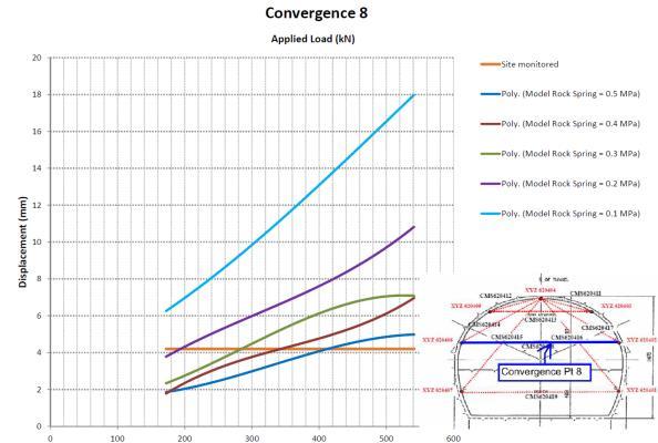
12 Figure 7.1 Onsite convergence monitoring points Both Terzaghi s Rock Load and the Q-system empirical methods assume the tunnel sections to be constant where the rock loads were applied in a 2-dimensional space. The mid-point of the adit tunnel convergence monitoring was adopted because it was considered that there was sufficient length of tunnel distance away from shaft and junction areas that could affect the convergence results due to the 3-dimensional geometrical effects during the mining works. The following graphs show the studies carried out for each convergence monitoring point comparing the 5 different rock springs (i.e 0.1 MPa, 0.2 MPa, 0.3 MPa, 0.4 MPa and 0.5 MPa) with the range of overburden loadings (i.e (B+H)) against the site monitored measurements. 12

13 13

14 From the above graphs, the most probable rock spring to be 0.2 MPa and the most probable applied rock load factor to be 0.4(B+H) = 196.8kN/m 2. Figure 7.2 Collated information from convergence, rock spring and rock load 8. Q-SYSTEM EMPIRICAL METHOD The Q-value observed at the adit location adopted for the numerical model approximately 20m from the shaft-adit junction location was 22.5 (see Table 6.3 Tunnel Mapping results). The depth of the tunnel at this location from the ground level to the tunnel crown is approximately 58.5m while the tunnel height and width is 9.5m and 11m respectively. The empirical equation for estimating the rock load (support pressure) [5] is P r = 0.1Q -1/3 (MPa) Eq. (4) Previous papers have found the correlation between the support pressures to be inversely proportional to the static modulus of deformation Em [4, 5]. Therefore the equation [9] is P r = 1/Em (MPa) Eq. (5) Where, Em = 25logQ (GPa) for Q > 1 From the above equations (4) and (5), the rock load was calculated to be 35kN/m 2 for equation (4) and 29.6kN/m 2 for equation (5). The range can be considered small, therefore the anticipated rock loads from both equations can be considered acceptable. 14
15 Support pressures was found to be inversely proportional to deformation modulus, a central trend for tunnel deformation is that Δ in millimeters is equal to the span in meters divided by Q [4]. Therefore, the equation gives Δ = Span / Q (mm) Eq. (6) Convergence 5 was selected for the Terzaghi Rock Load method, the span to be adopted shall be the similar length as convergence 5 which was estimated to be 11.7m. Hence equation (6) gives a Δ of 0.52mm. The recorded convergence was recorded to be 5.2mm which should be considered to be the total movement throughout the mining procedure that includes the vibrations from the blasting phase, therefore such small movements can be reasonable. 9. CONCLUSIONS The numerical model created was a wish-in place model without considerations for the staged construction sequence and the stabilization of the rock through the cumulative loosening process during the mining process. During the excavation sequences of the mined tunnel, the intact rock mass would have been disturbed and some beneficial rock loosening may have taken place. By the time of the excavation of the rock at that location, the rock mass would have stabilized thereby recording small displacements at the excavated face. Therefore the displacements obtained from the numerical model should be considered as the total displacement which can be expected to be larger than the actual displacement due to the rock load of the excavated tunnel. This explains the phenomenon where the monitored convergences obtained are generally smaller than the convergences obtained from the numerical model. However one must remember that the monitored convergences includes the vibrations effects from the blasting during the mining phase. This implies that the actual applied rock load should be lesser. Ground investigations carried out prior to the excavations suggested the rock quality to be Blocky to Seamy and Good to Fair. Throughout the mining process, the rock mass at the tunnel level was found to be Blocky and Good. This suggested that the rock mass strength should be 3.5 MPa or higher which would be more than the values adopted by all the numerical models. Therefore the displacements obtained from the numerical models will had been conservative. The Terzaghi s Rock Load Classification method for rock loads provides reasonable support pressure estimates for small tunnels but over estimates for tunnels having diameter more than 6m [2] and is generally applied to softer and/or weaker rocks condition with lower rock mass shear strength. Therefore the 196.8kN/m 2 [i.e 0.4(B+H)] rock load and 0.2 MPa rock spring discussed in this paper can still be considered to be conservative. 15
16 As mentioned above the quality of rock from site observations was found to be good, the Q-system empirical method discussed in this paper found to be approximately 5 times smaller at 35kN/m 2 can be considered to be reasonable since Q- system is best utilized for drill and blast tunnels [8]. This is consistent with author s opinion where the rock load obtained from Q- system empirical method should be lesser than the numerical method which would be more realistic to the actual case. Measured site convergence was also recorded to be small, i.e the largest measured was approximately 5.2mm (in total displacement). This is further evident in the small change in movement estimated to be 0.52mm. The above observations and findings further supports the author s opinion that the rock loads obtained from Q-system is considered more reasonable for good quality rock with sufficient rock cover. Understanding and adopting the suitable method based on the competency of the rock condition can help future tunnels to have an economical design whilst maintaining a safe environment during the construction process. This will also allow designers to better estimate the rock load to apply for more realistic and economical design for future deep tunnels. 10. ACKNOWLEDGMENTS The author would like to acknowledge the Singapore Power Assets Ltd and SK Engineering & Construction (Singapore) for their co-operation, review of the paper and agreement to utilize their data collected. The author would also like to thank colleagues Defence Science Technology Agency Singapore, in particular Dr Zhou Yingxin, and at WSP / Parsons Brinkerhoff for their time and efforts in their review of this paper. REFERENCES 1. Arild Palmstrom & Einar Broach (2006), Use and misuse of rock mass classification systems with particular reference to the Q-system 2. B.Singh & R.K Geol (1999), Rock mass classification: a practical approach in civil engineering: Amsterdam, Elsevier Science 3. E.Grimstad & N.Barton (1993), Updating the Q-system for NMT 4. N.R Barton (2013), Integrated empirical methods for the design of tunnels, shafts and caverns in rock, based on the Q-system 5. N.Barton (2002), Some new Q-value correlations to assist in site characterization and tunnel design 16
17 6. NGI 2015, Using the Q-system, Rock mass classification and support design 7. Singapore Power Asset (North-South Contract 2) Geological Baseline report 8. Singapore Power Asset (North-South Contract 2) Design Criteria and Performance Specifications, Civil and Structural Works 9. Syed Muntazir Abbas & Habil Heinz Konietzky (2016), Rock Mass Classification Systems 10. Terzaghi, K. (1946, pp15-99), Rock Defects and Loads on Tunnel Supports, In Rock tunneling with Steel Support eds R.V Proctor and T.L. White, Commercial Shearing Co., Youngstown, OHIO 17
Underground Excavation Design Classification
 Underground Excavation Design Underground Excavation Design Classification Alfred H. Zettler alfred.zettler@gmx.at Rock Quality Designation Measurement and calculation of RQD Rock Quality Designation index
COMPARING THE RMR, Q, AND RMi CLASSIFICATION SYSTEMS
 COMPARING THE RMR, Q, AND RMi CLASSIFICATION SYSTEMS PART 2: CORRELATIONS OF THE THREE SYSTEMS by Arild Palmström, Ph.D. RockMass AS, Oslo, Norway In Part 1, it was shown how the input parameters to the
NNN99. Rock Engineering for the Next Very Large Underground Detector. D. Lee Petersen CNA Consulting Engineers
 NNN99 Rock Engineering for the Next Very Large Underground Detector D. Lee Petersen Overview Rock engineering 101 Cavern size & shape Construction methods Feasibility Historical projects Numerical modeling
An introduction to the Rock Mass index (RMi) and its applications
 and its applications") Reference: A. Palmström, www.rockmass.net An introduction to the Rock Mass index (RMi) and its applications by Arild Palmström, Ph.D. 1 Introduction Construction materials commonly used in civil engineering
Reference: A. Palmström, www.rockmass.net An introduction to the Rock Mass index (RMi) and its applications by Arild Palmström, Ph.D. 1 Introduction Construction materials commonly used in civil engineering
Session 3: Geology and Rock Mechanics Fundamentals
 Session 3: Geology and Rock Mechanics Fundamentals Geotechnical Engineering Appreciation Course (Jointly organised by IES Academy and GeoSS) Dr Zhou Yingxin, Senior Principal Engineer, DSTA Adjuct Associate
Final design of Belesar III and Los Peares III Hydropower Projects. (Galicia, Spain).
.") Final design of Belesar III and Los Peares III Hydropower Projects. (Galicia, Spain). J. Baztán and A. Martín Gas Natural Fenosa Engineering, S.L.U, Madrid, Spain. J. M. Galera and D. Santos Subterra Ingeniería
Final design of Belesar III and Los Peares III Hydropower Projects. (Galicia, Spain). J. Baztán and A. Martín Gas Natural Fenosa Engineering, S.L.U, Madrid, Spain. J. M. Galera and D. Santos Subterra Ingeniería
EXAMINATION PAPER MEMORANDUM
 EXAMINATION PAPER MEMORANDUM SUBJECT: CERTIFICATE IN ROCK MECHANICS PAPER 3.1 : HARD ROCK TABULAR EXAMINER: PJ LE ROUX SUBJECT CODE: COMRMC EXAMINATION DATE: MAY 2015 TIME: MODERATOR: WM BESTER TOTAL MARKS:
Observational Methods and
 Observational Methods and NATM System for Observational approach to tunnel design Eurocode 7 (EC7) includes the following remarks concerning an observational method. Four requirements shall all be made
Instructional Objectives. Why use mass classification? What is rock mass classification? 3 Pillars of empirical design and rock mass classification
 GE 6477 DISCONTINUOUS ROCK 5. Rock Mass Classification and Empirical Design Dr. Norbert H. Maerz Missouri University of Science and Technology (573) 341-6714 norbert@mst.edu Instructional Objectives 1.
Seismic analysis of horseshoe tunnels under dynamic loads due to earthquakes
 University of Wollongong Research Online Coal Operators' Conference Faculty of Engineering and Information Sciences 2010 Seismic analysis of horseshoe tunnels under dynamic loads due to earthquakes Navid
ON THE FACE STABILITY OF TUNNELS IN WEAK ROCKS
 33 rd 33 Annual rd Annual General General Conference conference of the Canadian of the Canadian Society for Society Civil Engineering for Civil Engineering 33 e Congrès général annuel de la Société canadienne
MEMORANDUM SUBJECT: CERTIFICATE IN ROCK MECHANICS PAPER 1 : THEORY SUBJECT CODE: COMRMC MODERATOR: H YILMAZ EXAMINATION DATE: OCTOBER 2017 TIME:
 MEMORANDUM SUBJECT: CERTIFICATE IN ROCK MECHANICS PAPER 1 : THEORY EXAMINER: WM BESTER SUBJECT CODE: COMRMC EXAMINATION DATE: OCTOBER 2017 TIME: MODERATOR: H YILMAZ TOTAL MARKS: [100] PASS MARK: (60%)
Building on Past Experiences Worker Safety
 EOSC433: Geotechnical Engineering Practice & Design Lecture 11: Rock Stabilization Principles 1 of 43 Erik Eberhardt UBC Geological Engineering EOSC 433 (2016) Building on Past Experiences Worker Safety
Weak Rock - Controlling Ground Deformations
 EOSC 547: Tunnelling & Underground Design Topic 7: Ground Characteristic & Support Reaction Curves 1 of 35 Tunnelling Grad Class (2014) Dr. Erik Eberhardt Weak Rock - Controlling Ground Deformations To
In-situ Experiments on Excavation Disturbance in JNC s Geoscientific Research Programme
 In-situ Experiments on Excavation Disturbance in JNC s Geoscientific Research Programme H. Matsui, K. Sugihara and T. Sato Japan Nuclear Cycle Development Institute, Japan Summary The HLW disposal program
1 of 46 Erik Eberhardt UBC Geological Engineering ISRM Edition
 Rock Engineering Practice & Design Lecture 12: Rock Stabilization Principles 1 of 46 Erik Eberhardt UBC Geological Engineering ISRM Edition Author s Note: The lecture slides provided here are taken from
Geotechnical Monitoring for Safe Excavation of Large Rock Cavern: A Case Study
 The 31st International Symposium on Automation and Robotics in Construction and Mining (ISARC 2014) Geotechnical Monitoring for Safe Excavation of Large Rock Cavern: A Case Study A.Mandal a, C. Kumar b,
DESIGN AND CONSTRUCTION OF LARGE
 DESIGN AND CONSTRUCTION OF LARGE TUNNELS IN SOIL AND FAULTED ROCK SENTVID TUNNEL MOTORWAY BYPASS OF LJUBLJANA Josef Daller, ic consulenten, Vienna - Austria International NATM Workshop Singapore 2010 LAYOUT
ENGINEERING GEOLOGY AND ROCK ENGINEERING
 1 ENGINEERING GEOLOGY AND ROCK ENGINEERING HANDBOOK NO. 2 Norwegian Group for Rock Mechanics (NBG) www.bergmekanikk.com Prepared in co-operation with Norwegian Tunnelling Society (NFF) Issued in 2000 SECRETARIAT:
Entrance exam Master Course
 - 1 - Guidelines for completion of test: On each page, fill in your name and your application code Each question has four answers while only one answer is correct. o Marked correct answer means 4 points
Introduction and Background
 Introduction and Background Itasca Consulting Group, Inc. (Itasca) has been participating in the geomechanical design of the underground 118-Zone at the Capstone Minto Mine (Minto) in the Yukon, in northwestern
Geotechnical & Mining Engineering Services
 Geotechnical & Mining Engineering Services Southwest Research Institute San Antonio, Texas A s an independent, nonprofit research and development organization, Southwest Research Institute (SwRI ) uses
Numerical modelling for estimation of first weighting distance in longwall coal mining - A case study
 University of Wollongong Research Online Coal Operators' Conference Faculty of Engineering and Information Sciences 2012 Numerical modelling for estimation of first weighting distance in longwall coal
Correlation of Revised BQ System in China and the International Rock Mass Classification Systems
 Journal of Civil Engineering Research 2015, 5(2): 33-38 DOI: 10.5923/j.jce.20150502.03 Correlation of Revised BQ System in China and the Yan Rui-Xin, Shen Yan-Jun * School of Architecture and Civil Engineering,
Rock-Quality Study at Tunnel Site in the Kameng Hydro-Electric Project, Bichom, Arunachal Pradesh, India
 Open access e-journal Earth Science India, eissn: 0974 8350 Vol. 9 (I), January, 2016, pp. 21-28 http://www.earthscienceindia.info/ Rock-Quality Study at Tunnel Site in the Kameng Hydro-Electric Project,
H.Öztürk & E.Ünal Department of Mining Engineering, Middle East Technical University, Ankara, Turkey
 17th International Mining Congress and Exhibition of Turkey- IMCET2001, 2001, ISBN 975-395-417-4 Estimation of Lining Thickness Around Circular Shafts H.Öztürk & E.Ünal Department of Mining Engineering,
SYLLABUS AND REFERENCES FOR THE STRATA CONTROL CERTIFICATE. METALLIFEROUS MINING OPTION Updated November 1998
 CHAMBER OF MINES OF SOUTH AFRICA SYLLABUS AND REFERENCES FOR THE STRATA CONTROL CERTIFICATE METALLIFEROUS MINING OPTION Updated November 1998 1 PART 1 : THEORY 1.1 Basic principles of rock engineering
Numerical Approach to Predict the Strength of St. Peter Sandstone Pillars acted upon by Vertical Loads A case study at Clayton, IA, USA.
 IOSR Journal of Engineering (IOSRJEN) ISSN (e): 2250-3021, ISSN (p): 2278-8719 Vol. 05, Issue 01 (January. 2015), V2 PP 36-41 www.iosrjen.org Numerical Approach to Predict the Strength of St. Peter Sandstone
Ground support modelling involving large ground deformation: Simulation of field observations Part 1
 Ground Support 2016 E. Nordlund, T.H. Jones and A. Eitzenberger (eds) Ground support modelling involving large ground deformation: Simulation of field observations Part 1 D.Saiang, Luleå University of
Influence of foliation on excavation stability at Rampura Agucha underground mine
 Recent Advances in Rock Engineering (RARE 2016) Influence of foliation on excavation stability at Rampura Agucha underground mine P Yadav, A Panda, M Sonam, B Banerjee, S Parihar, and DC Paneri Geotechnical
Numerical analysis of K0 to tunnels in rock masses exhibiting strain-softening behaviour (Case study in Sardasht dam tunnel, NW Iran)
") International Research Journal of Applied and Basic Sciences 2013 Available online at www.irjabs.com ISSN 2251-838X / Vol, 4 (6): 1572-1581 Science Explorer Publications Numerical analysis of K0 to tunnels
International Research Journal of Applied and Basic Sciences 2013 Available online at www.irjabs.com ISSN 2251-838X / Vol, 4 (6): 1572-1581 Science Explorer Publications Numerical analysis of K0 to tunnels
Calculation of periodic roof weighting interval in longwall mining using finite element method
 Calculation of periodic roof weighting interval in longwall mining using finite element method Navid Hosseini 1, Kamran Goshtasbi 2, Behdeen Oraee-Mirzamani 3 Abstract The state of periodic loading and
7. Foundation and Slope Stability
 The Asian Nuclear Safety Network 7. Foundation and Slope Stability (SER 2.5.4 & 2.5.5) Taek-Mo SHIM k147stm@kins.re.kr Korea Institute of Nuclear Safety Structural Systems and Site Evaluation Department
ROCK MASS PROPERTIES FOR TUNNELLING
 ROCK MASS PROPERTIES FOR TUNNELLING Robert Bertuzzi 2 nd November 2017 1 Driver Estimating the strength and deformation characteristics of a rock mass for tunnel design is generally based on empiricism
Rock slope rock wedge stability
 Engineering manual No. 28 Updated: 02/2018 Rock slope rock wedge stability Program: Rock stability File: Demo_manual_28.gsk The aim of the chapter of this engineering manual is to explain a rock slope
A PROBABILISTIC APPROACH FOR CHARACTERIZING THE COMPLEX GEOLOGIC ENVIRONMENT FOR DESIGN OF THE NEW METRO DO PORTO
 AITES-ITA 2001 World Tunnel Congress PROGRESS IN TUNNELING AFTER 2000 Milano, June 10-13, 2001 Volume III, pp. 463-470 A PROBABILISTIC APPROACH FOR CHARACTERIZING THE COMPLEX GEOLOGIC ENVIRONMENT FOR DESIGN
10. GEOTECHNICAL EXPLORATION PROGRAM
 Geotechnical site investigations should be conducted in multiple phases to obtain data for use during the planning and design of the tunnel system. Geotechnical investigations typically are performed in
Successful Construction of a Complex 3D Excavation Using 2D and 3D Modelling
 University of Wollongong Research Online Coal Operators' Conference Faculty of Engineering and Information Sciences 2015 Successful Construction of a Complex 3D Excavation Using 2D and 3D Modelling Yvette
SERVICEABILITY LIMIT STATE DESIGN
 CHAPTER 11 SERVICEABILITY LIMIT STATE DESIGN Article 49. Cracking Limit State 49.1 General considerations In the case of verifications relating to Cracking Limit State, the effects of actions comprise
Moglicë HPP - Albania. Jorge Terron
 Moglicë HPP - Albania Jorge Terron DEVOLL MOGLICË PROJECT Background Location Project Summary Sweco duties Plant overview Geology Cavern complex Layout Site investigations Rock mass characterization Geology
Two Case Studies on Soil Nailed Slope Failures
 Two Case Studies on Soil Nailed Slope Failures Liew, Shaw-Shong 1 & Liong, Chee-How 2 1 Director, Gue & Partners Sdn Bhd, Kuala Lumpur, Malaysia 2 Senior Engineer, Gue & Partners Sdn Bhd, Kuala Lumpur,
Ground Support in Mining and Underground Construction
 Ground Support in Mining and Underground Construction Proceedings of the Fifth International Symposium on Ground Support 28-30 September 2004, Perth, Western Australia Edited by Ernesto Villaescusa Yves
Appraisal of Soil Nailing Design
 Indian Geotechnical Journal, 39(1), 2009, 81-95 Appraisal of Soil Nailing Design G. L. Sivakumar Babu * and Vikas Pratap Singh ** Introduction Geotechnical engineers largely prefer soil nailing as an efficient
The effect of installation angle of rock bolts on the stability of rock slopes
 Journal of Novel Applied Sciences Available online at www.jnasci.org 2015 JNAS Journal-2015-4-1/67-71 ISSN 2322-5149 2015 JNAS The effect of installation angle of rock on the stability of rock slopes Mehran
Stability Assessment of a Heavily Jointed Rock Slope using Limit Equilibrium and Finite Element Methods
 Indian Geotechnical Conference 2017 GeoNEst 14-16 December 2017, IIT Guwahati, India Stability Assessment of a Heavily Jointed Rock Slope using Limit Equilibrium and Finite Element Methods Aswathi CK Amalesh
Borehole Camera And Extensometers To Study Hanging Wall Stability Case Study Using Voussoir beam - Cuiabá Mine
 Rock Mechanics for Natural Resources and Infrastructure ISRM Specialized Conference 09-13 September, Goiania, Brazil CBMR/ABMS and ISRM, 2014 Borehole Camera And Extensometers To Study Hanging Wall Stability
Estimates of rock mass strength and deformation modulus
 Discussion paper # 4 Estimates of rock mass strength and deformation modulus In the preliminary stages of a rock engineering design the need for approximate estimates of rock mass strength and deformation
Flin Flon Mining Belt
 EOSC433: Geotechnical Engineering Practice & Design Lecture 7: Stress Analysis around Underground Openings 1 of 40 Erik Eberhardt UBC Geological Engineering EOSC 433 (2007) Flin Flon Mining Belt Since
Boreholes. Implementation. Boring. Boreholes may be excavated by one of these methods: 1. Auger Boring 2. Wash Boring 3.
 Implementation Boreholes 1. Auger Boring 2. Wash Boring 3. Rotary Drilling Boring Boreholes may be excavated by one of these methods: 4. Percussion Drilling The right choice of method depends on: Ground
Determination of stope geometry in jointed rock mass at Pongkor Underground Gold Mine
 Volume 5, Number 2, April 2009, pp.63-68 [TECHNICAL NOTES] Determination of stope geometry in jointed rock mass at Pongkor Underground Gold Mine Budi SULISTIANTO *, M. Safrudin SULAIMAN **, Ridho Kresna
Eurocode 7 from soil mechanics to rock mechanics. Luís Lamas, LNEC, Lisbon, Portugal Didier Virely, CEREMA, Toulouse, France
 Eurocode 7 from soil mechanics to rock mechanics Luís Lamas, LNEC, Lisbon, Portugal Didier Virely, CEREMA, Toulouse, France Contents 1. The discontinuous nature of rock mass 2. Design methods 3. Calculation
Feasibility of dynamic test methods in classification of damaged bridges
 Feasibility of dynamic test methods in classification of damaged bridges Flavio Galanti, PhD, MSc., Felieke van Duin, MSc. TNO Built Environment and Geosciences, P.O. Box 49, 26 AA, Delft, The Netherlands.
1. Rock Mechanics and mining engineering
 1. Rock Mechanics and mining engineering 1.1 General concepts Rock mechanics is the theoretical and applied science of the mechanical behavior of rock and rock masses; it is that branch of mechanics concerned
Table of Contents Development of rock engineering 2 When is a rock engineering design acceptable 3 Rock mass classification
 Table of Contents 1 Development of rock engineering...1 1.1 Introduction...1 1.2 Rockbursts and elastic theory...4 1.3 Discontinuous rock masses...6 1.4 Engineering rock mechanics...7 1.5 Geological data
Estimation of support requirement for large diameter ventilation shaft at Chuquicamata underground mine in Chile
 Harmonising Rock Engineering and the Environment Qian & Zhou (eds) 2012 Taylor & Francis Group, London, ISBN 978-0-415-80444-8 Estimation of support requirement for large diameter ventilation shaft at
Critical Borehole Orientations Rock Mechanics Aspects
 Critical Borehole Orientations Rock Mechanics Aspects By R. BRAUN* Abstract This article discusses rock mechanics aspects of the relationship between borehole stability and borehole orientation. Two kinds
Rock mass classification systems
 Authors: Syed Muntazir Abbas (TU Bergakademie Freiberg, Geotechnical Institute, and National Centre of Excellence in Geology, University of Peshawar) & Prof. Dr. habil. Heinz Konietzky (TU Bergakademie
ROCK MASS CHARACTERISATION IN ENGINEERING PRACTICE
 Paul MARINOS NTUA, School of Civil Engineering, 9 Iroon Polytechniou str., Athens, 157 80, Greece, e-mail : marinos@central.ntua.gr ROCK MASS CHARACTERISATION IN ENGINEERING PRACTICE 1. INTRODUCTION The
Rockburst mitigation experiences on underground projects in the Cheves Hydropower project in the Peruvian Andes
 Paper No. 156 ISMS 2016 Rockburst mitigation experiences on underground projects in the Cheves Hydropower project in the Peruvian Andes Santiago Veyrat a, Jose-Miguel Galera b, *, Marcos Sancho c a Subterra
TBM "Boreability" in Hard Rock
 JMConsulting-Rock Engineering TBM "Boreability" in Hard Rock Javier Macias, PhD Rock Engineering Consultant and Researcher JMConsulting-Rock Engineering AS Anvendt bergmekanikk 10.01.2018, Trondheim Outline
R13. II B. Tech I Semester Regular Examinations, Jan MECHANICS OF SOLIDS (Com. to ME, AME, AE, MTE) PART-A
 PART-A") SET - 1 II B. Tech I Semester Regular Examinations, Jan - 2015 MECHANICS OF SOLIDS (Com. to ME, AME, AE, MTE) Time: 3 hours Max. Marks: 70 Note: 1. Question Paper consists of two parts (Part-A and Part-B)
SET - 1 II B. Tech I Semester Regular Examinations, Jan - 2015 MECHANICS OF SOLIDS (Com. to ME, AME, AE, MTE) Time: 3 hours Max. Marks: 70 Note: 1. Question Paper consists of two parts (Part-A and Part-B)
Structurally controlled instability in tunnels
 Structurally controlled instability in tunnels Introduction In tunnels excavated in jointed rock masses at relatively shallow depth, the most common types of failure are those involving wedges falling
Chapter (6) Geometric Design of Shallow Foundations
 Geometric Design of Shallow Foundations") Chapter (6) Geometric Design of Shallow Foundations Introduction As we stated in Chapter 3, foundations are considered to be shallow if if [D (3 4)B]. Shallow foundations have several advantages: minimum
Chapter (6) Geometric Design of Shallow Foundations Introduction As we stated in Chapter 3, foundations are considered to be shallow if if [D (3 4)B]. Shallow foundations have several advantages: minimum
SYLLABUS AND REFERENCES FOR THE STRATA CONTROL CERTIFICATE COAL MINING OPTION
 CHAMBER OF MINES OS SOUTH AFRICA SYLLABUS AND REFERENCES FOR THE STRATA CONTROL CERTIFICATE COAL MINING OPTION 1. PART 1 : THEORY 1.1 Basic principles of rock engineering 1.1.1 Terms, definitions and basic
Quantitative Classification of Rock Mass
 Quantitative Classification of Rock Mass Description of Joints: Orientation, Persistence, Roughness, Wall Strength, Aperture, Filling, Seepage, Number of sets, Block size, spacing. ISRM commission s i
Geotechnical project work flow
 Wulf Schubert INTRODUCTION The approach to solve an engineering problem is to combine experience with analysis The more complex the conditions are, the more difficult a direct analysis becomes, as appropriate
Structural Analysis I Chapter 4 - Torsion TORSION
 ORSION orsional stress results from the action of torsional or twisting moments acting about the longitudinal axis of a shaft. he effect of the application of a torsional moment, combined with appropriate
Module 5: Failure Criteria of Rock and Rock masses. Contents Hydrostatic compression Deviatoric compression
 FAILURE CRITERIA OF ROCK AND ROCK MASSES Contents 5.1 Failure in rocks 5.1.1 Hydrostatic compression 5.1.2 Deviatoric compression 5.1.3 Effect of confining pressure 5.2 Failure modes in rocks 5.3 Complete
Purpose of this Guide: To thoroughly prepare students for the exact types of problems that will be on Exam 3.
 ES230 STRENGTH OF MTERILS Exam 3 Study Guide Exam 3: Wednesday, March 8 th in-class Updated 3/3/17 Purpose of this Guide: To thoroughly prepare students for the exact types of problems that will be on
Engineeringmanuals. Part2
 Engineeringmanuals Part2 Engineering manuals for GEO5 programs Part 2 Chapter 1-12, refer to Engineering Manual Part 1 Chapter 13. Pile Foundations Introduction... 2 Chapter 14. Analysis of vertical load-bearing
DESIGN AND DETAILING OF COUNTERFORT RETAINING WALL
 DESIGN AND DETAILING OF COUNTERFORT RETAINING WALL When the height of the retaining wall exceeds about 6 m, the thickness of the stem and heel slab works out to be sufficiently large and the design becomes
Application of Core Logging Data to generate a 3D Geotechnical Block Model
 Application of Core Logging Data to generate a 3D Geotechnical Block Model Engineering Geology and Innovation: Research Infrastructure - Sustainable Development (I.A.E.G) Eleftheria Vagkli, M.Sc. Senior
Appendix 6 Geotechnical report
 Page 56 Appendix 6 Geotechnical report 1. Introduction The following provides an initial and preliminary description/assessment of the overall geology, the likely ground conditions and preliminary geotechnical
Determination of the coefficient of earth pressure at rest in situ in overconsolidated clay
 World Tunnel Congress 2008 - Underground Facilities for Better Environment and Safety - India Determination of the coefficient of earth pressure at rest in situ in overconsolidated clay Eszter Kalman Budapest
GROUND RESPONSE AND SUPPORT MEASURES FOR PIR PANJAL TUNNEL IN THE HIMALAYAS
 Ground IGC 2009, Response Guntur, and INDIA Support Measures for Pir Panjal Tunnel in the Himalayas GROUND RESPONSE AND SUPPORT MEASURES FOR PIR PANJAL TUNNEL IN THE HIMALAYAS K.S. Rao Professor, Department
Some Aspects on the Design of Near Surface. Tunnels - Theory and Practice. Thomas Marcher¹, Taner Aydogmus²
 Mitteilungen für Ingenieurgeologie und Geomechanik Band 10 6 th Colloquium Rock Mechanics Theory and Practice p. 179-188 Wien 2013 Some Aspects on the Design of Near Surface Tunnels - Theory and Practice
The effect of dip of joints on the axial force of rock bolts
 Journal of Novel Applied Sciences Available online at www.jnasci.org 2015 JNAS Journal-2015-4-4/457-462 ISSN 2322-5149 2015 JNAS The effect of dip of joints on the axial force of rock bolts Farzad bayat
Design and implementation of a damage assessment system at Argyle Diamond s block cave project
 Caving 2010 Y. Potvin (ed) 2010 Australian Centre for Geomechanics, Perth, ISBN 978-0-9806154-1-8 https://papers.acg.uwa.edu.au/p/1002_1_fernandez/ Design and implementation of a damage assessment system
Minimization Solutions for Vibrations Induced by Underground Train Circulation
 Minimization Solutions for Vibrations Induced by Underground Train Circulation Carlos Dinis da Gama 1, Gustavo Paneiro 2 1 Professor and Head, Geotechnical Center of IST, Technical University of Lisbon,
EOSC433: Geotechnical Engineering Practice & Design
 EOSC433: Geotechnical Engineering Practice & Design Lecture 1: Introduction 1 of 31 Dr. Erik Eberhardt EOSC 433 (Term 2, 2005/06) Overview This course will examine different principles, approaches, and
Progress with the excavation and support of the Mingtan power cavern roof
 Progress with the excavation and support of the Mingtan power cavern roof D. Moy, Golder Associates, (UK) Ltd. E. Hoek, University of Toronto Originally published as: Moy, D. and Hoek, E. 1989. Progress
Deformability Modulus of Jointed Rocks, Limitation of Empirical Methods and Introducing a New Analytical Approach
 University of Wollongong Research Online Coal Operators' Conference Faculty of Engineering and Information Sciences 2016 Deformability Modulus of Jointed Rocks, Limitation of Empirical Methods and Introducing
Experimental Research on Ground Deformation of Double Close-spaced Tunnel Construction
 Research Journal of Applied Sciences, Engineering and Technology 4(22): 484-4844, 212 ISSN: 24-7467 Maxwell Scientific Organization, 212 Submitted: May 8, 212 Accepted: June 8, 212 Published: November
A new design approach for highway rock slope cuts based on ecological environment protection
 A new design approach for highway rock slope cuts based on ecological environment protection T. Lian-jin, Z. Li, W. Yunjie, W. Guang-yuan & Z. Yin-tao College of Architecture and Civil Engineering, Beijing
Module 9 : Foundation on rocks. Content
 FOUNDATION ON ROCKS Content 9.1 INTRODUCTION 9.2 FOUNDATION TYPES ON ROCKS 9.3 BEARING CAPCITY- SHALLOW FOUNDATION 9.3.1 Ultimate bearing capacity 9.3.2 Safe bearing pressure 9.3.3 Estimation of bearing
Department of National Defence B-Jetty Reconstruction
 Department of National Defence B-Jetty Reconstruction CFB Esquimalt, BC Presented by: Stantec & Golder Associates February 2, 2016 Agenda 1 B-Jetty Project Background 2 Distinguishing Project Features
LICENTIATE THESIS. Evaluation of rock mass strength criteria. Catrin Edelbro
 LICENTIATE THESIS Evaluation of rock mass strength criteria Catrin Edelbro Department of Civil and Environmental Engineering Division of Rock Mechanics BACKGROUND BACKGROUND Correct input data Reliable
In situ fracturing mechanics stress measurements to improve underground quarry stability analyses
 In situ fracturing mechanics stress measurements to improve underground quarry stability analyses Anna M. Ferrero, Maria R. Migliazza, Andrea Segalini University of Parma, Italy Gian P. Giani University
University of Sheffield The development of finite elements for 3D structural analysis in fire
 The development of finite elements for 3D structural analysis in fire Chaoming Yu, I. W. Burgess, Z. Huang, R. J. Plank Department of Civil and Structural Engineering StiFF 05/09/2006 3D composite structures
K Design Graphs and Charts for Raft Foundations Spanning Local Depressions
 K Design Graphs and Charts for Raft Foundations Spanning Local Depressions The reader is advised to read the text in Chapter 13 before using these charts. The charts and figures are repeated here for quick
Geotechnical data from optical and acoustic televiewer surveys
 Geotechnical data from optical and acoustic televiewer surveys by Farrin De Fredrick MAusIMM, Senior Geotechnical Engineer; Ta Nguyen AIG, Geotechnical Engineer; Clive Seymour MAusIMM, Principal; and Gary
R Long term stability of rock caverns BMA and BLA of SFR, Forsmark. Diego Mas Ivars, María Veiga Ríos Itasca Consultants AB
 R-13-53 Long term stability of rock caverns and of SFR, Forsmark Diego Mas Ivars, María Veiga Ríos Itasca Consultants AB Wenjie Shiu, Itasca Consultants SAS Fredrik Johansson, Anders Fredriksson Sweco
Study of Soft Rock Roadway Support Technique
 Available online at www.sciencedirect.com Procedia Engineering 26 (2011) 321 326 First International Symposium on Mine Safety Science and Engineering Study of Soft Rock Roadway Support Technique Haifeng
Application of a transversely isotropic brittle rock mass model in roof support design
 University of Wollongong Research Online Coal Operators' Conference Faculty of Engineering and Information Sciences 2012 Application of a transversely isotropic brittle rock mass model in roof support
Three-Dimensional Failure Criteria Based on the Hoek Brown Criterion
 Rock Mech Rock Eng () 45:989 99 DOI.7/s6--77- ISRM SUGGESTED METHOD Three-Dimensional Failure Criteria Based on the Hoek Brown Criterion Stephen Priest Published online: 8 July Ó Springer-Verlag List of
DETERMINING THE STRESS PATTERN IN THE HH RAILROAD TIES DUE TO DYNAMIC LOADS 1
 PERIODICA POLYTECHNICA SER. CIV. ENG. VOL. 46, NO. 1, PP. 125 148 (2002) DETERMINING THE STRESS PATTERN IN THE HH RAILROAD TIES DUE TO DYNAMIC LOADS 1 Nándor LIEGNER Department of Highway and Railway Engineering
THEME A. Analysis of the elastic behaviour of La Aceña arch-gravity dam
 THEME A Analysis of the elastic behaviour of La Aceña arch-gravity dam Gjorgi KOKALANOV, Professor, Faculty of Civil Eng., Skopje, Republic of Macedonia Ljubomir TANČEV, Professor, Faculty of Civil Eng.,
The Preliminary Study of the Impact of Liquefaction on Water Pipes
 The Preliminary Study of the Impact of Liquefaction on Water Pipes Jerry J. Chen and Y.C. Chou ABSTRACT Damages to the existing tap-water pipes have been found after earthquake. Some of these damages are
CHAPTER 4. Design of R C Beams
 CHAPTER 4 Design of R C Beams Learning Objectives Identify the data, formulae and procedures for design of R C beams Design simply-supported and continuous R C beams by integrating the following processes
Rock parameters for blasting on the highway Split-Dubrovnik
 Rock Engineering in Difficult Ground Conditions Soft Rocks and Karst Vrkljan (ed) 2010 Taylor & Francis Group, London, ISBN 978-0-415-80481-3 Rock parameters for blasting on the highway Split-Dubrovnik