LOCATION RESTRICTION EVALUATION
|
|
|
- Kory Bradley
- 5 years ago
- Views:
Transcription
1 Prepared for Buckeye Power, Inc 6677 Busch Blvd. Columbus, Ohio LOCATION RESTRICTION EVALUATION CARDINAL FAR II BRILLIANT, OHIO Prepared by 1420 Kensington Road, Suite 103 Oak Brook, Illinois Geosyntec Project No.: CHE8126L CHA8468 August 2018
2 LOCATION RESTRICTION EVALUATION CARDINAL FAR II BRILLIANT, OHIO TABLE OF CONTENTS 1. OBJECTIVE Purpose Organization of Report Coordinate System and Datum BACKGROUND INFORMATION Facility Location Description Description of CCR Units Embankment Configuration Area and Volume Construction and Operational History Surface Water Control Previous Investigations Hydrogeologic Setting Climate Regional and Local Geologic Setting Surface Water and Surface Water-Groundwater Interactions Water Users REQUIRED ISOLATION FROM UPPERMOST AQUIFER Aquifer Description and Piezometric Analysis Fly Ash Reservoir II Compliance Fly Ash Reservoir II WETLANDS IMPACT Review of Local Wetlands Compliance FAULT AREAS CHE8126L\Cardinal_FAR II LOR Rpt _ i August 2018
3 5.1 Regional Geologic Structural Features and Tectonic Setting Compliance SEISMIC IMPACT ZONES Definition and Regional information Compliance UNSTABLE AREAS Definition and Review of Local Conditions Compliance Areas Susceptible to Bearing Capacity, Static Stability, Seismic Stability or Settlement Failures Areas Susceptible to Liquefaction Areas Susceptible to Mass Movements Areas Impacted By Natural and Human Induced Activities Presence of Karst Terrain Areas Susceptible to Coastal and River Erosion Summary of Unstable Area Compliance Assessment RECOMMENDATIONS CERTIFICATION BY A QUALIFIED PROFESSIONAL ENGINEER CHE8126L\Cardinal_FAR II LOR Rpt _ ii August 2018
4 LIST OF FIGURES Figure 2-1 Figure 2-2 Figure 2-3 Figure 2-4 Figure 4-1 Figure 5-1 Figure 6-1 Figure 7-1 Figure 7-2 Plant and CCR Unit Location Map FAR II Reservoir General Arrangement Raised Dam Site Plan Typical Dam Cross Sections and Details FAR I RSW Landfill and FAR II Wetland Fault Areas in Ohio Deaggregation Analysis for Cardinal FAR II FAR I RSW Landfill and FAR II Underground Mine Locations Ohio Karst Areas LIST OF APPENDICES Appendix A References CHE8126L\Cardinal_FAR II LOR Rpt _ iii August 2018
5 LIST OF ACRONYMS AEP BAC Buckeye CCR ESP FAD FAR FGD g gpm mg/l MSE NPDES ODNR OAC PGA PFBC PMF RCC RWL SCR TDS USACE USEPA USFWS USGS American Electric Power Bottom Ash Complex Buckeye Power Coal Combustion Residual Electrostatic Precipitators Fly Ash Dam Fly Ash Reservoir Flue Gas Desulphurization acceleration due to gravity gallons per minute milligram per liter Mechanically Stabilized Earth National Pollutant Discharge Elimination System Ohio Department of Natural Resources Ohio Administrative Code Peak Ground Acceleration Pressurized Fluidized Bed Combustion Probable Maximum Flood Roller Compacted Concrete (Compacted Cement Bottom Ash Fill) Residual Waste Landfill Selective Catalytic Reduction Total Dissolved Solids United States Army Corps of Engineers United States Environmental Protection Agency United States Fish and Wildlife Service United States Geological Survey CHE8126L\Cardinal_FAR II LOR Rpt _ iv August 2018
6 1. OBJECTIVE 1.1 Purpose The purpose of this report is to provide an assessment of the Location Restriction Requirements associated with the Fly Ash Reservoir II (FAR II) at the Cardinal Operating Company s Cardinal Plant relative to its compliance with the United States Environmental Protection Agency (USEPA) Coal Combustion Residual (CCR) Rule Sections 40 CFR , 61, 62, 63 and 64. This original report was prepared in accordance with American Electric Power (AEP) Company s Letter of Authorization x104. The revised and updated report was prepared for Buckeye Power, Inc., (Buckeye), 1.2 Organization of Report This report is organized as follows: Section 2 presents background information on the power plant and the CCR units; Section 3 presents an evaluation of the CCR unit with respect to the elevation of the base of the unit above the uppermost aquifer (40 CFR (a)); Section 4 presents an evaluation of the CCR unit with respect to wetlands (40 CFR ); Section 5 presents an evaluation of the CCR unit with respect to fault areas (40 CFR ); Section 6 presents an evaluation of the CCR unit with respect to seismic impact zones (40 CFR ); Section 7 presents an evaluation of the CCR unit with respect to unstable areas (40 CFR ); Section 8 provides recommendations to address non-compliances and requests additional information; and Section 9 provides a certification from a qualified Professional Engineer (PE). CHE8126L\Cardinal_FAR II LOR Rpt _ August 2018
7 1.3 Coordinate System and Datum The horizontal coordinate values provided in this report are based upon the North American Datum of 1927 (NAD27). The vertical datum utilized for reporting the elevations within this report is National Geodetic Vertical Datum of 1929 (NGVD 29). CHE8126L\Cardinal_FAR II LOR Rpt _ August 2018
8 2. BACKGROUND INFORMATION 2.1 Facility Location Description The Cardinal Plant is a three-unit, 1,830 MW total capacity coal-fired generating station located in Jefferson County south of Brilliant, Ohio along the Ohio River. Each generating unit is equipped with an electrostatic precipitator (ESP) for removal of fly ash particulate matter, a selective catalytic reduction (SCR) system for removal of nitrogen oxide, and flue gas desulphurization (FGD) systems for removal of sulfur dioxide (AEP 2005a; AEP 2014). The existing CCR unit considered in this evaluation is the Fly Ash Reservoir II (FAR II). FAR II and its location with respect to FAR 1 RSW Landfill, the Bottom Ash Complex (BAC) and the main plant area are shown on Figure 2-1. Reference to FAR II in reference documents use both the FAR II and FAR 2 designations, but they are referring to the same reservoir. 2.2 Description of CCR Units FAR II is an existing wet fly ash disposal reservoir that is located approximately one-mile north of the plant site and east of FAR 1 RSW Landfill. The reservoir is contained within Blockhouse Hollow (also referred to as Blockhouse Run in references and drawings) by Fly Ash Dam 2 (FAD 2) and the decommissioned Fly Ash Dam 1 (FAD 1). FAR II receives stormwater and leachate (treated for neutralization) from the landfill. FAR II/FAD 2 has a permitted discharge through NPDES Outfall 019 (AEP, 2005a) Embankment Configuration FAR II is contained within the north (main) branch of Blockhouse Hollow, by FAD 1 and FAD 2. FAR 1 has been filled with ash and holds no surface water on the upstream side of FAD 1. FAD 1, on the southeast (downstream) side, contains FAR II water and ash along the downstream slope which is 2.5H:1V. FAD 1 has a top-of-dam elevation of ft. Figure 2-2 shows the FAR II General Arrangement plan provided in the permit application for raising the FAD 2. The raising embankment details are discussed below. The FAR II maximum design operating pool elevation is ft and the PMF elevation is ft (AEP, 2012). FAD 2 is approximately 1,400-ft long and 230-ft high and was raised in 2013 from a dam crest elevation of ft to a crest elevation of ft (AEP, 2012). The previous dam crest width was approximately 30 ft with the top fill consisting of 9 ft of roller compacted concrete (consisting of cement and bottom ash mixture) placed and compacted in lifts. The slopes of the previous dam were unchanged as the dam raising consisted of constructing back-to-back mechanically stabilized earth (MSE) walls, filling in the old spillway, and constructing a new emergency spillway, and raising the existing principal (service) spillway structure. The MSE structure is approximately 21.3-ft wide and contains a 36-ft long vinyl sheetpile vertical cutoff installed within a cement- CHE8126L\Cardinal_FAR II LOR Rpt _ August 2018
9 bentonite slurry trench. The sheetpile toe and trench bottom extend to a minimum of three feet into the clay core of the existing earth dam. Figures 2-3 and 2-4 show the Raised Dam Site Plan and Typical Dam Cross Sections and Details, respectively, taken from the dam raising permit drawings AEP (2012) Area and Volume FAR II has a maximum surface area to the top of dam of approximately 184 acres and receives sluiced fly ash from the generating unit s ESPs. A total of 161 acres at maximum pool will be used for ash waste placement (AEP, 2012). The remaining area is occupied by associated facilities, including leachate treatment facilities, monitoring wells and stormwater conveyances. The Cardinal generating units produce 560,000 cubic yards of fly ash per year. The raising of FAD 2 increased the storage capacity by 2,068 acre-feet such that FAR II can operate and receive ash until 2019, which is approximately 4 more years (AEP, 2012) Construction and Operational History FAR II began receiving ash after FAD 2 construction was completed and approved. FAR 1 received Cardinal ash only until 1988, although AEP was authorized to place the Tidd Plant PFBC ash until 1995 as part of a clean coal demonstration project (AEP 2005a). FAR 1 has been undergoing closure capping and all sluiced or trucked ash from the plants goes too FAR II. As indicated in Section 2.2.2, FAR II is scheduled to receive ash through the year Surface Water Control Surface water draining into FAR II is collected within the main (north) branch of Blockhouse Hollow and contained FAD 2 and discharged as part of the ash reservoir water through the FAD 2 principal or service spillway. The spillway is a concrete lined spillway located on the upstream face of the dam. The dam raising changed the top portion of the spillway to a vertical stop log structure. The maximum operating water level elevation is ft. The discharge is through a 54-inch diameter prestressed concrete pipe which exits through the bottom of the dam into a concrete portal flowing to an energy dissipater and a weir for monitoring (AEP, 2012). 2.3 Previous Investigations Current geotechnical assessments and permit applications with regard to raising the FAR II dam (FAD 2) and the reservoir water level have been completed with an emphasis on embankment stability and safe operating conditions, and wetland mitigation. They are as follows: Assessment of Dam Safety Coal Combustion Surface Impoundments (Task 3) (Final Report). December, CHA Companies. CHE8126L\Cardinal_FAR II LOR Rpt _ August 2018
10 Dam Raising Design Summary Cardinal Fly Ash Retention Pond II Waste Water PTI Application, April 2012, Submitted to OEPA Division of Water Surface, AEP Service Corp. and S&ME, Inc. Dam Raising Design Report Cardinal Fly Ash Reservoir No. 2, January 2013, Submitted to ODNR Division of Soil and Water Resources, AEP Service Corp. and S&ME, Inc., and Revised Permit Application Comment Response, January 16,2013. Nationwide Permit 39, Permit No , issued for purposes of Section 404 of Clean Water Act, December 2013, Corps of Engineers, Pittsburgh District. Fly Ash Reservoir II Dam Initial Safety Factor Assessment, September 18, Because surface runoff, subsurface drainage, and leachate collected from the FAR I RSW Landfill discharges into FAR II, monitoring wells from the former FAR I, FAR II, and the landfill were incorporated into one facility-wide monitoring network. The network is sampled semi-annually, with investigation details (boring and well) and monitoring results summarized in reports. The most recent report is titled Fall 2014 Groundwater Monitoring Data and Statistical Analyses for Cardinal Operating Company s Cardinal Waste Management Units, (AEP, 2014). 2.4 Hydrogeologic Setting Climate The hydrologic conditions of the FAR 1 RSW Landfill and FAR II sites are addressed in Section 3 and Appendix C of the Dam Raising Design Summary Report, AEP (2012). According to the report rainfall-runoff data are not available, because streams in the area flow intermittently. Climate data for the FAR 1 RSW Landfill design was modeled for Pittsburgh, Pennsylvania, located approximately 40 miles from Brilliant, Ohio (AEP 2005b). The 2015 average monthly temperature and precipitation values for the Brilliant, Ohio area are presented in the table below (NOAA, 2016). The climatological data was collected from the nearest weather station (USC ) located in Steubenville, OH. NOAA Climatological Summary (2015) Month Average Temperature ( F) Average Precipitation (inches) January February CHE8126L\Cardinal_FAR II LOR Rpt _ August 2018
11 March April May June July August September October November December Regional and Local Geologic Setting The geology at the FAR II and FAR 1 RSW Landfill and vicinity consists of nearly horizontal sequences of lower Permian and upper Pennsylvanian sedimentary rock. The Permian-age Dunkard Group occurs only on the tops of some ridges above an elevation of approximately 1,250 ft above mean sea level, northwest and west of the landfill and FAR II sites. The geologic setting at the vicinity of FAR 1 RWL and FAR II indicates that the Monongahela Group is up to 230-ft thick in Jefferson County, consisting of shale, sandstone, limestone, coal, and clay. These rocks form much of the slopes above the current levels of the RWL and FAR II sites. Below the Monongahela Group is the Conemaugh Group, which is generally over 500-ft thick in Jefferson County. The Conemaugh Group consists of shale, sandstone, limestone, coal, and clay, including the Morgantown Sandstone, which is a developed aquifer in the area. Beneath the Morgantown Sandstone is a sequence of the Conemaugh Group including the Elk Lick Limestone, the Skelly Limestone and shale, the Ames Limestone, several thick shale sequences, and the Cow Run Sandstone (AEP, 2005a) Surface Water and Surface Water-Groundwater Interactions As previously indicated both surface stormwater and leachate from the FAR 1 RSW Landfill is transferred to FAR II as FAR II serves as the facilities sedimentation pond and leachate collection pond. The intermittent stream of the western branch of Blockhouse Hollow at the northwest end of the FAR 1 RSW Landfill was historically re-routed during surface mining operations and flows into FAR II. The landfill final cover system surface water will also be collected and conveyed in piping to either Blockhouse Hollow or piped in drains directly to FAR II. CHE8126L\Cardinal_FAR II LOR Rpt _ August 2018
12 Groundwater from the uplands around the FAR II drains into or is collected in FAR II. Groundwater interactions are discussed in detail in the Groundwater Monitoring CCR report for FAR II Water Users Based on water well records obtained from the ODNR online search tools (ODNR, 2011), the nearest domestic water supply wells are located approximately one mile east of the FAR II. The well records indicate well depths ranging from 30 to 110 ft below ground surface within shale and sandstone aquifers. According to the Jefferson County Water and Sewer District, there are no surface water intakes supplying water to the town of Brilliant, Ohio. Brilliant s water source comes from two groundwater wells located at a water treatment plant approximately two miles east of the FAR II. CHE8126L\Cardinal_FAR II LOR Rpt _ August 2018
13 3. REQUIRED ISOLATION FROM UPPERMOST AQUIFER 3.1 Aquifer Description and Piezometric Analysis According to (a) of the CCR rule, the term uppermost aquifer has the same definition as under the general provisions where it is defined as: The geologic formation nearest the natural ground surface that is an aquifer, as well as lower aquifers that are hydraulically interconnected with this aquifer within the facility s property boundary. This definition includes a shallow, deep, perched, confined, or unconfined aquifer, provided that it yields usable water. For purposes of this report, it is assumed that the uppermost useable aquifer has the following characteristics: (1) groundwater production rate over a 24-hour period of at least 0.1 gallons per minute (gpm); and (2) groundwater quality with total dissolved solids (TDS) less than 10,000 milligrams per liter (mg/l) Fly Ash Reservoir II The hydro stratigraphy in the vicinity of FAR II is characterized by an uppermost aquifer system comprised of Morgantown Sandstone unit, which lies below a shale aquitard that caps the Morgantown Sandstone. FAR II is partially incised through the Morgantown Sandstone (AEP, 2005a). Based on ODNR water well logs, the nearest wells with a recorded pumping rate (not including wells screened in the alluvial sediments near the Ohio River) occur approximately three miles west of FAR II. These wells are screened within sandstone and siltstone units at a similar elevation to the Morgantown Sandstone near FAR II. These wells have recorded pumping rates ranging from 3 gpm to 60 gpm, and may be representative of the pumping rates that would occur within the Morgantown Sandstone at FAR II. During the fall 2014 groundwater monitoring event, no wells sampled in the vicinity of FAR II or the landfill exceeded a TDS concentration of 10,000 mg/l. Based on the information gathered from ODNR, previous analytical data, and geological conditions at FAR II, the uppermost continuous and usable aquifer is considered to be the Morgantown Sandstone. 3.2 Compliance Fly Ash Reservoir II FAR II is partially incised into the uppermost aquifer system, the Morgantown Sandstone, and receives sluiced fly ash from the Cardinal Plant generating units as well as surface water runoff, subsurface drainage, and leachate from the landfill (AEP, 2005a; AEP, 2006). The fly ash within FAR II is in CHE8126L\Cardinal_FAR II LOR Rpt _ August 2018
14 direct contact and hydraulically connected to the underlying uppermost aquifer system and is absent of the minimum 5-ft thick isolation layer as required by (a). Therefore, it is not in compliance with the location restriction for isolation from the uppermost aquifer system. CHE8126L\Cardinal_FAR II LOR Rpt _ August 2018
15 4. WETLANDS IMPACT 4.1 Review of Local Wetlands Geosyntec reviewed the United States Fish and Wildlife Service (USFWS) inventory data, and other wetland information provided to us and also visited the Cardinal site to review ground conditions that may be indicative of wetlands. In 2014, FAD 2 was raised allowing the FAR II water level to increase under normal operations. The maximum operation pool is designed to be Elevation ft. Figure 4-1 shows FAR II after FAD 2 was raised and with higher reservoir water limits than present in 2009 or Wetland inventory data from 2007 (USFWS, 2007) for FAR II are also shown on Figure 4-1. On the figure there are two main areas classified as PUBG and they are within the existing reservoir. In 2012, an aquatic resource delineation was performed to support the FAR II and FAD 2 raising design. AEP reported that the fringe wetlands that had developed around the perimeter of the FAR II were delineated and later deemed jurisdictional by the USACE-Pittsburgh District. Although AEP disagreed based on the significant nexus definition, they obtained a Section 401/404 Nationwide Permit 39, (No ) in December 2013 (COE, 2013) for fill impacts of acres of delineated wetlands between Elevations ft and ft. AEP agreed to establish 0.3 acres mitigation wetlands for the impacts, to be implemented during the permit authorization period which ends March 18, Compliance Wetland impacts as a result of raising the maximum operating pool level 13 feet have been addressed by Section 404 Nationwide Permit 39 (No ). The permit is valid until March 18, Therefore, there are no unaddressed wetland issues associated with FAR II and FAD 2 Dam raising which will occur over time as the reservoir water level is raised during reservoir operation which is expected to occur through the year CHE8126L\Cardinal_FAR II LOR Rpt _ August 2018
16 5. FAULT AREAS 5.1 Regional Geologic Structural Features and Tectonic Setting Based on a review of the available geologic literature within the vicinity of the Site, there are no active seismogenic faults that cross through, or project toward the Site. This includes the BAC, FAR 1 RSW Landfill, and FAR II. 5.2 Compliance The compliance assessment with respect to fault areas indicates that a CCR unit cannot be located within 200 ft of a fault that has had displacement in Holocene time. The following information suggests that the CCR units at the Site are not affected by faults. According to Ohio EPA DSIWM (2004), To date, no fault in Ohio has exhibited evidence of movement during Holocene time. The United States Geological Survey (USGS) seismic hazard program includes maps depicting faults during the Holocene epoch (about the last 10,000 years). Figure 5-1 indicates that no fault zones exist at the Site (or in Ohio) (USGS, 2014). Based on the information provided in this section, the Cardinal Site, including the FAR II is in compliance with the requirements of for fault areas. CHE8126L\Cardinal_FAR II LOR Rpt _ August 2018
17 6. SEISMIC IMPACT ZONES 6.1 Definition and Regional information The CCR rule prohibits new CCR landfills, existing and new CCR surface impoundments and all lateral extensions from being located in seismic impact zones unless the owner or operator makes a demonstration, certified by a qualified professional engineer, that all containment structures, including liners, leachate collection systems, and surface water control systems, are designed to resist the maximum horizontal acceleration in lithified earth material from a probable earthquake. A seismic impact zone means an area having a 2% or greater probability that the maximum expected horizontal acceleration, expressed as a percentage of the earth s gravitational pull (acceleration, g ), will exceed 0.10 g in 50 years. Seismic zones, which represent areas of the United States with the greatest seismic risk, are mapped by the USGS and readily available for all the United States (USGS, 2008). ( The maximum horizontal acceleration in lithified earth material means the maximum expected horizontal acceleration at the ground surface as depicted on a seismic hazard map, with a 98% or greater probability that the acceleration will not be exceeded in 50 years. This translates to a 10 % probability of exceeding the maximum horizontal acceleration in 250 years (which is equivalent to a 2% probability of exceeding the maximum horizontal acceleration in 50 years). 6.2 Compliance The compliance assessment with respect to seismic impact zone for the FAR II includes: Identify location of the Site (i.e., latitude and longitude). Using seismic hazard maps, determine the peak ground acceleration (PGA) corresponding to a 2% probability of exceedance in 50 years 1. If the peak ground acceleration (PGA) is less than 0.1 g, then the Site is not located in a seismic impact zone. The Cardinal site is located at Latitude: ; Longitude: The PGA is g at bedrock (Figure 6-1 for the deaggregation analysis). 1 The PGA was computed using the 2008 Interactive Deaggregation at CHE8126L\Cardinal_FAR II LOR Rpt _ August 2018
18 Based on the information provided in this section, the Cardinal FAR II is not in a seismic impact zone and is therefore in compliance with the requirements of for seismic impact zones. CHE8126L\Cardinal_FAR II LOR Rpt _ August 2018
19 7. UNSTABLE AREAS 7.1 Definition and Review of Local Conditions USEPA has adopted the following definitions that are relevant to the evaluation of compliance with respect to unstable areas: Unstable area means a location that is susceptible to natural or human-induced events, or forces capable of impairing the integrity of some or all of the structural components responsible for preventing releases from a CCR unit. Natural unstable areas include those areas that have poor soils for foundations, areas susceptible to mass movements, and karst terrains. Structural components mean liners, leachate collection systems, final covers, run-on/run-off systems, and any other component used in the construction and operation of a CCR unit. Poor foundation conditions means those areas where features exist which may result in inadequate foundation support for the structural components of a CCR unit. Areas susceptible to mass movement means those areas of influence (i.e., areas characterized as having an active or substantial possibility of mass movement) where the movement of earth material at, beneath, or adjacent to the CCR unit, because of natural or man-induced events, results in the downslope transport of soil and rock material by means of gravitational influence. Areas of mass movement include, but are not limited to, landslides, avalanches, debris slides and flows, solifluction, block sliding, and rock fall. Karst terrain means an area where karst topography, with its characteristic erosional surface and subterranean features, is developed as the result of dissolution of limestone, dolomite, or other soluble rock. Characteristic physiographic features present in karst terrains include, but are not limited to, dolines (sinkholes), vertical shafts, sinking streams, caves, seeps, large springs, and blind valleys. 7.2 Compliance Areas Susceptible to Bearing Capacity, Static Stability, Seismic Stability or Settlement Failures FAR II is an active fly ash reservoir that receives sluiced fly ash from the plants electrostatic precipitators. Confinement of the ash is accomplished by the valley walls and subgrade, and dam, FAD 1 and FAD 2. The dams are Class I dams and have been designed with their foundation and abutments on solid rock and cement grouted (where necessary). The original geotechnical investigations for the dam revealed residual or colluvial soils overlying alternating layers of shale, sandstone, siltstone, and limestone bedrock (AEP, 2012). Soils and weathered rock were removed, CHE8126L\Cardinal_FAR II LOR Rpt _ August 2018
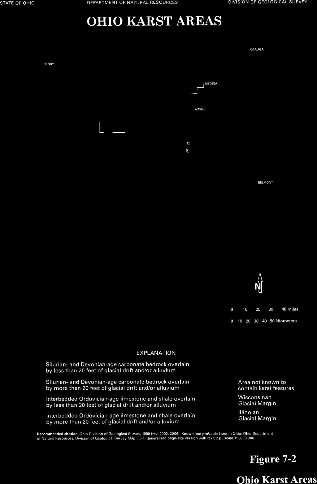
20 and pressure relief drains and a grout curtain were installed for FAD 1; surface fractures and discontinuities were cleaned and grouted as needed. The dam design included zones of various materials with an impervious clay core as the main cutoff material. Design stability, seepage and settlement analyses for FAD 2 were completed and presented in an ODNR Dam Safety submittal (SME, 2013). S&ME reported (AEP, 2012) that the MSE wall analyses indicate that the raising achieves the minimum required factors of safety against slope stability, bearing failure, sliding failure, and anticipated settlement within the tolerance of back-to-back MSE wall structure. Factors of safety reported in the ODNR submittal (SME, 2013) confirm this. As part of the FAD 2 raising, the stability of FAD 1 was re-evaluated using the higher FAR maximum operating water level of Elevation ft. The analyses showed acceptable factors of safety under the higher operating level for steady state and seismic loading conditions (AEP, 2012) Areas Susceptible to Liquefaction Due to the low seismicity of this region of Ohio, widespread liquefaction hazards within natural soil materials in the vicinity of the Site, including the CCR units, are not anticipated. A liquefaction potential assessment and liquefaction analysis of the fly ash for FAR II has not been performed as the reservoir is still an active disposal facility confined within a valley and by two dams. A liquefaction potential assessment review for the dams was provided. The assessment for dam FAD 2 reviewed the project specifications and fill compaction requirements and considered the dam embankment fills as non-liquefiable. The dam embankments are supported directly on bedrock and therefore non-liquefiable (S&ME 2015). Geosyntec concludes that liquefaction associated with either dam resulting from seismic design ground motions is not anticipated. AEP has completed the FAD 2 Initial Safety Factor Assessment for the dam prior to October 17, 2016 and has summarized the results in a report under CCR Rule Areas Susceptible to Mass Movements Observations of road cuts and former coal mine high-walls show there are potential areas of landslides and rock falls in the vicinity of FAR 1 RSW Landfill and FAR II. Areas where minespoil is present in slopes steepened by road building or other grading operations have shown evidence of slumping. There is no minespoil abutment slopes or foundations in minespoil material for the FAD 2. All minespoil in the vicinity, if present during dam construction, was excavated Areas Impacted By Natural and Human Induced Activities Human induced activities that could result in unstable areas in the vicinity of the site are generally limited to former or future surface and subsurface mining activities. FAR II is located in a region that was formerly stripped mined for Pittsburgh #8 coal. There were no underground mines within close CHE8126L\Cardinal_FAR II LOR Rpt _ August 2018
21 limits of FAD 2 that would affect dam stability. There is an abandoned underground mine (Mine JFN- 016) that is in close proximity or may be beneath the edge of the raised reservoir. This should not be a problem, but AEP should be aware of it and confirm if the location is correct. Documentation letters and location figures with respect to underground mines, air shafts, mine openings, and oil and gas wells are presented in the landfill PTI Volume 1 as part of the Narrative Report and Appendix B (AEP, 2005a). Figure 7-1, taken from PTI Volume 1 shows the locations of underground mines in the vicinity of the landfill and FAR II. Potential drawdown from nearby wells is not anticipated to have an adverse effect on the site due to the low yield and low capacity of these wells. Seismic activity is very low. No other naturally induced unstable conditions are anticipated Presence of Karst Terrain There are several limestone strata underlying the site, however, there are no observed or reported karst features evident. Further, Jefferson County is not located within the area mapped by the ODNR as a potential karst area in Ohio (ODNR, 2006). Figure 7-2 shows the potential karst locations within Ohio and those locations not known to contain any karst features Areas Susceptible to Coastal and River Erosion FAR 1 RSW Landfill and FAR II are not located in areas susceptible to coastal or river erosion as the Ohio River is approximately one mile away. Backup of streams and FAR II discharge flow would be expected during extreme or historic flooding. 7.3 Summary of Unstable Area Compliance Assessment The FAR II, including FAD 2, is compliant with the requirements of with respect to foundation and dike stability, dike liquefaction stability, mass movement, human induced activities, presence of karst terrain, and embankment erosion. Buckeye has indicated they will continue to reevaluate Structural Stability Assessments every 5 years and summarize results in periodic Structural Stability Assessment reports under CCR Rule CHE8126L\Cardinal_FAR II LOR Rpt _ August 2018
22 8. RECOMMENDATIONS Based on the compliance assessments provided herein, we have no recommendations. CHE8126L\Cardinal_FAR II LOR Rpt _ August 2018
23 9. CERTIFICATION BY A QUALIFIED PROFESSIONAL ENGINEER I certify that I have reviewed this Location Restriction Evaluation and based on the evaluations presented in this report, the existing Fly Ash Reservoir II at the Cardinal Operating Company s Cardinal Plant is, in my professional opinion, demonstrated to be in compliance with those EPA minimum location restriction requirements listed below. By means of this certification, I am stating that the demonstrations contained herein meet the requirements of: Fly Ash Reservoir II (including FAD 2) Section 40 CFR for Wetlands; Section 40 CFR for Fault Areas; Section 40 CFR for Seismic Impact Zones, and Section 40 CFR for Unstable Areas CHE8126L\Cardinal_FAR II LOR Rpt _ August 2018


24
25 FIGURES

26 Fly Ash Reservoir I / Residual Solid Waste Landfill PLANT AND CCR UNIT LOCATION MAP FIGURE OAK BROOK, IL AUGUST

27 FAR I RSW LANDFILL GENERAL DEVELOPMENT FIGURE 2-2 OAK BROOK, IL JULY 2016
28 RISE DAM SITE PLAN OAK BROOK, IL SEPTEMBER 2015 FIGURE 2-3
29 TYPICAL DAM CROSS SECTIONS / DETAILS FIGURE OAK BROOK, IL SEPTEMBER

30 Fly Ash Reservoir I / Residual Solid Waste Landfill Fly Ash Reservoir II FAR I RSW LANDFILL AND FAR II WETLAND FIGURE 4-1 AERIAL: 10/24/2014 USDA FSA OAK BROOK, IL JULY 2016


31 FAULT AREAS IN OHIO Path: U.S. GEOLOGICAL SURVEY. (2014). USGS INTERACTIVE FAULT MAP OF THE UNITED STATES, EARTHQUAKE HAZARDS PROGRAM, QUATERNARY FAULT AND FOLD DATABASE OF THE UNITED STATES. OAK BROOK, IL AUGUST 2015 FIGURE 5-1

32 DEAGGREGATION ANALYSIS FOR CARDINAL FAR I RSW LANDFILL FIGURE PROJECT OAK NO: BROOK, IL JULY

33 Cardinal Plant - FAR 1 RSW Landfill and FAR II FAR I RSW LANDFILL UNDERGROUND MINE LOCATIONS LEGEND: PERMITTED MINE ABANDON UNDERGROUND MINE FIGURE FAR I RWL N FAR II 7-1 AEP PROERTY OAK BROOK, IL JULY 2016
34
35 APPENDIX A REFERENCES
36 American Electric Power Service Corporation (AEP) and Geosyntec Consultants, Permit To Install Application Cardinal FAR 1 Residual Waste Landfill Facility Volume 1- Narrative Report, May 2006; for Geologic Setting Volume 2-Hydrogeological Investigation Report, October 2005 (AEP, 2005a). AEP and Geosyntec Consultants (2005b). Permit To Install Application Cardinal FAR 1 Residual Waste Landfill Facility Volume 4 Calculations. AEP and Geosyntec Consultants (2006). PTI Drawings for Cardinal FAR 1 RWL including 2008 PTI Modification, DWGs 2006, 2007 & AEP and S&ME, Inc. (2012). Dam Raising Design Summary, Cardinal Fly Ash Retention Pond II Wastewater PTI Application, April AEP (2014). Fall 2014 Groundwater Monitoring Data and Statistical Analyses for Cardinal Operating Company s Cardinal Waste Management Units, December 31, CHA (2009). CHA Companies, Assessment of Dam Safety Coal Combustion Surface Impoundment (Task 3) Final Report, December 9, COE (2013). Nationwide Permit No. 39 Approval Letter, Department of the Army, Pittsburgh District Corps of Engineers, December ODNR (2006). Ohio Department of Natural Resources Ohio Division of Geological Survey, Ohio Karst Areas, 1999 (Rev. 2006). ODNR (2011). Ohio Department of Natural Resources - Water Well Log Interactive Map. OEPA (2004). Ohio Environmental Protection Agency. Procedural and Technical Considerations for the Holocene Faults Location Restriction Demonstration. Policy DSIWM NOAA (2016). National Oceanic and Atmospheric Administration - Annual Climatological Summary, Station: Steubenville, OH US GHCND: USC S&ME, Inc. (2013). Revised Permit Application, Dam Raising Fly Ash Reservoir No. 2, January S&ME, Inc. (2015). Fly Ash Reservoir II Dam Initial Safety Factor Assessment, September 18, 2015.
37 USFS (2007). United States Fish and Wildlife Service - National Wetland Inventory Data (2007) for the FAR 1 RWL and FAR II areas plotted over United States Department of Agriculture (USDA) Aerial Photo (Oct. 10, 2014). USGS (2008). U.S. Geological Survey - National Seismic Hazard Analysis, U.S. Geological Survey. (2014). USGS Interactive Fault Map of the United States, Earthquake Hazards Program, Quaternary Fault and Fold Database of the United States.
LOCATION RESTRICTION EVALUATION
 Prepared for American Electric Power 1 Riverside Plaza Columbus, Ohio 43215 LOCATION RESTRICTION EVALUATION CARDINAL BOTTOM ASH POND BRILLIANT, OHIO Prepared by 1420 Kensington Road, Suite 103 Oak Brook,
ENGINEER S CERTIFICATION OF FAULT AREA DEMONSTRATION (40 CFR )
") PLATTE RIVER POWER AUTHORITY RAWHIDE ENERGY STATION BOTTOM ASH TRANSFER (BAT) IMPOUNDMENTS LARIMER COUNTY, CO ENGINEER S CERTIFICATION OF FAULT AREA DEMONSTRATION (40 CFR 257.62) FOR COAL COMBUSTION RESIDUALS
PLATTE RIVER POWER AUTHORITY RAWHIDE ENERGY STATION BOTTOM ASH TRANSFER (BAT) IMPOUNDMENTS LARIMER COUNTY, CO ENGINEER S CERTIFICATION OF FAULT AREA DEMONSTRATION (40 CFR 257.62) FOR COAL COMBUSTION RESIDUALS
STRUCTURAL STABILITY ASSESSMENT
 STRUCTURAL STABILITY ASSESSMENT CFR 257.73(d) Bottom Ash Pond Complex Cardinal Plant Brilliant, Ohio October, 2016 Prepared for: Cardinal Operating Company Cardinal Plant Brilliant, Ohio Prepared by: Geotechnical
CCR Surface Impoundment Location Restrictions Demonstration. MidAmerican Energy Company, Louisa Generating Station
 CCR Surface Impoundment Location Restrictions Demonstration MidAmerican Energy Company, Louisa Generating Station Final October 17, 2018 CCR Surface Impoundment Location Restrictions Demonstration Prepared
J.H. Campbell Generating Facility Pond A - Location Restriction Certification Report
 J.H. Campbell Generating Facility Pond A - Location Restriction Certification Report Pursuant to: 40 CFR 257.60 40 CFR 257.61 40 CFR 257.62 40 CFR 257.63 40 CFR 257.64 Submitted to: Consumers Energy Company
Big Rivers Electric Corporation Disposal of Coal Combustion Residuals (CCR) from Electric Utilities Final Rule CCR Impoundment Liner Assessment Report
 from Electric Utilities Final Rule CCR Impoundment Liner Assessment Report") Big Rivers Electric Corporation Disposal of Coal Combustion Residuals (CCR) from Electric Utilities Final Rule CCR Impoundment Liner Assessment Report CCR Surface Impoundment Information Name: Operator:
Big Rivers Electric Corporation Disposal of Coal Combustion Residuals (CCR) from Electric Utilities Final Rule CCR Impoundment Liner Assessment Report CCR Surface Impoundment Information Name: Operator:
HISTORY OF CONSTRUCTION FOR EXISTING CCR SURFACE IMPOUNDMENT PLANT GASTON ASH POND 40 CFR (c)(1)(i) (xii)
(1)(i) (xii)") HISTORY OF CONSTRUCTION FOR EXISTING CCR SURFACE IMPOUNDMENT PLANT GASTON ASH POND 40 CFR 257.73(c)(1)(i) (xii) (i) Site Name and Ownership Information: Site Name: E.C. Gaston Steam Plant Site Location:
HISTORY OF CONSTRUCTION FOR EXISTING CCR SURFACE IMPOUNDMENT PLANT GASTON ASH POND 40 CFR 257.73(c)(1)(i) (xii) (i) Site Name and Ownership Information: Site Name: E.C. Gaston Steam Plant Site Location:
INFLOW DESIGN FLOOD CONTROL SYSTEM PLAN 40 C.F.R. PART PLANT YATES ASH POND 2 (AP-2) GEORGIA POWER COMPANY
 GEORGIA POWER COMPANY") INFLOW DESIGN FLOOD CONTROL SYSTEM PLAN 40 C.F.R. PART 257.82 PLANT YATES ASH POND 2 (AP-2) GEORGIA POWER COMPANY EPA s Disposal of Coal Combustion Residuals from Electric Utilities Final Rule (40 C.F.R.
INFLOW DESIGN FLOOD CONTROL SYSTEM PLAN 40 C.F.R. PART 257.82 PLANT YATES ASH POND 2 (AP-2) GEORGIA POWER COMPANY EPA s Disposal of Coal Combustion Residuals from Electric Utilities Final Rule (40 C.F.R.
CHAPTER GEOLOGICALLY HAZARDOUS AREAS Applicability Regulations.
 CHAPTER 19.07 GEOLOGICALLY HAZARDOUS AREAS 19.07.010 Applicability. Geologically hazardous areas may pose a threat to the health and safety of citizens when incompatible development is sited in areas of
3.0 SUMMARY OF FINDINGS
 AECOM 500 W Jefferson St. Suite 1600 Louisville, KY 40202 www.aecom.com 502-569-2301 tel 502-569-2304 fax October 17, 2018 Big Rivers Electric Corporation Sebree Generating Station 9000 Highway 2096 Robards,
Slope Stability Evaluation Ground Anchor Construction Area White Point Landslide San Pedro District Los Angeles, California.
 Slope Stability Evaluation Ground Anchor Construction Area White Point Landslide San Pedro District Los Angeles, California Submitted To: Mr. Gene Edwards City of Los Angeles Department of Public Works
CCR Rule Annual Inspection Report (cont.) 2
 2") The inspection findings consisted of maintenance items and items that were not observed to be signs or potential signs of significant structural weakness. No deficiencies or disrupting conditions that
The inspection findings consisted of maintenance items and items that were not observed to be signs or potential signs of significant structural weakness. No deficiencies or disrupting conditions that
Location Restriction Demonstration
 Location Restriction Demonstration R.M. Heskett Station Coal Ash Landfill Prepared for Montana-Dakota Utilities Company October 2018 Minneapolis, MN, Bismarck, ND Location Restrictions Demonstration October
ENTERGY INDEPENDENCE PLANT EAST AND WEST RECYCLE PONDS DEMONSTRATION OF COMPLIANCE WITH EPA CCR RULE SITING CRITERIA , FAULT AREAS.
 ENTERGY INDEPENDENCE PLANT EAST AND WEST RECYCLE PONDS DEMONSTRATION OF COMPLIANCE WITH EPA CCR RULE SITING CRITERIA 257.62, FAULT AREAS Prepared for Entergy Arkansas, Inc. PO Box 551 Little Rock, AR 72203
ENVIRONMENTAL ENGINEERING LAND SURVEYING
 ENVIRONMENTL ENGINEERING LND SURVEYING Location Restrictions Otter Tail Power Company Coyote Station Introduction This report presents documentation and certification for the location standards for the
design, construction, operation, and maintenance of the BAP is consistent with recognized and generally accepted good engineering standards.
 design, construction, operation, and maintenance of the BAP is consistent with recognized and generally accepted good engineering standards. In addition to the field inspection, Associated Engineers, Inc.
ENTERGY WHITE BLUFF PLANT RECYCLE POND A AND RECYCLE POND B DEMONSTRATION OF COMPLIANCE WITH EPA CCR RULE SITING CRITERIA 257.
 ENTERGY WHITE BLUFF PLANT RECYCLE POND A AND RECYCLE POND B DEMONSTRATION OF COMPLIANCE WITH EPA CCR RULE SITING CRITERIA 257.62, FAULT AREAS Prepared for Entergy Arkansas, Inc. PO Box 551 Little Rock,
HISTORY OF CONSTRUCTION W.H. Sammis Coal Plant North and South Ponds Stratton, Ohio
 Prepared for: FirstEnergy Generation, LLC 76 South Main St Akron, OH 44308 HISTORY OF CONSTRUCTION Stratton, Ohio Prepared by: 10211 Wincopin Circle, Floor 4 Columbia, Maryland 21044 17 October 2016 pdf
CLECO POWER LLC DOLET HILLS POWER STATION
 SEPTEMBER 2018 CLECO POWER LLC DOLET HILLS POWER STATION SEISMIC IMPACT ZONES ASSESSMENT ASH BASIN No. 1 Prepared By: Providence Engineering and Environmental Group LLC 1201 Main Street Baton Rouge, Louisiana
IV. ENVIRONMENTAL IMPACT ANALYSIS G. GEOLOGY AND SOILS
 IV. ENVIRONMENTAL IMPACT ANALYSIS G. GEOLOGY AND SOILS The following section is a summary of the geotechnical report conducted for the proposed project. The Report of Geotechnical Investigation Proposed
HISTORY OF CONSTRUCTION FOR EXISTING CCR SURFACE IMPOUNDMENT PLANT GADSDEN ASH POND 40 CFR (c)(1)(i)-(xii)
(1)(i)-(xii)") HISTORY OF CONSTRUCTION FOR EXISTING CCR SURFACE IMPOUNDMENT PLANT GADSDEN ASH POND 40 CFR 257.73(c)(1)(i)-(xii) (i) Site Name and Ownership Information: Site Name: Site Location: Site Address: Gadsden
HISTORY OF CONSTRUCTION FOR EXISTING CCR SURFACE IMPOUNDMENT PLANT GADSDEN ASH POND 40 CFR 257.73(c)(1)(i)-(xii) (i) Site Name and Ownership Information: Site Name: Site Location: Site Address: Gadsden
Geophysical Methods for Screening and Investigating Utility Waste Landfill Sites in Karst Terrain
 Geophysical Methods for Screening and Investigating Utility Waste Landfill Sites in Karst Terrain Gary Pendergrass, PE, RG, F.NSPE Principal Geological Engineer Kansas City Geotechnical Conference 2017
Location Restrictions Certification Report NIPSCO Michigan City Generating Station Boiler Slag Pond
 Location Restrictions Certification Report NIPSCO Michigan City Generating Station Boiler Slag Pond Pursuant to: 40 CFR 257.60 40 CFR 257.61 40 CFR 257.62 40 CFR 257.63 40 CFR 257.64 Submitted to: Northern
Background. Valley fills Sites in the Area. Construction over Mine Spoil Fills
 Construction over Mine Spoil Fills Wayne A. Karem, PhD, PE, PG, D.GE 2014 KSPE Annual Conference Background Strip mining; mountaintop and contour mining Creates huge quantities of mine spoil The mine spoil
Setting MOUNTAIN HOUSE NEIGHBORHOODS I AND J INITIAL STUDY 5. ENVIRONMENTAL CHECKLIST 6. GEOLOGY AND SOILS. Issue
 Issue Less Than Significant or No Impact Potential Significant Impact Adequately Addressed in MEIR MEIR Required Additional Review: No Significant Impact Less Than Significant Impact Due to Mitigation
SLOPE STABILITY EVALUATION AND ACCEPTANCE STANDARDS
 INFORMATION BULLETIN / PUBLIC - BUILDING CODE REFERENCE NO.: LABC 7006.3, 7014.1 Effective: 01-01-2017 DOCUMENT NO.: P/BC 2017-049 Revised: 12-21-2016 Previously Issued As: P/BC 2014-049 SLOPE STABILITY
KANSAS GEOLOGICAL SURVEY Open File Report LAND SUBSIDENCE KIOWA COUNTY, KANSAS. May 2, 2007
 KANSAS GEOLOGICAL SURVEY Open File Report 2007-22 LAND SUBSIDENCE KIOWA COUNTY, KANSAS Prepared by Michael T. Dealy L.G., Manager, Wichita Operations SITE LOCATION The site was approximately four miles
Electronic Submission Format Guide Anthracite Preparation Plant Permit Application
 Electronic Submission Format Guide Anthracite Preparation Plant Permit Application Module 1: Application Section A through Section J, the Application Checklist, and all narrative responses Act 67 / 68
3.18 GEOLOGY AND SOILS
 3.18 GEOLOGY AND SOILS This section discusses geologic resource concerns as they relate to the environment, public safety, and project design both during construction and after completion of the project.
TAKING THE MYSTERY OUT OF USACE S ER DRILLING IN EARTH EMBANKMENT DAMS AND LEVEES
 TAKING THE MYSTERY OUT OF USACE S ER 1110-1-1807 DRILLING IN EARTH EMBANKMENT DAMS AND LEVEES 237 237 237 217 217 217 200 200 200 80 119 27 252 174.59 1 255 255 255 0 0 0 163 163 163 131 132 122 239 65
Surface Processes Focus on Mass Wasting (Chapter 10)
") Surface Processes Focus on Mass Wasting (Chapter 10) 1. What is the distinction between weathering, mass wasting, and erosion? 2. What is the controlling force in mass wasting? What force provides resistance?
Surface Processes Focus on Mass Wasting (Chapter 10) 1. What is the distinction between weathering, mass wasting, and erosion? 2. What is the controlling force in mass wasting? What force provides resistance?
SAN FRANCISCO DISTRICT INFORMATION REQUESTED FOR VERIFICATION OF CORPS JURISDICTION
 DEPARTMENT OF THE ARMY SAN FRANCISCO DISTRICT, U.S. ARMY CORPS OF ENGINEERS 1455 MARKET STREET SAN FRANCISCO, CALIFORNIA 94103-1398 SAN FRANCISCO DISTRICT INFORMATION REQUESTED FOR VERIFICATION OF CORPS
LOCATED IN INDIAN RIVER COUNTY PREPARED FOR S.J.R.W.M.D. AND F.W.C.D. DECEMBER, 2003 Updated 2007 Updated May 2014 PREPARED BY
 FELLSMERE WATER CONTROL DISTRICT EAST MASTER DRAINAGE PLAN AND STORMWATER HYDROLOGIC ANALYSIS OF THE GRAVITY DRAINAGE SYSTEM LOCATED BETWEEN THE EAST BOUNDARY, LATERAL U, THE MAIN CANAL, AND DITCH 24 LOCATED
THE MINISTRY OF ENERGY AND ENERGY INDUSTRIES MINERALS DIVISION MINE DESIGN TEMPLATE OPERATOR NAME: OPERATOR ADDRESS: PHONE NUMBER: FACSIMILE:
 THE MINISTRY OF ENERGY AND ENERGY INDUSTRIES MINERALS DIVISION MINE DESIGN TEMPLATE 1.0 GENERAL INFORMATION OPERATOR NAME: OPERATOR ADDRESS: PHONE NUMBER: FACSIMILE: NAME OF CONTACT: CELLULAR PHONE: EMAIL
Groundwater Hydrology
 EXERCISE 12 Groundwater Hydrology INTRODUCTION Groundwater is an important component of the hydrologic cycle. It feeds lakes, rivers, wetlands, and reservoirs; it supplies water for domestic, municipal,
4.5 GEOLOGY AND SOILS
 4.5 GEOLOGY AND SOILS This section addresses the project site geology and soils and analyzes potential changes that would result from development of the Wye Specific Plan project. 4.5.1 Environmental Setting
Converse Consultants Geotechnical Engineering, Environmental & Groundwater Science, Inspection & Testing Services
 Converse Consultants Geotechnical Engineering, Environmental & Groundwater Science, Inspection & Testing Services Ms. Rebecca Mitchell Mt. San Antonio College Facilities Planning & Management 1100 North
GEOLOGY, SOILS, AND SEISMICITY
 4.9 GEOLOGY, SOILS, AND SEISMICITY 4.9.1 Introduction Information about the geological conditions and seismic hazards in the study area was summarized in the FEIR, and was based on the Geotechnical Exploration
Mr. Michael Malone CPS Energy 145 Navarro Street San Antonio, Texas Project No
 January 17, 2018 Mr. Michael Malone 145 Navarro Street San Antonio, Texas 78205 Project No. 0337367 Environmental Resources Management CityCentre Four 840 West Sam Houston Pkwy N. Suite 600 Houston, Texas
3.0 SUMMARY OF FINDINGS
 AECOM 500 W Jefferson St. Suite 1600 Louisville, KY 40202 www.aecom.com 502-569-2301 tel 502-569-2304 fax October 17, 2018 Big Rivers Electric Corporation Sebree Generating Station 9000 Highway 2096 Robards,
Impact : Changes to Existing Topography (Less than Significant)
") 4.2 Land Resources 4.2.1 Alternative A Proposed Action Impact 4.2.1-1: Changes to Existing Topography (Less than Significant) Development of the project site would involve grading and other earthwork as
4.2 Land Resources 4.2.1 Alternative A Proposed Action Impact 4.2.1-1: Changes to Existing Topography (Less than Significant) Development of the project site would involve grading and other earthwork as
SLOPE STABILITY EVALUATION AND ACCEPTANCE STANDARDS
 INFORMATION BULLETIN / PUBLIC - BUILDING CODE REFERENCE NO.: LAMC 98.0508 Effective: 1-26-84 DOCUMENT NO. P/BC 2002-049 Revised: 11-1-02 Previously Issued As: RGA #1-84 SLOPE STABILITY EVALUATION AND ACCEPTANCE
Modeling Great Britain s Flood Defenses. Flood Defense in Great Britain. By Dr. Yizhong Qu
 Modeling Great Britain s Flood Defenses AIRCurrents Editor s note: AIR launched its Inland Flood Model for Great Britain in December 2008. The hazard module captures the physical processes of rainfall-runoff
THE NEED FOR AN ADDITIONAL SPILLWAY AT THE SANFORD DAM BOILING SPRING LAKES, NC. Presentation for The Brunswick County Commissioners April 20, 2015
 THE NEED FOR AN ADDITIONAL SPILLWAY AT THE SANFORD DAM BOILING SPRING LAKES, NC Presentation for The Brunswick County Commissioners April 20, 2015 The Sanford Dam Earth Dam constructed in 1961 Drainage
FRIENDS OF THE EEL RIVER
 FRIENDS OF THE EEL RIVER Working for the recovery of our Wild & Scenic River, its fisheries and communities. Frank Blackett, Regional Engineer Office of Energy Projects Division of Dam Safety and Inspections
LIQUEFACTION OF EARTH EMBANKMENT DAMS TWO CASE HISTORIES: (1) LIQUEFACTION OF THE EMBANKMENT SOILS, AND (2) LIQUEFACTION OF THE FOUNDATIONS SOILS
 LIQUEFACTION OF THE EMBANKMENT SOILS, AND (2) LIQUEFACTION OF THE FOUNDATIONS SOILS") LIQUEFACTION OF EARTH EMBANKMENT DAMS TWO CASE HISTORIES: (1) LIQUEFACTION OF THE EMBANKMENT SOILS, AND (2) LIQUEFACTION OF THE FOUNDATIONS SOILS Antonio Fernandez, Ph.D. 1 ABSTRACT Paul C. Rizzo Associates,
LIQUEFACTION OF EARTH EMBANKMENT DAMS TWO CASE HISTORIES: (1) LIQUEFACTION OF THE EMBANKMENT SOILS, AND (2) LIQUEFACTION OF THE FOUNDATIONS SOILS Antonio Fernandez, Ph.D. 1 ABSTRACT Paul C. Rizzo Associates,
CCR Rule Compliance: Innovative Use of Geophysics to Certify Landfill Stability and Site Groundwater Monitoring Wells
 CCR Rule Compliance: Innovative Use of Geophysics to Certify Landfill Stability and Site Groundwater Monitoring Wells Gary Pendergrass, PE, RG Principal Geological Engineer Missouri Waste Control Coalition
GEOLOGY AND SOILS. This chapter summarizes geologic and geotechnical aspects of the site as they relate to the Project.
 9 GEOLOGY AND SOILS INTRODUCTION This chapter summarizes geologic and geotechnical aspects of the site as they relate to the Project. This chapter utilizes information from the following reports prepared
Use of Instrumented Test Fill to Assess Static Liquefaction of Impounded Fly Ash
 2013 World of Coal Ash (WOCA) Conference - April 22-25, 2013 in Lexington, KY http://www.flyash.info/ Use of Instrumented Test Fill to Assess Static Liquefaction of Impounded Fly Ash Omer Bozok 1, Paul
NEWS RELEASE UNDER SECTION 404 OF THE CLEAN WATER ACT (33 USC 1344) ACTION NUMBER SPA ABQ
 ACTION NUMBER SPA ABQ") PUBLIC NOTICE Public Notice Issue Date: //6/07 Albuquerque District Comments due: /6/08 NEWS RELEASE UNDER SECTION 0 OF THE CLEAN WATER ACT ( USC ) ACTION NUMBER SPA-06-00-ABQ BANK STABILIZATION ALONG
PUBLIC NOTICE Public Notice Issue Date: //6/07 Albuquerque District Comments due: /6/08 NEWS RELEASE UNDER SECTION 0 OF THE CLEAN WATER ACT ( USC ) ACTION NUMBER SPA-06-00-ABQ BANK STABILIZATION ALONG
Appendix E Guidance for Shallow Flooding Analyses and Mapping
 Appendix E Guidance for Shallow Flooding Analyses and Mapping E.1 Introduction Different types of shallow flooding commonly occur throughout the United States. Types of flows that result in shallow flooding
Sacramento Modesto Roseville Pleasanton September 19, 2013 Marcia Medina GHD Inc. 417 Montgomery Street, Suite 700 San Francisco, CA Subject: GE
 Sacramento Modesto Roseville Pleasanton September 19, 2013 Marcia Medina GHD Inc. 417 Montgomery Street, Suite 700 San Francisco, CA 94104 Subject: GEOTECHNICAL REPORT AMENDMENT Stonybrook Creek Crossings
PENNSYLVANIA DEPARTMENT OF TRANSPORTATION ENGINEERING DISTRICT 3-0
 PENNSYLVANIA DEPARTMENT OF TRANSPORTATION ENGINEERING DISTRICT 3-0 LYCOMING COUNTY S.R.15, SECTION C41 FINAL HYDROLOGIC AND HYDRAULIC REPORT STEAM VALLEY RUN STREAM RELOCATION DATE: June, 2006 REVISED:
Remedial Program. GE Hudson Falls Plant Site. GE Hudson Falls Plant Site. TDCS Status
 Updates on Remedial Programs at the GE Hudson Falls Plant Site and GE Fort Edward Plant Site GE Hudson Falls USEPA Community Advisory Group Meeting September 11, 2008 GE Fort Edward Division of Environmental
Electronic Submission Format Guide Bituminous Coal Surface Mine Permit Application (5600-PM-BMP0311)
") Electronic Submission Format Guide Bituminous Coal Surface Mine Permit Application (5600-PM-BMP0311) Module 1: Application Section A through Section J, the Application Checklist, and all narrative responses.
Electronic Submission Format Guide Bituminous Coal Surface Mine Permit Application (5600-PM-BMP0311) Module 1: Application Section A through Section J, the Application Checklist, and all narrative responses.
Downtown Anchorage Seismic Risk Assessment & Land Use Regulations to Mitigate Seismic Risk
 Prepared for: The Municipality of Anchorage Planning Department and the Geotechnical Advisory Commission Downtown Anchorage Seismic Risk Assessment & Land Use Regulations to Mitigate Seismic Risk Prepared
REDWOOD VALLEY SUBAREA
 Independent Science Review Panel Conceptual Model of Watershed Hydrology, Surface Water and Groundwater Interactions and Stream Ecology for the Russian River Watershed Appendices A-1 APPENDIX A A-2 REDWOOD
Chapter 7 Mudflow Analysis
 Chapter 7 Mudflow Analysis 7.0 Introduction This chapter provides information on the potential and magnitude of mud floods and mudflows that may develop in Aspen due to rainfall events, snowmelt, or rain
4.9 GEOLOGY AND SOILS
 4.9 GEOLOGY AND SOILS 4.9.1 EXISTING CONDITIONS TOPOGRAPHY AND RELIEF Zone 40 is located in the central portion of Sacramento County. The topography of the county is represented by three physiographic
9/23/2013. Introduction CHAPTER 7 SLOPE PROCESSES, LANDSLIDES, AND SUBSIDENCE. Case History: La Conchita Landslide
 Introduction CHAPTER 7 SLOPE PROCESSES, LANDSLIDES, AND SUBSIDENCE Landslide and other ground failures posting substantial damage and loss of life In U.S., average 25 50 deaths; damage more than $3.5 billion
November 20, 2003 Project
 November 20, 2003 Project 032810 1021 Main Street Winchester, MA 01890-1970 781.721.4000 781.721.4073 fax Mr. Bobby Van Cleave Geotechnical Engineer Little Rock District Federal Building, 7th Floor 700
UPPER COSUMNES RIVER FLOOD MAPPING
 UPPER COSUMNES RIVER FLOOD MAPPING DRAFT BASIC DATA NARRATIVE FLOOD INSURANCE STUDY SACRAMENTO COUTY, CALIFORNIA Community No. 060262 November 2008 Prepared By: CIVIL ENGINEERING SOLUTIONS, INC. 1325 Howe
 12 10 8 6 4 2 0 40-50 50-60 60-70 70-80 80-90 90-100 Fresh Water What we will cover The Hydrologic Cycle River systems Floods Groundwater Caves and Karst Topography Hot springs Distribution of water in
Pierce County Department of Planning and Land Services Development Engineering Section
 Page 1 of 7 Pierce County Department of Planning and Land Services Development Engineering Section PROJECT NAME: DATE: APPLICATION NO.: PCDE NO.: LANDSLIDE HAZARD AREA (LHA) GEOLOGICAL ASSESSMENT REPORT
Association of Environmental & Engineering Geologists (AEG) To join AEG: Student membership is Free! Ask about our scholarships.
 To join AEG: Student membership is Free! Ask about our scholarships.") Association of Environmental & Engineering Geologists (AEG) To join AEG: www.aegweb.org/join Student membership is Free! Ask about our scholarships. What is the Association of Environmental & Engineering
Association of Environmental & Engineering Geologists (AEG) To join AEG: www.aegweb.org/join Student membership is Free! Ask about our scholarships. What is the Association of Environmental & Engineering
Chapter 7 Mudflow Analysis
 Chapter 7 Mudflow Analysis 7.0 Introduction This chapter provides information on the potential and magnitude of mud floods and mudflows that may develop in Aspen due to rainfall events, snowmelt, or rain
9/13/2011 CHAPTER 9 AND SUBSIDENCE. Case History: La Conchita Landslide. Introduction
 CHAPTER 9 SLOPE PROCESSES, LANDSLIDES, AND SUBSIDENCE Case History: La Conchita Landslide La Conchita: small coastal community 80 km (50 mi) northwest of Los Angeles Landslide occurred on January 10, 2005
Electronic Submission Format Guide Large Noncoal (Industrial Minerals) Mine Permit Application (5600-PM-BMP0315)
 Mine Permit Application (5600-PM-BMP0315)") Electronic Submission Format Guide Large Noncoal (Industrial Minerals) Mine Permit Application (5600-PM-BMP0315) Module 1: Application Section A through Section I, the Application Checklist, and all narrative
Electronic Submission Format Guide Large Noncoal (Industrial Minerals) Mine Permit Application (5600-PM-BMP0315) Module 1: Application Section A through Section I, the Application Checklist, and all narrative
Numerical analysis of effect of mitigation measures on seismic performance of a liquefiable tailings dam foundation
 Numerical analysis of effect of mitigation measures on seismic performance of a liquefiable tailings dam foundation Yong-Beom Lee, Jorge Castillo Ausenco, USA Aurelian C. Trandafir Fugro GeoConsulting
Guidelines for Site-Specific Seismic Hazard Reports for Essential and Hazardous Facilities and Major and Special-Occupancy Structures in Oregon
 Guidelines for Site-Specific Seismic Hazard Reports for Essential and Hazardous Facilities and Major and Special-Occupancy Structures in Oregon By the Oregon Board of Geologist Examiners and the Oregon
Converse Consultants Geotechnical Engineering, Environmental & Groundwater Science, Inspection & Testing Services
 Converse Consultants Geotechnical Engineering, Environmental & Groundwater Science, Inspection & Testing Services July 27, 2017 Ms. Rebecca Mitchell Mt. San Antonio College Facilities Planning & Management
Sediment Trap. A temporary runoff containment area, which promotes sedimentation prior to discharge of the runoff through a stabilized spillway.
 Sediment Trap SC-15 Source: Caltrans Construction Site Best Management Practices Manual, 2003. Description A temporary runoff containment area, which promotes sedimentation prior to discharge of the runoff
Roy Pyle March 24, 2017 Chief Facilities Planner Contra Costa Community College District 500 North Court Street Martinez, CA 94533
 State of California Natural Resources Agency Edmund G. Brown Jr., Governor Department of Conservation John G. Parrish, Ph.D., State Geologist California Geological Survey 801 K Street MS 12-31 Sacramento,
GOAL 7 AREAS SUBJECT TO NATURAL DISASTERS AND HAZARDS. To protect life and property from natural disasters and hazards.
 GOAL 7 AREAS SUBJECT TO NATURAL DISASTERS AND HAZARDS A. GOALS: To protect life and property from natural disasters and hazards. B. POLICIES: 1. Floodplains shall be maintained as natural drainage-ways.
Emergency Action Plan (EAP) Tata Pond Dam
 Tata Pond Dam") For Official Use Only Not for Public Distribution 02/03/16 Emergency Action Plan (EAP) Tata Pond Dam State of Connecticut Dam ID: 0000 Town or City, County, Connecticut Name of Dam Owner Dam Hazard Classification
For Official Use Only Not for Public Distribution 02/03/16 Emergency Action Plan (EAP) Tata Pond Dam State of Connecticut Dam ID: 0000 Town or City, County, Connecticut Name of Dam Owner Dam Hazard Classification
GEOTECHNICAL ENGINEERING INVESTIGATION HANDBOOK Second Edition
 GEOTECHNICAL ENGINEERING INVESTIGATION HANDBOOK Second Edition Roy E. Hunt Taylor & Francis Taylor & Francis Croup Boca Raton London New York Singapore A CRC title, part of the Taylor & Francis imprint,
Rock & Aggregate Drop Inlet Protection
 Rock & Aggregate Drop Inlet Protection SEDIMENT CONTROL TECHNIQUE Type 1 System Sheet Flow Sandy Soils Type 2 System [1] Concentrated Flow Clayey Soils Type 3 System Supplementary Trap Dispersive Soils
Rogun Hydropower Project
 Rogun Hydropower Project Dam site Geological investigations in the Downstream Right Bank Ascencio Lara Coyne et Bellier Almaty, 11-12 February 2013 Objectives of the presentation As the stability conditions
June 9, R. D. Cook, P.Eng. Soils Engineer Special Services Western Region PUBLIC WORKS CANADA WESTERN REGION REPORT ON
 PUBLIC WORKS CANADA WESTERN REGION REPORT ON GEOTECHNICAL INVESTIGATION PROPOSED MARTIN RIVER BRIDGE MILE 306.7 MACKENZIE HIGHWAY Submitted by : R. D. Cook, P.Eng. Soils Engineer Special Services Western
Coal Combustion Residuals Unit Inflow Design Flood Control System Plan
 Coal Combustion Residuals Unit Inflow Design Flood Control System Plan Virginia Electric and Power Company Chesterfield Power Station Upper (East) Pond Chesterfield County, Virginia GAI Project Number:
This report was prepared by Klohn Crippen Consultants Ltd. for Alberta Transportation Central Region under Contract No. CE053/2000.
 Alberta Transportation Central Region #401, 4902 51 Street Red Deer, Alberta T4N 6K8 June 7, 2002 Mr. Melvin Mayfield, P.Eng. Project Engineer Dear Mr. Mayfield: Central Region Landslide Assessment Site
Illinois Drought Update, December 1, 2005 DROUGHT RESPONSE TASK FORCE Illinois State Water Survey, Department of Natural Resources
 Illinois Drought Update, December 1, 2005 DROUGHT RESPONSE TASK FORCE Illinois State Water Survey, Department of Natural Resources For more drought information please go to http://www.sws.uiuc.edu/. SUMMARY.
URBAN HYDROLOGY: WATER IN THE CITY OF TSHWANE Plant Sciences Auditorium, University of Pretoria January 2014 URBAN HYDROGEOLOGY
 URBAN HYDROLOGY: WATER IN THE CITY OF TSHWANE Plant Sciences Auditorium, University of Pretoria 23 24 January 2014 URBAN HYDROGEOLOGY MATTHYS A. DIPPENAAR DEPARTMENT GEOLOGY, UNIVERSITY OF PRETORIA HYDROGEOLOGY
Prof. Stephen A. Nelson EENS 111. Groundwater
 Page 1 of 8 Prof. Stephen A. Nelson EENS 111 Tulane University Physical Geology This page last updated on 20-Oct-2003 is water that exists in the pore spaces and fractures in rock and sediment beneath
SLOPE PROCESSES, LANDSLIDES, AND SUBSIDENCE
 CHAPTER 9 SLOPE PROCESSES, LANDSLIDES, AND SUBSIDENCE La Conchita slide January 10, 2005 Triggered by heavy rainfall, reactivation along an older landslide surface (35,000 years ago, 6000 years ago, and
NOA ASSESSMENT HARRIS QUARRY MENDOCINO COUNTY, CALIFORNIA TABLE OF CONTENTS
 NOA ASSESSMENT HARRIS QUARRY MENDOCINO COUNTY, CALIFORNIA TABLE OF CONTENTS Introduction... 1 Scope of Services... 1 Project Location and Description... 1 Geologic Setting... 1 Regional Geology... 1 Site
IV. ENVIRONMENTAL IMPACT ANALYSIS E. GEOLOGY AND SOILS
 IV. ENVIRONMENTAL IMPACT ANALYSIS E. GEOLOGY AND SOILS The following section is a summary of the geotechnical report conducted for the Proposed Project. The Geotechnical Engineering Investigation (the
NORTHUMBERLAND COUNTY, PA
 QUAKER RUN Stream and Wetland Restoration As-Built Completion Report and First Year Monitoring Data Coal Township NORTHUMBERLAND COUNTY, PA Upstream Before Upstream After Prepared for: COAL TOWNSHIP 805
IV. ENVIRONMENTAL IMPACT ANALYSIS E. GEOLOGY/SOILS
 IV. ENVIRONMENTAL IMPACT ANALYSIS E. GEOLOGY/SOILS Except where otherwise noted, the following Section is based on the Preliminary Geotechnical Investigation, Proposed Medical Office Buildings and Mixed-Use
Review of Vermont Yankee Thermal Discharge Permit Requirements and Analysis of Connecticut River Water Temperature and Flow
 Review of Vermont Yankee Thermal Discharge Permit Requirements and Analysis of Connecticut River Water Temperature and Flow August 17, 2012 Prepared by: Ken Hickey Peter Shanahan, Ph.D., P.E. 481 Great
Amistad Dam Investigation and Oversight: Karst- Founded Dam on the USA-Mexico Border
 Amistad Dam Investigation and Oversight: Karst- Founded Dam on the USA-Mexico Border Brook Brosi, CPG, PG USACE Lisa Nowicki Perks, PG USACE Kimberly Heenan, PE AECOM US Army Corps of Engineers BUILDING
APPROVED JURISDICTIONAL DETERMINATION FORM U.S. Army Corps of Engineers
 APPROVED JURISDICTIONAL DETERMINATION FORM U.S. Army Corps of Engineers SECTION I: BACKGROUND INFORMATION A. REPORT COMPLETION DATE FOR APPROVED JURISDICTIONAL DETERMINATION (JD): November 3, 06 B. DISTRICT
[1] Performance of the sediment trap depends on the type of outlet structure and the settling pond surface area.
![[1] Performance of the sediment trap depends on the type of outlet structure and the settling pond surface area.](/thumbs/76/74245181.jpg "[1] Performance of the sediment trap depends on the type of outlet structure and the settling pond surface area.") Sediment Trench SEDIMENT CONTROL TECHNIQUE Type 1 System Sheet Flow Sandy Soils Type 2 System [1] Concentrated Flow Clayey Soils Type 3 System [1] Supplementary Trap Dispersive Soils [1] Performance of
Sediment Trench SEDIMENT CONTROL TECHNIQUE Type 1 System Sheet Flow Sandy Soils Type 2 System [1] Concentrated Flow Clayey Soils Type 3 System [1] Supplementary Trap Dispersive Soils [1] Performance of
NUCLEAR POWER PLANT SITE SELECTION
 NUCLEAR POWER PLANT SITE SELECTION ABDELATY B. SALMAN Ex-Chairman Nuclear Materials Authority, Cairo, Egypt I. Introduction The aim of this article is to present the requirements and characteristics for
2. Initial Summary of Preliminary Expert Opinion of Converse and Psomas Reports
 UNITED WALNUT TAXPAYERS PRELIMINARY REVIEW OF NEGATIVE GEOTECHNICAL AND GEOLOGICAL ASPECTS OF CONSTRUCTING EARTHFILL PAD FOR A SOLAR FARM ON THE WEST PARCEL - DRAFT 1. Introduction A licensed Engineering
Template for Sediment and Erosion Control Plan General Instructions. Section Instructions
 Template for Sediment and Erosion Control Plan General Instructions Introduction: Soil erosion and sediment deposition from farmlands can contribute to degraded surface water quality. Sediment delivery
6.1 Water. The Water Cycle
 6.1 Water The Water Cycle Water constantly moves among the oceans, the atmosphere, the solid Earth, and the biosphere. This unending circulation of Earth s water supply is the water cycle. The Water Cycle
Prof. B V S Viswanadham, Department of Civil Engineering, IIT Bombay
 19 Module 5: Lecture -1 on Stability of Slopes Contents Stability analysis of a slope and finding critical slip surface; Sudden Draw down condition, effective stress and total stress analysis; Seismic
Prentice Hall EARTH SCIENCE
 Prentice Hall EARTH SCIENCE Tarbuck Lutgens Running Water and Groundwater Running Water The Water Cycle Water constantly moves among the oceans, the atmosphere, the solid Earth, and the biosphere. This
Chapter 3 Erosion in the Las Vegas Wash
 Chapter 3 Erosion in the Las Vegas Wash Introduction As described in Chapter 1, the Las Vegas Wash (Wash) has experienced considerable change as a result of development of the Las Vegas Valley (Valley).