CNT-reinforced polymer nanocomposite by molecular dynamics simulations
|
|
|
- Clementine Fletcher
- 6 years ago
- Views:
Transcription

1 Purdue University Purdue e-pubs Open Access Dissertations Theses and Dissertations Fall 2014 CNT-reinforced polymer nanocomposite by molecular dynamics simulations Yaeji Kim Purdue University Follow this and additional works at: Part of the Materials Science and Engineering Commons Recommended Citation Kim, Yaeji, "CNT-reinforced polymer nanocomposite by molecular dynamics simulations" (2014). Open Access Dissertations This document has been made available through Purdue e-pubs, a service of the Purdue University Libraries. Please contact epubs@purdue.edu for additional information.
2
3
4 CNT-REINFORCED POLYMER NANOCOMPOSITE BY MOLECULAR DYNAMICS SIMULATIONS A Dissertation Submitted to the Faculty of Purdue University by Yae Ji Kim In Partial Fulfillment of the Requirements for the Degree of Doctor of Philosophy December 2014 Purdue University West Lafayette, Indiana
5 ii TABLE OF CONTENTS Page LIST OF TABLES..iv LIST OF FIGURES. v ABSTRACT..vii CHAPTER 1. INTRODUCTION...1 CHAPTER 2. MATERIALS AND METHODS Molecular Dynamics Why Molecular Dynamics? Classical Equations of Motion Interatomic Potential for Polymer Steered Molecular Dynamics Generation of Amorphous Structure of Polymer Analyzing Molecular Dynamics Molecular Structure of Carbon Nanotubes 13 CHAPTER 3. STRUCTURAL PROPERTIES OF PMMA SLAB: ROLE OF ANNEALING CONDITION Motivation Computational Details Generation of Slabs and Their Annealing Slab Formation and Relaxation Slab Annealing...20
6 iii 3.4. Molecular Structures Slab Properties Density Profiles Surface Energy Conclusion 35 CHAPTER 4. INTERACTION OF CNTS WITH POLYMER MATRIX CNT Interaction with PMMA Surfaces and Diffusion Displacement of CNTs Prediction of CNTs Steered Interaction with PMMA Surfaces and Viscosity Effective CNT-CNT Interactions Through Polymer Matrix CNT-CNT Interaction Through the Polymer Formation of Discrete Adsorption Layers Many Body Effects in CNT-CNT Interactions.51 CHAPTER 5. MECHANICAL RESPONSE OF CNT-POLYMER COMPOSITES Effect of CNT on the Molecular Structure of Polymer Matrix Elastic Response of CNT Polymer Composition and Local Property..61 CHAPTER 6. CONCLUSIONS...63 LIST OF REFERENCES..65 VITA.70
7 iv LIST OF TABLES Table... Page Table 3.1 Thermo-mechanical history..22 Table 3.2. Bond-Orientational order parameter analysis..28 Table 3.3. Slab size and predicted properties...34
8 v LIST OF FIGURES Figure... Page Figure 1.1 Ashby Charts, (a) Young s modulus vs Density, (b) Strength- Density 2 Figure 3.1 Atomic snapshots from the MD simulations used to create the PMMA slabs at various strain levels. Total deformation is 600% over a time of 400 ps 18 Figure 3.2 Stress-strain curves during the deformation and thermalization..19 Figure 3.3 Atomistic snapshots of the PMMA slab (a) after deformation and thermalization at T=600 K for 400 ps, and (b) after annealing to T=300 K using NPT MD with a cooling rate of25 K/ 100 ps (c) after annealing to T=300 K using NVT MD with a cooling rate of 10 K/ 200 ps Figure 3.4 Transverse cell length change during annealing Figure 3.5 Radius of gyration during creating PMMA slab and atomistic snap shots during deformation with six chains singled out...24 Figure 3.6 Radius of gyration of slabs and bulks at T= 600 K. 25 Figure 3.7 Radius of gyration of slabs and bulks at T=300 K..26 Figure 3.8 Density profiles of slabs Figure 3.9 Surface energy vs. temperature during annealing for slabs of 57,680 atoms with NPT 25 K/ 100 ps and NVT 10 K/ 200 ps annealing Figure 4.1 A snapshot of computational model for PMMA/CNT composite 38 Figure 4.2 Displacements of CNTs into PMMA depending on the time evolution during thermailzation Figure 4.3 Longitudinal and transeverse displacements of CNTs in PMMA slab depending on the time evolution during thermailzation 41
9 vi Figure... Page Figure 4.4 CNT mobility in longitudinal and transverse in plane directions.43 Figure 4.5 Viscous flow analysis of molten PMMA at 600K Figure 4.6 Snapshot of computational model for PE /CNTcomposite.. 46 Figure 4.7 (a) Force on CNT as a function of distance between two CNTs, (b) CNT CNT distances convergence as a function of time at 400K Figure 4.8 Densification of adsorption layers at 400 K. 50 Figure 4.9 Densification of adsorption layers at 50 K...51 Figure 4.10 Atomistic snapshot of 3CNT embedded PE compsoites Figure 4.11 Three body interactions effects in CNT-CNT composite..53 Figure Three-body Force analysis cartoon...54 Figure 4.13 Atomistic snapshot of 3CNT embedded PE composites Figure 4.14 Hexagonal-alignment CNT interactions effects in CNT-CNT composite.56 Figure 5.1 Orientation order parameter with various CNT distances at 400K..59 Figure 5.2 Orientation order parameter with various CNT distances at 50K 60 Figure 5.3 Local stiffness of polymer respect to the distance from center of CNT at 50K Figure 5.4 Orientation order parmeter change after deformation
10 vii ABSTRACT Kim,Yae ji., Ph.D., Purdue University, December PMMA slab and CNT-reinforced polymer nanocomposite by Molecular Dynacmis Simulations. Major Professor: Alejandro Strachan, School of Materials Engineering. Polymer matrix composites reinforced with carbon nanotubes (CNTs) have received significant attention due to their potential for exceptional mechanical, electrical, thermal and optical properties. The enhancement of ultimate mechanical properties of CNT reinforced polymer composites is governed not just by the properties of the two phases but by dispersion of the CNTs, interactions in the interfacial region and local molecular changes in polymer due to the vicinity of the CNTs. Strong adhesive interactions between the matrix and CNT leads to good compatibility preventing the aggregation of the reinforcements and results in optimal mechanical response. Even though significant efforts have been devoted to the understanding of fundamental issues regarding the synthesis and properties of these materials, a predictive understanding of the interaction between CNTs and polymer matrices is lacking resulting in sub-optimal properties. We use molecular dynamics simulations to characterize the effective CNT-CNT and CNT-matrix interactions as well as mechanical response of CNT-reinforced composite. We find that the short-range CNT-CNT interaction is governed by the perturbations caused on the polymer local structures by the CNTs. Interestingly, we find
11 that these interactions are not pairwise additive and characterize the many body effects. We also quantify how these short-range perturbations of the polymer structure affect their local mechanical response and that of the composite as a whole. We find the local stiff of the polymer near the CNTs is 30 times higher than that of the bulk. viii Our study provides key insight and parameters into the basis of interactions in CNT reinforced polymer nanocomposites that could help the design of optimized materials.
12 1 CHAPTER 1. INTRODUCTION Since the invention of carbon nanotubes for two decades ago by Iijima [1], it has been used in wide range of fundamental science activities and application due to exclusive superlative mechanical properties[2] as well as electrical[3] and thermal properties[4]. In needs of new material or substitution for light weight and superior mechanical properties in industries fields such as nanostructures, aerospace and electronics, CNT has been the candidates as most ideal reinforcement for composite. The exceptional properties such as high aspect ratio, and conductivity, mechanical strength makes CNT-reinforced composite to functionalize as thermally conductive composite, conductive composite having exceedingly low electrical low percolation thresholds [5,6]. However their unique mechanical properties, extremely high Young s modulus of 1Tpa [7], high strength of 63Gpa [8] makes significant improvement for mechanical properties of composite as ultimate mechanical filler. Also the nano-size reinforcement in nanocomposite changes properties of matrix differentiating from macro-scale composites due to the size of reinforcement domain size which is comparable with the matrix molecule s physical length scale.
 Young s modulus vs")
![Density, (b) Strength- Density [56].](/docs-images/80/80662182/images/13-1.jpg "Taken from http://www-materials.eng.cam.")
13 2 (a) (b) Fig 1.1 Ashby Charts, (a) Young s modulus vs Density, (b) Strength- Density [56]. Taken from
14 3 Although enormous number of papers reported exceptional results on properties enhancement in CNT-polymer nanocomposite, the lack of fundamental understanding of some of issues in characterization, synthesis prevent realization of carbon nanotube reinforced composite in applications. Some of issues include the understanding of the interface micromechanics, dispersion, surface adhesion and load transfer between the CNT and polymer is still in the absence but these are very crucial because these variables result in significant difference in mechanical properties such as strength and stiffness of nanocomposite. Depending on the processing condition such as temperature, catalyst, type of synthesis and interface condition bonding between CNT and matrix are generated. Generally there are two types of interface in terms of bonding: perfectly bonded with chemical bonding, particularly covalent bonding and imperfectly bonded with noncovalent bonding consisted with van der Waals interaction, electrostatics force. Still there are many arguments on the dominant factor on governing the strength of interface and hence the mechanics involves the CNT/polymer interface, ability of carrying of stress. Mechanical properties improvement by stress transferring in interfacial region of CNT reinforced composite has been studied intensively in experimentally and computationally [9-11]. However in experimentally investigating the stress transferring mechanism relating interface is so convoluted by manipulating, processing, measurement in small scale, so unable to explain clearly the role of interface. Computational method provides alternative solution to the limitation of experiment study. Atomistic simulations are playing an increasingly important role in understanding the structure and physics of polymers and interactions of CNT reinforced composite. For example, molecular
15 4 dynamics simulations provided insight into the role of size on the mechanical response of nanoscale polymer samples [12] and contributed to the characterization of the heterogeneous distribution of local dynamic mechanical properties of glassy polymer thin films [13]. These simulations also helped establish firm relationships between molecular structure and properties; for example, polymer chain orientation effects on anisotropic plasticity [14] have been studied and so has the effect of entanglement density on strain hardening of polymer glasses [15]. While restricted to relatively small sizes and short timescales these atomistic level simulations provide insight and quantitative information that can be used in continuum level models capable of achieving scales of interest in most real applications [42]. We use molecular dynamics simulations to characterize the effective interaction in CNT-reinforced polymer nanocomposite: CNT interaction with polymer in surface and CNT-CNT interaction via the polymer matrix that govern their aggregation. We find that the short-range interaction is govern by the interactions between the perturbations the CNTs cause on the polymer density. We also quantify how these short range perturbation of the polymer structure affects their local mechanical response and that of the composite as a whole. In this thesis, materials and methodology used for CNT- reinforced polymer nanocomposite including Molecular Dynamics and generation of polymer are firstly introduced in Chapter 2. Chapter 3 presented structural properties of PMMA slab which is used as composite matrix with description of role of annealing. The interaction of CNT with polymer matrices will be discussed including CNT interaction with PMMA surface and diffusion and effective CNT-CNT interaction through the polymer in Chapter 4. In
16 5 Chapter 5, mechanical response of CNT-polymer composite related interactions in interfacial region covered in Chapter 4 is investigated. Finally Chapter 6 is dedicated to provide a summary and conclusion of this study.
17 6 CHAPTER 2. MATERIALS AND METHODS 2.1. Molecular Dynamics Why Molecular Dynamics? Depending on the problem and spatial and temporal scales of interest, there is wide range scale of material modeling exist from Quantum mechanics simulations to continuum simulations. Mesoscale simulation is useful in accurate macroscopic properties prediction in μm in size or μs in time. One possibility in mesodynamics is to perform coarse grain simulations which describe particles or grains to represent group of atoms. With significantly reduced cost, accurately properties predictions of materials such as pontial energy, density and bulk modulus are achievable with reliable mesoparticles description force field. These extension of scale in time and length are caused by using of mesoscale dynamics larger time steps for the integration of the motion of the mesoparticles because of the lower frequency vibrational modes of mesoparticles [1]. However not all the properties are computed reliably and accurately using continuum modeling. In continuum simulation atomic level description are under approximation such as surface and interfacial process, atomic level chemistry, interactions and defect nucleation etc. Thus, depending on the properties of interest, molecular dynamics or first
18 7 principle simulations are rather ideally suited to investigate nanoscale materials properties. Molecular dynamics (MD) is an atomistic scale simulation which describes interaction between the atoms by interatomic potentials. In MD method, electron effects are averaged out and time evolution of atomic position and velocities are computed from Newton equations of motion. Electrons related approximation are based on the Born- Oppenheimer theory, MD time step which is used to describe the atomic motion are long enough for the electrons to achieve their ground stable state due to faster speed of the electron in comparison with the nuclei which is caused by mass difference. The interatomic potentials (force fields) are establish from the first principles or experiment to reproduce the forces to describe interactions among the atoms including the effect of electrons. The reliability of the interatomic potential determines the accuracy of the MD simulations and furthermore related to ability to bridge to mesoscale method validity Classical Equations of Motion The motions of the atoms from positions and velocities of the atoms are computed by solving the Newton s equations of motion. From precise prediction of atomic motion MD can capture not only the atomistic properties or structures but also size effects of whole system, non-equilibrium behaviors of molecules, even a anharmonisities of the system. Newton s equations of motion defined as follows: v i = r i 2.1 v i = F i m i 2.2
19 8 where, v i represent acceleration of atom i, r i represents atomic position, v i is velocity at, m i is the mass of atom and F i is the force acting on i from all the other atoms in total N of atoms system. F i = i V({r i }) 2.3 The force appied on atom i, F i, is negative gradient of potential energy of the all the atoms in system which is represented as V({r i }). These atomic motions of a system can bridge to the macroscopic properties such as total energy, lattice parameters and bulk modulus using statistical mechanics. Selecting most suitable force field is the key to obtain the precies materials properties beuase all the interactions between the atoms are governed by the interatomic potential. In this study, we use DREIDING force filed which is generally used to predict the dynamics of organic, biological and main-group inorganic molecules. [2] In next CHAPTER, , DREIDING force field is described in detail Interatomic Potential for Polymer In order to describe the accurate polymeric molecular structure and interactions we used DREIDING force field [2]. The potential energy for polymer is expressed in two terms, valence interaction and nonbonded interaction. E=E val +E nb 2.4
20 9 The valence interactions depend on the bond structure and consist of two-body (bond stretch E B ), three-body (angle bend, E a ) and two four-body (dihedral angle torsion, E T, inversion, E I ) ineractions. E val =E B +E A +E T +E I 2.5 All of the valence terms used simple harmonic style and described as follows: Bond stretch: E B = 1 K 2 e (R R e ) where K e is force constant, R e is equilibrium bond distance and describes the bond stretch interaction in harmonic oscillator. Angle bend between bond IJ and JK sharing a common atoms are taken as: Angle Bend: E A,ijk = 1 K 2 ijk [θ ijk θ 0 j ] where K ijk is force constant, θ j 0 is equilibrium angle and θ ijk is angle between bond ij and jk. The torsion interaction for bonds IJ and KL which is sharing a common bond JK is described as: Dihedral: E T,ijkl = 1 V 2 jk {1 cos[n jk (ϕ ϕ 0 jk )]} 2.8 where V jk is barrier to rotation, n jk is periodicity,ϕ represent dihedral angle between IJK and JKL planes and ϕ 0 jk is equilibrium dihedral angle. Lastly improper terms is Improper: E I (ψ) = 1 2 K inv (ψ ψ 0 ) to describe how difficult to force three bonds (J-I, K-I, L-I) which are all bonded to atom I, into the same place with barrier term K inv and angle between IL bond and JIK plane as ψ.
21 10 And for the nonbonded interactions, it includes electrostatics (E Q ) and van der Waals (E vdw ) interactions. E nb =E Q +E vdw 2.6 Partial atomic charges for electrostatics, E Q, are obtained using the Gasteiger method [3] and van der Waals interactions are described with Buckingham function as follows: E = Ae r ρ C r where A and C are energy constant and rho is an ionic-pair dependent length parameter Steered Molecular Dynamics In the process of composite synthesis viscosity of matrix as well as diffusion coefficient of reinforcement is crucial for carbon nanotube dispersion. To investigate viscosity we used steered molecular dynamics to induce conformational change in systems. The advantage of steered molecular dynamics (SMD) is that it induces relatively large conformational changes in molecules on nanosecond time scales over the conventional MD. Taking this advantage two CNTs in PMMA slab are applied spring force to bring them close in matrix. During these accessing of two CNT viscosity of matrix is studied using various CNT approaching speed and alignments. 2.2 Generation of Amorphous Structure of Polymer Generation of amorphous polymer needs special-purpose algorithms [15-18] unlike the crystalline structure materials which can be easily generated by repeating unit cell. Initial structure which satisfies correct statistics is important to produce accurate
22 properties because the amorphous polymer dynamics requires timescale beyond MD simulations achieve for the cases of large molecular-weight system. Initial accurate molecular structures which exhibit correct statistical properties to be used for this study obtained using the PolymerModeler tool deployed on nanohub.org [19]. In determined simulation cell, specified monomers (polymethyl methacrylate (PMMA) for 96 monomers and polyethylene (PE) for 48 monomers) are sequentially placed satisfying the set of dihedral angles between the monomer to the desired length. These conformational building is performed using the algorithm of continuous configurational biased direct Monte Carlo [20]. After build initial configuration, the system needs structure relaxation step before molecular dynamics to remove the close contact. To make entanglement chain can slide each other Dreiding Lennard-Jones energy and distance parameters are scaled in successively [21]. After gradual application of non-bonded interactions, structural relaxed system is ready for the molecular dynamics Analyzing Molecular Dynamics Strength of interface which is defined by binding energy, frictional force between matrix and reinforcement is very important issue for effective reinforcement in composite. For nanocomposites, bonding between the CNTs and polymer matrix can be classified as covalent bonding with functional group in CNT and noncovalent bonding. Although CNT functionalization, covalently bonded functional group addition to the surface of CNT, improve the compatibility of CNT in polymer matrix and increase the interfacial bonding,it can adversely change the properties of CNT and matrix such as composite to be more brittle [4-6]. So noncovalent bonding between the CNT-polymer interface has
23 also been studied and reported significant improvement in various aspects. However the contributions of polymer morphology, noncovalent molecular level entanglement of two phase, to enhancement of the properties such as strength, tougthness and conductance of the material are not yet clearly understood [7]. To understand the morphology of the polymer in the interface we used radius of gyration intuitively gives a sense of degree of entanglement, defined as : 12 R g = 1 N N (r i r c ) i=1 where r i is the position of atom i, r c is the center of mass position of chain and N is the number of atoms. Also for the better understanding the molecular structure we split the radius of gyration into radius of gyration normal to the free surface, R gz, and along the free surface, R gxy, as follows: R gz = 3 N N i=1 (r iz r cz ) R gxy = N N 3 2N ( (r ix r cx ) 2 + (r iy r cy ) 2 ) i=1 i= As CNTs are embedded in matrix, due to the interfacial nteraction between the polymer and CNT, not only the entanglement of CNT but polymer densities in interfacial region are also affected. To characterize the structural properties of polymer around the CNTs, radial distribution of function (RDF), g(r), has been studied as a function of the distance
24 from the axis of the CNT. We also computed the degree of alignment of polymer structure with orientation order parameter. Orientation order parameter A is defined as: 13 A = 1 n 2 n i=3 3cos 2 ϕ i where ϕ i is the angle between the sub-bond vector b i = (r i r i 2 )/2 and the CNT-axis. Understanding of polymer structural factor related interaction of matrix and reinforcement is significantly improves the CNT dispersion, the one of the main issues in nanocomposite community. 2.4 Molecular Structure of Carbon Nanotubes Starting from Iijima s discovery of carbon nanotubes in 1991, there has been extensive attention paid to their unique properties, such as electrical, mechanical, optical, and thermal aspects. All these properties are closely related to the structure of CNTs. Depending on the rolling direction of graphene sheets, CNTs can be categorized into armchair, zigzag, and chiral. A pair of (n,m) integers are used to note chiral vectors [12]. If the chiral vector (n,m) of a CNT is n-m=3q, the nanotube is metallic, otherwise the carbon nanotube is semiconducting. For metallic carbon nanotubes, their conductivities and current densities can be rivaled with metals. For example, the electric current density of metallic carbon nanotubes is 4 x 10 9 A/cm 2, greater than metals such as copper [13]. For the semiconducting carbon nanotubes, they have a large range of bandgap energies from 10 mev to 0.5 ev which depends on the chirality [14], and direct bandgaps. Based on these excellent properties, carbon nanotubes are expected to be used in nanotube-based transistors (CNTFET)[15,16], electrical cables and wires, solar cells,
25 supercapacitors, memories, displays, sensors etc. Despite the fact that carbon nanotubes are a very promising as a candidate for various electrical applications, there is a challenge in realizing their use in industry mainly due to chirality control problems. For decades, many researchers have tried to acquire a single chirality of CNTs, but unfortunately, it turned out that there is little control over the chirality of the CNTs. There are many explanations of why it is hard to control the chirality, but one of the simplest explanations is that the strain energy built in CNTs depends on the radius, not on the chirality [17]. The reason for strain energy being independent of chirality is that graphene has isotropic in-plane mechanical properties and homogeneous 2D continuum behavior. 14
26 15 CHAPTER 3. STRUCTURAL PROPERTIES OF PMMA SLAB: ROLE OF ANNEALING CONDITION 3.1 Motivation Understanding how specimen size and processing affect the thermo-mechanical response of amorphous polymers is critical to understand and, eventually, optimize nanocomposites and foams. These relatively new materials are interesting for a range of applications including nanoelectronics and electromagnetics; solar cells [18,19], infrared sensor [20], electrolyte [21], microwave-absorbing and electromagnetic interference shielding [22,23]. Good thermo-mechanical properties also open opportunities in automobile [24] and aerospace applications, coatings [25], flame-retardants [26], and packaging [27]. The molecular structure of thin films present in nanocomposites and foams are likely to be different than those in bulk samples due to the presence of free-surfaces and interfaces but also due to processing and thermal history [46,47]. Understanding how these variables affect the molecular structure and, consequently, properties of thin films would contribute to a more fundamental understanding of these materials.
27 16 In this study we characterize the molecular structure and thermal properties and energetics of PMMA films obtained by drawing a bulk sample in the molten state and subsequently subject to various thermal histories. 3.2 Computational Details All simulations use LAMMPS, a parallel MD simulation code from Sandia National Laboratories [32,33]. The DREIDING force field [34] is used to describe the interaction between atoms in terms of covalent, van der Waals, and electrostatic interactions. Partial atomic charges for electrostatics are obtained using the Gasteiger method [35]. We study two system sizes: i) a small simulation cell containing five 96- monomer-long PMMA chains, leading to 7,210 atoms and measuring approximately 4.13 nm on the side; and ii) a larger cell with monomer-long chains, with 57,680 atoms and 8.27 nm on the side. The initial bulk configurations were constructed at T=500 K using the amorphous polymer builder of the commercial software MAPS [41]. All systems contain 80% of syndiotactic and 20% of atactic chains. These same structures were used previously to characterize the yield in PMMA under various loading conditions [40]. Similar structures can be built in the website with PolymerModeler [46]. Three-dimensional periodic boundary conditions are imposed on all systems. We use a time step of 4 fs to integrate the equations of motion with a RESPA multi-step algorithm that results in 1 fs updates for bond stretch, 2 fs for angles, dihedrals, and improper forces and 4 fs for the van der Waals force and k-space calculations. As explained in the Section III, slabs are created via deformation at high temperature and the resulting systems are
28 then annealed to room temperature. Temerature is operated with Nose-Hoover thermostat with 0.4 ps coupling constant and pressure with Nose-Hoover barostat with 4 ps coupling constant for the simulations. During this process a cutoff of 12.0 Å is used for non-bond interactions. A final thermalization using the more accurate but computationally more intensive particle-particle particle mesh solver (PPPM) with an accuracy of 10-4 (kcal/mol-angstrom) to handle long-range electrostatics is performed to quantify the effect of long-range interactions on free surface formation energy Generation of Slabs and Their Annealing This Section describes the process used to create PMMA slabs via mechanical deformation. Subsection 3.1 describes the formation of slabs at high temperature and their thermalization and Subsection 3.2 describes the annealing of the samples Slab Formation and Relaxation Deformation process. The periodic, bulk samples described above are thermalized at T= 600 K for 200 ps. The liquid samples are then uniaxially deformed along the z direction up to 600% engineering strain while keeping the cell lengths in the transverse directions constant. This deformation is done continuously (at every MD step) and with two different strain rates for the small system (7,210 atoms): 1.45 x s -1 and 0.72 x s -1, and 0.72 x s -1 for large system (57,680 atoms). The snapshots in Fig. 3.1 show the deformation process, including the nucleation and growth of voids and eventually the formation of a PMMA slab. The process of slab formation via mechanical
![18 deformation in the melt is akin to that used to synthesize polymer foams; see [38, 39] polyimide foam synthesis from powder precursors. Figure 3.](/docs-images/80/80662182/images/29-0.jpg "1 Atomic snapshots from the MD simulations used to create the PMMA slabs at various strain levels.")
29 18 deformation in the melt is akin to that used to synthesize polymer foams; see [38, 39] polyimide foam synthesis from powder precursors. Figure 3.1 Atomic snapshots from the MD simulations used to create the PMMA slabs at various strain levels. Total deformation is 600% over a time of 400 ps The resulting structures are thermalized at T=600 K for an additional time under constant volume and temperature conditions: 2,400 ps for the large system, 400 ps for the small system deformed at 1.45 x s -1 strain rate and 800 ps for small system of 0.72 x s -1 and. This time is enough for all polymer chains to coil back into a single slab and achieve an isotropic chain orientation distribution.
30 19 Figure 3.2 Stress-strain curves during the deformation and thermalization. Figure 3.2 shows the longitudinal and transverse stresses as a function of strain during the deformation process. We see that for the fastest deformation rate the stress along the longitudinal direction is larger than the transverse one indicating that the liquid is not able to achieve mechanical equilibrium at such high rates. On the other hand, for the rate of 0.72 x s -1 the stress state of the system remains approximately hydrostatic throughout the simulation.
 after deformation and thermalization at T=600 K for 400 ps, and (b) after annealing to T=300 K using NPT MD with a cooling rate of25 K/ 100 ps (c) after")
31 20 Figure 3.3 Atomistic snapshots of the PMMA slab (a) after deformation and thermalization at T=600 K for 400 ps, and (b) after annealing to T=300 K using NPT MD with a cooling rate of25 K/ 100 ps (c) after annealing to T=300 K using NVT MD with a cooling rate of 10 K/ 200 ps Slab Annealing After deformation and thermalization at T=600 K the various structures are cooled down to room temperature. The systems are cooled down using two procedures: i) isobaric, isothermal MD (NPT ensemble) involving 25 K steps and 100 ps simulations at each temperature with zero stress along x and y directions (equal to the stress normal to the free surfaces) and ii) isochoric, isothermal conditions (NVT) with a rate of 10 K every 200 ps. For comparison and to obtain surface energies, bulk systems (with 3D periodic
32 boundary conditions) were also cooled down to room temperature using 25 K/ 100 ps and 10 K/ 200 ps rates under isobaric conditions. Table 1 summarizes the various models and their thermo-mechanical history and structures are shown in figure 3.3. The glass transition temperature of the bulk systems has been characterized as 409 K with cooling down 20 K for every 100 ps to room temperature using NPT condition 21 simulations. This prediction agreed in the experiment measurements of the a-pmma T g of 387 K and s-pmma T g of 404 K [42]. This provides an important validation of our molecular structures and the use of the Dreiding force field. NPT cooling of slabs leads to a fast reduction of their cross-section above T g as the liquid flows to minimize its free surface area. Figure 3.4 shows the transverse simulation cell parameters as a function of temperature for slabs and bulk systems. For both system sizes (7,210 atoms and 57,680 atoms) the transverse cell length of slab decreases approximately 30% when it is cooled down from 600 K to 525K by 25 K per 100 ps. In contrast the slab cross sectional area is held fixed during NVT annealing leading to the buildup of residual stress during cooling for temperatures below T g, The annealing process affects chain configurations in the solid as will be discussed in Section 4.
33 22 Table 3.1 Thermo-mechanical history Deformation at 600 K Annealing from 600 K to 300 K Bulk 7,210 X NPT 25 K/100 ps NPT 10 K/200 ps Slab 7,210 Strain rate: 0.72 x s -1 Strain rate: 1.45 x s -1 NPT 25 K/100 ps NVT 10 K/200 ps Bulk 57,680 X NPT 25 K/100 ps NPT 10 K/200 ps Slab 57,680 Strain rate: 1.45 x s -1 NPT 25 K/100 ps NVT 10 K/200 ps
34 23 To characterize the role of long-range electrostatic interactions we performed a final thermalization of the T=300 K slabs and bulk systems using both a 12 Å cutoff and particle-particle, particle-mesh (PPPM) which provides an accurate treatment of the longrange Coulomb interactions. For the PPPM simulations we use a cutoff of 12 Å to separate short-range and long-range interactions and a convergence criterion of 10-4 (kcal/mol-angstrom). This final thermalization is 300 ps long. Figure 3.4 Transverse cell length change during annealing 3.4 Molecular Structures To characterize the polymer s molecular structure we study the distributions of radii of gyration during the formation and annealing of the films. The temporal evolution of the radius of gyration of every chain in the large system deformed with a strain rate of 1.45 x s -1 is shown in Figure 3.5 during: i) deformation, ii) thermalization at T=600 K and iii) annealing to room temperature (NPT with 25 K / 100 ps). We single out six chains to track the evolution of the radius of gyration during the process. Each color in

35 the graph represents the individual chains of the same color in the snapshots in Figs. 3. 5(b-d). 24 Figure 3.5 Radius of gyration during creating PMMA slab and atomistic snap shots during deformation with six chains singled out As expected the chains with the largest increase in the radius of gyration are those located in the neck region during deformation. Those chains coil back when the slab forms and reduce their R g. Interestingly, some of the chains with the largest increase in radius of gyration during deformation end up with very small radius in the slab as they finish coiled into themselves on the slab surface.
, and R gz increases significantly during uniaxial deformation, see figure 3.6(b).")
36 25 Figure 3.6 Radius of gyration of slabs and bulks at T= 600 K Figure 3.6 shows the distributions of R gz and R gxy at various stages during the deformation and annealing process. The initial distributions before deformation are rather isotropic, figure 3.6(a), and R gz increases significantly during uniaxial deformation, see figure 3.6(b). After the high-temperature thermalization following deformation R gz (normal to the surface) experiences a significant reduction as the highly elongated chains coil back and equilibrate. The transverse radius of gyration R gxy remains rather constant throughout the entire process. As discussed earlier there is a slight reduction in the mean radius of gyration (about 4%) is observed during the deformation process.
37 26 Figure 3.7 Radius of gyration of slabs and bulks at T=300 K Figures 3.7 (a) and (b) show the distributions of radii of gyration after NPT and NVT annealing to room temperature. The resulting molecular structure after NPT cooling is highly anisotropic. The reduction in the slab cross-section to minimize its free surface area, leads to polymer chains elongated along the direction normal to surface and becoming shorter in lateral directions. In contrast, NVT annealed slabs result in polymer chains elongated preferentially in lateral direction rather than normal to the surface direction. These distributions resulting after the annealing procedure are rather stable within MD timescales and do not evolve significantly during the 300 ps long T= 300 K
38 thermalization using a cutoff or the PPPM method. Figures 3.7 (c) and (d) show the distribution of radii of gyration of bulk systems with different rate of annealing. In contrast with the slabs, their molecular structure does not show anisotropic distributions. 27
39 28 Before deformation Table 3.2. Bond-orientational order parameter analysis After deformation +2.4 ns thermalization Slab at 300 K With NPT annealing Slab at 300 K With NVT annealing Bulk at 300 K A
40 29 The parameter A represents the degree of alignment of polymer chains with the z axis. Perfectly parallel chains would result in A=1.0, random orientations in A=0.0 and perpendicular to the z-axis would lead to A=-0.5. We see that 2.4 ns thermalization after deformation is enough time for the chains to achieve random orientations. Interestingly, slabs cooled down under constant stress show some degree of orientation in agreement with the radius of gyration analysis. 3.5 Slab Properties Density Profiles To analyze the density, we divide each simulation cell into 25 thin slabs (0.2~0.8 nm thick) and compute the density in each of them. Figure 3.8 shows density profile of the slabs as a function of z-axis after cooling and thermalization over 300 ps. Table 3 shows density of each slabs calculated from average of 17 points in the center.
41 30 Figure 3.8 Density profiles of slabs The annealing procedure has no appreciable effect on density despite the large change in molecular structures; we also find weak size dependence when we compare the density of different annealed slabs and different size slabs with larger slabs density comparable to the bulk. Slabs annealed with NPT ensemble shrink in the in-plane direction to reduce their free surface area. The large system shrank by approximately 37% in width and the small systems lengths shrank by about 29-31%. This surface area reduction leads to significant different thickness in the various structures depending on the annealing process. The thickness of large NPT annealing slab are approximately 2.2 times larger than the NVT cooled slab; this ratio is in the range for the small slabs. Dimensional information is organized in Table 3. Despite the differences in processing and thickness NVT- and NPT-cooled small slabs exhibit similar densities:
42 g/cm 3. The large system cooled under NPT and NVT conditions also shows 31 very different thickness but similar densities g/cm 3. These values are similar to the bulk predictions of 1.29~1.30 g/cm 3. These results are slightly larger than experimental value of 1.18 g/cm 3 [36]. Thus, the density of the thin films is not noticeably affected by the mechanical constraints during the annealing of the films Surface Energy The surface energy of the various slabs is computed as: γ = < E slab > < E bulk > 2 < A > Where E slab and E bulk are total energy of slab and bulk and A denotes the surface area. Angle brackets indicate time average. The reference bulk energy corresponds to systems annealed at the same rate of the corresponding slab (but using NPT in all cases). As expected, the uncertainty in the calculated free surface energy, measured by its associated standard deviation, is large because it is obtained as the difference between two large numbers We thermalized the 57,680-atom slab and bulk systems for an additional 200 ps for each temperature for better statistics of free surface energy. Asterisk symbols in Figure 3.9 show the free surface energy as a function of temperature for large slabs cooled down under NPT conditions. We observe a weak increase in surface energy with decreasing temperature below the glass transition temperature. More interestingly, we observe a significant decrease of the surface energy during the cooling above Tg, where
43 the melt is flowing and its molecular structure evolving. For comparison we also show in Figure 3.9 the temperature dependence of the surface energy when the slab is cooled under NVT conditions. The mechanical constraint increases the energy of the hightemperature slab, leading to a higher surface energy as compared with the NPT slab. 32 Figure 3.9 Surface energy vs. temperature during annealing for slabs of 57,680 atoms with NPT 25 K/ 100 ps and NVT 10 K/ 200 ps annealing Table 3 summarizes our free surface energy predictions at 300 K from a 300 pslong simulation averaging over the last 80 ps. Our results, ranging from 40 to 80 mj/m 2, are in good agreement with experimental data: Ozcan and Hasirci reported the surface free energy of PMMA by different approaches ranging from 30 mj/m 2 with Berthelot method to ~60 mj/m 2 with Harmonic mean method [37]. As mentioned above, we find no systematic effect of deformation rate on surface energy however the mechanical constraints during annealing have a clear effect. Our results indicate that samples
44 annealed under NPT conditions exhibit a lower free surface energy than those annealed while constraining their volume (NVT). As mentioned above, NPT-annealed slabs elongate along their normal directions and their chains do so as well. This causes the density of van der Waals bonds on the free surface to be smaller than in cases with isotropic chain conformations due to higher chain curvature and more chain ends near the surface. 33
45 34 Table 3.3. Slab size and predicted properties Size: 7,210 atoms Strain rate: 0.72 x s -1 Annealing: NPT 25 K/ 100 ps Size: 7,210 atoms Strain rate: 1.45 x s -1 Annealing: NPT 25 K/ 100 ps Size: 7,210 atoms Strain rate: 0.72 x s -1 Annealing: NVT 10 K/ 200 ps Size: 7,210 atoms Strain rate: 1.45 x s -1 Annealing: NVT 10 K/ 200 ps Size: 57,680 atoms Strain rate: 0.72 x s -1 Annealing: NPT 25 K/ 100 ps Size: 57,680 atoms Strain rate: 0.72 x s -1 Annealing: NVT 10 K/ 200 ps Length (nm) Density (g/cm 3 ) Surface Energy (mj/m 2 )
46 Conclusion Our simulations show that the mechanical constraints during annealing affect the molecular structure of thin polymer films. Flow of liquid samples above T g lead to anisotropic distribution of radius of gyration of the polymer chains. This information is relevant to the formation and annealing of polymer foams. When polyimide foam samples are produced from Poly (amic acid) (PAA) powder, the driving force for bubble growth initiation is the mechanical force associated with the pressure caused by the blowing agent diffusing into nuclei and is facilitated by the reduction of viscosity when the temperature has reached above glass transition temperature of Poly (amic acid). Thermal treatment around 150 makes amidation reaction which causes an increase of viscosity and bubble growth terminates [38,39]. Thus, during foam formation and annealing the polymer experiences a thermomechanical history similar to those in our simulation and our results shed light into possible structural changes induced by processing.
47 36 CHAPTER 4. INTERACTION OF CNTS WITH POLYMERIC MATRIX Mechanical properties improvement by effective reinforcement is related four issues including large aspect ratio of CNT, good dispersion, alignment and interfacial stress transfer [39]. Especially, the dispersion of CNT in the polymer matrix, which is related CNT motion in matrix, and interfacial characteristics such as molecular structures and interactions are key factors to reach the full potential of CNT in nanocomposite related uttermost enhancement of properties. Recently Nadia Grossiord et al. reported that homogeneously dispersed carbon nanotube reinforced polymer nanocomposites are prepared using diffusivity of CNT in polystyrene (PS) latex [49]. Before melt procedures, CNTs are mixed with closely packed vitrified latex particle and then melted. Finally well-dispersed CNTs in polymer film are produced by reorganization of CNT during final compression molding procedure. In this process diffusivity of CNT in polymer melt and viscosity of matrix determines extent of reorganization or dispersion and eventually affects the properties of nanocomposites. Regarding interactions in composite, a significant amount of publications suggest that interfacial interactions between CNT and matrix lead polymer morphology and properties different from bulk or film. The geometric parameters such as polymer radius
48 of gyration, diameter of the CNT and aspect of ratio of CNT play a important role in significant improvement of interaction properties and thereby leads efficient mechanical load transfer. Recent experiment study has reported using PMMA/SWCNT composites that load transfer efficiency and elastic modulus increases when radius of gyration, R g, and diameter of CNT (or bundle), D, satisfy 2R g /D > 1 [41]. The effective interactions exist not only the interactions between the CNT and polymer but also between CNTs. Computationally, matrix induced reinforcement interaction in polymer melt has been reported [42]. Dmitry Bedrov et al. explain the influence of polymer melt matrix on the effective interaction between the two nanoparticles by investigating the interparticle region using molecular dynamics. The potential of mean force (POMF) of nanoparticle exhibit qualitatively different behavior depending on the interfacial polymer density and strength of the polymer-nanoparticle CNT Interaction with PMMA Surfaces and Diffusion To study the molecular structure and interaction between the CNT and polymer in interfacial region composites are built using PMMA and PE slabs. For the investigation of displacement of CNT in polymer matrix and prediction of mobility, two CNTs are placed on the 0.2 nm away from the surfaces of the each PMMA slabs, which has been built in previous study, in perpendicular alignment and parallel alignment. For the comparison with the two different alignment systems, single CNT is placed on the surface of the PMMA slab as shown in Fig. 4.1.


49 38 Fig 4.1 A snapshot of computational model for PMMA/CNT composite After creating PMMA slab at 600K followed by enough time thermalization for all polymer chains to achieve an isotropic chain orientation distribution, chirality (10,10) of CNTs are placed with three-dimensional periodic boundary conditions. The systems are thermalized under isobaric, isothermal MD (NPT ensemble) with x and y dimensions barostat coupling without any of external force applying to induce the CNTs motion into the slab Displacement of CNTs Enormously strong van der Waals surface interaction between CNTs caused by large surface area makes the spontaneous aggregation between CNTs. Therefore various methods for CNT dispersion has been reported such as sonication[25], high shear mixing
50 [30,31], functionalization [26,27] and polymer structure modification[28,29]. For the physical methods of dispersion, sonication or high shear mixing, CNT and polymer are blended in first step and followed by implosion of cavitation bubbles on the CNT surface or application of high shear forces. In the first stage of blending, the mobility of CNT in the matrix is related to the spontaneous formation of CNT bundles by aggregation of CNTs. 39 To investigate the maximizing effective carbon nanotube reinforcement, CNT mobility which is the key for CNT nanocomposites synthesis in PMMA slab in various directions has been studied. Fig 4.2 Displacements of CNTs into PMMA depending on the time evolution during thermailzation
51 40 As shown in Fig 4.2, the displacement of the CNTs into the polymer matrix is initially fast but becomes slower after approximately ~2 ns. As the CNTs are placed on the slab surfaces, driving force to reduce the surface area is originated and it leads the relatively fast motion of CNTs into the slab until the CNTs are completely surrounded by polymers. So once the CNTs are completely enclosed with polymer, the speed of the CNT to the slab decreases. The similar manner of CNTs motion into the slab of parallel alignment system and perpendicular alignment system shows that mobility of CNTs is not affected by alignment of CNTs.
52 Figure 4.3 Longitudinal and transeverse displacements of CNTs in PMMA slab depending on the time evolution during thermailzation 41
53 42 During the CNTs dive into the polymer, CNT moves not only in normal to the surface direction but also in transverse parallel to surface direction and in longitudinal direction along the axis of the CNT as shown in the Fig 4.3. In transverse direction, CNTs need to moves with pushing all surrounding polymers and it cause CNT to be more constrained in position. In contrast, longitudinal directional diffusion of CNT is relatively faster than transverse directions due to the less surroundings to move away for their moving Prediction of CNT mobility The mean-square displacement of CNTs in longitudinal and transverse in plane directions characterizes the dynamics of CNT during CNTs motion into the slab. Using the amplitude of CNT s motion in achievable time scale in MD, diffusion coefficient of CNT in molten PMMA matrix is predicted as shown in Fig 4.4 MSD(Δt) = 2DΔt 4.1 In longitudinal direction diffusion coefficient at 600K is estimated as D longitudinal = 7x 10⁻⁹ (m 2 /s) using equation 4.1. However in transverse direction diffusivity predicted in range as D transverse <10-11 (m 2 /s) because sub-diffusive behavior are only captured in MD time scale limitation.
54 43 Figure 4.4 CNT mobility in longitudinal and transverse in plane directions 4.2 Steered Interaction With PMMA Surfaces and Viscosity To investigate viscous force of PMMA with the motion of CNT, steered molecular dynamics are used to induce the CNT to be placed on center of slab. Between two CNTs moving spring force are applied proportional to Hooke s law with constant velocity in range of -1.0 x 10⁻⁴ ~ -1.0 x 10⁻⁵ (A/fs) and stiffness of K= (Kcal/mol A 2 ). Selection of path of CNT movement are defined with vector and recomputed in every step to steer local process when CNTs are undergoes undesired changes. In comparison of averaged forces for different speed of CNT approaching, it is observed that viscous flow of PMMA is affected by the CNT motion as shown in Fig 4.5
55 PMMA showed more viscous properties as polymer chains have shorter relaxation time due to the fast CNT motion in both alignment of CNT. 44 Figure 4.5 Viscous flow analysis of molten PMMA at 600K 4.3 Effective CNT-CNT Interactions Through Polymer Matrix To characterize CNT-CNT interactions through the interface region and their effects on mechanical properties with different distribution of CNTs, PE/CNT composites are built. PE slabs are consisted with 240 chains, 48-monomer-long, with 8.27 nm on the side. Pair of CNTs are placed in different distance in range of 17.2 A ~33 A from center to center of CNTs as shown in Fig 4.6. Firstly PE slabs are generated using PolymerModeler with designated excluded cylinders for CNTs and then CNTs are placed in excluded volumes and structures are relaxed with setting force zero between CNTs for fixed distance. After minimization process with gradual application of van der Waals
56 interaction with scaled Dreiding Lennard Jones potential, unscaled Dreiding exponential -6 van der Waals interactions are applied for dynamics at 400K which is above PE the glass transition temperature. To see the effects of noncovalent effects between the CNT and polymer, van der Waals interactions are only considered excluding chemical bonding or functional group for all systems. The density analysis is shown in Fig 4.8 conducted with CNT distances are fixed at initial CNT setting, matrixes are relaxed for 200 ps with of isochoric, isothermal conditions (NVT) and cutoff of Å is used for non-bond 45 interactions for this process. Successive final structure relaxation process used particleparticle particle mesh solver (PPPM) with an accuracy of 10-4 (kcal/mol-angstrom) which is more accurate but computationally more intensive to handle long-range electrostatics to quantify the effect of long-range interactions. After these procedures CNTs are included in time integration on equation of motion with isobaric, isothermal (NPT ensemble) with zero stress along x and y directions with barostat coupling


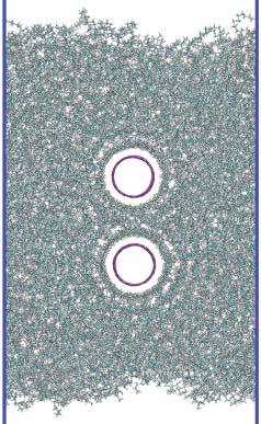

57 Figure 4.6 A snapshot of computational model for PE / CNT composite 46
58 CNT-CNT Interaction Through the Polymer During final structure relaxation process for 400 ps including the effect of longrange interactions, we quantify total force on CNTs with fixing the CNT-CNT distance. Forces are averaged from last 40 ps relaxation process and shown in Fig 4.7. Interference between alternative different polymer density layers cause repulsive and attractive force on the CNTs depending on the CNT distances. When each adsorption layers generated from different CNTs are overlapped in destructively CNTs are experiencing repulsive or attractive force to find the constructive overlapped position. Also the strength of forces on the CNTs is proportional to the density of layers. As the CNT adsorption layer formation vanishes around ~30 Å, shown in RDF analysis, interactions between the CNT also become weaker and force converges to the zero when CNTs are further away than ~30 Å. Effective interaction between CNTs via the polymer matrix leads the CNTs to find stable separation distances between the CNT in the PE matrix. During this procedure CNTs are free to move by being included in time integration on equation of motion. Figure 4.7 shows convergence of CNT distances to several equilibrium distances during relaxation at 400K. And predicted equilibrium distances between two CNTs are exactly correspond to the stable distances estimated from force analysis as shown in Figure 4.7 From the force and equilibrium distance analysis, we find that the short-range interaction is governed by the interactions between the perturbations the CNTs cause on the polymer density.
 Force on CNT as a function of distance between two CNTs, (b)")
59 Figure 4.7 (a) Force on CNT as a function of distance between two CNTs, (b) CNT CNT distances convergence as a function of time at 400K 48
60 Formation of Discrete Adsorption Layers The projected radial distribution functions along the CNT axis of polyethylene in the vicinity of CNT as function of distance from the center of CNTs are shown in Figure.4.8. RDF are averaged 5 sets of frame for each CNTs distance systems. The discrete peaks at ~10.5 A, ~15.3 A and ~19.8 A in RDF result shows that presence of CNTs leads the formation of polyethylene discrete dense adsorption layers. The largest peak of RDF is shown in first layer, gets dense up to g(r) of ~ 4.5, and diminishes with increasing distance from CNT for 2 nd and 3 rd peaks. We observe densification of adsorption layer in all systems with CNT distance range from 17 Å to 33 Å. These densifications of adsorption layers and degree of densification for each peak and effective range of molecular structure does not depend on the CNT alignment distances. These phenomena of molten polymer layers density oscillation and amplitude decaying with increasing distance from surface has been reported in experiment [44,46] and simulation [43,44,45] study. It is also suggested from recent study that polymer molecules heterogeneous density play significant role in relaxation behavior and also alter the dynamics [47,48].
61 50 Figure 4.8 Densification of adsorption layers at 400 K Considering the temperature for application of composite, we cooled down the systems from 400K to 50K for solid states composite using procedure of isochoric, isothermal conditions (NVT) with a rate of 25 K every 100 ps with CNTs on stable distance. As decrease the temperature, magnitudes of g (r) gets higher especially first peak up to ~8 times. In Figure 4.9 represent RDF at 50K with various center to center distances of CNT.
62 51 Figure 4.9 Densification of adsorption layers at 50 K 4.4 Many Body Effects in CNT CNT Interactions To investigate multiple interactions between CNTs through the polymer in comparison with pairwise interactions, we built 3-CNT embedded systems with different 3 rd CNT distance from rest of CNTs. Polymers in these systems are generated using PolymerModeler with 3 excluded cylinders for CNTs followed by relaxing with embedded CNT fixing distances between CNTs. Two CNTs are placed far away from each other Å in parallel alignment for all system and 3 rd CNT embedded on vertex point of isosceles triangle. 3 rd CNT distance from two other CNTs are Å, 20.3 Å, 22.4 Å, 24.5 Å and 26.6 Å as shown in Fig Third CNT distances are determined based on the pair wise interaction analysis, so that we can compare many body effects in CNT CNT interaction with pair-wise interaction.
 (c)")


63 52 (a) (b) (c) (d) (e) Figure 4.10 Atomistic snapshot of 3CNT embedded PE composites.
64 53 After minimization procedure using gradual application of van der Waals interactions, unscaled Dreiding exponential -6 van der Waals interactions are applied for dynamics at 400K using the same procedures for two CNTs embedded PE composites. Force on 3 rd CNTs are estimated based on the pair wise interaction analysis which is represented in Figrue 4.11 Also multiple CNT interaction quantified from last 40 ps relaxation process same as two CNT systems. Figure 4.11 Three body interactions effects in CNT-CNT composite

65 The estimated forces on 3 rd CNTs from two other CNTs are calculated as shown in Fig 4.12: 54 CNT3 CNT1 CNT2 Figure 4.12 Three-body Force analysis cartoon Interactions from three-body which is quantified from force on z-axis on equilibrated polymer structures are predicted stronger than estimated interactions from pair-wise system on both of regions, repulsive and attractive interaction zone. However the strengthened interaction of three-body system are diminishes as CNT distance increases. So as 3 rd CNTs is placed on further away position, interaction strength deviation between pair wise and three body system decreased. In hexagonal structure interaction strengthening is also observed.
 (c)")
")


66 55 (a) (b) (c) (d) (e) (f) Figure 4.13 Atomistic snapshot of hexagonal CNT structures embedded in PE composites
MECHANICS OF CARBON NANOTUBE BASED COMPOSITES WITH MOLECULAR DYNAMICS AND MORI TANAKA METHODS. Vinu Unnithan and J. N. Reddy
 MECHANICS OF CARBON NANOTUBE BASED COMPOSITES WITH MOLECULAR DYNAMICS AND MORI TANAKA METHODS Vinu Unnithan and J. N. Reddy US-South American Workshop: Mechanics and Advanced Materials Research and Education
Introduction to molecular dynamics
 1 Introduction to molecular dynamics Yves Lansac Université François Rabelais, Tours, France Visiting MSE, GIST for the summer Molecular Simulation 2 Molecular simulation is a computational experiment.
Shear Properties and Wrinkling Behaviors of Finite Sized Graphene
 Shear Properties and Wrinkling Behaviors of Finite Sized Graphene Kyoungmin Min, Namjung Kim and Ravi Bhadauria May 10, 2010 Abstract In this project, we investigate the shear properties of finite sized
A MOLECULAR DYNAMICS STUDY OF POLYMER/GRAPHENE NANOCOMPOSITES
 A MOLECULAR DYNAMICS STUDY OF POLYMER/GRAPHENE NANOCOMPOSITES Anastassia N. Rissanou b,c*, Vagelis Harmandaris a,b,c* a Department of Applied Mathematics, University of Crete, GR-79, Heraklion, Crete,
EFFECT OF VACANCY DEFECTS ON THE MECHANICAL PROPERTIES OF CARBON NANOTUBE REINFORCED POLYPROPYLENE
 International Journal of Mechanical Engineering and Technology (IJMET) Volume 8, Issue 7, July 2017, pp. 1370 1375, Article ID: IJMET_08_07_148 Available online at http://www.iaeme.com/ijmet/issues.asp?jtype=ijmet&vtype=8&itype=7
Supplementary Materials
 Supplementary Materials Atomistic Origin of Brittle Failure of Boron Carbide from Large Scale Reactive Dynamics Simulations; Suggestions toward Improved Ductility Qi An and William A. Goddard III * Materials
Glass-Transition and Side-Chain Dynamics in Thin Films: Explaining. Dissimilar Free Surface Effects for Polystyrene and Poly(methyl methacrylate)
") Supporting Information for Glass-Transition and Side-Chain Dynamics in Thin Films: Explaining Dissimilar Free Surface Effects for Polystyrene and Poly(methyl methacrylate) David D. Hsu, Wenjie Xia, Jake
Supporting Information for Glass-Transition and Side-Chain Dynamics in Thin Films: Explaining Dissimilar Free Surface Effects for Polystyrene and Poly(methyl methacrylate) David D. Hsu, Wenjie Xia, Jake
Mechanical Properties of Polymers. Scope. MSE 383, Unit 3-1. Joshua U. Otaigbe Iowa State University Materials Science & Engineering Dept.
 Mechanical Properties of Polymers Scope MSE 383, Unit 3-1 Joshua U. Otaigbe Iowa State University Materials Science & Engineering Dept. Structure - mechanical properties relations Time-dependent mechanical
Effect of different crosslink densities on the thermomechanical properties of polymer nanocomposites
 Effect of different crosslink densities on the thermomechanical properties of polymer nanocomposites *Byungjo Kim 1), Joonmyung Choi 2), Suyoung Yu 3), Seunghwa Yang 4) and Maenghyo Cho 5) 1), 2), 3),
Molecular Dynamics Simulations. Dr. Noelia Faginas Lago Dipartimento di Chimica,Biologia e Biotecnologie Università di Perugia
 Molecular Dynamics Simulations Dr. Noelia Faginas Lago Dipartimento di Chimica,Biologia e Biotecnologie Università di Perugia 1 An Introduction to Molecular Dynamics Simulations Macroscopic properties
Supplementary Figure 1. Schematic of rapid thermal annealing process: (a) indicates schematics and SEM cross-section of the initial layer-by-layer
 indicates schematics and SEM cross-section of the initial layer-by-layer") Supplementary Figure 1. Schematic of rapid thermal annealing process: (a) indicates schematics and SEM cross-section of the initial layer-by-layer film configuration, (b) demonstrates schematic and cross-section
Supplementary Figure 1. Schematic of rapid thermal annealing process: (a) indicates schematics and SEM cross-section of the initial layer-by-layer film configuration, (b) demonstrates schematic and cross-section
Electronic structure and transport in silicon nanostructures with non-ideal bonding environments
 Purdue University Purdue e-pubs Other Nanotechnology Publications Birck Nanotechnology Center 9-15-2008 Electronic structure and transport in silicon nanostructures with non-ideal bonding environments
MOLECULAR SIMULATION FOR PREDICTING MECHANICAL STRENGTH OF 3-D JUNCTIONED CARBON NANOSTRUCTURES
 ECCM16-16 TH EUROPEAN CONFERENCE ON COMPOSITE MATERIALS, Seville, Spain, 22-26 June 214 MOLECULAR SIMULATION FOR PREDICTING MECHANICAL STRENGTH OF 3-D JUNCTIONED CARBON NANOSTRUCTURES S. Sihn a,b*, V.
2. Amorphous or Crystalline Structurally, polymers in the solid state may be amorphous or crystalline. When polymers are cooled from the molten state
 2. Amorphous or Crystalline Structurally, polymers in the solid state may be amorphous or crystalline. When polymers are cooled from the molten state or concentrated from the solution, molecules are often
Mechanical properties of polymers: an overview. Suryasarathi Bose Dept. of Materials Engineering, IISc, Bangalore
 Mechanical properties of polymers: an overview Suryasarathi Bose Dept. of Materials Engineering, IISc, Bangalore UGC-NRCM Summer School on Mechanical Property Characterization- June 2012 Overview of polymer
Supporting Information Soft Nanoparticles: Nano Ionic Networks of Associated Ionic Polymers
 Electronic Supplementary Material (ESI) for Nanoscale. This journal is The Royal Society of Chemistry 2016 Supporting Information Soft Nanoparticles: Nano Ionic Networks of Associated Ionic Polymers Dipak
Johns Hopkins University What is Engineering? M. Karweit MATERIALS
 Why do things break? Why are some materials stronger than others? Why is steel tough? Why is glass brittle? What is toughness? strength? brittleness? Elemental material atoms: MATERIALS A. Composition
Molecular Dynamics Simulation of a Nanoconfined Water Film
 Molecular Dynamics Simulation of a Nanoconfined Water Film Kyle Lindquist, Shu-Han Chao May 7, 2013 1 Introduction The behavior of water confined in nano-scale environment is of interest in many applications.
Hyeyoung Shin a, Tod A. Pascal ab, William A. Goddard III abc*, and Hyungjun Kim a* Korea
 The Scaled Effective Solvent Method for Predicting the Equilibrium Ensemble of Structures with Analysis of Thermodynamic Properties of Amorphous Polyethylene Glycol-Water Mixtures Hyeyoung Shin a, Tod
A Molecular Dynamics Simulation of a Homogeneous Organic-Inorganic Hybrid Silica Membrane
 A Molecular Dynamics Simulation of a Homogeneous Organic-Inorganic Hybrid Silica Membrane Supplementary Information: Simulation Procedure and Physical Property Analysis Simulation Procedure The molecular
, to obtain a way to calculate stress from the energy function U(r).
.") BIOEN 36 014 LECTURE : MOLECULAR BASIS OF ELASTICITY Estimating Young s Modulus from Bond Energies and Structures First we consider solids, which include mostly nonbiological materials, such as metals,
BIOEN 36 014 LECTURE : MOLECULAR BASIS OF ELASTICITY Estimating Young s Modulus from Bond Energies and Structures First we consider solids, which include mostly nonbiological materials, such as metals,
MATERIALS. Why do things break? Why are some materials stronger than others? Why is steel tough? Why is glass brittle?
 MATERIALS Why do things break? Why are some materials stronger than others? Why is steel tough? Why is glass brittle? What is toughness? strength? brittleness? Elemental material atoms: A. Composition
Mechanical Properties of Tetra-Polyethylene and Tetra-Polyethylene Oxide Diamond Networks via Molecular Dynamics Simulations
 Supplemental Information Mechanical Properties of Tetra-Polyethylene and Tetra-Polyethylene Oxide Diamond Networks via Molecular Dynamics Simulations Endian Wang and Fernando A. Escobedo Table S1 Lennard-Jones
Diffusion of Water and Diatomic Oxygen in Poly(3-hexylthiophene) Melt: A Molecular Dynamics Simulation Study
 Melt: A Molecular Dynamics Simulation Study") Diffusion of Water and Diatomic Oxygen in Poly(3-hexylthiophene) Melt: A Molecular Dynamics Simulation Study Julia Deitz, Yeneneh Yimer, and Mesfin Tsige Department of Polymer Science University of Akron
Diffusion of Water and Diatomic Oxygen in Poly(3-hexylthiophene) Melt: A Molecular Dynamics Simulation Study Julia Deitz, Yeneneh Yimer, and Mesfin Tsige Department of Polymer Science University of Akron
The Molecular Dynamics Method
 The Molecular Dynamics Method Thermal motion of a lipid bilayer Water permeation through channels Selective sugar transport Potential Energy (hyper)surface What is Force? Energy U(x) F = d dx U(x) Conformation
How materials work. Compression Tension Bending Torsion
 Materials How materials work Compression Tension Bending Torsion Elemental material atoms: A. Composition a) Nucleus: protons (+), neutrons (0) b) Electrons (-) B. Neutral charge, i.e., # electrons = #
Supplementary Information for Atomistic Simulation of Spinodal Phase Separation Preceding Polymer Crystallization
 Supplementary Information for Atomistic Simulation of Spinodal Phase Separation Preceding Polymer Crystallization Richard H. Gee * Naida Lacevic and Laurence E. Fried University of California Lawrence
Universal Repulsive Contribution to the. Solvent-Induced Interaction Between Sizable, Curved Hydrophobes: Supporting Information
 Universal Repulsive Contribution to the Solvent-Induced Interaction Between Sizable, Curved Hydrophobes: Supporting Information B. Shadrack Jabes, Dusan Bratko, and Alenka Luzar Department of Chemistry,
Atomic Force Microscopy imaging and beyond
 Atomic Force Microscopy imaging and beyond Arif Mumtaz Magnetism and Magnetic Materials Group Department of Physics, QAU Coworkers: Prof. Dr. S.K.Hasanain M. Tariq Khan Alam Imaging and beyond Scanning
For an imposed stress history consisting of a rapidly applied step-function jump in
 Problem 2 (20 points) MASSACHUSETTS INSTITUTE OF TECHNOLOGY DEPARTMENT OF MECHANICAL ENGINEERING CAMBRIDGE, MASSACHUSETTS 0239 2.002 MECHANICS AND MATERIALS II SOLUTION for QUIZ NO. October 5, 2003 For
Nanotube AFM Probe Resolution
 Influence of Elastic Deformation on Single-Wall Carbon Nanotube AFM Probe Resolution Ian R. Shapiro, Santiago D. Solares, Maria J. Esplandiu, Lawrence A. Wade, William A. Goddard,* and C. Patrick Collier*
Fiber and Polymer Science Program, North Carolina State University. Materials Science and Engineering, North Carolina State University
 INTERFACIAL CHARACTERISTICS OF POLYMER NANOCOMPOSITES VIA MOLECULAR DYNAMICS SIMULATIONS Melissa A. Pasquinelli 1,2 *, Qian Jiang 3,4, and Joseph Moo-Young 2 1 Fiber and Polymer Science Program, North
Prediction of Young s Modulus of Graphene Sheets by the Finite Element Method
 American Journal of Mechanical Engineering, 15, Vol. 3, No. 6, 5-9 Available online at http://pubs.sciepub.com/ajme/3/6/14 Science and Education Publishing DOI:1.1691/ajme-3-6-14 Prediction of Young s
Advantages of a Finite Extensible Nonlinear Elastic Potential in Lattice Boltzmann Simulations
 The Hilltop Review Volume 7 Issue 1 Winter 2014 Article 10 December 2014 Advantages of a Finite Extensible Nonlinear Elastic Potential in Lattice Boltzmann Simulations Tai-Hsien Wu Western Michigan University
Fig. 1. Circular fiber and interphase between the fiber and the matrix.
 Finite element unit cell model based on ABAQUS for fiber reinforced composites Tian Tang Composites Manufacturing & Simulation Center, Purdue University West Lafayette, IN 47906 1. Problem Statement In
Chapter 7 Solid Surface
 Chapter 7 Solid Surface Definition of solid : A matter that is rigid and resists stress. Difference between solid and liquid surface : Liquid : always in equilibrium and equipotential. (Fig 7.1a,b) Solid
Comparison of COMPASS and PCFF in Calculating Mechanical Behaviors of Aramid Fiber by Means of Molecular Dynamics
 AMSE JOURNALS-AMSE IIETA publication-2017-series: Modelling B; Vol. 86; N 2; pp 438-446 Submitted Mar. 04; Revised May 12, 2017; Accepted Jun. 12, 2017 Comparison of COMPASS and PCFF in Calculating Mechanical
Polymer xxx (2012) 1e22. Contents lists available at SciVerse ScienceDirect. Polymer. journal homepage:
 1e22. Contents lists available at SciVerse ScienceDirect. Polymer. journal homepage:") Polymer xxx (2012) 1e22 Contents lists available at SciVerse ScienceDirect Polymer journal homepage: www.elsevier.com/locate/polymer Analysis of structural changes during plastic deformations of amorphous
Polymer xxx (2012) 1e22 Contents lists available at SciVerse ScienceDirect Polymer journal homepage: www.elsevier.com/locate/polymer Analysis of structural changes during plastic deformations of amorphous
T6.2 Molecular Mechanics
 T6.2 Molecular Mechanics We have seen that Benson group additivities are capable of giving heats of formation of molecules with accuracies comparable to those of the best ab initio procedures. However,
SUPPLEMENTARY INFORMATION
 SUPPLEMENTARY INFORMATION Supplementary Information Figure S1: (a) Initial configuration of hydroxyl and epoxy groups used in the MD calculations based on the observations of Cai et al. [Ref 27 in the
File ISM02. Dynamics of Soft Matter
 File ISM02 Dynamics of Soft Matter 1 Modes of dynamics Quantum Dynamics t: fs-ps, x: 0.1 nm (seldom of importance for soft matter) Molecular Dynamics t: ps µs, x: 1 10 nm Brownian Dynamics t: ns>ps, x:
NE 125 L. Title Page
 NE 125 L Title Page Name: Rajesh Swaminathan ID Number: 20194189 Partners Names: Clayton Szata 20193839 Sarvesh Varma 20203153 Experiment Number: 1 Experiment: Date Experiment was Started: Date Experiment
Why Proteins Fold? (Parts of this presentation are based on work of Ashok Kolaskar) CS490B: Introduction to Bioinformatics Mar.
 CS490B: Introduction to Bioinformatics Mar.") Why Proteins Fold? (Parts of this presentation are based on work of Ashok Kolaskar) CS490B: Introduction to Bioinformatics Mar. 25, 2002 Molecular Dynamics: Introduction At physiological conditions, the
Why Proteins Fold? (Parts of this presentation are based on work of Ashok Kolaskar) CS490B: Introduction to Bioinformatics Mar. 25, 2002 Molecular Dynamics: Introduction At physiological conditions, the
CHAPTER 4 MODELING OF MECHANICAL PROPERTIES OF POLYMER COMPOSITES
 CHAPTER 4 MODELING OF MECHANICAL PROPERTIES OF POLYMER COMPOSITES 4. Introduction Fillers added to polymer matrices as additives are generally intended for decreasing the cost (by increase in bulk) of
Computational Analysis for Composites
 Computational Analysis for Composites Professor Johann Sienz and Dr. Tony Murmu Swansea University July, 011 The topics covered include: OUTLINE Overview of composites and their applications Micromechanics
CITY UNIVERSITY OF HONG KONG. Theoretical Study of Electronic and Electrical Properties of Silicon Nanowires
 CITY UNIVERSITY OF HONG KONG Ë Theoretical Study of Electronic and Electrical Properties of Silicon Nanowires u Ä öä ªqk u{ Submitted to Department of Physics and Materials Science gkö y in Partial Fulfillment
VISCOELASTIC PROPERTIES OF POLYMERS
 VISCOELASTIC PROPERTIES OF POLYMERS John D. Ferry Professor of Chemistry University of Wisconsin THIRD EDITION JOHN WILEY & SONS New York Chichester Brisbane Toronto Singapore Contents 1. The Nature of
An Atomistic-based Cohesive Zone Model for Quasi-continua
 An Atomistic-based Cohesive Zone Model for Quasi-continua By Xiaowei Zeng and Shaofan Li Department of Civil and Environmental Engineering, University of California, Berkeley, CA94720, USA Extended Abstract
Why study protein dynamics?
 Why study protein dynamics? Protein flexibility is crucial for function. One average structure is not enough. Proteins constantly sample configurational space. Transport - binding and moving molecules
IAP 2006: From nano to macro: Introduction to atomistic modeling techniques and application in a case study of modeling fracture of copper (1.
 IAP 2006: From nano to macro: Introduction to atomistic modeling techniques and application in a case study of modeling fracture of copper (1.978 PDF) http://web.mit.edu/mbuehler/www/teaching/iap2006/intro.htm
SSNEMS Internal Report
 E.3. Nanotube Reinforced Piezoelectric Polymeric Composites Subjected to Electro-Thermo- Mechanical Loadings Understanding the stress transfer between nanotube reinforcements and surrounding matrix is
Deformation mechanisms of SiC reinforced nanocomposites under indentations
 Deformation mechanisms of SiC reinforced nanocomposites under indentations Mark Apicella, Youping Chen, and Liming Xiong Department of Mechanical and Aerospace Engineering, University of Florida, Gainesville,
Department of Engineering Mechanics, SVL, Xi an Jiaotong University, Xi an
 The statistical characteristics of static friction J. Wang, G. F. Wang*, and W. K. Yuan Department of Engineering Mechanics, SVL, Xi an Jiaotong University, Xi an 710049, China * E-mail: wanggf@mail.xjtu.edu.cn
CE 530 Molecular Simulation
 1 CE 530 Molecular Simulation Lecture 14 Molecular Models David A. Kofke Department of Chemical Engineering SUNY Buffalo kofke@eng.buffalo.edu 2 Review Monte Carlo ensemble averaging, no dynamics easy
(Refer Slide Time: 00:58)
") Nature and Properties of Materials Professor Bishak Bhattacharya Department of Mechanical Engineering Indian Institute of Technology Kanpur Lecture 18 Effect and Glass Transition Temperature In the last
Nature and Properties of Materials Professor Bishak Bhattacharya Department of Mechanical Engineering Indian Institute of Technology Kanpur Lecture 18 Effect and Glass Transition Temperature In the last
hydrated Nafion-117 for fuel cell application
 A molecular dynamics simulation study of oxygen within hydrated Nafion-117 for fuel cell application Jeffrey P. Fuller, Giuseppe F. Brunello, Seung Soon Jang School of Materials Science and Engineering
Class XI Physics Syllabus One Paper Three Hours Max Marks: 70
 Class XI Physics Syllabus 2013 One Paper Three Hours Max Marks: 70 Class XI Weightage Unit I Physical World & Measurement 03 Unit II Kinematics 10 Unit III Laws of Motion 10 Unit IV Work, Energy & Power
Enduring Understandings & Essential Knowledge for AP Chemistry
 Enduring Understandings & Essential Knowledge for AP Chemistry Big Idea 1: The chemical elements are fundamental building materials of matter, and all matter can be understood in terms of arrangements
Molecular Dynamics Simulations of Mechanical Properties of Boron-Nitride Nanotubes Embedded in Si-B-N Ceramics
 Molecular Dynamics Simulations of Mechanical Properties of Boron-Nitride Nanotubes Embedded in Si-B-N Ceramics Michael Griebel and Jan Hamaekers Department of Numerical Simulation, University of Bonn,
What is Classical Molecular Dynamics?
 What is Classical Molecular Dynamics? Simulation of explicit particles (atoms, ions,... ) Particles interact via relatively simple analytical potential functions Newton s equations of motion are integrated
Exercise: concepts from chapter 8
 Reading: Fundamentals of Structural Geology, Ch 8 1) The following exercises explore elementary concepts associated with a linear elastic material that is isotropic and homogeneous with respect to elastic
WATER PERMEATION THROUGH GRAPHENE NANOSLIT BY MOLECULAR DYNAMICS SIMULATION
 WATER PERMEATION THROUGH GRAPHENE NANOSLIT BY MOLECULAR DYNAMICS SIMULATION Taro Yamada 1 and Ryosuke Matsuzaki 2 1 Department of Mechanical Engineering, Tokyo University of Science, 2641 Yamazaki, Noda,
Supporting Information
 Projection of atomistic simulation data for the dynamics of entangled polymers onto the tube theory: Calculation of the segment survival probability function and comparison with modern tube models Pavlos
Study on mechanical model of Nafion membrane
 ICCM4 8-3 th July, Cambridge, England Abstract Study on mechanical model of Nafion membrane *I. Riku, K. Marui and K. Mimura Graduate School of Engineering, Osaka Prefecture niversity, -, Gakuen-cho, Naka-ku,
Part III : M6 Polymeric Materials
 16/1/004 Part III : M6 Polymeric Materials Course overview, motivations and objectives Isolated polymer chains Dr James Elliott 1.1 Course overview Two-part course building on Part IB and II First 6 lectures
Supplementary Figure 1 Experimental setup for crystal growth. Schematic drawing of the experimental setup for C 8 -BTBT crystal growth.
 Supplementary Figure 1 Experimental setup for crystal growth. Schematic drawing of the experimental setup for C 8 -BTBT crystal growth. Supplementary Figure 2 AFM study of the C 8 -BTBT crystal growth
Colloidal Suspension Rheology Chapter 1 Study Questions
 Colloidal Suspension Rheology Chapter 1 Study Questions 1. What forces act on a single colloidal particle suspended in a flowing fluid? Discuss the dependence of these forces on particle radius. 2. What
Nonlinear Mechanics of Monolayer Graphene Rui Huang
 Nonlinear Mechanics of Monolayer Graphene Rui Huang Center for Mechanics of Solids, Structures and Materials Department of Aerospace Engineering and Engineering Mechanics The University of Texas at Austin
Nanomechanics of carbon nanotubes and composites
 Nanomechanics of carbon nanotubes and composites Deepak Srivastava and Chenyu Wei Computational Nanotechnology, NASA Ames Research Center, Moffett Field, California 94035-1000; deepak@nas.nasa.gov Kyeongjae
Structural and Mechanical Properties of Nanostructures
 Master s in nanoscience Nanostructural properties Mechanical properties Structural and Mechanical Properties of Nanostructures Prof. Angel Rubio Dr. Letizia Chiodo Dpto. Fisica de Materiales, Facultad
Chap. 2. Polymers Introduction. - Polymers: synthetic materials <--> natural materials
 Chap. 2. Polymers 2.1. Introduction - Polymers: synthetic materials natural materials no gas phase, not simple liquid (much more viscous), not perfectly crystalline, etc 2.3. Polymer Chain Conformation
Physics of disordered materials. Gunnar A. Niklasson Solid State Physics Department of Engineering Sciences Uppsala University
 Physics of disordered materials Gunnar A. Niklasson Solid State Physics Department of Engineering Sciences Uppsala University Course plan Familiarity with the basic description of disordered structures
Instabilities in Thin Polymer Films: From Pattern Formation to Rupture
 Instabilities in Thin Polymer Films: From Pattern Formation to Rupture John R. Dutcher*, Kari Dalnoki-Veress Η, Bernie G. Nickel and Connie B. Roth Department of Physics, University of Guelph, Guelph,
St Olave s Grammar School. AS Physics Mock Revision Checklist
 St Olave s Grammar School Mock Practical skills.. a Can you design experiments, including ones to solve problems set in a practical context?.. b Can you identify the variables that must be controlled in
MECHANICAL PROPERTIES OF MATERIALS
 1 MECHANICAL PROPERTIES OF MATERIALS Pressure in Solids: Pressure in Liquids: Pressure = force area (P = F A ) 1 Pressure = height density gravity (P = hρg) 2 Deriving Pressure in a Liquid Recall that:
Example questions for Molecular modelling (Level 4) Dr. Adrian Mulholland
 Dr. Adrian Mulholland") Example questions for Molecular modelling (Level 4) Dr. Adrian Mulholland 1) Question. Two methods which are widely used for the optimization of molecular geometies are the Steepest descents and Newton-Raphson
Example questions for Molecular modelling (Level 4) Dr. Adrian Mulholland 1) Question. Two methods which are widely used for the optimization of molecular geometies are the Steepest descents and Newton-Raphson
MATERIALS SCIENCE POLYMERS
 POLYMERS 1) Types of Polymer (a) Plastic Possibly the largest number of different polymeric materials come under the plastic classification. Polyethylene, polypropylene, polyvinyl chloride, polystyrene,
DIVIDED SYLLABUS ( ) - CLASS XI PHYSICS (CODE 042) COURSE STRUCTURE APRIL
 - CLASS XI PHYSICS (CODE 042) COURSE STRUCTURE APRIL") DIVIDED SYLLABUS (2015-16 ) - CLASS XI PHYSICS (CODE 042) COURSE STRUCTURE APRIL Unit I: Physical World and Measurement Physics Need for measurement: Units of measurement; systems of units; SI units, fundamental
DIVIDED SYLLABUS (2015-16 ) - CLASS XI PHYSICS (CODE 042) COURSE STRUCTURE APRIL Unit I: Physical World and Measurement Physics Need for measurement: Units of measurement; systems of units; SI units, fundamental
Study of mechanical and thermal behavior of polymeric ablator using MD
 Study of mechanical and thermal behavior of polymeric ablator using MD Abhishek Kumar PhD Student Veera Sundararaghavan Assistant Professor of Aerospace Engineering University of Michigan, Ann Arbor Outline
Solutions for Assignment-8
 Solutions for Assignment-8 Q1. The process of adding impurities to a pure semiconductor is called: [1] (a) Mixing (b) Doping (c) Diffusing (d) None of the above In semiconductor production, doping intentionally
MOLECULAR MODELING OF THERMOSETTING POLYMERS: EFFECTS OF DEGREE OF CURING AND CHAIN LENGTH ON THERMO-MECHANICAL PROPERTIES
 18 TH INTERNATIONAL CONFERENCE ON COMPOSITE MATERIALS MOLECULAR MODELING OF THERMOSETTING POLYMERS: EFFECTS OF DEGREE OF CURING AND CHAIN LENGTH ON THERMO-MECHANICAL PROPERTIES N. B. Shenogina 1, M. Tsige
Micromechanics of Colloidal Suspensions: Dynamics of shear-induced aggregation
 : Dynamics of shear-induced aggregation G. Frungieri, J. Debona, M. Vanni Politecnico di Torino Dept. of Applied Science and Technology Lagrangian transport: from complex flows to complex fluids Lecce,
Carbon nanotubes in a nutshell. Graphite band structure. What is a carbon nanotube? Start by considering graphite.
 Carbon nanotubes in a nutshell What is a carbon nanotube? Start by considering graphite. sp 2 bonded carbon. Each atom connected to 3 neighbors w/ 120 degree bond angles. Hybridized π bonding across whole
The micro-properties of [hmpy+] [Tf 2 N-] Ionic liquid: a simulation. study. 1. Introduction
![The micro-properties of [hmpy+] [Tf 2 N-] Ionic liquid: a simulation. study. 1. Introduction](/thumbs/72/66941683.jpg "The micro-properties of [hmpy+] [Tf 2 N-] Ionic liquid: a simulation. study. 1. Introduction") ISBN 978-1-84626-081-0 Proceedings of the 2010 International Conference on Application of Mathematics and Physics Volume 1: Advances on Space Weather, Meteorology and Applied Physics Nanjing, P. R. China,
ISBN 978-1-84626-081-0 Proceedings of the 2010 International Conference on Application of Mathematics and Physics Volume 1: Advances on Space Weather, Meteorology and Applied Physics Nanjing, P. R. China,
XI. NANOMECHANICS OF GRAPHENE
 XI. NANOMECHANICS OF GRAPHENE Carbon is an element of extraordinary properties. The carbon-carbon bond possesses large magnitude cohesive strength through its covalent bonds. Elemental carbon appears in
MACROSCALE EXPERIMENTAL EVIDENCE OF A REDUCED- MOBILITY NON-BULK POLYMER PHASE IN NANOTUBE- REINFORCED POLYMERS
 MACROSCALE EXPERIMETAL EVIDECE OF A REDUCED- MOBILITY O-BULK POLYMER PHASE I AOTUBE- REIFORCED POLYMERS F.T. Fisher and L.C. Brinson Department of Mechanical Engineering orthwestern University Evanston,
Mechanical Interactions at the Interfaces of Atomically Thin Materials (Graphene)
") Mechanical Interactions at the Interfaces of Atomically Thin Materials (Graphene) Rui Huang Center for Mechanics of Solids, Structures and Materials Department of Aerospace Engineering and Engineering
Mechanical Interactions at the Interfaces of Atomically Thin Materials (Graphene) Rui Huang Center for Mechanics of Solids, Structures and Materials Department of Aerospace Engineering and Engineering
Molecular Mechanics. I. Quantum mechanical treatment of molecular systems
 Molecular Mechanics I. Quantum mechanical treatment of molecular systems The first principle approach for describing the properties of molecules, including proteins, involves quantum mechanics. For example,
 A Nobel Prize for Molecular Dynamics and QM/MM What is Classical Molecular Dynamics? Simulation of explicit particles (atoms, ions,... ) Particles interact via relatively simple analytical potential
EE 5344 Introduction to MEMS CHAPTER 6 Mechanical Sensors. 1. Position Displacement x, θ 2. Velocity, speed Kinematic
 I. Mechanical Measurands: 1. Classification of main types: EE 5344 Introduction MEMS CHAPTER 6 Mechanical Sensors 1. Position Displacement x, θ. Velocity, speed Kinematic dx dθ v =, = ω 3. Acceleration
Polymer Nanocomposites: Introduction
 Chapter 1 Polymer Nanocomposites: Introduction Downloaded via 148.251.232.83 on April 5, 2019 at 22:23:00 (UTC). See https://pubs.acs.org/sharingguidelines for options on how to legitimately share published
Chapter 7. Highlights:
 Chapter 7 Highlights: 1. Understand the basic concepts of engineering stress and strain, yield strength, tensile strength, Young's(elastic) modulus, ductility, toughness, resilience, true stress and true
An Energy Dissipative Constitutive Model for Multi-Surface Interfaces at Weld Defect Sites in Ultrasonic Consolidation
 An Energy Dissipative Constitutive Model for Multi-Surface Interfaces at Weld Defect Sites in Ultrasonic Consolidation Nachiket Patil, Deepankar Pal and Brent E. Stucker Industrial Engineering, University
Scientific Computing II
 Scientific Computing II Molecular Dynamics Simulation Michael Bader SCCS Summer Term 2015 Molecular Dynamics Simulation, Summer Term 2015 1 Continuum Mechanics for Fluid Mechanics? Molecular Dynamics the
VIBRATION CHARACTERISTICS OF EMBEDDED DOUBLE WALLED CARBON NANOTUBES SUBJECTED TO AN AXIAL PRESSURE
 18 TH INTERNATIONAL CONFERENCE ON COMPOSITE MATERIALS VIBRATION CHARACTERISTICS OF EMBEDDED DOUBLE WALLED CARBON NANOTUBES SUBJECTED TO AN AXIAL PRESSURE X. W. Lei 1, T. Natsuki 2, J. X. Shi 1, Q. Q. Ni
Crosslinking PMMA: Molecular Dynamics Investigation of the Shear Response
 FULL PAPER WWW.POLYMERPHYSICS.ORG JOURNAL OF POLYMER SCIENCE Crosslinking PMMA: Molecular Dynamics Investigation of the Shear Response Kyoungmin Min, 1,2 Meredith Silberstein, 2 N. R. Aluru 1,2 1 Department
6.5 mm. ε = 1%, r = 9.4 mm. ε = 3%, r = 3.1 mm
 Supplementary Information Supplementary Figures Gold wires Substrate Compression holder 6.5 mm Supplementary Figure 1 Picture of the compression holder. 6.5 mm ε = 0% ε = 1%, r = 9.4 mm ε = 2%, r = 4.7
MD Thermodynamics. Lecture 12 3/26/18. Harvard SEAS AP 275 Atomistic Modeling of Materials Boris Kozinsky
 MD Thermodynamics Lecture 1 3/6/18 1 Molecular dynamics The force depends on positions only (not velocities) Total energy is conserved (micro canonical evolution) Newton s equations of motion (second order
Molecular Aggregation
 Molecular Aggregation Structure Analysis and Molecular Simulation of Crystals and Liquids ANGELO GAVEZZOTTI University of Milano OXFORD UNIVERSITY PRESS Contents PART I FUNDAMENTALS 1 The molecule: structure,
Origins of Mechanical and Rheological Properties of Polymer Nanocomposites. Venkat Ganesan
 Department of Chemical Engineering University of Texas@Austin Origins of Mechanical and Rheological Properties of Polymer Nanocomposites Venkat Ganesan $$$: NSF DMR, Welch Foundation Megha Surve, Victor