STAF Linear Guide. STAF Linear Guide Integrated Rail for Non Cage Type and Cage Type.
|
|
|
- Oswin Whitehead
- 5 years ago
- Views:
Transcription


1 STAF Linear Guide STAF Linear Guide Integrated Rail for Non Cage Type and Cage Type
2
3 A. Terms of Linear Guide 1-1 Main Factors a. Lifetime and Load of Linear Guide Selection of linear guide has to be made on the static safety factor that is derived by comparing the calculated load of each slide according to its conditions and forces against the factors such as basic static load rating (C 0 ) or static permissible moment (M x, M y, M z ) to judge the reliability of the mechanism. For estimating the lifetime in long term, the basic dynamic load rating (C) has to be considered in calculating the distance durability. b. Basic Static Load Rating (C 0 ) When the linear guide receives excessive load, the grooves and the steel balls will be permanently deformed. The linear guide will no longer operate smoothly when the deformation exceeds limitation. The basic static load rating (C 0 ) is defined as the static load that will created the deformation of the grooves and steel ball to 1/10,000 of the steel ball diameter. c. Static Permissible Moment (M x, M y, M z ) When the linear guide receives a moment, the grooves and the steel balls will deform. A moment that causes deformation of the grooves and the steel balls to 1/10,000 of the steel ball diameter is called the static permissible moment. The static permissible moment in the X, Y and Z directions are M x, M y and M z individually. M z M x My A.Terms of Linear Guide 1
4 d. Static Safety Factor (fs) The static safety factor (f s ) is determined by the ratio of the load capacity (basic static load rating C 0 ) of the linear guide to the applied load on the linear guide. This factor reflects the reliability of the linear guide. Applied load is the force applied to the groove. To calculate the applied load, we have to calculate the load applied to the slide both vertical and parallel to the contact face of the groove. In the case of 4 symmetric loads at 45, the applied load is the sum of the parallel load and the vertical load. f s = f c P C 0 fs = f c M M 0 f s f c C 0 M 0 P M Static safety factor Contact factor Basic static load rating Static permissible moment Calculated load Calculated moment Static safety factor reference table: Operation condition Loading condition Min. f s Standing Operation Light impact and shift 1.0 ~ 1.3 Heavy impact and twist 2.0 ~ 3.0 Light impact and shift 1.0 ~ 1.5 Heavy impact and twist 2.5 ~ 5.0 e. Life Distance (L) Linear guide is a mass production product. Even though produced by the same processes and with the same materials, Life of individual linear guide is never the same. Life distance is the total travel distance that 90% linear guides would last before fatigue under certain operation conditions. f. Basic Dynamic Load Rating (C) If the life distance of certain linear guide is 50km, and if more than 90% of the linear guides would last for 50km under a of load of constant direction and magnitude that without peeling for fatigue, then the load is defined as the basic dynamic load rating. 2 A.Terms of Linear Guide
5 1-2 Subsidiary Factors a. Contact Factor (f c ) It is difficult to get even load distribution when linear guide blocks are closely arranged next to another due to moment load and accuracy of the mounting surface. Hence, in multiple linear guide application, basic static load rating (C) and basic dynamic load rating (C 0 ) have to be multiplied by contact factor (f c ) Number of Linear Guides Used Contact Factor (f c ) Normal use b. Hardness Factor (f h ) To maximize the load capacity of the linear guide, the hardness of the railways is best at between HRC 58 to 64. If the hardness is lower than HRC 58, the hardness factor (f h ) has to be brought into account for the basic dynamic load rating (C) and the basic static load rating (C 0 ). Hardness Factor (f h ) Railway Hardness (HRC) A.Terms of Linear Guide 3
6 c. Temperature Factor (f t ) When the ambient temperature exceeds 100, the adverse impact of high temperature must be considered, and the temperature factor must be brought into calculation. Hardness Factor (f h ) Railway Temperature ( C) Note) If the ambient temperature exceeds 80, high-temperature material must be used for the seals and the end plates. d. Load Factor (f w ) Reciprocal mechanisms tend to involve vibrations or impact in operation. Particularly, to determine appropriately the load generated by vibration in high-speed operation and the impact of frequent start-stop is very difficult. Hence, when the impact of vibration is significant, the basic dynamic load rating can be divided by the empirical load factors in the table below. Impact Speed (V) Vibration (G) f w Weak Low V <= 15 m/min G < = ~ 1.5 Medium Moderate 15 < V <= 60 m/min 0.5 < G < = ~ 2.0 Strong High V > 60 m/min 1.0 < G < = ~ A.Terms of Linear Guide
7 1-3 Life Calculation Formula Life distance of linear guides can be calculated from the basic dynamic load rating (C) and the applied load by the formula below: L = f h f t f c f w C P 3 50km L: Life distance (km) Life distance is the total travel distance that 90% of certain type linear guides would last before fatigue in operation under certain conditions individually. C: Basic dynamic load rating f h : Hardness factor f c : Contact factor P : Applied load f t : Temperature factor f w : Load factor When the life distance (L) is known, we can calculate the lifetime according to reciprocating stroke and frequency: L h = L 10 2 L s N L h = Lifetime (hr) N 1 = Reciprocation frequency (cycles/min) L s = Stroke (mm) A.Terms of Linear Guide 5
8 1-4 Friction Since the linear guide is the integration of the slide, the rail and the rolling elements such as balls or rollers, its movement is carried out by the rolling motion of the rolling elements, the friction can be as minor as 1/40 of the sliding guide. The static friction of linear guide is so small preventing the stick-slip so it is applicable to all sorts of accurate movements. The friction of a linear guide varies to the type of the linear guide, the preload, the viscosity of lubricant and the force applied. The friction increases especially when there is moment given or preload applied to increase rigidity. Friction characteristic of the STAF linear guide is shown as in the table below. Friction can be calculated with the formula below,. W+f F : Friction W: Load : Friction coefficient f : Friction of BG slide Friction of BG slide ( ) Load ration (P/C) P: Applied load C: Basic dynamic load rating Type Friction Type Friction BGX BGC BGX BGC BGX BGC BGX BGC BGX BGC BGX BGC BGX BGC A.Terms of Linear Guide
9 B. How to Select Linear Guide 2-1 Linear Guide Selection Step 2-2 Set the conditions 2-3 Select type and size 2-4 Confirm work load 2-5 Calculate equivalent load 2-6 Decide static safety factor 2-7 Check static safety factor NO YES 2-8 Calculate average load Calculate life distance NO 2-11 Check life time requirement YES 2-12 Select accessories Finalize conditions B.How to Select Linear Guide 7
10 2-2 Set the Condition Selection of linear guide has to be based on calculation. The informations required for such calculation are: A. assembly conditions (span, number of slides and number of rails); B. mounting position (horizontal, vertical, tilt or wall mount); C: applied load (magnitude, direction and position of force, and inertia under acceleration), D: frequency (load cycle). S 3 R3 X Y Z F(F x,f y,f z) S 4 R 4 P(P x,p y,p z) R2 O R1 S 2 L 0 L 1 S1 a. Assembly Conditions 1. Span: distance in between the slides such as L 0 and L 1 in the above figure. L 0 : distance in between the slides on one rail L 1 : distance in between the rails L 0 and L 1 are crucial to the rigidity and life of the linear motion system. 2. Number of slides: how many slides are mounted on the same rail. In the above figure, 2 slides are mounted on one rail. Normally, loading capacity and rigidity are increased as the number of slides increase, and so is the life. However, the operation space and the stroke must be brought into consideration. 3. Number of rails: how many rails are used in the system. In the above figure, 2 rails are used in the system. Normally, moment capacity is increased as the number of slides increase, and so are rigidity and life. 8 B.How to Select Linear Guide


11 b. Mounting Position 1. Horizontal mount mg mg Horizontal mount (load mg) This is the most common way of mounting with the load mg vertical to the slide plane and the sliding direction. It is most persistent to vertical load and is often used in normal positioning and feeding mechanism. 2. Vertical mount mg mg Vertical mount (load mg) In vertical mount, the load mg is parallel to the slides, so the slide span and its moment capacity are crucial. This is often seen in the elevator. Attention should be paid to the suspension of the load. The bigger the suspension is, the bigger the moment is. 3. Tilt mount mg mg Tilt mount (load mg) There are lateral tilted mount and longitudinal tilt mount. The load mg is vertical to the sliding direction in lateral tilt mount and is with an angle θ in longitudinal tilt mount. 4. Wall mount mg mg Wall mount (load mg) Moment is crucial for wall mount so the span in between slides affects the load on the slide and must be taken care of. The load mg is parallel to the slide plane and is vertical to the sliding direction. B.How to Select Linear Guide 9
12 c. Work Load The work load consist 3 elements - Magnitude, direction and position. 1. The workloads on the slide: Gravity: The mass of the slide forms the inertia during movement. External force: Force from the mechanism. This can be hydraulic, pneumatic or electro-magnetic. It will not form inertia during the movement. 2. Direction of work load: The external force can be divided into 3 components, F x, F y and F z as indicated in the right figure. F x is the external force in X-axis. F y is the external force in Y-axis. F z is the external force in Z-axis. L 1 Y S 4 R4 R3 S3 Z F(F x,f y,f z) P(P x,p y,p z) O R1 S1 R2 L 0 S2 X 3. Position of work load: As shown in the figure, take the slide centre for the origin point. The external force can be ball screw, hydraulic cylinder or linear motor. The relative position of the external force in X, Y and Z can then be defined. P fx : X position of external force in relation to centre. P fy : Y position of external force in relation to centre. P fz : Z position of external force in relation to centre. 4. Span: L 0 and L 1 stand for the distances in between the slides. 5. Velocity diagram: Velocity (V): Max operation velocity Travel distance (D): Total travel distance of the mechanism Acceleration distance (D 1 ): The distance travelled from start to max velocity Uniform distance (D 2 ): The distance travelled in constant velocity Deceleration distance (D 3 ): The distance travelled from max. velocity to stop V D 1 t 1 t 2 t(s) D 2 D 3 t 3 6. Work load on each slide: R 1, R 2, R 3 and R 4 are the vertical loads of each slide. S 1, S 2, S 3 and S 4 are the horizontal loads of each slide 10 B.How to Select Linear Guide
13 d. Work Frequency: When determining if the life time is satisfactory, the work frequency must be considered. E.g. 1, if the calculated life is 1,000km, and the daily travel is 1km, then the duration is 1,000 days. E.g. 2, if the calculated life is 50,000km, and the daily travel is 500km, then the duration is 100 days. 2-3 Select Type and Size a. Select the appropriate series (BGX or BGC) Select the appropriate series of linear guides. Please see our catalogues of BGX and BGC series for relevant information. b. Select an appropriate size among 15, 20, 25, 30, 35, 45 and 55 Select a size according to mechanical space without considering the load and the life. In the initial selection, it is difficult to judge load and life, and even if the safety factor is sufficient, it does not say that the life is sufficient. Hence, it is recommended to consider the size as the initial selection objective, and then select the bigger type when life or load is insufficient in practice. 2-4 Confirm Work Load The vertical forces on the slide are: -F z F z P x - F x P z R 1= L 0 F P - F y P 2 L 1 z y z -F z F z P x - F x P z R 2= L 0 F P - F y P 2 L 1 z y z -F z F z P x - F x P z R 3= L 0 F P - F y P 2 L 1 z y z -F z F z P x - F x P z R 4= L 0 F P - F y P 2 L 1 z y z R 3 S 3 X The horizontal forces on the slide are: Y Z F(Fx,Fy,Fz) F S 1 = S y 4 = + 4 F P - F x P 2 L 0 y x y S 4 R 4 P(Px,Py,Pz) R 2 F S 2 = S y 3 = 4 + F P - F x P 2 L 0 y x y O R1 S 2 L 0 L 1 S1 B.How to Select Linear Guide 11
14 Example: L 1 V R4 S 4 Y S1 R1 D 1 D 2 D 3 O P(P x,p y,p z) Z L 0 F(F x,0,0 ) R3 S3 t 1 t 2 t 3 S2 R2 t(s) X The movement can be divided into 3 sections: Acceleration section (Section A) Constant section (Section B) Deceleration section (Section C) Take linear guide BGXH20FN2 L4000 NZ0 for example: Known: C = 14.3kN, m = 98kg, P x = 0.08m, D 1 = 1m, D 2 = 2m, D 3 = 1m, F x = m(g+a), C 0 = 30.5kN, L 0 = 0.3m, P y = 0.25m, t 1 = 2s, t 2 = 2s, t 3 = 2s, F y = 0, V max = 1m/s L 1 = 0.5m P z = 0.28m a 1 = 0.5m/s a 2 = 0m/s a 3 = -0.5m/s F z = 0 V A B C t 1 t 2 t 3 t(s) 12 B.How to Select Linear Guide
15 Load calculation: -m(g+a R 2 (A) = R 3 (A) = 1 ). P z -98( ) = = 471.5N 2.L Section A F x (A) = m(g+a 1 ), F y (A) = 0, F z (A) = 0 -m(g+a R 1 (A) = R 4 (A) = 1 ). P z -98( ) = = N 2.L m(g+a R 2 (A) = R 3 (A) = 1 ). P z 98( ) = = 471.5N 2.L m(g+a S 1 (A) = S 4 (A) = 1 ). P y -98( ) = = N 2.L m(g+a S 2 (A) = S 3 (A) = 1 ). P y 98( ) = = 421.0N 2.L Section B F x (B) = m(g+a 2 ), F y (B) = 0, F z (B) = 0 -m(g+a R 1 (B) = R 4 (B) = 2 ). P z -98(9.81+0) = = N 2.L m(g+a R 2 (B) = R 3 (B) = 2 ). P z 98(9.81+0) = = 448.6N 2.L m(g+a S 1 (B) = S 4 (B) = 2 ). P y -98(9.81+0) = = N 2.L m(g+a S 2 (B) = S 3 (B) = 2 ). P y 98(9.81+0) = = 400.6N 2.L Section C F x (C) = m(g+a 1 ), F y (C) = 0, F z (C) = 0 -m(g+a R 1 (C) = R 4 (C) = 3 ). P z -98( ) = = N 2.L m(g+a R 2 (C) = R 3 (C) = 3 ). P z 98( ) = = 425.8N 2.L m(g+a S 1 (C) = S 4 (C) = 3 ). P y -98( ) = = N 2.L m(g+a S 2 (C) = S 3 (C) = 3 ). P y 98( ) = = 380.2N 2.L B.How to Select Linear Guide 13
16 2-5 Calculate Equivalent Load The vertical and horizontal load capacity depend on the contact angle between the slide and the rail. The equivalent load is different when the contact angle is 90 or 45. The contact angle in the STAF linear guides are designed 45 so as to get the same magnitudes of vertical and horizontal loads. The equivalent load on the rail (R e ) can be considers as the sum of vertical load magnitude (R n ) and the horizontal load magnitude (S n ). Vertical load : R n Horizontal load : S n The equivalent load is : R e = R n + S n Individual equivalent work load in section A: P (A)= R (A) + S (A) = =891.5 N P (A) = R (A) + S (A) = =891.5 N P (A) = R (A) + S (A) = =891.5 N P (A)= R (A) + S (A) = =891.5 N Individual equivalent work load in section B: P (B)= R (B) + S (B) = =849.2 N P (B) = R (B) + S (B) = =849.2 N P (B) = R (B) + S (B) = =849.2 N P (B) = R (B) + S (B) = =849.2 N Individual equivalent work load in section C: P (C)= R (C) + S (C) = =806 N P (C) = R (C) + S (C) = =806 N P (C) = R (C) + S (C) = =806 N P (C) = R (C) + S (C) = =806 N 14 B.How to Select Linear Guide
17 2-6 Decide Static Safety Factor Definition of static safety factor: Static safety factor calculation formula: f s = f c C 0 R e = (contact factor) (static load rating) max. individual equivalent load Static safety factor calculation formula: f s = f c M 0 M = (contact factor) (permissible moment) calculated moment Definition of static safety factor: It is difficult to get even load distribution when linear guide blocks are closely arranged next to another due to moment load and assembly accuracy. Hence, in multiple linear guide application, basic dynamic load rating (C) and basic static load rating (C 0 ) have to be multiplied by contact factor (f c ). Number of Linear Guides Used Normal use Contact Factor (f c ) Following the previous example: The max equivalent load (R e ) in the above example is 90.97kgf In the case of using linear guide BGXH20FN, The basic dynamic load, C = 1,43kN The basic static load, C 0 = 30.5kN Permissible moment in X-axis, Mx = kn m Permissible moment in Y-axis, My = kn m Permissible moment in Z-axis, Mz = kn m fc(normal use)= 1 f s = f c C 0 P = = (safety factor) B.How to Select Linear Guide 15
18 2-7 Check Static Safety Factor The table below are the reference values of static safety factor: Operation condition Loading condition Min. f s Standing-still Operation Light impact and shift 1.0 ~ 1.3 Heavy impact and twist 2.0 ~ 3.0 Light impact and shift 1.0 ~ 1.5 Heavy impact and twist 2.5 ~ Calculate Average Load Calculation of average load: There are several formulas of average load calculation according to work load variation pattern in movement. Stepwise load variation: P m : Average load (N) P n : Varying load (N) L : Total travel distance (m) L n : Corresponding travel distance of each varying load (m) Load (P) Total travel distance (L) (P 1 L 1 + P 2 L 2...P n Pm = [ L n ) ] L B.How to Select Linear Guide
19 Apply the formula in the example P m1 = = P m2 = = P m3 = = P m4 = = ( ( ( ( ( ( ( ( Monotonic load variation: P m = P 1 (A) 3. D1 +P 1 (B) 3. D2 +P 1 (C) 3. D3 D 1 +D 2 +D ( P min +2P max P min : min load (kgf) P max : max load (kgf) P 2 (A) 3. D1 +P 2 (B) 3. D2 +P 2 (C) 3. D3 D 1 +D 2 +D P 3 (A) 3. D1 +P 3 (B) 3. D2 +P 3 (C) 3. D3 D 1 +D 2 +D P 4 (A) 3. D1 +P 4 (B) 3. D2 +P 4 (C) 3. D3 D 1 +D 2 +D Monotonic load variation: ( ( ( ( ( ( 1 3 =850.0N ( 1 3 =850.0N ( 1 3 =850.0N ( 1 3 =850.0N Load (P) Load (P) Load (P) Total travel distance (L) Total travel distance (L) Total travel distance (L) B.How to Select Linear Guide 17
20 2-9 Calculate Life Distance Formula: L = f h f t f c f w C P 3 50km 2-8 Calculate Average Load L: life distance (km) C: basic dynamic load rating (kn) P: average load (kn) f c : contact factor f h : hardness factor f t : temperature factor f w : load factor e.g.: Basic dynamic load rating (C) of BGXH20FN is 14.3kN. Hardness factor (f h ) is 1 if hardness is HRC58. Temperature factor (f t ) is 1 under normal temperature. If contact factor (f c ) is 1, the velocity is 15<V<60m/s, load factor (f w ) is 1.5, and average load (P m ) is 850N. Then the life distance (L) is: L = f h f t f c f w C P km = km = km e.g.: Basic dynamic load rating (C) of BGXH25FN is 20.1kN. Hardness factor (f h ) is 0.8 if hardness is HRC55. Temperature factor (f t ) is 1 under normal temperature. Contact factor (f c ) is 0.81 for 2 slides close together, the velocity (V) is 60m/s, load factor (f w ) is 2, and average load (P m ) is 1530N. Then the life distance (L) is: L = f h f t f c f w C P km = km = km 18 B.How to Select Linear Guide
21 2-10 Calculate Life Time Formula (A) calculation of hours L h : life time by hours L: life distance (km) L s : stroke length (mm) L 10 6 L h = 2 Ls N 1 60 N 1 : reciprocations per minute (min-1) Formula (B) calculation of years L y : life time by years L: life distance (km) L s : stroke length (mm) N 1 : reciprocations per minute (min-1) M: work minutes per hour (min/hr) H: work hours per day (hr/day) D: work days per year (day/year) L y = L L s N 1 M H D E.g.1. A machine tool uses linear slides with the estimated life distance 45,000km. What is the life time by hour? Other conditions are as below, 1) Ls (the stroke length) is 3,000mm 2) N1 (the reciprocation) is 4 times per minute L L h = = = 31250hr 2 L s N E.g.2. A machine tool uses linear slides with the estimated life distance 71,231.5km. What is the life time by year? Other conditions are as below, 1) L s (the stroke length) is 4,000mm 2) N 1 (the reciprocation) is 5 times per minute 3) The machine operated 60 minutes an hour, 4) 24 hours a day, and 5) 360 days a year L 10 6 L y = = 2 L s N 1 M H D B.How to Select Linear Guide 19
22 2-11 Check Life Time Requirement If the calculated life time does meet the lifetime requirement, return and start from the beginning steps: 1) Set the conditions, or 2) Select type and size 1) Check the conditions over again: a. Assembly conditions (span, number of slides and number of rails): Is it necessary to increase the span? the number of slides? the number of rails? b. Mounting position (horizontal, vertical, tilt, wall hang or inverse): Is it necessary to modify the construction? c. Work load: Can the load be reduced? d. Work frequency: Is it the estimated frequency too big and lead to underestimation of life time? 2) Select type and size: If the conditions cannot be changed, then another type linear slide has to be selected. It is recommended to keep the size rails, and select a heavier type slide. Selecting a bigger rail will cause the drawbacks below, a. The weight of the mechanism will get bigger: The weight increases more when selecting a bigger rails than selecting a bigger slide. b. Design changes more: When a bigger rail is selected, 1. The screw hole span is bigger, 2. The screw size is bigger, 3. Contact with the base is bigger, 4. The securing mechanism has to be changed. When a bigger slide is selected, 1. The screw hole position has to be changed, 2. The length of the slide will depend on the interference, c. It will take bigger space: When a bigger rail is selected, there will be the changes below, 1. The total height is increased, 2. The total width is increased, 3. The screw size is bigger, When a bigger slide is selected, there will be very little change. d. Design cost will be increased: The variable cost of the rail is bigger than that of the slide. 20 B.How to Select Linear Guide

23 2-12 Type Coding System BGC H 25 BN 2 L 500 P Z1 I I Slide type: BGX: non-caged BGC: caged Assembly height: H: high assembly S: low assembly X: special assembly Size:mm Type and flange: BN: no flange/standard BS: no flange/short BL: no flange/long BE: no flange/extra long FN: flange/standard FS: flange/short FL: flange/long FE: flange/extra long Number of slides Dust protection category: : bottom & end seals UU: bottom seals ZZ: with scrapper DD: double seals KK: double seals+ scrapper SS: top+ bottom+ end seals E-(SD):top+ bottom+ double seals G-(GG):top+ bottom+ double seals+ scrapper Screw hole type: L: Counterbored C: Tapped hole Preload type: ZF: clearance Z0: Zero preload Z1: light preloaded Z2: medium preloaded Z3: heavy preloaded Accuracy Grade: N: normal H: high P: precision SP:super precision UP:ultra precision Rail length 2 rails in parallel B.How to Select Linear Guide 21
24 a. Accuracy Category Unit: mm Item Category Normal (N) High (H) Precision (P) Super Precision (SP) Ultra Precision (UP) Height tolerance (H) Width tolerance (W) Height difference ( H) ±0.1 ± ±0.04 ± Width difference ( W) Deviation of plane C vs. plane A Please refer to C in the diagram below for Deviation of plane D vs. plane B Please refer to D in the diagram below for Normal (N) High (H) Precision (P) Super Precision (SP) Ultra Precision (UP) Rail length (mm) BG accuracy vs. length 22 B.How to Select Linear Guide
25 b. Preload Selection What is preload? When rigidity of a linear guide is not strong enough, clearance will exist in between the elements. Preload is the load preliminarily applied to the rolling elements to eliminate a clearance of a linear guide and to increase its rigidity. Preload Clearance/Zero Preload Light Preload Medium & Heavy Preload Conditions 1. weak impact 2. 2 rails in pair 3. low accuracy 4. small resistance 5. small load 1. cantilever 2. single rail 3. light load 4. high accuracy 1. strong impact 2. strong vibration 3. heavy machining Applications 1. welding machine 2. chopping machine 3. feeding mechanism 4. tool change mechanism 5. ordinary XY table 6. packing machine 1. NC lathe 2. EDM 3. precise XY table 4. ordinary Z-axis 5. industrial robot 6. PCB punching machine 1. machine tool 2. NC lathe and milling machine 3. feeding axis of grinder 4. tool feeding axis Increase of preload will eliminate the vibration and the inertia impact in a reciprocating mechanism. However, increase of preload will increase the internal load and increase the assembly difficulty. Therefore, selection of linear guide must bring into account the preload and balance between the impact of vibration and of preload to life. B.How to Select Linear Guide 23
26 Preload C: dynamic load rating Category Clearance Free Zero preload Light preloaded Medium preloaded Heavy preloaded Code ZF Z0 Z1 Z2 Z3 Preload C 0.05C 0.07C *In case of even higher preload,please contact STAF/OME representative. Radial clearance Unit: m Type Preload ZF Z0 Z1 Z2 Z3 BG 15 4 ~ 8-3 ~ 3 4 ~ 8-13 ~ ~ -14 BG 20 4 ~ 8-3 ~ 3 4 ~ 8-14 ~ ~ -14 BG 25 5 ~ 10-4 ~ 4 5 ~ ~ ~ -18 BG 30 5 ~ 11-4 ~ 4 5 ~ ~ ~ -19 BG 35 6 ~ 12-5 ~ 5 6 ~ ~ ~ -20 BG 45 7 ~ 15-6 ~ 6 7 ~ ~ ~ -24 BG 55 8 ~ 19-7 ~ 7 8 ~ ~ ~ -30 Interchangeable or non-interchangeable Accuracy Category Non-interchangeable (by order) Interchangeable (stock) UP SP P H N H N ZF Z0 Z0 Z0 Z0 Z0 Preload Z1 Z1 Z1 Z1 Z1 Z1 Z1 Z2 Z2 Z2 Z2 Z2 Z3 Z3 Z3 24 B.How to Select Linear Guide
27 Recommended Mounting Surface Accuracy: Type BG 15 BG 20 BG 25 BG 30 BG 35 BG 45 BG 55 Allowance of Parallel Deviation (e1) Z3 Z2 Z1 Z0 ZF Unit: μm Allowance of Level Difference (e2) Z3 Z2 Z1 Z0 ZF B.How to Select Linear Guide 25

28 c. Rail Dust Protection Rail Contamination: Chips and foreign objects pile up easily in the screw holes that could damage the linear slides. Objects that gets into slide can block the internal circulation and shorten the life of the rails. Rail Cap: Most chips and foreign objects that fall on the rails can be wiped away by the seals. Only few will fall into the screw holes and get piled up. The purpose of the rail caps is to block the objects from falling into the screw holes. These caps can be easily mounted with a plastic mallet aligned with hole after the rail is secured. Tapped Hole Rails: The tapped hole rails are secured differently from the conventional rails. Since there is no through screw holes, dust and chips simply cannot pile up. Rail Type BG 15 BG 20 BG 25 BG 30 BG 35 BG 45 BG 55 Thread Size M5 M6 M6 M8 M8 M12 M14 Max Thread Length (L) 8mm 10 mm 12 mm 15 mm 17 mm 20mm 24 mm 26 B.How to Select Linear Guide


29 d. Accessories Scrapper: It is good for removing chips or splashes and is recommendable for cutting machines or flame cutters. It protects the end dust proof caps from the chips and splashes and maintains the functionin extreme ambient. Double end seal: 2 end seals mounted together: 1.The outer cap wipes away most unwanted particles. 2.The inner cap expels the particles not captured by the outer cap. Scrapper + double end seal: This combination gives both features of the above 2 constructions. Seal Type End Seal Bottom Seal Top Seal Double Seal Scrapper Not defined UU ZZ DD KK SS SD GG B.How to Select Linear Guide 27
30 C. How to Mount the Rails 3-1 Mounting Design Concept Ground surface Ground surface Type Biggest corner radiu of rail side (Ra) Clear height for rail (Hr) Clear Height for slide (Hs) Suggested thread length (Lb) BG M4x16 BG M5x20 BG M6x25 BG M8x30 BG M8x30 BG M12x35 BG M14x35 Linear Guide Assembly Steps Thrust screw Table Subsidiary side Datum plane Base Datum plane Master side Above figure shows a typical example for rail mounting with the features below, 1. There are 2 datum planes on the base. 2. There is a crosswise datum plane aligned by a thrust screw. 3. The table thrust screw is at the master side. 28 C.How to Mount the Rails


31 3-2 Mounting Steps Step 1: Clean up all the burrs, contamination objects and marks before mounting. Note: Datum plane is normally covered with antirust. Clean the antirust with detergent beforehand. It is recommended to spray some low viscosity lubricant to protect the datum plane. Step 2: Place the rail gently on the base and secure it with the thrust screw or other fixtures so that it contacts the datum plane nicely. Note: Check the alignment of the screw holes before securing. Forcing to secure the rail to unaligned screw holes will affect the accuracy and quality due over offset. C.How to Mount the Rails 29


32 Step 3: Attach the screws to screw holes in the sequence from centre to both ends. Push the rail gently against the datum plane. Fasten the screws in the sequence from centre to both ends slightly harder to make the rail more stable. Push the rail harder against the datum line to enhance the contact. Step 4: Secure the screws with a torque wrench with the appropriate torque selected according to based material. 30 C.How to Mount the Rails


33 Recommended rail screw fastening torque Screw size M 2 M 2.3 M 2.6 M 3 M 4 M 5 M 6 M 8 M 10 M 12 M 14 M 16 Fastening torque (kgf-cm) Steel Cast Iron Aluminum alloy Step 5: Mount the subsidiary rail with the same steps foresaid, and then mount the slides onto the rails individually. Pay attention to assemble all the accessories, such as grease fitting, oil fitting and seals in this stage otherwise it will be difficult to assemble the assemblies afterwards due to limited space. C.How to Mount the Rails 31


34 Step 6: Place the table gently on the slides on both master and subsidiary rails. Step 7: Fasten the crosswise thrust screw to secure the table. Fasten the table screws with the sequence demonstrated in the figure. 32 C.How to Mount the Rails


35 3-3 Common Mounting Styles C.How to Mount the Rails 33
36 3-4 Common Securing Styles 34 C.How to Mount the Rails
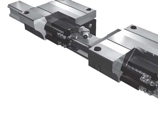
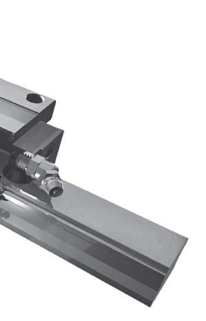
37 3-5 Use of Butt- Jointed Rail When a long rail is ordered, two or more rails can be butt- jointed to the desired length. When jointing rails, be sure to match the marked positions correctly as the above figure. When two or more linear guides with jointed rails are to be arranged parallel to each other, these linear guides will be numbered as the table below: Jointed rail #1 Jointed rail #2 Jointed rail #3 Jointed rail #N Parallel axis #01 No mark No mark Parallel axis #02 No mark No mark Parallel axis #26 No mark No mark C.How to Mount the Rails 35
38 3-6 Lubrication Volume Lubrication Grease Lubrication Oil Slide No Slide Type Initial lubrication (ml) Regular lubrication (ml) Initial lubrication (ml) Hourly lubrication(ml/ hr) N BN,FN BG-15 S L BS BL,FL BC-20 N S BN,FN BS L BL,FL N BN,FN BG-25 S L BS BL,FL E BE,FE N BN,FN BG-30 S L BS BL,FL E BE,FE N BN,FN BG-35 S L BS BL,FL E BE,FE BG-45 N L BN,FN BL,FL E BE,FE BG-55 N L BN,FN BL,FL E BE,FE Above figures are suggested volumes for initial and regular lubrication. It is recommended to re-lubricate every 100KM. Above figures are suggested volumes for initial and regular lubrication. It is recommended to re-lubricate every hour. Remark Notice When travel distance is less than twice slide length, it is suggested to put fittings at both ends. When travel distance is less slide length, it is suggested to move the slide back and forth over twice slide length in addition to putting fittings at both ends to ensure lubrication of the entire circulation loop. 36 C.How to Mount the Rails


39 Standard Linear Guide Caged Linear Guide 37

40 D. STAF Linear Guides Standard Type Standard type without flange Standard type with flange 38 D.STAF Linear Guides
41 4-1 BGX Conventional Linear Guides a. BGX 4-Groove Even Load Design The 4 rows of steel balls forms 45 contact with the grooves at 4 positions will balance the loads from all direction. This design that permits even load capacity in all directions no matter how the rails are mounted is widely adopted in all types of machines. Compared with the 2-groove Gothic design, the 4-groove construction is of better rigidity, accuracy and life. In particular, the auto-adjust capability allows quick accurate linear motions by eliminating the deviation of the mounting plane and the assembly errors. Comparison table of 4-groove vs. 2-groove 4-groove even load system 2-groove Gothic system The advantages are: 1. Quick light movements 2. Lower friction 3. Bigger load ratings 4. Higher stability D.STAF Linear Guides 39


42 b. BGX Seal Design Incursion of foreign objects is normally the major reason of life shortening for rails because the accuracy of linear guides relies very much on circulation of the steel ball between the slide and the rail. Even the incursion of smallest objects can cause skipping and bumping of the slide and lead to permanent damage. Therefore, seal design is the key to linear slide quality. The seal design in BGX linear guides is divided into top and bottom seal systems aiming at the incursion passage of the foreign objects. Passages of particle incursion: 1. Screw holes: The particles caught at the rail holes get into the circulation groove via vibration cause by machine movements. 2. Gap in between the slide and the rail: This is the closest incursion passage and is normally the passage for bigger particle particularly for the longer rails. Top seal system: Prevents the particle caught at the rail holes from entering the groove and improves the stability of the slide under extreme ambient. Bottom seal system: Prevents the particle from entering through the gap in between slide and rail for better protection of the circulation groove. Top seal system: Prevents the particle caught at the rail holes from entering the groove by covering it with a rubber wiper and protects the upper-row steel balls. Bottom seal system: The bottom seal system block the passage between slide and rail with the rubber wiper to secure smooth circulation of the steel balls. 40 D.STAF Linear Guides


43 c. BGX Tubular Muffling System High polymer tube eliminated the collision of steel balls when the slide moves in high speed The plastic bush eliminated the collision noise BGX rails Other designs Louder metallic collision noise The high polymer bush in BGX linear guide improves the lubrication. Advantages: 1. The slide moves quieter BGX linear guide use high polymer bush to isolate the circulating steel balls and eliminate the chances of unpleasant noises. 2. Better lubrication The high polymer bush in BGX linear guide improves the lubrication. 3. Uniform life time BGX circulation bush guarantees the expected life time of the linear slide for the facts below, 1. No noise of steel ball collision against the metallic tube as the conventional linear slides. 2. Lubrication is better compared to the conventional linear slides. 3. Less friction between the steel balls and the tube in high speed. D.STAF Linear Guides 41
44 d. BGX Oil Retaining in Circulation System BGX circulation system reserves a lot of space for retaining oil and is able to keeps a lot more oil. When linear slide moves, the oil inside spreads all over and prolongs the life of the construction due to the inertia. When the slide rests, the lubrication oil will return to the oil retainer in the circulation system without escaping. e. BGX Permissible Moment Loads calculation for linear guides differs between single-rail and dual-rail. In the single-rail system, calculating the load must consider the moment given by external force in 3 dimensions, and must calculate the equivalent load permissible moment. M z M x My 42 D.STAF Linear Guides

45 D. STAF Linear Guides Caged Type Caged type without flange Caged type with flange D.STAF Linear Guides 43
46 4-2 BGC Caged Liner Guides a. BGC for High Speed Application The steel balls rotate between the slide and the rail against each other in the conventional linear guides. Relative speed at the ball contact is 2 times the rotational speed. In addition, since the contact area is extremely small, the pressure is infinite (Please refer to the formula below). This is the major reason of steel ball wearing in conventional linear slides. In BGC linear slides, oil film is retained in between the balls to absorb friction and so is more ideal for high speed. P = F A P: Contact pressure between neighboring steel balls F: Interactive force between neighboring steel balls A: Contact area of neighboring steel balls Upper left figure: The steel balls rotate against each other in the conventional linear guides at the relative speed 2 times the rotational speed and the pressure is infinite because the contact area is extremely small. Upper right figure: In BGC linear guides, the retainer between the steel ball holds the oil and forms the oil film. Friction is absorbed by the oil film. The retainer allows the slide to move in high speed. In the BGC linear guides the steel balls are isolated by the oil film. Instead of contacting directly with relative speed twice as the rotational speed as in the conventional linear guides. Hence, the contact pressure of the conventional linear guides is a lot bigger than of the BGC linear guides. In conclusion, contact pressure and relative speed of BGC linear guides is far less than of the conventional ones and so the heat generated is less in the BGC linear guides. 44 D.STAF Linear Guides


47 b. BGC Lubrication by Retainer Circulation The lubrication oil injected from the fittings can be enhanced with the retainer circulation in the BGC linear guides. BGC linear guides surely have a longer life than the conventional, and even other caged type linear guides. As shown in the figures above, the oil film stays in the steel balls and the retainers. The unique retainer design in the BGC linear guides contains plenty of room to retain the oil. The retainer brings the oil to the circulation surface as it circulates. The retainer even keeps the oil better than the conventional linear guide in rest. In conventional linear guides, the steel balls contact directly with one another. Therefore, the lubrication flows away easily. Loss of lubrication oil will result in wearing, noise and heating. BGC linear guides provide an overall solution that can improve the performance and life. D.STAF Linear Guides 45
48 c. BGC Linear Guides Are Less Noisy The conventional linear guides are noisier because: 1. Relative speed at steel ball contact is twice of that in BGC linear guides. 2. The contact area is extremely small therefore the contact pressure is far larger than that in the BGC linear guides. Main causes of noises: In the conventional linear guides, the steel ball collides with one another and gives sharp noises. In the BGC linear guides, noises are mostly absorbed by the oil film created by the retainer, therefore the noise is far milder than the conventional ones. Noise is eliminated by the retainer and the silence tube. Metallic collision makes noise. When the steel balls travels in different speeds, the steel balls will catch up the steel ball ahead. In the conventional linear guides, collision happens and creates loud noises. The high polymer retainer in BGC linear guides separates the steel balls and carries oil film. Most of the collisions are absorbed by the elasticity of the retainer and the oil film and so the noises due to collision are suppressed. 46 D.STAF Linear Guides


49 d. More Evenly Distributed Load in BGC Linear Guides: The steel balls in conventional linear guides are not evenly arranged and the clearances between steel balls are not even. Hence the loads on individual steel balls are not even. As shown in the figure above, steel ball are randomly distributed in the conventional linear guides and unevenly loaded. As shown in the figure above, steel ball are randomly distributed in the conventional linear guides and unevenly loaded. This extra steel ball makes the performance more smooth. e. BGC Full Retainer Pack In most designs of linear guides with steel ball spacers, gaps of half to full size of steel balls are often found due to unfilled circulation loop. BGC linear guides provide a solution that fills this gap to arrange the steel balls tightly and distribute the load evenly which results in a uniform life. D.STAF Linear Guides 47
50 Low Noise Low Vibration 1/6 1/10 Vibration Amplitude in Caged Type Linear Guides Rolling Resistance (g) Type: BGXH25FN-Z1 Speed: 10mm/s Travel distance (mm) Noise (dba) Variation: 38% Rolling Resistance (g)) Type: BGCH25FN-Z1 Speed: 10mm/s Variation: 6% Travel distance (mm) Speed (m/min) f. BGC vs. Conventional Linear Guides High Speed Maintenance Noise Heating Load BGC Linear Guides Applicable Oil film easy to maintain Less Noisy Low Even Conventional Linear Guides Not Applicable Oil film not easy to maintain Noisy High Uneven 48 D.STAF Linear Guides
51 g. BGC Permissible Moment M z M x My Loads calculation for linear guides differs between single-rail and dual-rail. In the single-rail system, calculating the load must consider the moment given by external force in 3 dimensions, and must calculate the equivalent load permissible moment. D.STAF Linear Guides 49
52 BGX/BGC Specification Table (S-B) D.STAF Linear Guides
53 BGX/BGC Specification Table (H-F)(S-F) D.STAF Linear Guides 51
54 BGX/BGC Specification Table (H-B) D.STAF Linear Guides
55 E. STAF Parts & Accessories 5-1 Self-Lubricate Assembly a. Self-Lubricate Components Self-lubricate assembly automatically spreads the lubrication oil to form the oil film all over the rail rolling surface to lubricate the rolling elements appropriately. Different from conventional lubrication loop that delivers lubrication oil to the rolling elements, the combination of lubrication loop and self-lubricate assembly provides more reliable lubrication. Be sure to assemble the self-lubricate assembly cap outward to use the fitting correctly. Use lubrication oil of viscosity 100~400 to ensure the expected lubrication effect. If pressure lubrication is used simultaneously, reduce the pressure lubrication adequately. Slide End cap Self-lubricate assembly b. Specification of Self-Lubricate Assembly Self-lubricate assembly automatically spreads the lubrication oil to form the oil film all over the rail rolling surface to lubricate the rolling elements appropriately. Different from conventional lubrication loop that delivers lubrication oil to the rolling elements, the combination of lubrication loop and self-lubricate assembly provides more reliable lubrication. D: Thickness of single self-lubricate assemble V: Volume of oil lubrication Spec M x D(mm) V(cm 3 ) 15 type type type type type type type E.STAF Parts & Accessories 53
56 c. Self-Lubrication Performance It has been tested and proved in lab that there was residual oil after 500km of travel if recommended viscosity oil was applied. The self-lubricate assembly uses the same oil fitting as the end cap. There is no need to change the oil fitting. In use, the capillary foam in the assembly collects the excess oil. d. Assembly Compositions The self-lubricate assembly are composed of the following components: Oil retaining foam x 4 Enclosure cap x 1 Enclosure housing x 1 Bottom seal x 2 Contact felt x 2 e. Assembly Dimensions Series Type UU UU+SL assembly ZZ+SL assembly DD+SL assembly KK+SL assembly BGX 15 BGC BGX 20 BGC BGX 25 BGC BGX BGC 30 BGX BGC 35 BGX BGC 45 BGX 55 BGC S N L E S N L E S N L E S N L E S N L E N L E N L E E.STAF Parts & Accessories
 Thickness (mm) 15 type 10 0.")
57 5-2 Steel Band Assembly a. Steel Band Purpose The steel band covers the rail to prevent the slide from being damaged by the dust captured by the height difference between the hole cap and the rail. The steel band consists the components as in the figure below. Fixture Stopper Steel band M3 thrust screw Stopper b. Steel Band Specifications Spec Width (mm) Thickness (mm) 15 type (including adhesive) 20 type (including adhesive) 25 type 30 type (including adhesive) 0.3 (including adhesive) T 35 type (including adhesive) 45 type 55 type (including adhesive) 0.3 (including adhesive) W c. Steel Band Compositions 1. Steel band box: All steel band are packed in with the same box, but each type steel band varies in size and so are secured by paper stuff. 2. Steel band fixture: To secure the steel band accurately in the centre of the rail. 3. Stopper: To secure the steel bands extensions at both ends of the rail from falling off. d. Cautions Before attaching the steel band, clean up the rail surface thoroughly with detergent, and be sure there is no more oil left on the rail. 1. Be sure there is no more stains and contamination before attaching the steel band. 2. Use steel band only in temperature 20~40 C, or the effect is not guaranteed. 3. Keep hands off the adhesive to assure the best attaching result. 4. Shelf life of steel band is 6 month. E.STAF Parts & Accessories 55
58 e. Steel Band Attaching Steps Step 1. Step 5. Detaching Direction Push direction Steel band 1. detach the de-bonding paper tip Rail Step 2. Step 6. Stopper Fixture 2.Insert the debonded steel band into the fixture Steel band M3 thrust screw Stopper Push direction Rail Step 3. Steel Band Packing Contents Pilot port Fixture M3 thrust screw x 2 Stopper x 2 3.Insert the de-bonded steel band through the pilot port. Steel band packing: Step 4. Product packing Pull the steel band forward Steel band in carton box Packing 4.Turn the de-bonded steel band backward through the pilot port underneath the roller. 56 E.STAF Parts & Accessories
59 Appendix 1-1: Grease Fitting Specification Table G Grease Fitting L Elbow Fitting S 0 X 67.5 V UU ZZ DD KK SIDE 6 5 M4x0.7x3.5L UU ZZ DD KK SIDE UU ZZ DD KK SIDE NGS01 NGS02 NGS M4x0.7x5L 7 M4x0.7x8L UU ZZ DD KK SIDE UU ZZ DD KK SIDE NGS04 NGS05 NGS UU ZZ DD KK SIDE NGS UU ZZ DD KK SIDE NGS UU ZZ DD KK SIDE M6x1.0x5L M6x1.0x7L M6x1.0x12L M8x1.25x8L M8x1.25x12L UU ZZ DD KK SIDE UU ZZ DD KK SIDE NGX01 NGX02 NGX UU ZZ DD KK SIDE UU ZZ DD KK SIDE NGX04 NGX UU ZZ DD KK SIDE M6x1.0x5L M6x1.0x7L M6x1.0x12L M8x1.25x8L M8x1.25x12L E.STAF Parts & Accessories 57
60 Appendix 1-2: Grease Fitting Specification Table UU ZZ DD KK SIDE UU ZZ DD KK SIDE NGV01 NGV02 NGV UU ZZ DD KK SIDE M6x1.0x5L M6x1.0x7L UU ZZ DD KK SIDE UU ZZ DD KK SIDE NLS01 NLS02 NLS UU ZZ DD KK SIDE Ø7 Ø7 Ø7 M6x1.0x5L M6x1.0x12L M8x1.0 M8x1.0 M6x1.0x7L M8x UU ZZ DD KK SIDE UU ZZ DD KK SIDE NLV01 NLV02 NLV UU ZZ DD KK SIDE R3 R3 R M8x M8x1.0 M8x1.0 M6x1.0x5L M6x1.0x7L M6x1.0x12L UU ZZ DD KK SIDE NGV04 NGV05 UU ZZ DD KK SIDE M8x1.25x8L M8x1.25x12L UU ZZ DD KK SIDE NLS04 NLS05 UU ZZ DD KK SIDE Ø9 M8x1.0 M8x1.25x8L M8x1.0 M8x1.25x12L UU ZZ DD KK SIDE R Ø9 NLV04 NLV05 UU ZZ DD KK SIDE R3 M8x M6x1.0x12L M8x1.0 M8x1.25x8L M8x1.25x12L 58 E.STAF Parts & Accessories
61 MEMO 59
62 60 MEMO
The basic dynamic load rating C is a statistical number and it is based on 90% of the bearings surviving 50 km of travel carrying the full load.
 Technical data Load Rating & Life Under normal conditions, the linear rail system can be damaged by metal fatigue as the result of repeated stress. The repeated stress causes flaking of the raceways and
Identification Number
 Identification Number The specification of Micro Linear Way LWL is specified by the identification number, which consists of a model code, a size, a part code, a preload symbol, a classification symbol,
Precision Ball Screw/Spline
 58-2E Models BNS-A, BNS, NS-A and NS Seal Outer ring Shim plate Seal Spline nut Seal Collar Shim plate Seal End cap Ball Outer ring Ball screw nut Outer ring Ball Retainer Retainer Outer ring Point of
The SynchMotion. Retainer
 106 G99TE13-0809 Linear Guideways QE Series 2-9 QE Type Quiet Linear Guideway, with SynchMotion TM Technology The development of HIIN-QE linear guideway is based on a four-row circular-arc contact. The
 Identification The of -Lube Linear Roller Way Super MX is identified by the identification, which consists of model code, size, part code, material symbol preload symbol, classification symbol, interchangeable
Cam Roller Guides. The Drive and Control Company. Service Automation. Electric Drives and Controls. Linear Motion and Assembly Technologies
 Industrial Hydraulics Electric Drives and Controls Linear Motion and Assembly Technologies Pneumatics Service Automation Mobile Hydraulics Cam Roller Guides The Drive and Control Company Linear Motion
R-Plus System Frontespizio_R_PlusSystem.indd 1 11/06/ :32:02
 R-Plus System R-Plus System R-Plus system R-Plus system description Fig. R-Plus system R-Plus System is Rollon s series of rack & pinion driven actuators. Rollon R-Plus System series linear units are designed
Linear guide drives. Synchronous shafts The use of synchronous shafts enables several linear axes to be operated with one drive.
 Linear guide drives Drive concept The linear guides are driven via the hollow shaft in the drive head. The drive head is used to directly install a motor or alternatively (in connection with a center shaft)
C-Lube Linear Way ML Linear Way L ML LWL
 -Lube Linear ay ML Linear ay L MLLL -Lube Maintenance ree Series -Lube Linear ay ML ML long term maintenance free supported! The aquamarine end plate is the symbol of maintenance free. Identification umber
PROCESS FOR SELECTING NB LINEAR SYSTEM
 The NB linear system is a linear motion mechanism which utilizes the recirculating movement of ball or roller elements to provide smooth and accurate linear travel. NB offers a wide range of linear motion
Calculating the Applied Load
 The LM Guide is capable of receiving loads and moments in all directions that are generated due to the mounting orientation, alignment, gravity center position of a traveling object, thrust position and
Miniature Slide Guide Series with Retained Ball now Offers Complete Selection
 Miniature Slide Guide Series with Retained Ball now Offers Complete Selection Wide type of Miniature Slide Guide, providing greater allowable moment, is now available with retained ball structure. Due
Automatic Level Maintenance Manual SAL-XX W/ AIR DAMPENED COMPENSATOR
 Automatic Level Maintenance Manual SAL-XX W/ AIR DAMPENED COMPENSATOR CST/Berger 2001 SAL 20/24/28/32 PAGE 1 REV. C 071803 Automatic Level Maintenance Manual User Calibration and Testing... 3 Circular
SLIDE GUIDE SGL TYPE SLIDE GUIDE BLOCK TYPES ACCURACY
 SGL YPE he N slide is a linear motion earing utilizing the rotational motion of all elements along four rows of raceway grooves. It can e used in various applications due to its compactness and high load
Miniature (SEB Type) Tapped-Hole rail Types: Slide guides with clearance holes are standard and tapped holes are available upon request.
 Tapped-Hole rail Types: Slide guides with clearance holes are standard and tapped holes are available upon request.") Miniature (SE Type) The SE type slide guide is a linear motion bearing in which the ball elements roll along two tracking grooves. This is the smallest and lightest slide guide series offered by Nippon
Miniature (SE Type) The SE type slide guide is a linear motion bearing in which the ball elements roll along two tracking grooves. This is the smallest and lightest slide guide series offered by Nippon
General Explanation Ⅲ 1 Ⅲ 2
 General Explanation 1 2 Selection Procedure Selection of Linear Way and Linear Roller Way should be considered from the most important required matter to details in order. Typical procedure is shown below.
( ) Calculating the Nominal Life. Nominal Life Equation for an LM Guide Using Balls. Nominal Life Equation for the Oil-Free LM Guide L = ( C L =
 Calculating the Nominal Life. Nominal Life Equation for an LM Guide Using Balls. Nominal Life Equation for the Oil-Free LM Guide L = ( C L =") Point of Selection The service life of an LM Guide is subject to variations even under the same operational conditions. Therefore, it is necessary to use the nominal life defi ned below as a reference
Point of Selection The service life of an LM Guide is subject to variations even under the same operational conditions. Therefore, it is necessary to use the nominal life defi ned below as a reference
SLIDE GUIDE SGL TYPE SLIDE GUIDE BLOCK TYPES ACCURACY
 SGL YPE he N slide is a linear motion earing utilizing the rotational motion of all elements along four rows of raceway grooves. It can e used in various applications due to its compactness and high load
ADVANCED MOTION TECHNOLOGIES CORP.
 LINEAR GUIDEWAY ADVANCED MOTION TECHNOLOGIES COR. No.7, Lane 89, Chung Shan Rd., Shen Kang Hsiang, Taichung Hsien 49, Taiwan TEL: +886464 FAX: +8864686 Email: amt.info@pmiamt.com.tw Web site: www.pmiamt.com
CTV series CHARACTERISTICS LINEAR UNITS
 CTV series CHARACTERISTICS The CTV series describes s with a precision ball screw drive and two parallel, integrated, Zerobacklash rail guides. Compact dimensions allow high performance features such as,
Product Description. Further highlights. Outstanding features. 4 Bosch Rexroth Corporation Miniature Linear Modules R310A 2418 (2009.
 4 Bosch Rexroth orporation Miniature Linear Modules R310A 2418 (2009.05) Product Description Outstanding features Rexroth Miniature Linear Modules are precise, ready-to-install linear motion systems that
Load Washers. Force. for Forces of 7, kn. F z. Type 9001A A 9081B, 9091B
 Force Load Washers for Forces of 7,5... 1 200 kn Type 9001A... 9071A 9081B, 9091B 1-component force sensor for measuring dynamic and quasistatic forces in z direction. F z Calibrated measuring range 100
Identification system for short product names. Changes/amendments at a glance. 2 Bosch Rexroth AG OBB omega modules R ( )
") Omega Modules OBB 2 OBB omega modules R9990079 (206-05) Identification system for short product names Short product name Example: O B B - 085 - N N - System = Omega module Guideway = Ball Rail System Drive
Omega Modules OBB 2 OBB omega modules R9990079 (206-05) Identification system for short product names Short product name Example: O B B - 085 - N N - System = Omega module Guideway = Ball Rail System Drive
BEARINGS Pillow Blocks
 The bearing size is usually selected according to the required bearing life and reliability under a specified type of load charged on the bearing. The load applied to the bearing operating under a static
 Identification The specification of C-Lube Linear ay is identified by the identification, which consists of a model code, a size, a part code, a material code, a preload symbol, a classification symbol,
Vane Type Rotary Actuators Series Variations
 Vane Type Rotary Actuators Series Variations Vane Type Exterior CRB Series 0,, 0,, CRBU Series 0,, 0,, CRB Series, 6, 80, Has a compact body with exterior dimensions that do not change regardless of the
SNL plummer block housings, 2, 3, 5 and 6 series Other bearing housings Large SNL plummer block housings
 Bearing housings SNL plummer block housings, 2, 3, 5 and 6 series... 1033 Other bearing housings... 1058 Large SNL plummer block housings... 1058 SONL plummer block housings... 1059 SDG plummer block housings...
Maintenance Free C-Sleeve Linear Way ML ME MH MUL
 Maintenance ree C-Sleeve Linear ay M M MUL CAT-A e aim to be a Technology-Developing company taking customer-need as primary source for the development. ith our original technologies and creativities,
ER2 Short-head Electric Chain Hoist
 O/M NO.SHER2-0903-CE-00 ER2 Short-head Electric Chain Hoist (250kg to 5t) Operation Manual (SHER2M/SHER2SG/SHER2SP) Introduction The KITO Short-head Electric Chain Hoist is intended for effective use in
TE 75R RESEARCH RUBBER FRICTION TEST MACHINE
 TE 75R RESEARCH RUBBER FRICTION TEST MACHINE Background: The Research Rubber Friction Test Machine offers the ability to investigate fully the frictional behaviour of rubbery materials both in dry and
Formulae and examples of calculation
 Shock absorber Formulae and examples of calculation A shock absorber decelerates linearly. Roughly 90% of shock absorber applications can be modelled if the following 4 factors are known: 1. Mass to slow
C-Lube Linear Way ML ML MLF
 Maintenance ree & U.S. PTTD C-Lube Linear ay Variation of C-Lube Linear ay Shape Length of slide unit Model code C-Lube Linear ay is a linear motion rolling guide, incorporating the C-Lube as a components
Points. Precision Positioning Table TU. Variation. Major product specifications With flange
 9 0 Precision Positioning Table Ball screw inear Points lide table with high accuracy and high rigidity in a single structure lide table Compact and slim type positioning table with an original U-shaped
Example of Calculating the Nominal Life
 Condition (Horizontal Installation) Assumed model number : KR 5520A LM Guide unit (C = 800N, C 0 = 6900N) Ball Screw unit (C a = 620N, C 0a = 9290N) Bearing unit(fixed Side) (C a = 7600N, P 0a = 990N)
Product description. Compact Modules. Characteristic features. Further highlights
 4 Compact Modules Product description Characteristic features Five fine-tuned sizes based on a compact precision aluminum profile with two integrated pre-tensioned ball rail systems Identical external
FOUR-POINT CONTACT SLEWING RINGS - without gear [ O ]
![FOUR-POINT CONTACT SLEWING RINGS - without gear [ O ]](/thumbs/96/126795264.jpg "FOUR-POINT CONTACT SLEWING RINGS - without gear [ O ]") FOUR-POINT CONTACT SLEWING RINGS - without gear [ O ] Number of the Loading Boundary Dimensions Static Ax.Basic Load Rating Designation Weight Abutment Dimensions Curve d D T C oa G J 1 J 2 N 1 N 2 n 1
FOUR-POINT CONTACT SLEWING RINGS - without gear [ O ] Number of the Loading Boundary Dimensions Static Ax.Basic Load Rating Designation Weight Abutment Dimensions Curve d D T C oa G J 1 J 2 N 1 N 2 n 1
Drive Units with Ball Screw Drives R310EN 3304 ( ) The Drive & Control Company
 The Drive & Control Company") Drive Units with Ball Screw Drives R310EN 3304 (2007.05) The Drive & Control Company Linear Motion and Assembly Technologies Ball Rail Systems Roller Rail Systems Linear Bushings and Shafts Precision Ball
Drive Units with Ball Screw Drives R310EN 3304 (2007.05) The Drive & Control Company Linear Motion and Assembly Technologies Ball Rail Systems Roller Rail Systems Linear Bushings and Shafts Precision Ball
Ball screw. Linear. Coupling cover. 1Positioning table of a structure with enhanced sealing property. 3 High corrosion resistance
 Cleanroom Precision Positioning Table TC Ball screw TC EB Slide table inear Way Side cover Stainless sheet Motor bracket inear Coupling cover Pipe threads for suction connector Points ight weight, low
ZF Maschinenantriebe GmbH Industrial Drives. Planetary gearboxes Economy Series for Servomotors
 ZF Maschinenantriebe GmbH Industrial rives Planetary gearboxes Economy Series for Servomotors 2 ZF-uoplan 2K Two-speed Gearboxes ZF-Ecolift Elevator Gearboxes ZF-Servoplan G ompact Gearbox ZF-Tiratron
Series MHY2/MHW Angular Gripper. Cam actuation style is now standardized! MHZ2 MHZJ2 MHQ MHL2 MHR MHK MHS MHC2 MHT2 MHY2 MHW2 MRHQ 2.
 18 Angular Gripper Cam Style Rack & Pinion Style Series / Cam actuation style is now standardized! 2.8-1 18 Angular Gripper 18 Angular Gripper Series / Cam Style Rack & Pinion Style Series / Series MHY/Cam
PLOW MOUNT KIT FOR POLARIS RANGER P/N ASSEMBLY / OWNERS MANUAL
 PLOW MOUNT KIT FOR POLARIS RANGER P/N 34-3010 ASSEMBLY / OWNERS MANUAL Application PLOW PUSH FRAME NO. 34-0000 or 34-0070 Before you begin, please read these instructions and check to be sure all parts
Rodless cylinders Series 1600
 Rodless cylinders Series 00 Basic version 0.Ø.stroke.0.M Max. stroke mt.) AL AI RA RB AF TC AM L LA+stroke AH TD AE TA RV Possibility of a single feed cylinder head AI AP AB AC AD TD TE TB AG RT Left head
Chapter 11. Bearing Types. Bearing Load. The Reliability Goal. Selection of Tapered Roller Bearings
 Chapter 11 Rolling Contact Bearing Bearing Types Bearing Life Bearing Load Bearing Survival The Reliability Goal Selection of Ball and Straight Roller Bearings Selection of Tapered Roller Bearings 1 Introduction
SKF actuators available for quick delivery. Selection guide
 SKF actuators available for quick delivery Selection guide A wide range of SKF actuators available for quick delivery Industrial actuator 24 Volt DC Load range 1 000 to 4 000 N Speed range 5 to 52 mm/s
Selection Calculations For Linear & Rotary Actuators
 H-8 For Electric Linear Slides and Electric Cylinders First determine your series, then select your product. Select the actuator that you will use based on the following flow charts: Selection Procedure
AF SERIES AWEA MECHANTRONIC CO., LTD. High Performance Vertical Machining Center AGENT ISO 9001 ISO 14001
 AWEA MECHANTRONIC CO., LTD. HEADQUARTERS 629, Suezhetou Section, Kwanpu Rd., Wenshan Li, Hsinpu, Hsinchu, Taiwan TEL : +886-3-88-191 FAX : +886-3-88-19 Website : www.awea.com CENTRAL TAIWAN SCIENCE PARK
Notes on Rubber Friction
 Notes on Rubber Friction 2011 A G Plint Laws of Friction: In dry sliding between a given pair of materials under steady conditions, the coefficient of friction may be almost constant. This is the basis
Selection table for guided systems (crank driven)
") Selection table for guided systems (crank driven) One mass shaker brute-force system One mass shaker natural frequency system Two mass shaker fast-runner system with reaction force-compensation Single
Selection table for guided systems (crank driven) One mass shaker brute-force system One mass shaker natural frequency system Two mass shaker fast-runner system with reaction force-compensation Single
Maintenance Free C-Sleeve Linear Way
 U.S. PATTD Maintenance ree C-Sleeve Linear ay M M MUL Maintenance free for,000 km or or years CAT- Printed in Japan 0.0 (SIG Maintenance ree & C-Sleeve Linear ay strives to be a leader in Technology. Our
T20WN. Data Sheet. Torque transducers. Special features. Installation example with bellows couplings. B en
 T20WN Torque transducers Data Sheet Special features - Nominal (rated) torques 0.1 N m, 0.2 N m, 0. N m, 1 N m, 2 N m, N m, 10 N m, 20 N m, 0 N m, 100 N m, 200 N m - Accuracy class: 0.2 - Contactless transmission
OSCILLATIONS OF A SPRING-MASS SYSTEM AND A TORSIONAL PENDULUM
 EXPERIMENT Spring-Mass System and a Torsional Pendulum OSCILLATIONS OF A SPRING-MASS SYSTEM AND A TORSIONAL PENDULUM Structure.1 Introduction Objectives. Determination of Spring Constant Static Method
VX25 Enclosure System. Technical documentation PE conductor connection, current carrying capacity
 VX Enclosure System Technical documentation PE conductor connection, current carrying capacity Enclosure system VX Contents Contents. General remarks. Introduction. Notes on the design of the earthing
Bearing Internal Clearance and Preload
 . Bearing Internal Clearance and Preload. Bearing internal clearance Bearing internal clearance is the amount of internal free movement before mounting. As shown in Fig.., when either the inner ring or
Must Read Before Installation TadPoleTM Safety and Warnings
 Must Read Before Installation TadPoleTM Safety and Warnings The recommendations, requirements, rules, and instructions of your Vehicle's Roof-Top Rack System should ALWAYS be followed. The TadPole TM,
Ball Reverser. Ball Reverser Actuator. FLENNOR Power Transmission Products. Patented
 Ball Reverser FLENNOR Power Transmission Products Ball Reverser Actuator Patented Ball Reverser Principle General Information NORCO'S Ball Reverser Actuator is a unique actuator which provides automatic
ISO INTERNATIONAL STANDARD. Rolling bearings Thermal speed rating Calculation and coefficients
 INTERNATIONAL STANDARD ISO 1512 First edition 200-12-01 Rolling bearings Thermal speed rating Calculation and coefficients Roulements Vitesse de référence thermique Calculs et facteurs de correction Reference
HRN/HRN-C Series Hydraulic Vane Rotary Actuators
 HRN/ Hydraulic Vane Rotary Actuators Vane Actuators Tork-Mor HRN Contents Features... 2 Ordering Information... Engineering Data / Specifications... Dimensions... Features... 1 Ordering Information...12
ENGINEERING INFORMATION TABLE OF CONTENTS SHAFT AND HOUSING FITS LUBRICATION LIFE AND LOAD RATINGS RADIAL CLEARANCE CHART
 ENGINEERING INFORMATION TABLE OF CONTENTS ENGINEERING INFORMATION SHAFT AND HOUSING FITS LUBRICATION LIFE AND LOAD RATINGS RADIAL CLEARANCE CHART SHAFT AND HOUSING FITS FOR METRIC RADIAL BALL AND ROLLER
S.C. Rulmenti S.A. Barlad Romania Republicii Street No
 SELECTION OF BEARING SIZE Basic load ratings The size of a bearing is selected considering the load in the used rolling bearing and also depends on the operational rating life and prescribed operating
DRIFTER PLOW-IN-A-BOX ASSEMBLY / OWNER S MANUAL
 DRIFTER PLOW-IN-A-BOX ASSEMBLY / OWNER S MANUAL Part No: 10-0550 OPERATING INSTRUCTIONS Congratulations! You ve just purchased one of the industry s top plow systems. The DRIFTER Plow System works great
Simulation of process of hot pilgrim rolling
 Simulation of process of hot pilgrim rolling YURY B. CHECHULIN, Doctor of Engineering Science, Professor EVGENY U. RASKATOV, Doctor of Engineering Science, Professor YURY A. POPOV, post-graduate student
The SKF model for calculating the frictional moment
 The SKF model for calculating the frictional moment The SKF model for calculating the frictional moment Bearing friction is not constant and depends on certain tribological phenomena that occur in the
second PLSA line R310EN 3308 ( )
") 01_1 Planetary st Headline_36 Screw Assemblies pt/14.4 mm second PLSA line R310EN 3308 (2011-09) 2 Planetary Screw Assemblies PLSA Planetary Screw Assemblies PLSA Product Overview 3 Nuts, Screws, Screw
01_1 Planetary st Headline_36 Screw Assemblies pt/14.4 mm second PLSA line R310EN 3308 (2011-09) 2 Planetary Screw Assemblies PLSA Planetary Screw Assemblies PLSA Product Overview 3 Nuts, Screws, Screw
FOR CAN-AM ATV s P/N ASSEMBLY / OWNERS MANUAL
 MID-MOUNT KIT FOR CAN-AM ATV s P/N 15-7580 ASSEMBLY / OWNERS MANUAL Application PLOW PUSH FRAME NO. 15-0070, 33-0000 or 33-0070 Before you begin, please read these instructions and check to be sure all
Ballistic pendulum Operating Instructions Fig. 1: Ballistic pendulum SAFETY PRECAUTIONS
 R Ballistic pendulum 11229.00 PHYWE Systeme GmbH & Co. KG Robert-Bosch-Breite 10 D-37079 Göttingen 6 3.8 3.7 3.6 3.5 Phone +49 (0) 551 604-0 Fax +49 (0) 551 604-107 E-mail info@phywe.de Internet www.phywe.de
Investigation of basic elements loading and tension of heavy hydraulic presses for metallurgical production
 Investigation of basic elements loading and tension of heavy hydraulic presses for metallurgical production Ganush V. I. National metallurgical academe of Ukraine Ostroverhov N. P., Sultan A. V., Dzichkovky
Forces. Unit 2. Why are forces important? In this Unit, you will learn: Key words. Previously PHYSICS 219
 Previously Remember From Page 218 Forces are pushes and pulls that can move or squash objects. An object s speed is the distance it travels every second; if its speed increases, it is accelerating. Unit
Lexium integrated drives
 Presentation GBX planetary gearbox Presentation In many cases the axis controller requires the use of a planetary gearbox for adjustment of speed of rotation and torque; the accuracy required by the application
SHARK Snow Plow. 52 (132 cm) / 60 (152 cm) Complete system blade INSTRUCTIONS / ESTABLISHMENT
 / 60 (152 cm) Complete system blade INSTRUCTIONS / ESTABLISHMENT") SHARK Snow Plow 52 (132 cm) / 60 (152 cm) Complete system blade INSTRUCTIONS / ESTABLISHMENT OPERATING INSTRUCTIONS Congratulations! You ve just purchased the most durable plow system in the industry.
SHARK Snow Plow 52 (132 cm) / 60 (152 cm) Complete system blade INSTRUCTIONS / ESTABLISHMENT OPERATING INSTRUCTIONS Congratulations! You ve just purchased the most durable plow system in the industry.
FOR POLARIS ATV s P/N ASSEMBLY / OWNERS MANUAL
 MID-MOUNT KIT FOR POLARIS ATV s P/N 15-3591 ASSEMBLY / OWNERS MANUAL Application PLOW PUSH FRAME NO. 15-0070, 33-0000 or 33-0070 Before you begin, please read these instructions and check to be sure all
180 Angular Gripper. Series MHY2/MHW2. Cam actuation style is now standardised! 5-241
 18 Angular Gripper Cam tyle Rack & Pinion tyle eries MHY2/MHW2 Cam actuation style is now standardised! -21 18 Angular Gripper Cam tyle Rack & Pinion tyle eries MHY2/MHW2 eries MHY/Cam tyle Light and compact
Variable Speed 20" Single and Multi-spindle, Belt Drive Industrial Drill Presses
 www.clausing-industrial.com Variable Speed 20" Single and Multi-spindle, Belt Drive Industrial Drill Presses Two Speed Variable Speeds 150-2000rpm Variable Speeds 200-1300rpm Variable Speeds 300-2000rpm
Load Washers. Force kn until kn. Type 9101A A
 Force Load Washers 0... 20 kn until 0... 700 kn Type 9101A... 9107A Force sensor for measuring quasistatic and dynamic forces in industrial monitoring tasks. F z The force sensors are delivered uncalibrated
Overview. Dry Friction Wedges Flatbelts Screws Bearings Rolling Resistance
 Friction Chapter 8 Overview Dry Friction Wedges Flatbelts Screws Bearings Rolling Resistance Dry Friction Friction is defined as a force of resistance acting on a body which prevents slipping of the body
Clausing Industrial, Inc. Variable Speed 20" Single and Multi-spindle, Belt Drive Industrial Drill Presses
 www.clausing-industrial.com Variable Speed 20" Single and Multi-spindle, Belt Drive Industrial Drill Presses Clausing Industrial, Inc. Two Speed Variable Speeds 150-2000rpm Variable Speeds 200-1300rpm
Rotational Motion. 1 Purpose. 2 Theory 2.1 Equation of Motion for a Rotating Rigid Body
 Rotational Motion Equipment: Capstone, rotary motion sensor mounted on 80 cm rod and heavy duty bench clamp (PASCO ME-9472), string with loop at one end and small white bead at the other end (125 cm bead
5484BN/R7DC-AHJB/XR/MS(ELA)
") Features High luminous intensity output Oval Shape Well defined spatial radiation Wide viewing angle (2θ 1/2 ) : 110 / 40 UV resistant epoxy The product itself will remain within RoHS compliant version
Features High luminous intensity output Oval Shape Well defined spatial radiation Wide viewing angle (2θ 1/2 ) : 110 / 40 UV resistant epoxy The product itself will remain within RoHS compliant version
Engineering Mechanics. Friction in Action
 Engineering Mechanics Friction in Action What is friction? Friction is a retarding force that opposes motion. Friction types: Static friction Kinetic friction Fluid friction Sources of dry friction Dry
PLOW MOUNT KIT FOR YAMAHA VIKING P/N ASSEMBLY / OWNERS MANUAL. Application PLOW PUSH FRAME NO or
 PLOW MOUNT KIT FOR YAMAHA VIKING P/N 34-5020 ASSEMBLY / OWNERS MANUAL Application PLOW PUSH FRAME NO. 34-0000 or 34-0070 Before you begin, please read these instructions and check to be sure all parts
Rotation. PHYS 101 Previous Exam Problems CHAPTER
 PHYS 101 Previous Exam Problems CHAPTER 10 Rotation Rotational kinematics Rotational inertia (moment of inertia) Kinetic energy Torque Newton s 2 nd law Work, power & energy conservation 1. Assume that
DEVELOPMENT OF SEISMIC ISOLATION TABLE COMPOSED OF AN X-Y TABLE AND WIRE ROPE ISOLATORS
 DEVELOPMENT OF SEISMIC ISOLATION TABLE COMPOSED OF AN X-Y TABLE AND WIRE ROPE ISOLATORS 7 Hirokazu SHIMODA, Norio NAGAI, Haruo SHIMOSAKA And Kenichiro OHMATA 4 SUMMARY In this study, a new type of isolation
UNI EN ISO 9001:2008 UNI EN ISO 14001:2004 BS OHSAS 18001:2007 EC DIRECTIVE 2014/34/EU (ATEX) CERTIFIED MANAGEMENT SYSTEM
 CERTIFIED MANAGEMENT SYSTEM") EN ISM-BSM CERTIFIED Technology Made in Italy Since 1955 the Varvel Group has been making speed reducers and variators for light industry applications. Reliable partner in power transmission equipment
EN ISM-BSM CERTIFIED Technology Made in Italy Since 1955 the Varvel Group has been making speed reducers and variators for light industry applications. Reliable partner in power transmission equipment
THE LOSMANDY G-11 MOUNT
 Checking the parts THE LOSMANDY G-11 MOUNT Depending on which accessories you ordered, your G-11 mount was shipped in four or more boxes. The contents of each box are as follows: Equatorial Mount Adjustable
Tribology Prof. Dr. Harish Hirani Department of Mechanical Engineering Indian Institute of Technology, Delhi
 Tribology Prof. Dr. Harish Hirani Department of Mechanical Engineering Indian Institute of Technology, Delhi Lecture No. # 29 Rolling Element Bearings (Contd.) Welcome to 29 th lecture of video course
Technical Notes. Introduction. PCB (printed circuit board) Design. Issue 1 January 2010
 Design. Issue 1 January 2010") Technical Notes Introduction Thermal Management for LEDs Poor thermal management can lead to early LED product failure. This Technical Note discusses thermal management techniques and good system design.
Technical Notes Introduction Thermal Management for LEDs Poor thermal management can lead to early LED product failure. This Technical Note discusses thermal management techniques and good system design.
OPERATING INSTRUCTIONS ROTOKLICK MK 150 MULTIKLICK MK 150 MULTIDEX
 OPERATING INSTRUCTIONS ROTOKLICK MK 150 MULTIKLICK MK 150 MULTIDEX Type: Drehfutter Type: Wippe Type: Traverse Type: Würfel Haff & Schneider GmbH & Co. OHG Obere Wank 2 D-87484 Nesselwang www.haff-schneider.com
Friction in Anti-friction Bearings
 Tribology Prof. Dr. Harish Hirani Department of Mechanical Engineering Indian Institute of Technology, Delhi Lecture No. # 32 Friction of Rolling Element Bearing Welcome to thirty second lecture of video
RGS08 Linear Rails: RGS08 Non-Motorized With and Without Guide Screw. RGS08 Non-Motorized Linear Rails
 RGS08 RGS08 Non-Motorized With and Without Guide RGS08 Non-Motorized Linear Rails RG Series linear rails are available: RGS08 Non-Motorized, -driven linear rail RGS08 Non-Motorized linear rail without
14300 Dynamics Carts w/o Hoops Teachers Instructions
 14300 Dynamics Carts w/o Hoops Teachers Instructions Required Accessories o (2) Table stops (wooden bars) o (4) C-Clamps o (2) Recording Timers (#15210 or #15215) o (5) Bricks or Books (or other identical
PHYSICS 221 Fall 2013 EXAM 2: November 6, :15pm 10:15pm. Name (printed): Recitation Instructor: Section #:
: Recitation Instructor: Section #:") PHYSICS 221 Fall 2013 EXAM 2: November 6, 2013 8:15pm 10:15pm Name (printed): Recitation Instructor: Section #: INSTRUCTIONS: This exam contains 25 multiple choice questions, plus two extra credit questions,
PHYSICS 221 Fall 2013 EXAM 2: November 6, 2013 8:15pm 10:15pm Name (printed): Recitation Instructor: Section #: INSTRUCTIONS: This exam contains 25 multiple choice questions, plus two extra credit questions,
 Selection of jack size No. 5 Check again with ball screw jack Type J-B. Yes. Set the hand wheel radius if the screw jack is to be used for manual operation. Yes. Yes. Specification Select temporarily the
Cat. Multi-Processors. Hydraulic Excavators. Multi-Processor/Hydraulic Excavator Compatibility. Features: Maximum Productivity.
 Cat Multi-Processors Hydraulic Excavators Maximum Productivity Big challenges are reduced to small pieces, thanks to high cutting and crushing forces generated by the cross-mounted cylinder. High productivity
FIS Specifications for Flex Poles (Edition May 2008) Original Text: German
 Original Text: German") FIS Specifications for Flex Poles (Edition May 2008) Original Text: German 1 Field of Application and Basic Information The following FIS specifications for flex poles are intended to ensure that flex
FIS Specifications for Flex Poles (Edition May 2008) Original Text: German 1 Field of Application and Basic Information The following FIS specifications for flex poles are intended to ensure that flex
Physics 201 Midterm Exam 3
 Physics 201 Midterm Exam 3 Information and Instructions Student ID Number: Section Number: TA Name: Please fill in all the information above. Please write and bubble your Name and Student Id number on
R310EN 2403 ( ) The Drive & Control Company
 The Drive & Control Company") Feed Modules VKK R310EN 2403 (2008.09) The Drive & Control Company Linear Motion and Assembly Technologies Ball Rail Systems Roller Rail Systems Linear Bushings and Shafts Ball Screw Drives Linear Motion
Feed Modules VKK R310EN 2403 (2008.09) The Drive & Control Company Linear Motion and Assembly Technologies Ball Rail Systems Roller Rail Systems Linear Bushings and Shafts Ball Screw Drives Linear Motion
STUD & TRACK ROLL FORMING MACHINE
 STUD & TRACK ROLL FORMING MACHINE R O L L F O R M E R S U S A I W W W. R O L L F O R M E R S - U S A. C O M Page1 Cantilevered Dual Headed 6,000 lb Decoiler Includes mandrel and stand Can accommodate 22
ATV WP2 FRONT MOUNT PUSH TUBE
 ATV WP2 FRONT MOUNT PUSH TUBE ASSEMBLY / OWNER S MANUAL Part No: 16-0000 MAN0352 Rev. 00 OPERATING INSTRUCTIONS Congratulations! You ve just purchased the most durable plow component in the industry. Cycle
DESIGN AND APPLICATION
 III. 3.1 INTRODUCTION. From the foregoing sections on contact theory and material properties we can make a list of what properties an ideal contact material would possess. (1) High electrical conductivity
RGS06 Linear Rails: RGS06 Non-Motorized With and Without Guide Screw. RGS06 Non-Motorized Linear Rails
 on-motorized With and Without Guide on-motorized Linear Rails RG Series linear rails are available: on-motorized, -driven linear rail on-motorized, Wide format, -driven linear rail on-motorized, Wide format,
1. Introduction. 1.1 Overview of Study:
 1. Introduction 1.1 Overview of Study: Hot and cold fluid passing through long pipes causes thermal expansion and contraction in the piping system. The fluid passing through pipes also creates fluctuations