Type Function Output config. Auxiliary Case Page
|
|
|
- Bryan Glenn
- 5 years ago
- Views:
Transcription
1 Transducers
2
3 CONTENTS Page Transducer Survey....4 General description and technical data...8 Transducers DU for AC voltage Transducers DI for AC current Transducers DUD for DC voltage and DID for DC current Transducers DF for frequency...22 Transducers for power factor Transducers DP, DQ and DPQ for active and reactive power Transducers DP for active power Transducers DQ for reactive power...36 Transducers DPQ for active and reactive power...43 Transducers DR for resistance Dimensions and weights....54
4 TRANSDUCER SURVEY Type Function config. Auiliary Case Page AC Voltage DU 120 AC voltage A Self powered C1 13 DU 121 AC voltage A, B, C, D V AC C1 13 DU 122 AC voltage A, B, C, D V AC C1 13 DU 124 AC voltage A, B, C, D, E, F, G, H V AC/DC C3 14 DU 125 AC voltage A, B, C, D, E, F, G, H V AC/DC C3 14 AC current DI 120 AC current A Self powered C1 17 DI 121 AC current A, B, C, D V AC C1 17 DI 122 AC current A, B, C, D V AC C1 17 DI 124 AC current A, B, C, D, E, F, G, H V AC/DC C3 18 DI 125 AC current A, B, C, D, E, F, G, H V AC/DC C3 18 DC Voltage DUD 124 DC voltage A, B, C, D, I, K, L V AC/DC C3 20 DUD 125 DC voltage A, B, C, D, I, K, L V AC/DC C3 20 DC Current DID 124 DC current A, B, C, D, I, K, L V AC/DC C3 20 DID 125 DC current A, B, C, D, I, K, L V AC/DC C3 20 Frequency DF 125, wire, ph/n or ph/ph A, B V DC C V AC/DC Power Factor 24 4
5 Type Function config. Auiliary Case Page Active Power TRANSDUCER SURVEY DP 124 1E, 1-phase/2-wire, (ph/n) A, B, I, K, L V AC/DC C3 29 DP 125 1E, 1-phase/2-wire, (ph/n) A, B, I, K, L V AC/DC C3 29 DP 134 1E, 3-wire, balanced load A, B, I, K, L V AC/DC C3 30 DP 135 1E, 3-wire, balanced load A, B, I, K, L V AC/DC C3 30 DP 144 1E, 4-wire, (ph/n), balanced load A, B, I, K, L V AC/DC C3 31 DP 145 1E, 4-wire, (ph/n), balanced load A, B, I, K, L V AC/DC C3 31 DP 234 2E, 3-wire, unbalanced load A, B, I, K, L V AC/DC C3 32 DP 235 2E, 3-wire, unbalanced load A, B, I, K, L V AC/DC C3 32 DP 334 3E, 3- or 4-wire, unbalanced load, without connected neutral A, B, I, K, L V AC/DC C4 33 DP 335 3E, 3- or 4-wire, unbalanced load, without connected neutral A, B, I, K, L V AC/DC C4 33 DP 344 3E, 4-wire, unbalanced load A, B, I, K, L V AC/DC C4 34 DP 345 3E, 4-wire, unbalanced load A, B, I, K, L V AC/DC C4 34 Reactive Power DQ 134 1E, 3-wire, balanced load A, B, I, K, L V AC/DC C3 38 DQ 135 1E, 3-wire, balanced load A, B, I, K, L V AC/DC C3 38 DQ 234 2E, 3-wire, unbalanced load A, B, I, K, L V AC/DC C3 39 DQ 235 2E, 3-wire, unbalanced load A, B, I, K, L V AC/DC C3 39 DQ 334 3E, 3- or 4-wire, unbalanced load without connected neutral A, B, I, K, L V AC/DC C4 40 DQ 335 3E, 3- or 4-wire, unbalanced load without connected neutral A, B, I, K, L V AC/DC C4 40 DQ 344 3E, 4-wire, unbalanced load A, B, I, K, L V AC/DC C4 41 DQ 345 3E, 4-wire, unbalanced load A, B, I, K, L V AC/DC C4 41 5
6 TRANSDUCER SURVEY Type Function config. Auiliary Case Page Active and Reactive Power Combined DPQ 134 1E, 3-wire, balanced load A, B, I, K, L V AC/DC C4 45 DPQ 135 1E, 3-wire, balanced load A, B, I, K, L V AC/DC C4 45 DPQ 144 1E, 4-wire, (ph/n), balanced load A, B, I, K, L V AC/DC C4 46 DPQ 145 1E, 4-wire, (ph/n), balanced load A, B, I, K, L V AC/DC C4 46 DPQ 234 2E, 3-wire, unbalanced load A, B, I, K, L V AC/DC C4 47 DPQ 235 2E, 3-wire, unbalanced load A, B, I, K, L V AC/DC C4 47 DPQ 334 3E, 3- or 4-wire, unbalanced load, without connected neutral A, B, I, K, L V AC/DC C4 48 DPQ 335 3E, 3- or 4-wire, unbalanced load, without connected neutral A, B, I, K, L V AC/DC C4 48 DPQ 344 3E, 4-wire, unbalanced load A, B, I, K, L V AC/DC C4 49 DPQ 345 3E, 4-wire, unbalanced load A, B, I, K, L V AC/DC C4 49 6
7 Type Function config. Auiliary Case Page Resistance/Temperature TRANSDUCER SURVEY DR 134 Pot A, B, C, D V AC/DC C3 51 DR 135 Pot A, B, C, D V AC/DC C3 51 DR wire A, B, C, D V AC/DC C3 51 DR wire A, B, C, D V AC/DC C3 51 DR wire A, B, C, D V AC/DC C3 51 DR wire A, B, C, D V AC/DC C3 51 DR 434 Temp. A, B, C, D, I, K, L V AC/DC C3 51 DR 435 Temp. A, B, C, D, I, K, L V AC/DC C3 51 7
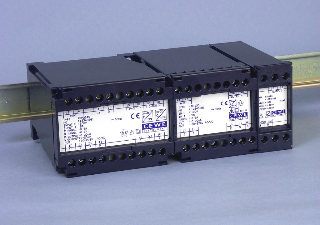
8 GENERAL DESCRIPTION AND TECHNICAL DATA In this catalogue, Cewe Instrument presents BLUE MO- DULE, a wide range of Transducers for DIN-rail and panel mounting. Thanks to high performance and high reliability e. g. a MTBF of 40 years for current transducers, Cewe Instrument transducers have obtained a wide clientele. The transducers are used by industries and power companies in around 40 countries in Europe as well as in all parts of the world. Below follows general information on electrical measuring transducers with eamples of application, definition of terms and some common data for Cewe Instrument transducers. For each group of transducers then follows an eplanation of working principle, block diagram, and general data. The output from our transducers are within certain limits independent of load. The load limits are given in a data sheets. The load independence is obtained by a certain feedback of the output signal to the amplifier. These transducer charactaristics give great advan-tages among which the most important are mentioned below. 1. Measuring values can be transmitted over relatively long distances. 2. Within the framework of the permitted output signal loadings, several measuring or registration units can be connected simultane-ously to the same transducer. No special tuning is required. 3. No adjustment for wire resistance need to be made in P~ Computer DP 134 CL 48 CL 96 B0086 GB connected instruments. 4. The actual wiring is simple and inepensive in that thin wires can be used for output signals. 5. Individual instruments or other measuring or registration units can be disconnected from a circuit after short-circuiting their connection wires. The signal and the remaining units in the circuit remain unaffected which simplifies service. P~ Computer DP 134 CL 48 CL 96 B0087 GB 6. Maimum open circuit output voltage is low, 20 V, which means that the output circuit can be opened without any precautions. 7. They have a wide range of applications because of their high accuracy and the fact that they are approved in accordance wit interference tests IEC and -6, for input and output signals. Certain A/D-converters and controllers require a positive input signal. For this purpose it is useful to have a zero displacement in power measurements with both positive and negative power. Cewe Instrument s transducers can be produced with zero displacement up to 50 % of the measuring range. Eample: Measuring range kw, output signal ma where 4 ma = 100 kw, 12 ma = 0 kw and 20 ma = +100 kw. See page 11 output signal L. P~ R Computer Eample: to a computer. DP 135 CL 48 B0088GB 8
9 GENERAL DESCRIPTION AND TECHNICAL DATA Addition or subtraction of outputs Summation or different measurements are made by connecting the outputs according to the figures below. This is possible because the outputs are potential free. Cewe Instrument s power transducers are adapted for both summation and different measurements. Other Cewe Instrumenttransducers can be used for summation measurements. P~ + + P~ P P P 1 Summation P 1 + P 2 P 2 - P 1 P~ + + P~ P 2 - P1 Difference P 1 P 2 P 2 - B0089 Live-Zero output Using a measuring transducer with a nominal output of 0 20 ma, there can be an uncertainty when the output is zero, whether the in-put quantity is zero or there is a faulty transformer, transducer or connector. To avoid this we produce transducers with a live zero out-put. This output is normally 4 20 ma for an input of %. These live zero output transducers are frequently used in process technology, but could also be used in power distribution instrumentation. Transducer Indicating instrument As previosly mentioned the transducer output is a DC signal and from that follows that one or several moving-coil instruments often serve as the indicating part. In power distribution technology moving-iron instruments are used for indication and measurements. The movingiron is suppressed in the range 0 20 %, while it is practically linear from 20 to 100 %. If a good A.C. measurement in the range 0 20 % is needed, the combination transducer moving-coil instrument is a suitable choice. I~ A Response time The standard response time is 300 ms. A response time of 50 ms is available as an option. (Ecept for DF and DPF) Other response times on request. In this catalogue the concept response time is used to characterize the time performance of the transducer. Time constant is often used in other cases. The diagram below makes clear the difference between response time and time constant. 99 % 63 % Ripple time constant response time The maimum ripple on the output is < 1 % of the output signal (fs) for transducers in class 0.5. The ma. ripple for transducers in class 0.2 is < 0,5 %. t B0224GB 0 B0825 9
10 GENERAL DESCRIPTION AND TECHNICAL DATA Linearity A transducer is linear when the output is proportional to the input. A deviation from a linear function is called a non-linearity error and is epressed as a percentage of a range in our data sheets. Auiliary supply voltage Cewe Instrument transducers with some eceptions are designed for 110 V A.C. or 230 V A.C. ±20 % auiliary supply voltage. Further information on this can be found in the preamble of each transducer type description. Cewe Instrument transducers are also manufactured with a switched power supply in two ranges; V AC/DC (i.e ± 20%) and V AC/DC (i.e ± 20%). In case of auiliary supply with a DC voltage the connection is unaffected by the polarity. Types DU 120 and DI 120 do not require an auiliary power supply. The accuracy class Nominal accuracy class 0.5. Optional 0.2 Cewe Instrument transducers are calibrated to a nominal accuracy value with a maimum error of 0.1% for class 0.2 transducers, and 0.2% for class 0.5 transducers. The reference conditions are a power factor of 1.0. Additional class number factors which influence the accuracy are: Auiliary supply voltage variations The auiliary supply voltage can be varied within wide limits, without any appreciable affection of the measuring accuracy. Measurement error is less than 0,1 % of measuring range. Temperature variations Cewe Instrument transducers are calibrated at an ambient temperature of +23 C. At other temperatures a temperature error has to be added. This error varies between different transducer types. The temperature dependence is separately given in each data sheet. Phase angle variations The phase angle between the current and the voltage is of great importance when measuring the power. The additional error obtained when the phase angle varies is small and is epressed within the indicated class number as a % of the full output signal at ±90º. The values can be found in the product data sheet for the transducer concerned. 10 I ma I Ideal function True function I Non linearity = out 100 [%] I out ma B0100 Casing The casing is made of self-etinguishing polycarbonate. Corresponding to UL 94 V1 Tropical design In environments with a high temperature, high relative humidity and corrosive atmosphere the tropical design gives a good protection. Standard design Tropical design Relative humidity ma 85% Relative humidity ma 95% for ma 60 days per year. for ma 30 days per year. Otherwise ma 75% Otherwise ma 85% Year average ma 65% Year average ma 75% Mounting position The measuring transducers can be mounted in any arbitrary position. The mounting position does not affect the measuring accuracy. Temperature range Under general data for each transducer type, the three temperature ranges are given: working temperature C, function temperature C and storage temperature C. Working temperature range imply the temperature range within which the given data are valid. Function temperature range imply the transducer functions within this range, but can show a somewhat higher temp. coefficient. Storage temperature range imply that the transducer stands to be stored within this temperature interval witout being damaged. Mounting The transducers are mounted easily and quickly on DIN rail type DIN EN A plastic DIN rail, Art No. 4025, can be supplied for mounting single transducers. The rail can easily be cut to the correct length for the relevant case size. See page 59. s The screw terminals are located on the front of the transducer and have a so-called self-opening washer, which facilitates assembly. The terminals can accept a maimum conductor area of mm 2. The transducers are always supplied with protection against accidental contact. Forms of enclosure (Protection degrees) Case seal = IP 51 Terminal part = IP 20
11 Standards Cewe Instrument measurement transducers are tested according to the standards of the EMC Directive and according to IEC and -6 Interference environ-mental classes and test regulations for electronic apparatuses in control equipment for power stations. The transducers are manufactured to IEC EMC directives IEC Emissions light industry IEC Emissions heavy industry IEC Immunity light industry IEC Immunity heavy industry LVD directive IEC IEC Safety Safety For all transducers that are connected to transformers, the secondary side of the transformer must be provided with a protective earth. GENERAL DESCRIPTION AND TECHNICAL DATA signals A B *) C D*) *) Normally the knee point should not be closer than 20 % to the end value. Eample 0 10 ma corresponding to A Live Zero 4 20 ma corresponding to A Suppressed Zero 0 10 ma corresponding to 8 12 kv Suppressed Zero Live Zero 4 20 ma corresponding to 8 12 kv E *) F *) G*) H *) Compressed lower region ma corresponding to kv Compressed lower region live Zero ma corresponding to kv Compressed upper region ma corresponding to A Compressed upper region live zero ma corresponding to A I K L Bipolar ma corresponding to kw Zero displacement ma corresponding to kw Zero displacement ma corresponding to kw B0808GB The maimum load resistance (at current output) is calculated from the formula: RL ma [kω] = 15 [V] ; [ma] 11
12 TRANSDUCERS DU FOR AC VOLTAGE Transducers type DU transforms sinusoidal AC voltage to a proportional load independent DC signal. The input signal can be connected either directly to the transducer, or via a transformer (VT). Transducer type DU 120 does not require auiliary supply. DU 121 to DU 125 Dimensions and weights See page 58 DU 120 U au. ~ U N ~ T1 T2 ~ ~ = = + - B0110GB U N ~ ~ = + - B0692GB Accuracy class *) (Option) Nominal accuracy Non-linearity < 0.2 % < 0.1 % Load dependence < 0.05 % < 0.05 % Response time < 300 ms < 300 ms Au. supply dependence < 0.1 % for U au. ± 20 % < 0.1 % for U au. ± 20 % Temperature coefficient < 0.1 %/10 C < 0.1 %/10 C Ma open circuit output voltage 20 V 20 V Ma output signal by overload *) 125% 125% *) Not DU 120 General data Working temp. range Function temp. range Storage temp. range Test voltage Overload C C C 3.7 kv at U N 300 V 5.55 kv at 300 V < U N < 600 V 1.2 U N continuosly, varistor protection 1.5 U N signals **) A B C D **) The availability of output signal per type, see page 13 and 14 E F G H B0816GB 12
13 TRANSDUCERS DU FOR AC VOLTAGE DU 120 // Kåpa 1 Casing size 1 Gehäuse U~ Ingång//Eingang B0819A DU 120 voltage (U N ) V 1) Burden < 1.2 VA Frequency 50 or 60 Hz Does not require auiliary supply. signal Load resistance R L rated value 1) 1 ma A 0 15 kω 2.5 ma A kω 5 ma A kω 10 ma A kω 20 ma A Ω 1) Other values on request. DU Kåpa 1 Casing size 1 Gehäuse U~ Ingång//Eingang : Väelspänning Auiliary supply: AC voltage : Wechselspannung B0818A DU 121 to 122 voltage (U N ) V 1) Burden 1 ma U N Frequency 16²/ ³, 50/60, 400 Hz signal Load resistance R L rated value 1) 1 ma A, B, C, D 0 15 kω 2.5 ma A, B, C, D kω 5 ma A, B, C, D kω 10 ma A, B, C, D kω 20 ma A, B, C, D Ω 5 V A, C > 2 kω 10 V A, C > 2 kω Auiliary voltage Unit 2) Voltage Frequency Burden V AC Hz 2 VA V AC Hz 2 VA 1) Other values on request. 2) Third digit in the type designition, shows type of auiliary supply. 13
14 TRANSDUCERS DU FOR AC VOLTAGE DU 124 to 125 voltage (U N ) V 1) Burden 1 ma U N Frequency 16²/ ³, 50/60, 400 Hz U~ DU Kåpa 3/Casing size 3/Gehäuse Ingång//Eingang : Lik-/väelspänning Auiliary supply: AC/DC voltage : Gleich-/Wechselspannung B0817F signal 2) Load resistance R L rated value 1) 1 ma A, B, C, D, E, F, G, H 0 15 kω 2.5 ma A, B, C, D, E, F, G, H kω 5 ma A, B, C, D, E, F, G, H kω 10 ma A, B, C, D, E, F, G, H kω 20 ma A, B, C, D, E, F, G, H Ω 5 V A, C, E, G > 2 kω 10 V A, C, E, G > 2 kω Auiliary voltage Unit 3) Voltage Frequency Burden V AC/DC Hz or DC 4 VA/2.5 W V AC/DC Hz or DC 4 VA/2.5 W 1) Other values on request. 2) Curve E, F: Min. supressed lower region is 0-20 % of ma input value. Curve G, H: Ma. supressed upper region is % of ma input. 3) Third digit in the type designition, shows type of auiliary supply value. 14
15 TRANSDUCERS DU FOR AC VOLTAGE Ordering form DU DU (Voltage AC) Default Eample 1 Eample 2 Type: DU 122 DU 122 Accuracy: cl Transf. ratio voltage: 11000/110 V 11000/110 V Frequency: 50 Hz 50 Hz 50 Hz Measuring range: 0-13,2 kv kv signal: V V : 4-20 ma ma curve: B E Response time: 300 ms 300 ms 300 ms Auiliary supply: V AC V AC 15
16 TRANSDUCERS DI FOR AC CURRENT Transducers type DI transform sinusoidal AC current to a proportional load independent DC signal. The input signal can be connected either directly to the transducer, or via a transformer. Transducer DI 11 does not require auiliary supply. DI 121 to DI 125 Dimensions and weights See page 58 DI 120 U au. ~ I N ~ T1 T2 ~ ~ = = + - B0115GB I N ~ ~ = + - B0425GB Accuracy class *) (Option) Nominal accuracy Non-linearity < 0.2 % < 0.1 % Load dependence < 0.05 % < 0.05 % Response time < 300 ms < 300 ms Au. supply dependence < 0.1 % for U au. ± 20 % < 0.1 % for U au. ± 20 % Temperature coefficient < 0.1 %/10 C < 0.1 %/10 C Ma open circuit output voltage 20 V 20 V Ma output signal by overload *) 125% 125% *) Not DI 120 General data Working temp. range Function temp. range Storage temp. range Test voltage Overload C C C 3,7 kv Standard (U N < 300 V), 5,55 kv, Option (300 V < U N < 600 V) 2 I N continuosly, 10 I N during 10 s, 40 I N during 1 s signals **) A B C D **) The availability of output signal per type, see page 17 and 18 E F G H B0816GB 16
17 TRANSDUCERS DI FOR AC CURRENT DI 120 // Kåpa 1 Casing size 1 Gehäuse 1 DI 120 current (I N ) 1.0, 1.2, 5.0, 6.0 A 1) Burden < 0,25 to < 1.2 VA Frequency 50/60 Hz at Class 0.5 Does not require auiliary supply. 1 3 I~ Ingång//Eingang B0823A signal Load resistance R L rated value 1) 1 ma A 0 15 kω 2.5 ma A kω 5 ma A kω 10 ma A kω 20 ma A Ω 1) Other values on request. DI : Väelspänning Auiliary supply: AC voltage : Wechselspannung Kåpa 1 Casing size 1 Gehäuse I~ Ingång//Eingang B0822A DI 121 to 122 current (I N ) 1.0, 1.2, 2.0, 2.4, 5.0, 6.0 A 1) Burden < 0.04 to < 0.2 VA Frequency 16²/ ³, 50/60, 400 Hz signal Load resistance R L rated value 1) 1 ma A, B, C, D 0 15 kω 2.5 ma A, B, C, D kω 5 ma A, B, C, D kω 10 ma A, B, C, D kω 20 ma A, B, C, D Ω 5 V A, C > 2 kω 10 V A, C > 2 kω Auiliary voltage Unit 2) Voltage Frequency Burden V AC Hz 2 VA V AC Hz 2 VA 1) Other values on request. 2) Third digit in the type designition, shows type of auiliary supply. 17
18 TRANSDUCERS DI FOR AC CURRENT DI 124 to 125 current (I N ) 1.0, 1.2, 2.0, 2.4, 5.0, 6.0 A 1) Burden < 0.04 to < 0.2 VA Frequency 16²/ ³, 50/60, 400 Hz DI Kåpa 3/Casing size 3/Gehäuse I~ Ingång//Eingang : Lik-/väelspänning Auiliary supply: AC/DC voltage : Gleich-Wechelspannung B0821B signal 2) Load resistance R L rated value 1) 1 ma A, B, C, D, E, F, G, H 0 15 kω 2.5 ma A, B, C, D, E, F, G, H kω 5 ma A, B, C, D, E, F, G, H kω 10 ma A, B, C, D, E, F, G, H kω 20 ma A, B, C, D, E, F, G, H Ω 5 V A, C, E, G > 2 kω 10 V A, C, E, G > 2 kω 1) Other values on request. 2) Curve E, F: Min. supressed lower region is 0-20 % of ma input value. Curve G, H: Ma. supressed upper region is % of ma input. 3) Third digit in the type designition, shows type of auiliary supply value. Auiliary voltage Unit 3) Voltage Frequency Burden V AC/DC Hz or DC 4 VA/2.5 W V AC/DC Hz or DC 4 VA/2.5 W Ordering form DI DI (Current AC) Default Eample 1 Eample 2 Type: DI 125 DI 120 Accuracy: cl Transf. ratio current: 100/5 A 100/5 A Frequency: 50 Hz 50 Hz 50 Hz Measuring range: A A signal: 0-6 A 0-6 A : 4-20 ma 0-20 ma curve: B A Response time: 300 ms 300 ms 300 ms Auiliary supply: V AC/DC 18
19 TRANSDUCERS DUD FOR DC VOLTAGE AND DID FOR DC CURRENT Transducers type DUD and DID are used to measure DC voltage and DC current that are converted into a proportional load-independent galvanic isolated DC voltage or DC current signal. Dimensions and weights See page 58 U AUX T1 ~ ~ Type DUD U N = + - / T1 ~ Type DID U AUX ~ I N = + - / B0730GB data Accuracy class (Option) Linearity error < 0.2 % <0.1 % Load-dependence <0.05 % <0.05 % Response time (0-99%) ms ms Auiliary voltage dependence < 0.1 % < 0.1 % Temperature dependence < 0.1 %/10 C < 0.06 %/10 C Ma voltage with open output 20 V 20 V Ma output signal with over-driven input signal <125 % <125 % Ripple (peak-to-peak) <1.0 % <0.5 % General data Working temp. range C Function temp. range C Storage temp. range C Test voltage 5.55 kv, 50 Hz signals A B C D I K L B0857GB 19
20 TRANSDUCERS DUD FOR DC VOLTAGE AND DID FOR DC CURRENT DUD 124 to 125, DC voltage data Measured voltage (U N ) resistance 0 60 mv V 40 kω/v measuring range 0 0,5 V 10 kω/v measuring range V DUD Kåpa 3/Casing size 3/Gehäuse Ingång//Eingang B0856E signal 1) Curve Load resistance R L 0 1 ma A, B, C, D, I, K, L 0 15 kω 0 2 ma A, B, C, D, I, K, L kω 0 2,5 ma A, B, C, D, I, K, L kω 0 5 ma A, B, C, D, I, K, L kω 0 10 ma A, B, C, D, I, K, L 0 1,5 kω 0 20 ma A, B, C, D, I, K, L Ω 4 20 ma A, B, C, D, I, K, L Ω 0 1 V A, B, C, D, I, K, L > 2 kω 0 2 V A, B, C, D, I, K, L > 2 kω 0 5 V A, B, C, D, I, K, L > 2 kω 0 10 V A, B, C, D, I, K, L > 2 kω 1) Other values on request. 2) Third digit in the type designition, shows type of auiliary supply. Auiliary voltage Unit 2) Voltage Frequency Burden V AC/DC Hz or DC 4 VA/2.5 W V AC/DC Hz or DC 4 VA/2.5 W DID 124 to 125, DC current data Measuring current (I N ) 0 1 ma ma Shunt voltage ma 0,15 V DID Kåpa 3/Casing size 3/Gehäuse Ingång//Eingang B0856F signal 1) Curve Load resistance R L 0 1 ma A, B, C, D, I, K, L 0 15 kω 0 2 ma A, B, C, D, I, K, L kω 0 2,5 ma A, B, C, D, I, K, L kω 0 5 ma A, B, C, D, I, K, L kω 0 10 ma A, B, C, D, I, K, L 0 1,5 kω 0 20 ma A, B, C, D, I, K, L Ω 4 20 ma A, B, C, D, I, K, L Ω 0 1 V A, B, C, D, I, K, L > 2 kω 0 2 V A, B, C, D, I, K, L > 2 kω 0 5 V A, B, C, D, I, K, L > 2 kω 0 10 V A, B, C, D, I, K, L > 2 kω 1) Other values on request. 2) Third digit in the type designition, shows type of auiliary supply. Auiliary voltage Unit 2) Voltage Frequency Burden V AC/DC Hz or DC 4 VA/2.5 W V AC/DC Hz or DC 4 VA/2.5 W 20
21 TRANSDUCERS DUD FOR DC VOLTAGE AND DID FOR DC CURRENT Ordering form DUD DUD (Voltage DC) Default Eample Type: DUD 125 Accuracy: cl signal: : curve: 0-60 mv 0-20 ma A Response time: 300 ms 300 ms Auiliary supply: V AC/DC Ordering form DID DID (Current DC) Default Eample Type: DID 124 Accuracy: cl signal: : curve: 4-20 ma 4-20 ma B Response time: 300 ms 300 ms Auiliary supply: V AC/DC 21
22 TRANSDUCERS DF FOR FREQUENCY Transducers type DF are used for the measurement of the frequency of an AC voltage and transforms it into a proportionally load independent DC signal. The input can be connected directly or via a transformer. Dimensions and weights See page 58 U au. ~ U N ~ Microprocessor B1040GB Accuracy class 0.1 Non-linearity < 0.05 % Load dependence < 0.05 % (within load limits) Response time < 300 ms Au. supply dependence < 0.05 % for U au. ± 20 % Temperature coefficient < 0.1 %/ 10 C Ma open circuit output voltage 20 V General data Working temp. range Function temp. range Storage temp. range Test voltage Overload capacity C C C 3.75 kv, 50 Hz U N 2, rated for 1 sec signals A B B0855GB 22
23 TRANSDUCERS DF FOR FREQUENCY single output U~ Ingång//Eingang 11 2 Kåpa 3/Casing size 3/Gehäuse 3 DF 125, DF 125, 127 voltage (U N ) Working range Power consumption Auiliary supply Voltage DF 125 Power consumption Voltage DF 127 Power consumption V ( ) U N < 0.5 VA V AC(45-65 Hz) / DC < 8.0 VA/<4.0 W V DC(±20%) < 4.0 VA B0828D Measuring range Hz dual output Hz Hz Ingång//Eingang Hz U~ 11 2 Kåpa 3/Casing size 3/Gehäuse 3 DF 125, B0828E signal 1) Curve Load resistance R L 0 10 ma A Ω 0 20 ma A Ω 4 20 ma B Ω 0 10 V A > 2 kω 0 5 V A > 2 kω 1 5 V B > 2 kω 1) Other values on request. Ordering form DF DF (Frequency) Default Eample Type: DF 125 Accuracy: cl Measuring range: Voltage: 1: curve 1: Hz 110 V 0-10 ma A 2: curve 2: Auiliary supply: 110 V DC 23

24 TRANSDUCERS FOR POWER FACTOR Our programmable transducer DPT can be used for measuring power factor, see separate product presentation. 24
25 TRANSDUCERS FOR POWER FACTOR Brief description The Programmable Transducer type DPT has in a fully equipped version; four analogue channels for any instantaneous measured value, with a output signal of ma or V, galvanic insulated from each other and from the input signals, two digital pulse outputs for energy and a Modbus RTU with all measured values available. Easy programmed with the belonging software CofigView connected with a standard USB cable. Available as ConfigView or as a ConfigView kit, software and USB cable. The Transducer is meant for DIN rail mounting and has the dimensions ,4 113,8 mm (h w d) The Transducer is designed according to the standard IEC and reaches the accuracy class 0.2 or 0.5 as per your order. All essential measuring values can be programmed to the outputs and are available through Modbus communication, the connection of the input signals can be freely programmed for single phase, 3 phase 3 wire as well as 3 phase 4 wire and for both balanced and unbalanced load. Both input voltage and input current as well as auiliary supply are of wide range type. See separate product presentation. 25
26 TRANSDUCERS DP, DQ AND DPQ FOR ACTIVE AND REACTIVE POWER Transducer type DP, DQ and DPQ measures the active (P) and reactive (Q) A.C.-power and converts these into proportional load-independent DC current signals. The measurement principle for multiplication of the current and the voltage is based on the TDM (Time-Division-Multiplication) method. The measurement principle also takes account of the curve form error and the phase angle difference ( ϕ = ) between the current and the voltage and gives the true power value (true RMS) as its result. In transducer DPQ the signal outputs (P) and (Q) are galvanically separated from one another. The measurement voltage and measurement current can be connected directly to the transducer or via measurement transformers. The permitted value for the scale factor shall lie within the range and shall be defined by the scale factor formula. The current may not eceed 10 A. Scale factor Measuring range [W or Var] = (Normally ) Nominal apparent power [VA] U Au U Au U N ~ I N ~ U N ~ T1 T2 T1 T2 T3 = = DP, DQ + - DPQ + - P B0768GB General data Working temp. range Function temp. range Storage temp. range Test voltage Overload C Fundamental circuit C C 5.55 kv, 50 Hz (measurement input signal/outputs) 3.7 kv, 50 Hz (auiliary voltage input signal/outputs) 1.5 kv, 50 Hz (signal output (P) signal output (Q) 1.2 U N continuous, varistor protection 1.5 U N 2 I N continuous, 10 I N during 10 s, 40 I N during 1 s I N ~ T3 + - Q B0850GB Dimensions and weights See page 58 data Accuracy class (option) Nominal accuracy Linearity error < 0.2 % < 0.1 % Load-dependence < 0,05 % < 0,05 % Response time (T 99 ) < 300 ms < 300 ms Auiliary voltage dependence < 0.1 % < 0.1 % Temperature dependence < 0.2 %/10 C < 0.2 %/10 C Ma voltage with open output 20 V 20 V Ma output signal with over-driven signal <125% <125% Linearity A transducer is linear when the output is proportional to the input. A deviation from a linear function is called a non-linearity error and is epressed as a percentage of a range in our data sheets. I ma I Ideal function True function I Non linearity = out 100 [%] I out ma B
27 Product range summary The models of measuring transducers available for measuring the active power are shown in the table. Configuration of the measuring transducer with regard to the output rated value and the desired functional curve are shown in the tables and diagram on page TRANSDUCERS DP FOR ACTIVE POWER Designition Number of System Auiliary Casing mesuring supply size elements DP E, 1.phase/2-wire, (ph/n) V AC/DC 3 DP E, 1.phase/2-wire, (ph/n) V AC/DC 3 DP E, 3-wire, balanced load V AC/DC 3 DP E, 3-wire, balanced load V AC/DC 3 DP E, 4-wire, (ph/n), balanced load V AC/DC 3 DP E, 4-wire, (ph/n), balanced load V AC/DC 3 DP E, 3-wire, unbalanced load V AC/DC 3 DP E, 3-wire, unbalanced load V AC/DC 3 DP E, 3-wire or 4-wire V AC/DC 4 DP E, 3-wire or 4-wire V AC/DC 4 DP E, 4-wire, unbalanced load V AC/DC 4 DP E, 4-wire, unbalanced load V AC/DC 4 Auiliary voltage Unit *) Voltage Frequency Burden V AC/DC Hz or DC 4 VA/2.5 W V AC/DC Hz or DC 4 VA/2.5 W *) Third digit in the type designition, shows type of auiliary supply. 27
28 TRANSDUCERS DP FOR ACTIVE POWER signals A B I K L B0809GB 28
29 TRANSDUCERS DP FOR ACTIVE POWER DP Kåpa 3/Casing size 3/Gehäuse 3 DP 124 to 125 data Measurement voltage (U N ) 40 to 600 V 1) 1 ma per phase U N Measurement current (I N ) 1, 2, 5 A 1) <0.1 VA per phase Frequency 16²/ ³, 50, 60, 400 Hz The maimum load resistance (at current output) is calculated from the formula: N k l R L ma [kω] = 15 [V] current [ma] Lågspänningssystem Low voltage system Niederspannungssystem DP Kåpa 3/Casing size 3/Gehäuse 3 B0792B signal Load resistance R L rated value 1) 1 ma A, B, I, K, L 0 15 kω 2 ma A, B, I, K, L 0 7,5 kω 2,5 ma A, B, I, K, L 0 6 kω 5 ma A, B, I, K, L 0 3 kω 10 ma A, B, I, K, L kω 20 ma A, B, I, K, L Ω 1 V A, I, K > 2 kω 2 V A, I, K > 2 kω 5 V A, I, K > 2 kω 10 V A, I, K > 2 kω u v k l 1) Other values on request. N U V Högspänningssystem High voltage system Hochspannungssystem B0793B 29
30 TRANSDUCERS DP FOR ACTIVE POWER DP Kåpa 3/Casing size 3/Gehäuse 3 DP 134 to 135 data Measurement voltage (U N ) 40 to 600 V 1) 1 ma per phase U N Measurement current (I N ) 1, 2, 5 A 1) <0.1 VA per phase Frequency 16²/ ³, 50, 60, 400 Hz The maimum load resistance (at current output) is calculated from the formula: L2 L3 k l Lågspänningssystem Low voltage system Niederspannungssystem B0796B R L ma [kω] = 15 [V] current [ma] U L2 L3 u v V u U DP v k V l Kåpa 3/Casing size 3/Gehäuse 3 Högspänningssystem High voltage system Hochspannungssystem B0797B signal Load resistance R L rated value 1) 1 ma A, B, I, K, L 0 15 kω 2 ma A, B, I, K, L 0 7,5 kω 2,5 ma A, B, I, K, L 0 6 kω 5 ma A, B, I, K, L 0 3 kω 10 ma A, B, I, K, L kω 20 ma A, B, I, K, L Ω 1 V A, I, K > 2 kω 2 V A, I, K > 2 kω 5 V A, I, K > 2 kω 10 V A, I, K > 2 kω 1) Other values on request. 30
31 TRANSDUCERS DP FOR ACTIVE POWER DP Kåpa 3/Casing size 3/Gehäuse 3 DP 144 to 145 data Measurement voltage (U N ) 40 to 600 V 1) 1 ma per phase U N Measurement current (I N ) 1, 2, 5 A 1) <0.1 VA per phase Frequency 16²/ ³, 50, 60, 400 Hz L2 L3 N u U L2 L3 N k l Lågspänningssystem Low voltage system Niederspannungssystem DP v k V l Kåpa 3/Casing size 3/Gehäuse 3 Högspänningssystem High voltage system Hochspannungssystem B0794B B0795B The maimum load resistance (at current output) is calculated from the formula: R L ma [kω] = 15 [V] current [ma] signal Load resistance R L rated value 1) 1 ma A, B, I, K, L 0 15 kω 2 ma A, B, I, K, L 0 7,5 kω 2,5 ma A, B, I, K, L 0 6 kω 5 ma A, B, I, K, L 0 3 kω 10 ma A, B, I, K, L kω 20 ma A, B, I, K, L Ω 1 V A, I, K > 2 kω 2 V A, I, K > 2 kω 5 V A, I, K > 2 kω 10 V A, I, K > 2 kω 1) Other values on request. 31
32 TRANSDUCERS DP FOR ACTIVE POWER DP Kåpa 3/Casing size 3/Gehäuse 3 DP 234 to 235 data Measurement voltage (U N ) 40 to 600 V 1) 1 ma per phase U N Measurement current (I N ) 1, 2, 5 A 1) <0.1 VA per phase Frequency 16²/ ³, 50, 60, 400 Hz The maimum load resistance (at current output) is calculated from the formula: L2 L3 k l k l R L ma [kω] = 15 [V] current [ma] Lågspänningssystem Low voltage system Niederspannungssystem DP Kåpa 3/Casing size 3/Gehäuse B0798B signal Load resistance R L rated value 1) 1 ma A, B, I, K, L 0 15 kω 2 ma A, B, I, K, L 0 7,5 kω 2,5 ma A, B, I, K, L 0 6 kω 5 ma A, B, I, K, L 0 3 kω 10 ma A, B, I, K, L kω 20 ma A, B, I, K, L Ω 1 V A, I, K > 2 kω 2 V A, I, K > 2 kω 5 V A, I, K > 2 kω 10 V A, I, K > 2 kω U L2 L3 u v V u U v k l V k l 1) Other values on request. Högspänningssystem High voltage system Hochspannungssystem B0799B 32
33 TRANSDUCERS DP FOR ACTIVE POWER L2 L3 N DP Kåpa 4/Casing size 4/Gehäuse k l k l k l Lågspänningssystem Low voltage system Niederspannungssystem DP Kåpa 4/Casing size 4/Gehäuse B0851B DP 334 to 335 data Measurement voltage (U N ) 40 to 600 V 1) 1 ma per phase U N Measurement current (I N ) 1, 2, 5 A 1) <0.1 VA per phase Frequency 16²/ ³, 50, 60, 400 Hz The maimum load resistance (at current output) is calculated from the formula: R L ma [kω] = 15 [V] current [ma] signal Load resistance R L rated value 1) 1 ma A, B, I, K, L 0 15 kω 2 ma A, B, I, K, L 0 7,5 kω 2,5 ma A, B, I, K, L 0 6 kω 5 ma A, B, I, K, L 0 3 kω 10 ma A, B, I, K, L kω 20 ma A, B, I, K, L Ω 1 V A, I, K > 2 kω 2 V A, I, K > 2 kω 5 V A, I, K > 2 kω 10 V A, I, K > 2 kω U L2 L3 N u v V u U v k l k l k l V Högspänningssystem High voltage system Hochspannungssystem B0852B 1) Other values on request. 33
34 TRANSDUCERS DP FOR ACTIVE POWER L2 L3 N u u u X X X U U U L2 L3 N k l k l k l H älpspänning Uau supply Hil sspannung DP Kåpa 4/Casing size 4/Gehäuse 4 Lågspänningssystem Low voltage system Niederspannungssystem DP Kåpa 4/Casing size 4/Gehäuse k l k l k l Högspänningssystem High voltage system Hochspannungssystem B0800B B0801B DP 344 to 345 data Measurement voltage (U N ) 40 to 600 V 1) 1 ma per phase U N Measurement current (I N ) 1, 2, 5 A 1) <0.1 VA per phase Frequency 16²/ ³, 50, 60, 400 Hz The maimum load resistance (at current output) is calculated from the formula: R L ma [kω] = 1) Other values on request. 15 [V] current [ma] signal Load resistance R L rated value 1) 1 ma A, B, I, K, L 0 15 kω 2 ma A, B, I, K, L 0 7,5 kω 2,5 ma A, B, I, K, L 0 6 kω 5 ma A, B, I, K, L 0 3 kω 10 ma A, B, I, K, L kω 20 ma A, B, I, K, L Ω 1 V A, I, KL > 2 kω 2 V A, I, K > 2 kω 5 V A, I, K > 2 kω 10 V A, I, K > 2 kω 34
35 TRANSDUCERS DP FOR ACTIVE POWER Ordering form DP DP (Active power) Default Eample Type: DP 235 Accuracy: cl Transf. ratio voltage: Transf. ratio current: 11000/110 V 100/5 A Frequency: 50 Hz 50 Hz Measuring range (P): (P): curve: 0-2 MW 4-20 ma B Response time: 300 ms 300 ms Auiliary supply: V AC/DC 35
36 TRANSDUCERS DQ FOR REACTIVE POWER Product range summary The models of measuring transducers available for measuring the reactive power are shown in the table. Configuration of the measuring transducer with regard to the output rated value and the desired functional curve are shown in the tables and diagram on page Designition Number of System Auiliary Casing mesuring supply size elements DQ E, 3-wire, balanced load V AC/DC 3 DQ E, 3-wire, balanced load V AC/DC 3 DQ E, 3-wire, unbalanced load V AC/DC 3 DQ E, 3-wire, unbalanced load V AC/DC 3 DQ E, 3-wire or 4-wire V AC/DC 4 DQ E, 3-wire or 4-wire V AC/DC 4 DQ E, 4-wire, unbalanced load V AC/DC 4 DQ E, 4-wire, unbalanced load V AC/DC 4 Auiliary voltage Unit *) Voltage Frequency Burden V AC/DC Hz or DC 4 VA/2.5 W V AC/DC Hz or DC 4 VA/2.5 W *) Third digit in the type designition, shows type of auiliary supply. 36
37 TRANSDUCERS DQ FOR REACTIVE POWER signals A B I K L B0809GB 37
38 TRANSDUCERS DQ FOR REACTIVE POWER DQ Kåpa 3/Casing size 3/Gehäuse 3 DQ 134 to 135 data Measurement voltage (U N ) 40 to 600 V 1) 1 ma per phase U N Measurement current (I N ) 1, 2, 5 A 1) <0.1 VA per phase Frequency 16²/ ³, 50, 60, 400 Hz The maimum load resistance (at current output) is calculated from the formula: L2 L3 k l R L ma [kω] = 15 [V] current [ma] Lågspänningssystem Low voltage system Niederspannungssystem DQ Kåpa 3/Casing size 3/Gehäuse B0802B signal Load resistance R L rated value 1) 1 ma A, B, I, K, L 0 15 kω 2 ma A, B, I, K, L 0 7,5 kω 2,5 ma A, B, I, K, L 0 6 kω 5 ma A, B, I, K, L 0 3 kω 10 ma A, B, I, K, L kω 20 ma A, B, I, K, L Ω 1 V A, I, K > 2 kω 2 V A, I, K > 2 kω 5 V A, I, K > 2 kω 10 V A, I, K > 2 kω 1) Other values on request. u v k l L2 L3 U V Högspänningssystem High voltage system Hochspannungssystem B0803B 38
39 TRANSDUCERS DQ FOR REACTIVE POWER DQ Kåpa 3/Casing size 3/Gehäuse DQ 234 to 235 data Measurement voltage (U N ) 40 to 600 V 1) 1 ma per phase U N Measurement current (I N ) 1, 2, 5 A 1) <0.1 VA per phase Frequency 16²/ ³, 50, 60, 400 Hz The maimum load resistance (at current output) is calculated from the formula: L2 L3 k l k l R L ma [kω] = 15 [V] current [ma] Lågspänningssystem Low voltage system Niederspannungssystem DQ Kåpa 3/Casing size 3/Gehäuse B0804B signal Load resistance R L rated value 1) 1 ma A, B, I, K, L 0 15 kω 2 ma A, B, I, K, L 0 7,5 kω 2,5 ma A, B, I, K, L 0 6 kω 5 ma A, B, I, K, L 0 3 kω 10 ma A, B, I, K, L kω 20 ma A, B, I, K, L Ω 1 V A, I, K > 2 kω 2 V A, I, K > 2 kω 5 V A, I, K > 2 kω 10 V A, I, K > 2 kω 1) Other values on request. U L2 L3 u v V u U v k l k l V Högspänningssystem High voltage system Hochspannungssystem B0805B 39
40 TRANSDUCERS DQ FOR REACTIVE POWER L2 L3 N DQ Kåpa 4/Casing size 4/Gehäuse k l k l k l Lågspänningssystem Low voltage system Niederspannungssystem DQ Kåpa 4/Casing size 4/Gehäuse B0853B DQ 334 to 335 data Measurement voltage (U N ) 40 to 600 V 1) 1 ma per phase U N Measurement current (I N ) 1, 2, 5 A 1) <0.1 VA per phase Frequency 16²/ ³, 50, 60, 400 Hz The maimum load resistance (at current output) is calculated from the formula: R L ma [kω] = 1) Other values on request. 15 [V] current [ma] signal Load resistance R L rated value 1) 1 ma A, B, I, K, L 0 15 kω 2 ma A, B, I, K, L 0 7,5 kω 2,5 ma A, B, I, K, L 0 6 kω 5 ma A, B, I, K, L 0 3 kω 10 ma A, B, I, K, L kω 20 ma A, B, I, K, L Ω 1 V A, I, K > 2 kω 2 V A, I, K > 2 kω 5 V A, I, K > 2 kω 10 V A, I, K > 2 kω L2 L3 N U u v V u U v k l k l k l V Högspänningssystem High voltage system Hochspannungssystem B0854B 40
41 TRANSDUCERS DQ FOR REACTIVE POWER L2 L3 N DQ Kåpa 4/Casing size 4/Gehäuse k l k l k l H älpspänning Uau supply Hil sspannung Lågspänningssystem Low voltage system Niederspannungssystem DQ Kåpa 4/Casing size 4/Gehäuse utput usgang B0806B DQ 344 to 345 data Measurement voltage (U N ) 40 to 600 V 1) 1 ma per phase U N Measurement current (I N ) 1, 2, 5 A 1) <0.1 VA per phase Frequency 16²/ ³, 50, 60, 400 Hz The maimum load resistance (at current output) is calculated from the formula: R L ma [kω] = 15 [V] current [ma] signal Load resistance R L rated value 1) 1 ma A, B, I, K, L 0 15 kω 2 ma A, B, I, K, L 0 7,5 kω 2,5 ma A, B, I, K, L 0 6 kω 5 ma A, B, I, K, L 0 3 kω 10 ma A, B, I, K, L kω 20 ma A, B, I, K, L Ω 1 V A, I, K > 2 kω 2 V A, I, K > 2 kω 5 V A, I, K > 2 kω 10 V A, I, K > 2 kω 1) Other values on request. L2 L3 N u u u X X X U U U k l k l k l Högspänningssystem High voltage system Hochspannungssystem B0807B 41
42 TRANSDUCERS DQ FOR REACTIVE POWER Ordering form DQ DQ (Reactive power) Default Eample Type: DQ 235 Accuracy: cl Transf. ratio voltage: Transf. ratio current: 11000/110 V 100/5 A Frequency: 50 Hz 50 Hz Measuring range (Q): (Q): curve: 0-2 Mvar 4-20 ma B Response time: 300 ms 300 ms Auiliary supply: V AC 42
43 Product range summary TRANSDUCERS DPQ FOR ACTIVE AND REACTIVE POWER The models of measuring transducers available for measuring the active and reactive power are shown in the table. Configuration of the measuring transducer with regard to the output rated value and the desired functional curve are shown in the tables and diagram on page Designition Number of System Auiliary Casing mesuring supply size elements DPQ E, 3-wire, balanced load V AC/DC 4 DPQ E, 3-wire, balanced load V AC/DC 4 DPQ E, 4-wire, balanced load V AC/DC 4 DPQ E, 4-wire, balanced load V AC/DC 4 DPQ E, 3-wire, unbalanced load V AC/DC 4 DPQ E, 3-wire, unbalanced load V AC/DC 4 DPQ E, 3-wire or 4-wire V AC/DC 4 DPQ E, 3-wire or 4-wire V AC/DC 4 DPQ E, 4-wire, unbalanced load V AC/DC 4 DPQ E, 4-wire, unbalanced load V AC/DC 4 Auiliary voltage Unit *) Voltage Frequency Burden V AC/DC Hz or DC 4 VA/2.5 W V AC/DC Hz or DC 4 VA/2.5 W *) Third digit in the type designition, shows type of auiliary supply. 43
44 TRANSDUCERS DPQ FOR ACTIVE AND REACTIVE POWER signals A B I K L B0809GB 44
45 TRANSDUCERS DPQ FOR ACTIVE AND REACTIVE POWER L2 L3 K DPQ k l L Kåpa 4/Casing size 4/Gehäuse P Q Lågspänningssystem Low voltage system Niederspannungssystem DPQ P Q Kåpa 4/Casing size 4/Gehäuse B0751B DPQ 134 to 135 data Measurement voltage (U N ) 40 to 600 V 1) 1 ma per phase U N Measurement current (I N ) 1, 2, 5 A 1) <0.1 VA per phase Frequency 16²/ ³, 50, 60, 400 Hz The maimum load resistance (at current output) is calculated from the formula: R L ma [kω] = 1) Other values on request. 15 [V] current [ma] signal Load resistance R L rated value 1) 1 ma A, B, I, K, L 0 15 kω 2 ma A, B, I, K, L 0 7,5 kω 2,5 ma A, B, I, K, L 0 6 kω 5 ma A, B, I, K, L 0 3 kω 10 ma A, B, I, K, L kω 20 ma A, B, I, K, L Ω 1 V A, I, K > 2 kω 2 V A, I, K > 2 kω 5 V A, I, K > 2 kω 10 V A, I, K > 2 kω U L2 L3 u v V u U v V K k l L Högspänningssystem High voltage system Hochspannungssystem B0753B 45
46 TRANSDUCERS DPQ FOR ACTIVE AND REACTIVE POWER L2 L3 N L2 L3 N K u u u X X X U U U DPQ k l L Kåpa 4/Casing size 4/Gehäuse Lågspänningssystem Low voltage system Niederspannungssystem V K P Q DPQ k l L Kåpa 4/Casing size 4/Gehäuse Högspänningssystem High voltage system Hochspannungssystem P Q B0754B B0755B DPQ 144 to 145 data Measurement voltage (U N ) 40 to 600 V 1) 1 ma per phase U N Measurement current (I N ) 1, 2, 5 A 1) <0.1 VA per phase Frequency 16²/ ³, 50, 60, 400 Hz The maimum load resistance (at current output) is calculated from the formula: R L ma [kω] = 1) Other values on request. 15 [V] current [ma] signal Load resistance R L rated value 1) 1 ma A, B, I, K, L 0 15 kω 2 ma A, B, I, K, L 0 7,5 kω 2,5 ma A, B, I, K, L 0 6 kω 5 ma A, B, I, K, L 0 3 kω 10 ma A, B, I, K, L kω 20 ma A, B, I, K, L Ω 1 V A, I, K > 2 kω 2 V A, I, K > 2 kω 5 V A, I, K > 2 kω 10 V A, I, K > 2 kω 46
47 TRANSDUCERS DPQ FOR ACTIVE AND REACTIVE POWER DPQ P Q Kåpa 4/Casing size 4/Gehäuse 4 DPQ 234 to 235 data Measurement voltage (U N ) 40 to 600 V 1) 1 ma per phase U N Measurement current (I N ) 1, 2, 5 A 1) <0.1 VA per phase Frequency 16²/ ³, 50, 60, 400 Hz L2 L k l k l K L The maimum load resistance (at current output) is calculated from the formula: R L ma [kω] = 15 [V] current [ma] U L2 L3 u v V u U DPQ v Lågspänningssystem Low voltage system Niederspannungssystem V K k l Kåpa 4/Casing size 4/Gehäuse L P Q K k Högspänningssystem High voltage system Hochspannungssystem l L B0756B B0757B signal Load resistance R L rated value 1) 1 ma A, B, I, K, L 0 15 kω 2 ma A, B, I, K, L 0 7,5 kω 2,5 ma A, B, I, K, L 0 6 kω 5 ma A, B, I, K, L 0 3 kω 10 ma A, B, I, K, L kω 20 ma A, B, I, K, L Ω 1 V A, I, K > 2 kω 2 V A, I, K > 2 kω 5 V A, I, K > 2 kω 10 V A, I, K > 2 kω 1) Other values on request. 47
48 TRANSDUCERS DPQ FOR ACTIVE AND REACTIVE POWER L2 L3 N K k DPQ l L k K l L K Kåpa 4/Casing size 4/Gehäuse 4 Lågspänningssystem Low voltage system Niederspannungssystem k DPQ P Q l L P Q Kåpa 4/Casing size 4/Gehäuse B0758B DPQ 334 to 335 data Measurement voltage (U N ) 40 to 600 V 1) 1 ma per phase U N Measurement current (I N ) 1, 2, 5 A 1) <0.1 VA per phase Frequency 16²/ ³, 50, 60, 400 Hz The maimum load resistance (at current output) is calculated from the formula: R L ma [kω] = 15 [V] current [ma] signal Load resistance R L rated value 1) 1 ma A, B, I, K, L 0 15 kω 2 ma A, B, I, K, L 0 7,5 kω 2,5 ma A, B, I, K, L 0 6 kω 5 ma A, B, I, K, L 0 3 kω 10 ma A, B, I, K, L kω 20 ma A, B, I, K, L Ω 1 V A, I, K > 2 kω 2 V A, I, K > 2 kω 5 V A, I, K > 2 kω 10 V A, I, K > 2 kω 1) Other values on request. U L2 L3 N u v V u U v V K k l L K k l L K Högspänningssystem High voltage system Hochspannungssystem k l L B0759B 48
49 TRANSDUCERS DPQ FOR ACTIVE AND REACTIVE POWER L2 L3 N L2 L3 N K k H älpspänning au supply Hil sspannung u u u K DPQ l L k K l L K Kåpa 4/Casing size 4/Gehäuse 4 Lågspänningssystem Low voltage system Niederspannungssystem k DPQ k l L K P Q l L Kåpa 4/Casing size 4/Gehäuse k l L K Högspänningssystem High voltage system Hochspannungssystem tgång utput usgang - - k l L B0760B B0761B DPQ 344 to 345 data Measurement voltage (U N ) 40 to 600 V 1) 1 ma per phase U N Measurement current (I N ) 1, 2, 5 A 1) <0.1 VA per phase Frequency 16²/ ³, 50, 60, 400 Hz The maimum load resistance (at current output) is calculated from the formula: R L ma [kω] = 1) Other values on request. 15 [V] current [ma] signal Load resistance R L rated value 1) 1 ma A, B, I, K, L 0 15 kω 2 ma A, B, I, K, L 0 7,5 kω 2,5 ma A, B, I, K, L 0 6 kω 5 ma A, B, I, K, L 0 3 kω 10 ma A, B, I, K, L kω 20 ma A, B, I, K, L Ω 1 V A, I, K > 2 kω 2 V A, I, K > 2 kω 5 V A, I, K > 2 kω 10 V A, I, K > 2 kω 49
50 TRANSDUCERS DPQ FOR ACTIVE AND REACTIVE POWER Ordering form DPQ DPQ (Active and reactive power combined) Default Eample Type: DPQ 145 Accuracy: cl Transf. ratio voltage: Transf. ratio current: 11 3 kv/110 3 V 100/5 A Frequency: 50 Hz 50 Hz Measuring range (P): Measuring range (Q): (P): (Q): curve (P): curve (Q): 0-2 MW 0-1 Mvar 4-20 ma 4-20 ma B B Response time: 300 ms 300 ms Auiliary supply: V AC&DC 50
51 TRANSDUCERS DR FOR RESISTANCE Type DR 134 to 435 Transducers type DR are used to measure resistance that is converted into a proportional, load-independent galvanic isolated DC voltage or DC current signal. Transducer DR can be connected, for eample, to resistance sensors in a two-wire, three-wire or potentiometer circuit. Measurement principle, three-wire circuit: This eliminates the resistive effect of wiring between the transducer and the sensor. It is essential to use a three-wire circuit with use of Pt100 sensors, and with combination with linearisation, an output signal proportional to the temperature is obtained. Measurement principle, two-wire circuit: This is used in applications where the resistance of the wiring is negligible relative to R. Potentiometer circuit: Used in conjunction with mechanical moving sensors such as position transmitters. U au 1 R DR (Potentiometer) DR R (2-wire) + data DR Accuracy class (Option) Linearity error < 0.2 % <0.1 % Load-dependence <0.05 % <0.05 % Response time (0-99%) ms ms Auiliary voltage dependence < 0.1 % < 0.1 % Temperature dependence < 0.1 %/10 C < 0.06 %/10 C Ma voltage with open output 20 V 20 V Ma output signal with over-driven input signal <125 % <125 % Ripple (peak-to-peak) <1.0 % <0.5 % General data Working temp. range C Function temp. range C Storage temp. range C Test voltage 5.55 kv, 50 Hz signals R (3-wire) DR C (3-wire) Dimensions and weights See page 58 A B C D I K L B0857GB B0732GB 51
52 TRANSDUCERS DR FOR RESISTANCE DR Kåpa 3/Casing size 3/Gehäuse R Potentiometerkoppling Potentiometer circuit Potentiometerschaltung DR Kåpa 3/Casing size 3/Gehäuse R Tvåtrådskoppling Two-wire circuit Zweidrahtschaltung B0858B B0859B DR 134 to 435 data Measuring range (R X ) Measuring current (I RX ) 1) Other values on request Ω, kω 0,2 10 ma (measuring range 0 10 kω) 10 ma (measuring range Ω) ma (PT 100 sensor) signal signal Load rated value 1) DR DR resistance R L 1 ma A, B, C, D A, B, C, D, I, K, L 0 15 kω 2 ma A, B, C, D A, B, C, D, I, K, L kω 2,5 ma A, B, C, D A, B, C, D, I, K, L kω 5 ma A, B, C, D A, B, C, D, I, K, L kω 10 ma A, B, C, D A, B, C, D, I, K, L kω 20 ma A, B, C, D A, B, C, D, I, K, L Ω 20 ma A, B, C, D A, B, C, D, I, K, L Ω 1 V A, B, C, D A, B, C, D, I, K, L > 2 kω 2 V A, B, C, D A, B, C, D, I, K, L > 2 kω 5 V A, B, C, D A, B, C, D, I, K, L > 2 kω 10 V A, B, C, D A, B, C, D, I, K, L > 2 kω Auiliary voltage Unit 2) Voltage Frequency Burden V AC/DC Hz or DC 4 VA/2.5 W V AC/DC Hz or DC 4 VA/2.5 W 2) Third digit in the type designition, shows type of auiliary supply DR Kåpa 3/Casing size 3/Gehäuse DR Kåpa 3/Casing size 3/Gehäuse C R Tretrådskoppling Three-wire circuit Dreidrahtschaltung B0860B R Temperaturgivare Temperature sensors Temperaturmessgeber B0861B 52
53 TRANSDUCERS DR FOR RESISTANCE Ordering form DR DR (Resistance DC) Default Eample Type: DR 134 Measurment principle Potentiometer Accuracy: cl ohm Measuring range: : curve: 0-20 ma A Response time: 300 ms 300 ms Auiliary supply: V AC/DC DR (Resistance DC) Default Eample Type: DR 435 Measurment principle Temperature Accuracy: cl Sensor: Measuring range: : curve: PT 100 ohm/0 C C 0-10 ma C Response time: 300 ms 300 ms Auiliary supply: V AC/DC 53
54 DIMENSIONS AND WEIGHTS Front view 32.5 Side view * 75 = Casing size * With terminal protection B1038GB 54
55 DIMENSIONS AND WEIGHTS Type Weight g DU DU 121, DU DU 124 DU DI DI 121, DI DI 124 DI DUD 124 DUD DID 124 DID DF 125, DF 127 <600 DP 124 DP DP 234 DP DP 334 DP DQ 134 DQ DQ 234 DQ DQ 334 DQ DPQ 134 DPQ DPQ 334 DPQ DR 134 DR

56 Cewe Instrument AB Bo 1006 SE Nyköping SWEDEN Tel: Fa: A0140e-12b
Page Transducer Survey...4 General description and technical data...8 Transducers DU for AC voltage...12 Transducers DI for AC current...
 Transducers Contents Page Transducer Survey....4 Genera description and technica data...8 Transducers DU for AC votage....12 Transducers DI for AC current....16 Transducers DUD for DC votage and DID for
Analogue Meters CQ2x07 series
 Analogue Meters CQ2x07 series Analogue Power Meters Active, reactive, apparent power meters and Power factor meters with exchangeable scales EQ0207/2207/0107/2107 & YQ0207/2207/0107/2107 o Measurement
Multi-function, economical instrument with 4 functions in the same casing. Accessibility and safety: large-dimension terminals Insulated circuits
 200 > Measurement and instrumentation Programmable digital transducers TRIAD 2 range Programmable digital transducers with to 4 analogue outputs Programmable accuracy class PRODUCT ADVANTAGES Up to 4 PROGRAMMABLE
PHOENIX CONTACT - 04/2016. Features
 Signal conditioner Data sheet 100238_de_06 1 Description PHOENIX CONTACT - 04/2016 Features The MCR-C-UI-UI(-450)-DCI(-NC) 3-way isolation amplifier is used to electrically isolate and convert analog signals.
Pressure transmitters for industrial applications MBS 32 and MBS 33
 Data sheet Pressure transmitters for industrial applications MBS 32 and MBS 33 The standard pressure transmitters MBS 32 and MBS 33 are designed for use in almost all industrial applications, and offer
ISOCON-6. 24V AC or DC POWERED ISOLATING SIGNAL CONVERTER
 ISOCON-6 24V AC or DC POWERED ISOLATING SIGNAL CONVERTER Whilst every effort has been taken to ensure the accuracy of this document, we accept no responsibility for damage, injury, loss or expense resulting
ISOCON-3 MAINS POWERED ISOLATING SIGNAL CONVERTER
 ISOCON-3 MAINS POWERED ISOLATING SIGNAL CONVERTER CAUTION: This equipment is designed for connection to mains voltages and must be used in accordance with this guide. If it is not, the safety protection
792A AC/DC Transfer Standard
 92A AC/DC Transfer Standard Technical Data Support for your most demanding ac measurement requirements ppm total uncertainty Traceable to national standards range: 2 mv to 00 V Frequency range: Hz to 1
Non-Contact Safety Systems CMS
 Selection table for non-contact safety system // Evaluation units Connection Desi Read head contact assembly Assured switch-on distance S ao [mm] Assured switch-on distance S ar [mm] Number of outputs
THM80X Series Feature Application. Temperature & Humidity / Flow Measuring Specialist
 THM80X Series Feature Application IP67 protection degree, rugged aluminum case, fit in variety harsh environment Capable of temperature compensation Linear adjustment temperature & humidity by computer,
The Ordering Code for various standard model Recorders with an AC supply and without any additional options are as follows:
 The basic PC software is supplied free with the recorder. There is an additional charge for the extensive Data Acquisition Software supplied with communication of RS-232/422/485 or Ethernet. The Ordering
792A AC/DC Transfer Standard
 92A AC/DC Transfer Standard Technical Data Support for your most demanding ac measurement requirements ppm total uncertainty Traceable to national standards range: 2 mv to 00 V Frequency range: Hz to 1
Time - timing relays 1 Industrial relays, solid state output, width 22.5 mm
 haracteristics Zelio ime - timing relays Industrial relays, solid state output, width. mm Presentation 08 he E9 range of relays is designed for simple, repetitive applications with short and intensive
Operating Instructions for Digital Manometer. Model: MAN-SD
 Operating Instructions for Digital Manometer Model: MAN-SD 1. Contents 1. Contents...2 2. Note...3 3. Instrument Inspection...3 4. Regulation Use...4 5. Operating Principle...4 6. Mechanical Connection...5
Thermal-Magnetic Circuit Breaker 2210-T2...
 Thermal-Magnetic Circuit Breaker 0-T... Description One, two and three pole thermal-magnetic circuit breakers with trip-free mechanism and toggle actuation (S-type TM CBE to EN 6094/IEC 94). Featuring
Online data sheet WL280-S230 W280 COMPACT PHOTOELECTRIC SENSORS
 Online data sheet WL80-S30 W80 WL80-S30 W80 A B C D E F Illustration may differ Ordering information Type Part no. WL80-S30 607484 Included in delivery: P0 (), BEF-W80 () Other models and accessories www.sick.com/w80
DS 200P. Electronic Pressure Switch. Pressure Ports And Process Connections With Flush Welded Stainless Steel Diaphragm
 Pressure Ports And Process Connections With Flush Welded Stainless Steel Diaphragm accuracy according to IEC 600: standard: 0. % FSO option: 0. % FSO Nominal pressure from 0... 00 mbar up to 0... 0 bar
AUTOMOTIVE CURRENT TRANSDUCER OPEN LOOP TECHNOLOGY HAH1BVW S/08
 AUTOMOTIVE CURRENT TRANSDUCER OPEN LOOP TECHNOLOGY HAH1BVW S/08 Introduction The HAH1BVW family is for the electronic measurement of DC, AC or pulsed currents in high power and low voltage automotive applications
For the electronic measurement of current: DC, AC, pulsed..., with galvanic separation between the primary and the secondary circuit.
 Current Transducer LDSR 0.3-TP/SP1 I P R N = 300 ma For the electronic measurement of current: DC, AC, pulsed..., with galvanic separation between the primary and the secondary circuit. Features Closed
For the electronic measurement of current: DC, AC, pulsed..., with galvanic separation between the primary and the secondary circuit.
 Current Transducer HO-NSM series I PN = 8, 15, 25 A Ref: HO 8-NSM, HO 15-NSM, HO 25-NSM For the electronic measurement of current: DC, AC, pulsed..., with galvanic separation between the primary and the
For the electronic measurement of current: DC, AC, pulsed..., with galvanic separation between the primary and the secondary circuit.
 Current Transducer HO-NP/SP33 series I PN = 8, 15, 25 A Ref: HO 8-NP/SP33, HO 15-NP/SP33, HO 25-NP/SP33 For the electronic measurement of current: DC, AC, pulsed..., with galvanic separation between the
I Ex d/e Switch- and Control-Equipment I
 I Ex d/e Switch- and Control-Equipment I Customised enclosure, covered by Type Examination Certificates, can be individually combined from CEAG s numerous built-in components. Furthermore control units
Thermal-Magnetic Circuit Breaker 2210-S2...
 Thermal-Magnetic Circuit Breaker 0-S... Description One, two and three pole thermal-magnetic circuit breakers with trip free mechanism and toggle actuation (S-type TM CBE to EN 60934/IEC 934). Designed
Thermal-Magnetic Circuit Breaker 2210-S2...
 Description One, two and three pole thermal-magnetic circuit breakers with trip free mechanism and toggle actuation (S-type TM CBE to EN 6094/IEC 94). Designed for panel or plug-in mounting. Available
Digital Current Transducer HO-SW series I P N = A. Ref: HO 100-SW; HO 150-SW; HO 200-SW; HO 250-SW
 Digital Current Transducer HO-SW series I P N = 100... 250 A Ref: HO 100-SW; HO 150-SW; HO 200-SW; HO 250-SW Bitstream output from on onboard Sigma Delta modulator. For the electronic measurement of current:
Issued August DATA SHEET. 3VT3 MCCB up to 630 A
 ssued August 9 DATA SHEET VT MCCB up to 6 A Based on Siemens Catalog V 6 8 Circuit breakers Switch disconnectors Technical specifications Specifications Type VT 76-AA6/6/56-AA, VT 76-AA6/6/56-AA Circuit
AUTOMOTIVE CURRENT TRANSDUCER OPEN LOOP TECHNOLOGY HC6H 400-S/SP1
 AUTOMOTIVE CURRENT TRANSDUCER OPEN LOOP TECHNOLOGY HC6H 400-S/SP1 Picture of product with pencil Introduction The HC6H family is for the electronic measurement of DC, AC or pulsed currents in high power
TF 202 / TF 202-Ex. Field mounted temperature transmitters, FOUNDATION Fieldbus (H1), Pt 100 (RTD), thermocouples, 1 or 2 independent channels
, Pt 100 (RTD), thermocouples, 1 or 2 independent channels") TF 0 / TF 0-Ex Field mounted temperature transmitters, FOUNDATION Fieldbus (H), Pt 00 (RTD), thermocouples, or independent channels 0/-8.69 EN USA Input Resistance thermometer (,, wire circuit) Thermocouples
TF 0 / TF 0-Ex Field mounted temperature transmitters, FOUNDATION Fieldbus (H), Pt 00 (RTD), thermocouples, or independent channels 0/-8.69 EN USA Input Resistance thermometer (,, wire circuit) Thermocouples
Thermal-Magnetic Circuit Breaker 2210-S2..
 Thermal-Magnetic Circuit Breaker -S.. Description One, two and three pole thermal-magnetic circuit breakers with trip free mechanism and toggle actuation (S-type TM CBE to EN 6094/IEC 94). Designed for
Thermal-Magnetic Circuit Breaker 2210-S2..
 Thermal-Magnetic Circuit Breaker -S.. Description One, two and three pole thermal-magnetic circuit breakers with trip-free mechanism and toggle actuation (S-type TM CBE to EN 60934/IEC 934). Designed for
5730A High Performance Multifunction Calibrator. Extended specifications
 730A High Performance Multifunction Calibrator Extended specifications General Specifications Warm-Up Time... Twice the time since last warmed up, to a maximum of 30 minutes. System Installation... Rack
Issued August DATA SHEET. 3VT5 MCCB up to 1600 A
 ssued August 9 DATA SHEET VT5 MCCB up to 0 A Based on Siemens Catalog V 8 Standard circuit breakers Releases Technical specifications Specifications VT5 circuit breakers Switch disconnectors Type Standards
Thermal-Magnetic Circuit Breaker 2210-S2..
 Thermal-Magnetic Circuit Breaker -S.. Description One, two and three pole thermal-magnetic circuit breakers with trip free mechanism and toggle actuation (S-type TM CBE to EN 60934/IEC 934). Designed for
For the electronic measurement of current: DC, AC, pulsed..., with galvanic separation between the primary and the secondary circuit.
 Current Transducer HO-NP series I P N = 4, 6, 12, 15 A Ref: HO 4-NP, HO 6-NP, HO 12-NP, HO 15-NP For the electronic measurement of current: DC, AC, pulsed..., with galvanic separation between the primary
AIR PREPARATION. ELECTRONICALLY CONTROLLED PRESSURE REGULATING VALVE (PROPORTIONAL PRESSURE REGULATING VALVE) SERIES control
 SERIES control") AIR PREPARATION ELECTRONICALLY CONTROLLED PRESSRE REGLATING ALE (PROPORTIONAL PRESSRE REGLATING ALE) SERIES control Description Abb. Port size Recommended Type Data Sheet No. flow (l/min)* airfit tecno
AIR PREPARATION ELECTRONICALLY CONTROLLED PRESSRE REGLATING ALE (PROPORTIONAL PRESSRE REGLATING ALE) SERIES control Description Abb. Port size Recommended Type Data Sheet No. flow (l/min)* airfit tecno
TF 212 / TF 212-Ex. Field mounted temperature transmitters, PROFIBUS PA, Pt 100 (RTD), thermocouples, 1 or 2 independent channels 10/11-8.
, thermocouples, 1 or 2 independent channels 10/11-8.") TF / TF -Ex Field mounted temperature transmitters, PROFIBUS PA, Pt 00 (RTD), thermocouples, or independent channels 0/-8.70 EN P R O F I PROCESS FIELD BUS B U S Input Resistance thermometer (,, -wire
TF / TF -Ex Field mounted temperature transmitters, PROFIBUS PA, Pt 00 (RTD), thermocouples, or independent channels 0/-8.70 EN P R O F I PROCESS FIELD BUS B U S Input Resistance thermometer (,, -wire
Ref: HLSR 16-PW; HLSR 32-PW; HLSR 40-PW-000; HLSR 50-PW-000,
 Digital Current Transducer HLSR-PW series I P N = 16... 50 A Ref: HLSR 16-PW; HLSR 32-PW; HLSR 40-PW-000; HLSR 50-PW-000, Bitstream output from on onboard Sigma Delta modulator. For the electronic measurement
Sealing possibility Electrical endurance (ops) Mechanical endurance (ops) Overvoltage category Standards
 Mechanical endurance (ops) Overvoltage category Standards") Miniature circuit breaker ETIMAT 7,7 0.5 Rated voltage Rated current Rated frequency Rated short-circuit capacity Energy limiting class characteristic Build-in width Mounting on the rail 0/00 V AC, max.
Miniature circuit breaker ETIMAT 7,7 0.5 Rated voltage Rated current Rated frequency Rated short-circuit capacity Energy limiting class characteristic Build-in width Mounting on the rail 0/00 V AC, max.
Request Ensure that this Instruction Manual is delivered to the end users and the maintenance manager.
 Request Ensure that this Instruction Manual is delivered to the end users and the maintenance manager. 1 -A - Introduction - Thank for your purchasing MITSUBISHI ELECTRIC MELPRO TM D Series Digital Protection
S95.3U01 / S95.3U11. Head mounted temperature transmitters, programmable, Pt 100 (RTD), thermocouples, electrical isolation
, thermocouples, electrical isolation") S95.U0 / S95.U Head mounted temperature transmitters, programmable, Pt 00 (RTD), thermocouples, electrical isolation Resistance thermometer (,, wire circuit) Thermocouples Resistance remote signalling
S95.U0 / S95.U Head mounted temperature transmitters, programmable, Pt 00 (RTD), thermocouples, electrical isolation Resistance thermometer (,, wire circuit) Thermocouples Resistance remote signalling
Impedance relay and protection assemblies
 RXZK 21H, 22H, 23H 509 006-BEN Page 1 Issued June 1999 Changed since July 1998 Data subject to change without notice (SE970175) (SE970184) Features Micro-processor based impedance relay with R and X settings
Magnetic and Hydraulic-Magnetic Circuit Breaker 8340-T...
 Magnetic and Hydraulic-Magnetic Circuit Breaker 830-T... Description ngle, two and three pole magnetic and hydraulic-magnetic circuit breakers with trip-free mechanism and toggle actuation. A choice of
MODEL: R7K4FML3. Remote I/O R7K4F Series. POWER INPUT DC power R: 24 V DC (Operational voltage range: ±10 %; ripple 10 %p-p max.)
") Remote I/O R7KF Series I/O MODULE (-III) POWER INPUT DC power R: V DC (Operational voltage range: ±0 %; ripple 0 %p-p max.) 0 (8.7). (.) 7(.8) mm (inch) [] OPTIONS (multiple selections) Output data read
Remote I/O R7KF Series I/O MODULE (-III) POWER INPUT DC power R: V DC (Operational voltage range: ±0 %; ripple 0 %p-p max.) 0 (8.7). (.) 7(.8) mm (inch) [] OPTIONS (multiple selections) Output data read
SINEAX VK 636 Programmable Temperature Transmitter with PROFIBUS-PA protocol
 with PROFIBUS-PA procol for installation in the terminal head of a temperature sensor DIN 79, shape B Application 00 II () G FISCO The SINEAX VK 66 is a temperature transducer for use in aumation systems
S95.3U02 / S95.3U12. Head mounted temperature transmitters, HART programmable, Pt 100 (RTD), thermocouples, electrical isolation
, thermocouples, electrical isolation") S95.U0 / S95.U Head mounted temperature transmitters, HART programmable, Pt 00 (RTD), thermocouples, electrical isolation Resistance thermometer (,, wire circuit) Thermocouples Resistance remote signalling
S95.U0 / S95.U Head mounted temperature transmitters, HART programmable, Pt 00 (RTD), thermocouples, electrical isolation Resistance thermometer (,, wire circuit) Thermocouples Resistance remote signalling
5SJ4...-.HG Circuit Breakers to IEC and UL 489
 Siemens AG 009 5SJ...-.HG Circuit Breakers to IEC and UL 89 BETA Low-Voltage Circuit Protection Compliance with industry standards is a must in today's manufacturing environment. Worldwide acceptance is
Pascal ET is an handheld multifunction calibrator for the measurement and simulation of the following parameters: - pressure
 DATASHEET Pascal ET Pascal ET is an handheld multifunction calibrator for the measurement and simulation of the following parameters: - pressure - electrical signals (ma, mv, V, ) - temperature (TC and
Film Capacitors. EMI suppression capacitors. Date: June 2018
 Film Capacitors EMI suppression capacitors Date: June 2018 EPCOS AG 2018. Reproduction, publication and dissemination of this publication, enclosures hereto and the information contained therein without
BMXART0814 analog input module M340-8 inputs - temperature
 Characteristics analog input module M340-8 inputs - temperature Complementary Analog/Digital conversion Analogue input resolution Input impedance Permitted overload on inputs Common mode rejection Differential
WT 27 L-2 Laser Photoelectric proximity switches, background suppression -- DC. Dimensional drawing Adjustments possible WT 27L-2F 430
 WT L- Laser Photoelectric proximity switches, background suppression -- DC 00...00 mm Photoelectric proximity switches Dimensional drawing.. Laser LED, red light Adjustable background suppression 0 0.
E8EB-N0C2B E8EB-N0B2B
 Slim Sensor CSM DS_E 1 Ideal for Workpiece Position and Original Checking The to 1 kpa model can be used for workpiece position checking. The to 1MPa model is ideal for original pressure checking. Degree
Heat Meter WR 200-D. 2 temperature inputs for Pt100 in four-wire circuit. Exact calculation of the heat parameters according IAPWS-IF97
 Heat Meter WR 200-D electronic computing device for heat quantity measuring Heat transfer medium water steam Any flow sensor with analog signal connectable 2 temperature inputs for Pt100 in four-wire circuit
7S SERIES. Relay module with forcibly guided contacts 6 A 7S S /0310 7S
 Relay module with forcibly guided contacts.12 with 2 pole (1NO + 1 N).14 with 4 pole (2 NO + 2 N and 3 NO + 1 N).16 with 6 pole (4 NO + 2 N) For safety applications, with class A forcibly guided contact
ABB SpA COMEM Operating Unit Strada Regionale 11, Signolo Montebello Vicentino (VI) - ITALY
 - ITALY") ABB SpA COMEM Operating Unit Strada Regionale 11, Signolo 22 36054 Montebello Vicentino (VI) - ITALY www.abb.com/transformercomponents The information contained in this document is for general information
ABB SpA COMEM Operating Unit Strada Regionale 11, Signolo 22 36054 Montebello Vicentino (VI) - ITALY www.abb.com/transformercomponents The information contained in this document is for general information
SINEAX VK 626 Programmable Temperature Transmitter for RTD and TC inputs, with HART protocol
 SINEAX VK 66 for RTD and TC inputs, with HART procol for installation in the terminal head of a temperature sensor DIN 79, shape B Application II () G SINEAX VK 66 is a two-wire head-mounted transmitter.
UL 1077 DIN Rail Supplementary Protectors
 UL 0 DIN Rail Supplementary Protectors Product Overview UL 0 DIN Rail Supplementary Protectors PRODUCT OVERVIEW Product Overview Standard Features WMZS breaker terminals provide finger and back-of-hand
BMXART0814 analog input module M340-8 inputs - temperature
 Product data sheet Characteristics BMXART0814 analog input module M340-8 inputs - temperature Main Range of product Product or component type Electrical connection Input output isolation Input level Analogue
CALYS 80P. Field pressure calibrator with high accuracy 0.01%
 Field pressure calibrator with high accuracy 0.01% CALYS 80P is a field pressure calibrator within CALYS range with high accuracy of 0.01%. Description CALYS 80P is a field pressure calibrator within CALYS
DS 300. Electronic Pressure Switch. with IO-Link interface. Stainless Steel Sensor. accuracy according to IEC 60770: 0.35 % FSO.
 DS 00 Electronic Pressure Switch with IO-Link interface Stainless Steel Sensor accuracy according to IEC 60770: 0.5 % FSO Nominal pressure from 0... 00 mbar up to 0... 600 bar Digital output signal IO-Link
DC/DC regulator Input V Output up to 16 A
 PMC 4000 series Contents Product Program...................... 2 Mechanical Data...................... 3 Connections......................... 3 Absolute Maximum Ratings............. 4 Input...............................
Display counter electromechanical
 Micro Display counter K 04... K 07, shock resistant 4-, 5-, 6- and 7 digit Micro adding counter High shock resistance Low power consumption; suitable for battery consumption small dimensions Large optical
HYGRASGARD KFF KFTF HYGRASGARD AFF AFTF HYGRASGARD AFF - LC AFTF - LC
 HYGRASGARD AFF - LC AFTF - LC sensors, calibrateable, with and active passive output Quality product for HVAC sector, accuracy % r.h. The calibrateable room humidity and temperature sensor HYGRASGARD KFF
TECHNICAL INFORMATION
 TECHNICAL INFORMATION RATED PRIMARY OLTAGE () This is the supply assigned to the transformer by the manufacturer. RATED SECONDARY OLTAGE () This is the secondary output assigned to the transformer when
Installation Contactors ISU-xxx ISM-xxx
 Installation Contactors ISU-xxx ISM-xxx Installation contactors are used in building technology switching cabinets of apartment blocks, office buildings, restaurants and hotels, shopping centres and hospitals
Varius SUMMARY OF MODELS OF HRC FUSE-LINKS
 SUMMARY OF MODELS OF HRC FUSE-LINKS Type PNA000 PHNA000 PNA00 PHNA00 Rated current I n up to A up to 0 A up to A up to 0 A Rated voltage U n AC 00 V, 00 V 90 V 00 V 90 V DC 0 V 0 V 0 V 0 V Fuse-link size
Pressure. 1 Fitting PA R - N R2
 INTERNAL STRUCTURE (R 1/4) 4 1 2 3 FEATURES High corrosion resistance and drip-proof construction port attachment made of Proven IP-65 grade gauge body (IP-65 in accordance with IEC) Standard product provides
Analog - Digital multimeters
 CAT-IV -3, MI, Satpur, Nashik-4 7,India. Tel.: +9 53 6, ax : +9 53 3564 Page of / 5 / I I / 7 / B Automatic Terminal Blocking System (ABS) The automatic Terminal blocking system prevents incorrect connection
TeSys circuit-breakers
 Presentation Thermal-magnetic motor circuit-breakers types GV2, GV and GV7 GV2-ME, GV2-P, GV-ME and GV7-R motor circuit-breakers are -pole thermal-magnetic circuit-breakers specifically designed for the
VK2 volume flow controller Overview
 New option with sound attenuator Maintenance-free VK2 volume flow controller that operates without an auxiliary power supply, for ventilation and air conditioning systems. Adjustable on site. Outstanding
Digital display Pressure range ON/OFF output Linear output Model No Positive pressure 0 to 98 kpa (0 to 1 kgf/cm 2 ) NPN open collector o 1 to o5
 NPN open collector o 1 to o5") Pressure Sensor E8CC with Built-in Microcomputer and Digital Display and New E8CB General-purpose Model Withstands a of 490 kpa (5 kgf/cm 2 ) and highly reliable. Incorporates a two-turn adjuster ensuring
Pressure Sensor E8CC with Built-in Microcomputer and Digital Display and New E8CB General-purpose Model Withstands a of 490 kpa (5 kgf/cm 2 ) and highly reliable. Incorporates a two-turn adjuster ensuring
DMP 331P. Industrial Pressure Transmitter. Process Connections With Flush Welded Stainless Steel Diaphragm
 DMP P Industrial Pressure Transmitter Process Connections With Flush Welded Stainless Steel accuracy according to IEC 60770: standard: 0.5 % FSO option: 0.5 % FSO Nominal pressure from 0... 00 mbar up
SCTP20 Programmable 2-Wire Temperature Transmitter, Head Mount
 20 Programmable 2-Wire Temperature Transmitter, Head Mount Configurable Transmitters Description Each 20 2-wire transmitter is designed for measuring temperature using thermocouples or RTDs. The input
W 30 Photoelectric proximity switches: Clear signals even with low remission
 W 0 Photoelectric proximity switches Photoelectric proximity switches, BGS Photoelectric proximity switches, energetic W 0 Photoelectric proximity switches: Clear signals even with low remission In addition,
ED 701 General Industry Pressure Transmitter
 ED 701 General Industry Pressure Transmitter Standard industrial process connections Complete range of electrical connections 4... 20 ma and Voltage outputs Accuracy: 0.1%, 0.2% and 0.4% FS Quick response
W 34: Sensor technology that does justice to demanding requirements
 KD0_W_en.qxd.0.00 : Uhr Seite W Photoelectric switches Photoelectric proximity switches BGS Photoelectric reflex switches Through-beam photoelectric switches W : Sensor technology that does justice to
Overload Relays. SIRIUS 3RU1 Thermal Overload Relays. 3RU11 for standard applications. 5/46 Siemens LV 1 AO 2011
 SIRIUS 3RU1 Thermal Overview 1 2 7 3 4 6 "Increased safety" type of EEx e according to ATEX directive 94/9/EC The 3RU11 thermal overload relays are suitable for the overload of explosion-proof motors with
4/4-way servo solenoid directional control valves, directly operated, with electrical position feedback and on-board electronics (OBE)
") 4/4-way servo solenoid directional control valves, directly operated, with electrical position feedback and on-board electronics (OBE) RE 9035/. Replaces: 05. 1/1 Type 4WRPEH 6 Size 6 Unit series X Maximum
4/4-way servo solenoid directional control valves, directly operated, with electrical position feedback and on-board electronics (OBE) RE 9035/. Replaces: 05. 1/1 Type 4WRPEH 6 Size 6 Unit series X Maximum
DMP 331. Industrial Pressure Transmitter for Low Pressure. Stainless Steel Sensor
 DMP Industrial Pressure Transmitter for Low Pressure Stainless Steel Sensor accuracy according to IEC 60770: : 0.5 % FSO option: 0.5 / 0. % FSO Nominal pressure from 0... 00 mbar up to 0... 60 bar Output
BETA Protecting. Low-Voltage Fuse Systems. LV HRC fuse links. 3/36 Siemens ET B1 2008
 LV HRC fuse links Overview LV HRC fuses are used for installation systems in non-residential, commercial and industrial buildings as well as in switchboards of power supply companies. They therefore protect
To order, specify : Types Protection functions Current surge Asymmetry and loss of phase. Operating principle
 otor protection relays - T - FWIT Since % of -phase motor failures are due to load problems or loss of phase, the CROUZET range of motor protection relays is indispensable! models give motor protection
High-ohmic/high-voltage resistors
 FEATURES These resistors meet the safety requirements of: UL1676 (range 510 kω to 11 MΩ) EN60065 BS60065 (U.K.) NFC 92-130 (France) VDE 0860 (Germany) High pulse loading capability Small size. APPLICATIONS
Funkentstör-Kondensatoren der Klasse X2
 STÖRSCHUTZ-KONDENSATOREN Funkentstör-Kondensatoren der Klasse X2 TECHNICAL TERMS EXPLANATION Rated capacitance Capacitance referred to 1 khz, 20 +-1ºC, 65+-2% of relative humidity and 96+- 10 kpa. In case
For the electronic measurement of current: DC, AC, pulsed..., with galvanic separation between the primary and the secondary circuit.
 Current Transducer GO-SMS series I P N = 10... 30 A Ref: GO 10-SMS, GO 20-SMS, GO 30-SMS For the electronic measurement of current: DC, AC, pulsed..., with galvanic separation between the primary and the
Pressure Measurement. Transmitters for basic requirements SITRANS P MPS (submersible sensor) Transmitter for hydrostatic level 2/27
 Transmitter for hydrostatic level 2/27") Overview Siemens AG 011 Function s are for measuring the liquid levels in wells, tanks, channels and dams. Diaphragm p Sensor U const. U + (brown) I EM I -1 (blue) 0, U B s are submersible sensors for
Overview Siemens AG 011 Function s are for measuring the liquid levels in wells, tanks, channels and dams. Diaphragm p Sensor U const. U + (brown) I EM I -1 (blue) 0, U B s are submersible sensors for
For the electronic measurement of current: DC, AC, pulsed..., with galvanic separation between the primary and the secondary circuit.
 Current Transducer GO-SME series I P N = 10 20 A Ref: GO 10-SME, GO 20-SME For the electronic measurement of current: DC, AC, pulsed..., with galvanic separation between the primary and the secondary circuit.
Installation guide 862 MIT / MIR
 Installation guide 862 MIT / MIR in combination with: 864 MTT or 863 MRT or (dual) spot element November 2005 Part no. 4416.232_Rev3 Enraf BV PO Box 812 2600 AV Delft Netherlands Tel. : +31 15 2701 100
DMP 331Pi. Precision Pressure Transmitter. pressure ports and process connections with flush welded stainless steel diaphragm
 DMP Pi Precision Pressure Transmitter pressure ports and process connections with flush welded stainless steel diaphragm accuracy according to IEC 600: 0, % FSO Nominal pressure from 0... 00 mbar up to
3VT4 Molded Case Circuit Breakers up to 1000 A
 VT4 Molded Case Circuit Breakers up to 00 A Catalog Technical nformation VT4 Molded Case Circuit Breakers up to 00 A General data / - Overview Circuit breakers Switch disconnectors / - Selection and ordering
Single Phase Motors Technical Datasheets
 Single Phase Motors Technical Datasheets EN A dynamic, strong and ambitious Group: Orange1 Holding is an international renown Group, one of the most important European manufacturers of single-phase and
TRANSDUCERS AND RECORDERS
 Notes & comments ENERGY METERS POWER MONITORS ANALOGUE DIGITAL 0 8 8 7 Overview of product range General overview Product selection guide By functions By applications Info & advice Keeping up with current
W 9 L: Laser photoelectric switches: small, light and reliable
 W 9 Laser photoelectric switches Photoelectric proximity switches, BGS Photoelectric reflex switches Through-beam photoelectric switches W 9 L: Laser photoelectric switches: small, light and reliable The
Direct-operated 2/2-way solenoid valves Type EV210B
 Data sheet Direct-operated 2/2-way solenoid valves Type EV20B EV20B covers a wide range of direct-operated 2/2-way solenoid valves for universal use. EV20B is a very robust valve program with high performance
DIN Timers TD. Options and ordering codes. Specification
 DIN imers D 17.5mm or 22.5mm DIN rail mounting Electronic imers Wide coil operation, 24V to 320V AC/DC Multi ime range / Multi function ON-Delay, OFF-Delay, Asymetrical, Star/Delta versions Perfect to
Qualification Test Report. Modular Plugs, Unshielded and Shielded
 Qualification Test Report 501-131013 26 JAN 16 Rev. A Modular Plugs, Unshielded and Shielded 1. INTRODUCTION 1.1. Purpose Testing was performed on modular plugs to determine their conformance to the requirements
Safety Barriers Series 9001, 9002 Standard Applications
 Standard s Analog input with transmitter Smart 9001/51-80-091-141 09949E0 Load of transmitter U N = + 0 V... 35 V I N = 3.6 ma... ma R L ( 350 O U min (I N= 0 ma) U N - 9.5 V 14 V U N ( 3.5 V > 3.5 V Maximum
400 Volts, 50HZ 480 Volts, 60HZ 600 Volts, 60HZ TECHNICAL REFERENCE MANUAL
 400 Volts, 50HZ 480 Volts, 60HZ 600 Volts, 60HZ TECHNICAL REFERENCE MANUAL FORM: MAP-TRM-E REL. July 2013 REV. 015 2013 MTE Corporation IMPORTANT USER INFORMATION NOTICE The MTE Corporation Matrix AP Harmonic
FLT5A FLT5A. abc. abc. Thermometer User Guide. Thermometer User Guide. Internet:
 abc instruments international FLT5A Thermometer Land Instruments International Dronfield, S18 1DJ England Telephone: (1246) 417691 Facsimile: (1246) 41585 Email: infrared.sales@landinst.com Internet: www.landinst.com
FMS series Metal Strip Shunt Lead Free Current Sensing Resistors
 1. Features......2 2. Applications...... 2 3. Dimension and construction.. 2 4. Power Derating Curve....3 5. Rating.3 6. Part Number.. 3 7. Marking / Soldering..4 8. Reliability Performance..5 9. Packing.
Usage limitations and accuracies of platinum resistance thermometers (DIN EN 60751:2009) in industrial applications
 in industrial applications") Technical information Usage limitations and accuracies of platinum resistance thermometers (DIN EN 60751:2009) in industrial applications WIKA data sheet IN 00.17 General information Temperature is a measurement
Technical information Usage limitations and accuracies of platinum resistance thermometers (DIN EN 60751:2009) in industrial applications WIKA data sheet IN 00.17 General information Temperature is a measurement
Drive electronics pq12
 Drive electronics pq12 Amplifier module with constant current controller for proportional valves Control of one solenoid Easy mounting directly on bearing rails acc. to EN 50022 Standard voltage and current