HAZARDOUS RELEASE SCENARIO ANALYSIS VIA COMPUTATIONAL FLUID DYNAMICS
|
|
|
- Amice Lindsey
- 6 years ago
- Views:
Transcription

1 HAZARDOUS RELEASE SCENARIO ANALYSIS VIA COMPUTATIONAL FLUID DYNAMICS by Arunabh Borkataky Ruohan Wang A Report Submitted to the Faculty of Purdue University In Partial Fulfillment of the Requirements for the degree of Professional Master of Science in Chemical Engineering Davidson School of Chemical Engineering West Lafayette, Indiana August 2017
2 i TABLE OF CONTENTS CHAPTER 1 EXECUTIVE SUMMARY...1 CHAPTER 2 SCIENTIFIC ASSEMENT FDS and Smokeview Source Term Methodology Source Model Flash Evaporation Pool Vaporization Pool Spreading Dispersion Model...7 CHAPTER 3 RESULT AND DATA INTERPRETATION Mathematical Modelling FDS Simulation Defining the Mesh Specifying the Ambient Conditions and Wind Speed Defining the Sources of Propane Release Gas Detectors and Obstructions Smokeview Representation and Analysis...12 CHAPTER 4 DISCUSSION AND CONCLUSIONS Validation Studies Case Case Iterative Nature of FDS Conclusion...19 CHAPTER 5 PROPOSED STEPS FORWARD...20
3 ii 5.1 Improvement of results In general...20 REFERENCE...21 APPENDIX A...22 APPENDIX B...23 APPENDIX C...29
4 1 CHAPTER 1 EXECUTIVE SUMMARY Computational Fluid Dynamics (CFD) has two major roles in risk management: (a) Before building a facility: risk assessment and analysis of potential fires and toxic releases; to identify optimal placement of detectors, alarms, sprinklers; mitigate what might happen. (b) After a release has occurred: root cause analysis of the situation; prediction of the release path; identify areas of high chemical concentration(s); preventive action against similar future releases. The Chemical Process Industry has started to incorporate CFD into hazardous release scenario analysis. As part of this integration, it is essential to determine how accurately the existing methods for CFD modeling can predict an actual release so that it can be effectively used for risk management in such cases (risk analysis and assessment). The core of this project was to perform a Root Cause Analysis (RCA), simulate an actual release using CFD, and validate the developed models using first hand data from the release [1]. RCA is the very foundation of risk management and is used to determine why an incident occurred and to form as basis for actions can be taken to prevent future occurrences of similar situations. This project was suggested by the Purdue Process Safety & Assurance Center (PPSAC) steering team. The details of the leak are mentioned below. A far-reaching propane release occurred at a Natural Gas Liquid (NGL) facilities sales gas metering skid used for analysis of the quantity and quality of propane transferred though the pipelines. The leak which lasted for about 47 minutes released large quantities of highly flammable propane into the atmosphere. The propane liquid pool boils vigorously while also spreading on the ground due to the massive difference between the ground temperature and its normal boiling point. Any ignition source near the leak has a potential for a fire or Vapor Cloud Explosion (VCE) and hence an accurate CFD model is important for RCA and risk management of such situations.
5 2 The computational work in this project was carried out in Fire Dynamics Simulator (FDS) version and Smokeview version was used to visually represent the models. 65 simulations were carried out in total, and the 65 th model closely resembled the actual leak for the first 200 seconds in terms of the propane cloud width and dispersion, velocity of the release, height of the release, direction of dispersion, etc. CHAPTER 2 SCIENTIFIC ASSESSMENT 2.1 FDS and Smokeview Fire Dynamics Simulator is an open source Computational Fluid Dynamics (CFD) software developed by the National Institute of Standards and Technology (NIST). It uses a low Mach number approximation appropriate for low speed applications like fire, vapor dispersion, etc. to numerically solve the Navier-Stokes equations [2]. Smokeview is a software tool which is designed to visualize the results of an FDS simulation. It is an essential tool which assists FDS users to monitor and visualize a simulation s progress [3]. 2.2 Source Term Methodology Defining the source term is the first step towards modelling a hazardous release scenario (Fig 1). First, an incident such as the rupture of a pipeline, a hole in a tank or a pipe, etc. is defined and then subsequent source models are employed to describe the release. The source model is used to determine the rate of discharge, the total amount discharged and the state of the discharge (solid, liquid, vapor or a mixed fraction). Next, a dispersion model is used to predict the downwind movement and concentration(s) of the released material(s) [4].
6 Source Model Fig 1 Flow of source term methodology for the Project Mechanical energy balance associated with fluids in motion, [5]: dp ρ + ( u 2 ) + g ΔZ + F = W s 2αg c g c m (1) P Pressure (force/area) ρ Density of the fluid (mass/volume) u Average instantaneous velocity of the fluid (length/time) g c Gravitational constant (length mass/force time 2 ) α = 0.5 for laminar flow, α = 1.0 for plug flow, and α 1.0 for turbulent flow, g Acceleration due to gravity (length/time 2 ) z Height above datum (length) F Net frictional loss term (length force/mass) W s Shaft work (force length/time) m Liquid discharge rate (mass/time) For our model, pure propane discharged from the leak source, which was an orifice in one of the pipe fittings of the plant. Hence, the energy balance can be simplified to: m = AC D 2ρg c (P 1 P 2 ) (2) m Liquid discharge rate (mass/time)
7 4 A Area of the hole (length 2 ) C D Discharge coefficient (dimensionless) P 1 Upstream pressure (force/area) P 2 Downstream pressure (force/area) The coefficient of discharge was determined using the 2-K method [5]: C D = 1 1+ K f (3) K f is the sum of all excess head loss terms, for Reynolds numbers greater than 10,000, K f = 0.5 for entrance and 1.0 for exit, and thus C D = Flash Evaporation: When superheated propane comes in contact with atmospheric pressure and temperature at the point of the leak, it breakdowns into small droplets which is called flashing or flash evaporation. The fraction of propane that flashes is calculated assuming that the sensible heat contained within the superheated liquid is used to vaporize a fraction of the liquid [4]. F v = C p (T T b ) h fg C p Heat capacity of the liquid, averaged over T to Tb (energy/mass deg) T Initial temperature of the liquid (deg) Tb Atmospheric boiling point of the liquid (deg) (4) hfg Latent heat of vaporization of the liquid (energy/mass) Fv Mass fraction of released liquid vaporized FDS does not include any sub-models to determine flashing from the release of a superheated liquid and hence the above model is used to input the resultant terms into FDS [6] Pool Vaporization: At steady state, the vaporization rate is given as [4]: m = H L (5)
8 5 m Vaporization rate (mass/time) H Total heat flux to the pool (energy/time) L Heat of vaporization of the pool (energy/mass) For a spill of liquid with normal boiling point below ambient temperature (231K for propane), the initial stage of vaporization is assumed to be due to the heat transfer from the ground. Hence, the heat flux from the ground to the pool can be expressed in terms of a simple one-dimensional heat conduction equation [4]: q g = k s(t g T) (πα s t) 1/2 (6) q g Heat flux from the ground (energy/area) k s Thermal conductivity of the soil (energy/length deg) T g Temperature of the ground (deg) T Temperature of liquid pool (deg) α s Thermal diffusivity of the ground (area/time) t Time after spill Pool Spreading: The radius of the pool is an important parameter for the evaporation model as it is directly proportional to total rate of vapor released into the atmosphere and subsequent dispersion by wind. The pool spread was calculated using Wu and Schroy s (1979) model which assumes that the pool growth is radial and uniform from the point of spill, unconstrained and on a flat surface. [4]. r = [ r t t 3 ρq 2 AF C 3 π 2 /6g μ Pool radius (length) cos β sin β] 1/5 Time after the spill (time) C Constant developed from experimental data, see below (dimensionless) g Acceleration due to gravity (length/time 2 ) ρ Density of the liquid (mass/volume) Q AF Volumetric spill rate after flashing (volume/time) (7)
9 6 µ Viscosity of the liquid (mass/length time) β Angle between the pool surface and the vertical axis perpendicular to the ground, see below (degrees) The Reynolds number for the pool spread is given by [4] N Re = 2Q AFρ πrμ C = 2 for N Re > 25, and C = 5 for N Re 25 β = tan 1 [( B) ] 0.5 (9) B = r4 ρ Q AF μ The pool radius is iteratively determined using the above equations. As FDS does not include any sub-models for the pool spread, pool dimensions and corresponding vaporization rate(s) are used as inputs for FDS modelling [6] Dispersion Model As the density of propane vapor is greater than that of ambient air, a dense gas dispersion model should be used for our model. However, dispersion effects can be directly modelled in FDS by specifying certain parameters including wind speed, atmospheric stability, surface roughness etc. (8) (10) CHAPTER 3 RESULTS AND DATA INTERPRETATION 3.1 Mathematical Modelling: Pure propane was released through a 0.5-inch hole, at a line pressure of 450 psig and temperature ranging from F. The details of the release are mentioned in Table 1. Additional details such as the physical properties of propane and sand have been included in Appendix A.
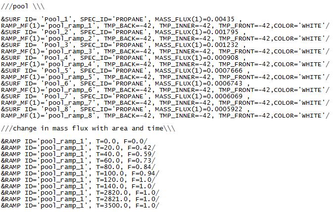
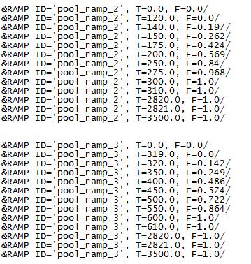
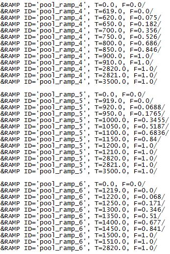
10 7 Table 1 Parameters defining the leak Parameter Mass flow rate Total mass of propane released Value 4.78 kg/s kg Fraction of propane flashed, F v Mass flow of propane flashed Mass flow of propane into pool kg/s 2.6 kg/s Using the mass flow rate of propane going into the pool i.e. 2.6 kg/s and the equations described in and 2.2.4, the pool spread and evaporation models were calculated. Based on the location of the release, dry medium sand was assumed as the ground (Appendix A). The pool evaporation rate is directly proportional to the surface area (radius) of the pool as is evident in Fig 2 and Fig 3. As time progresses, the change in evaporation rate gradually decreases as the surface cools. When the leak is contained after 2820s, the pool reaches a radius of 37.5 m. Fig 2. Increase in pool radius with time Fig 3. Increase in pool evaporation rate with time According to the data collected [1], an average wind speed of 3.6 m/s was reported blowing from the North South direction (Appendix C). The atmospheric stability was assumed to be class A due to the low wind speed, strong-moderate insolation and as the release was during the day. Wind Class is shown in Fig 4. The credibility of the wind data was initially questioned as the weathering station was located far from the area of the leak. After running
11 8 the FDS simulations we concluded that the wind data was inaccurate, further details of which have been included in Chapter 4. Fig 4. Wind Class 3.2 FDS Simulation Defining the Mesh All FDS computations are executed within a region made up of rectilinear volumes called meshes. Each mesh is divided into several rectangular cells which depend on the desired resolution of the flow dynamics [7]. The area of concern was determined to be 150m by 104m from the plot overview [1]. For our simulations, we assumed a mesh size of 200m*200m*10m with cell dimensions of 1m*1m. The following line is used to initialize the mesh. By default, FDS assumes that the exterior boundaries of the computational domain are solid walls [7]. For outdoor simulations, each boundary must be explicitly defined OPEN as shown below.
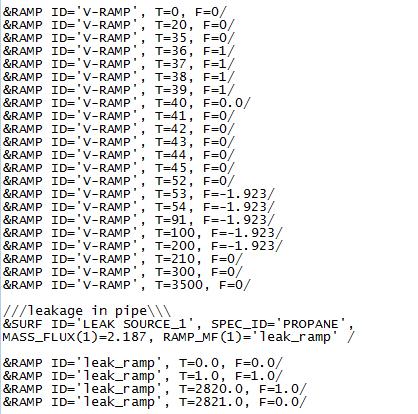
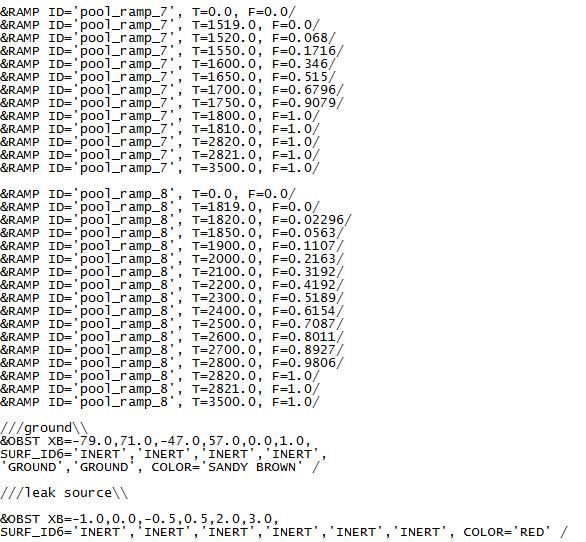
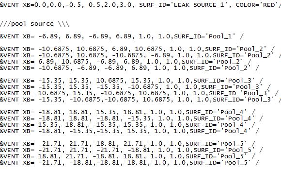
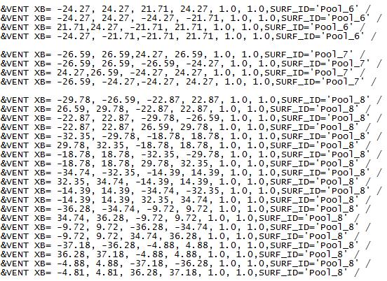
12 Specifying the Ambient Conditions and Wind Speed The release occurred on the 6 th of December 2013 in the Middle East, and hence an ambient condition of 20 C and 1 bar were assumed for the simulations. The MISC namelist is used to specify these conditions in FDS. There are a couple of methods available in FDS to specify a wind field, the one used in our simulations is the one recommended in the FDS user guide [7]. For this method, each component of the wind velocity vector is explicitly defined using U0, V0 and W0. Each velocity component can be individually varied with time and height. The following code, points a wind of 3.6 m/s in the negative x direction, i.e. from the right to the left of the mesh Defining the Sources of Propane Release There are two sources for the propane release into the atmosphere: propane flashing from the leak point and propane evaporating from the liquid pool on the ground. In FDS we have to specify separate models for both these sources. Defining a source of release in FDS is a three steps process: 1. Defining the leak in terms of the species released with SPEC namelist; the mass flux of the release etc. using the SURF namelist. 2. Include rectangular obstructions into the domain using OBST namelist. 3. Use VENT namelist to inject propane into the computational domain. The physical properties of propane gas are tabulated within FDS and need not be explicitly specified. An example of defining the source(s) is include below.
13 Gas Detectors and Obstructions There were 15 propane gas sensors located around the area of the release, Fig 5. The detectors were calibrated to alarm if the concentration of propane (vol %) increased above 25% of its Lower Flammable Limit (LFL) i.e. 2.1% (vol /vol). DEVC namelist is used to define the gas sensors in FDS. Each gas sensor has a time dependent output associated with it, which is stored in a comma-delimited ASCII file (.csv). At the end of the simulation, the.csv file was analyzed to note the time at which each sensor first reported a concentration greater than or equal to (Appendix C). Fig 5 Location of the gas detectors (not to scale) Any notable obstructions which might affect the flow path of propane vapors and the pool were included in the simulations using the OBST namelist.
 with the actual alarm summary included in Chapter 4.")
14 Smokeview Representation and Analysis For the base model of our project, we decided to exclude any wind as we didn t have accurate data. Further models with different wind profiles were developed to validate the model(s) with the actual alarm summary included in Chapter 4. All the data included in this Chapter are for the no wind condition. The dispersion path of the propane vapors can be visually represented by using the ISOF namelist. The concentrations (mol/mol) to be displayed in Smokeview must be explicitly specified. For our models, we selected concentrations of 2.1 % propane in the atmosphere, which is its LFL and 0.525% which is the concentration above which the detectors go off. Figure 6 shows the direction of the release from 14 secs to 452 secs. Fig 6 Spread of Propane Vapor As propane vapor is heavier than air, the height to which it is dispersed is limited. To determine the maximum height of the dispersed gas, we studied the propane concentrations at various planes and concluded that it is essentially zero above 9 m. Further analysis of the leak was done by examining the variation of propane volume fraction at different planes within the domain, using the SLCF namelist. Fig 7 shows the distribution of propane mole fraction, 10 minutes into the release, at the plane Z=1, which is the ground (sand) for our simulation.

15 12 Fig 7 Smokeview rendering of the propane fraction at Z=1 In the absence of any wind, the sequence in which the detectors alarm (i.e. reach a concentration above 25% LFL) is different from the detector alarm sequence collected from the release location as shown in Fig 8. Also, the total time required for all the detectors to sound is much greater as there is no external driving force to speed up the dispersion of propane vapors. Fig 8 Detector alarm summary
16 13 Table 2 Detector alarm summaries (No Wind) Actual Sequence Time between each FDS Sequence Time between each detector detector _A _A _B _A _B _B _A _B m/s from NE to SW For this case, we assumed a wind blowing at an average speed of 3.6 m/s from the NNE direction for the entire duration of the leak in accordance to the data provided (Appendix C). The North in the plot overview was in the negative x direction and hence the wind direction input into the FDS simulation was adjusted accordingly. Fig 9 depicts how the mole fraction of propane on the ground varied throughout the leak.

17 14 Fig 9 Variation of propane mole fraction on the ground (Case 1) A comparison of the detector alarm summaries in Fig 10, shows the inaccuracy of the wind data. Only five detectors marked in red reached a concentration above 25% LFL propane which is not consistent with the actual detector alarm summary. The unalarmed detectors were located opposite to the direction of the wind. Fig 10 Detector alarm summaries (Case 1)
18 15 Table 3 Detector alarm summaries (Case 1) Actual Sequence Time between each FDS Sequence Time between each detector detector Did not alarm Did not alarm Did not alarm Did not alarm 1734_A Did not alarm 1746_A _A Did not alarm 1734_B _A Did not alarm _B Did not alarm 1746_B Did not alarm _B Did not alarm CHAPTER 4 DISCUSSION AND CONCLUSIONS 4.1 Validation Studies FDS Validation Model Several simulations were carried out varying the wind speed and direction, and the following wind profile gave the most satisfactory results:
19 16 A strong gush of wind (3m/s) lasting for a very short duration of time (5 sec) blowing from south to north which may be attributed to the unstable atmospheric conditions of the region. A relatively benign but persistent wind of 0.5 m/s blowing from west to east. The following table summarizes the wind for this model. Table 4 Wind Profile (Case 2) Wind Profile No wind 35 s Duration 3 m/s South to North 5 s 0.5 m/s West to East 150 s Fig 11_A and 11_B show the effect of change in the wind speed and direction on the mole fraction of propane. Fig 11_A Variation of propane mole fraction on the ground (Case 2)

20 17 Fig 11_B Variation of propane mole fraction on the ground (Case 2) As shown in Table 5 and Fig 12, the detector alarm summary of our model closely resembled the actual sequence. Baring detector 2609, all the others were in sequence and the time differences between activation of each detector were also accurate, within a few seconds of the actual scenario. Table 5 Detector alarm summaries (Case 2) Actual Time between FDS Time between Difference between Case 2 Sequence each detector Sequence each detector and actual sequence (sec) _A A _A A _B B 1 0
21 _B B Fig 12 detector alarm summaries (case 2) Iterative Nature of FDS FDS and CFD modelling is an exercise in iteration. We started with a simplistic model and gradually increased the complexity of our models to match what happened at the release. Table 6 provides a summary of some of our model iterations. Table 6 Iterations in FDS modelling Model no Description 1-9 Simple models incorporating flashing and pool evaporation separately (indoor simulation) Introduction of wind into the system Increasing complexity of models to represent the leak in the absence of wind (indoor + outdoor simulation).
22 19 18 Model for a no wind condition Models trying to fit the given wind profile with simulation data. 39 Model verifying the inaccuracy of the wind data Predictive models to determine the wind data representative of the location. 65 Validated model representing the leak for the first 200 seconds. 4.2 Conclusion FDS was effectively used to model the propane release from the metering skid which helped in understanding the direction of the release, the cloud width and dispersion and variation of propane volume fraction with time and space. Despite the inaccuracy of the wind data, our final model could predict the actual path of the release for the first 200 secs (Fig 13) by assuming a wind profile which was representative of the region where the leak occurred (Section 4.1.1). Thus, we can conclude that our model can be effectively used in the prediction of similar release scenarios and as a tool for Root Cause Analysis.

23 20 Fig 13 Propane cloud dispersion during the first 200s of the leak CHAPTER 5 PROPOSED STEPS FORWARD 5.1 Improvement of results More demanding and complex equations to calculate the source terms to be entered into FDS that takes into account variables such as the actual size of the release, reduction in discharge pressure, etc. Add internal models to FDS to represent the vapor-liquid thermodynamics of flashing, pool spreading and evaporation. Use varying wind profiles across a year to form a coverage map.
24 In General Utilize CFD modelling to understand such releases in terms of the direction of release, vapor cloud width and dispersion etc. Use the results obtained from the models to assess risk mitigation steps for new developments and for Root Cause Analysis of incidents. Compare results with those from other CFD software. Collection of on-site wind data for sound release & dispersion analysis during risk management modeling, since CFD models are very sensitive to the wind profile.
25 22 References: [1] Confidential Data. Kenexis, May 2017 [2] McGrattan K., Hostikka S., McDermott R., Floyd J., Weinschenk C., Overholt K.. Fire Dynamics Simulator Technical Reference Guide 6 th Edition, Volume 1. NIST Special Publication , 2017 [3] Glenn P. Forney. Smokeview, A Tool for Visualizing Fire Dynamics Simulation Data, Volume 1. NIST Special Publication , 2017 [4] Center of Chemical Process Safety of the American Institute of Chemical Engineers. Guidelines for Chemical Process Quantitative Risk Analysis, 2 nd Edition. Wiley Interscience Publication, 2000 [5] Daniel A. Crowl, Joseph F. Louvar. Chemical Process Safety Fundamentals with Applications, 3 rd Edition. Prentice Hall Publication 2011 [6] Andrew Joseph Kohout. Evaluation of Fire Dynamics Simulator for Liquefied Natural Gas Vapor Dispersion Hazards. University of Maryland, College Park 2011 [7] McGrattan K., Hostikka S., McDermott R., Floyd J., Weinschenk C., Overholt K.. Fire Dynamics Simulator User s Guide 6 th Edition. NIST Special Publication 1019, 2017
26 23 APPENDIX A PHYSICAL PROPERTIES AND PLANT PLOT Table 1 Propane properties Parameter Value Unit Liquid density 580 kg/m 3 Initial liquid temp 311 K Boiling temp 231 K Heat of Vaporization, h fg 429 KJ/kg Heat capacity 2.45 KJ/kgK Table 2 Sand properties Parameter Value Unit Thermal conductivity 0.27 W/mK Thermal diffusivity m 2 /s Temperature 293 K Specific heat 0.8 KJ/kgK

27 24 APPENDIX B INPUT FILE FOR CASE 2
28 25
29 26
30 27

31 28

32 29
33 30 APPENDIX C Pool Vaporization: The total vapor loading into the atmosphere is due to the combined effect of flash evaporation and vaporization from the liquid pool formed on the ground which is governed by the equation [3]: dt mc p = H Lm (1) dt For a highly volatile liquid such as propane at steady state, heat transfer by conduction controls the vaporization rate. H, as the total heat flux in equation (1), can be simplified as heat transfer from the ground. The above equation can be simplified as [3]: m = H L (2) Simulating the increase in pool radius with time in FDS and Smokeview


34 31 Wind rose Csv output file of case 2


35 32 Computational domain in Smokeview Maximum height of the propane vapors at the release source
FIRE SAFETY DESIGN USING LARGE EDDY SIMULATION MODELS: EME BUILDING OF BUET: A CASE STUDY
 Proceedings of the International Conference on Mechanical Engineering 2011 (ICME2011) 18-20 December 2011, Dhaka, Bangladesh ICME11- FIRE SAFETY DESIGN USING LARGE EDDY SIMULATION MODELS: EME BUILDING
Evaporation Velocity of Cryogenic Liquid With and Without Spreading
 PetroChemistry 2016 Evaporation Velocity of Cryogenic Liquid With and Without Spreading 2016. 12. 06 Myungbae Kim Korea Institute of Machinery & Materials Contents Introduction Evaporation Model Experimental
Ammonia World New and Old 2017 conference. CFD Simulation of Ammonia Dispersion from a Vapor Box: Secondary Containment for Handling Ammonia Spills
 Ammonia World New and Old 2017 conference CFD Simulation of Ammonia Dispersion from a Vapor Box: Secondary Containment for Handling Ammonia Spills Alina Larin, Anat Tzur, Sigalit Shahar and Alexander Cohen
Modelling flammable chemical major hazards using the DRIFT 3 dispersion model
 Modelling flammable chemical major hazards using the DRIFT 3 dispersion model Zoe Chaplin a*, Helen Cruse a, Graham Tickle b, Harvey Tucker c a Health and Safety Executive, Harpur Hill, Buxton, Derbyshire
INDEX. (The index refers to the continuous pagination)
") (The index refers to the continuous pagination) Accuracy in physical models methods for assessing overall assessment acquisition of information acrylonitrile hazards polymerisation toxic effects toxic
(The index refers to the continuous pagination) Accuracy in physical models methods for assessing overall assessment acquisition of information acrylonitrile hazards polymerisation toxic effects toxic
Consequence Modeling Using the Fire Dynamics Simulator
 Consequence Modeling Using the Fire Dynamics Simulator Noah L. Ryder 1, 2 Jason A. Sutula, P.E. Christopher F. Schemel 2 Andrew J. Hamer Vincent Van Brunt, Ph.D., P.E. Abstract The use of Computational
MATH 1050Q Mathematical Modeling in the Environment
 MATH 1050Q Mathematical Modeling in the Environment Lecture 18. Basic Physics and Chemistry. Dmitriy Leykekhman Spring 2010 D. Leykekhman - MATH 1050Q Mathematical Modeling in the Environment Course info
A Zone Model for Fast Verification of Release of Ultrafine Water Mist for Fire Extinction in Compartments
 25 th ICDERS August 2 7, 2015 Leeds, UK A Zone Model for Fast Verification of Release of Ultrafine Water Mist for Fire Extinction in Compartments Francesco Saverio Marra Istituto di Ricerche sulla Combustione
PART 7 - TOPIC 2 CONSEQUENCE MODELING USING ALOHA
 PART 7 - TOPIC 2 CONSEQUENCE MODELING USING ALOHA Dr. Arshad Ahmad Email: arshad@utm.my 1 Software Commonly used for Risk Analysis Software SAFETI SFU CAFTAN ETRA HAZSEC. HAZTRAC. PHAST. WHAZAN EFFECTS.
ALOHA Decision Keys. Areal Locations of Hazardous Atmospheres. Mary Evans
 ALOHA Decision Keys Areal Locations of Hazardous Atmospheres Mary Evans Modeling and Simulation Studies Branch Hazardous Materials Response and Assessment Division Office of Ocean Resources Conservation
FLOW MEASUREMENT IN PIPES EXPERIMENT
 University of Leicester Engineering Department FLOW MEASUREMENT IN PIPES EXPERIMENT Page 1 FORMAL LABORATORY REPORT Name of the experiment: FLOW MEASUREMENT IN PIPES Author: Apollin nana chaazou Partner
IMPACT OF LES TURBULENCE SUBGRID MODELS IN THE JET RELEASE SIMULATION
 IMPACT OF LES TURBULENCE SUBGRID MODELS IN THE JET RELEASE SIMULATION E. S. FERREIRA JÚNIOR 1, S. S. V. VIANNA 1 1 State University of Campinas, Faculty of Chemical Engineering E-mail: elmo@feq.unicamp.br,
Hydrogen Vehicle Leak Modelling in Indoor Ventilated Environments.
 Excerpt from the Proceedings of the COMSOL Conference 2009 Milan Hydrogen Vehicle Leak Modelling in Indoor Ventilated Environments. A. Hallgarth *1, A. Zayer 1, A. Gatward 2 and J. Davies 2 1 Hazard Research
 WORKBOOK FOR CHEMICAL REACTOR RELIEF SYSTEM SIZING ANNEX 10 NOMENCLATURE A cross-sectional flow area of relief system (m 2 ) A actual actual cross-sectional area of safety valve nozzle (m 2 ) A approx
Mass flow determination in flashing openings
 Int. Jnl. of Multiphysics Volume 3 Number 4 009 40 Mass flow determination in flashing openings Geanette Polanco Universidad Simón Bolívar Arne Holdø Narvik University College George Munday Coventry University
Journal of Industrial Engineering Research. Spreadsheet Modelling for Temperature Profile inside Palm Oil Fresh Fruit Bunch
 IWNEST PUBLISHER Journal of Industrial Engineering Research (ISSN: 2077-4559) Journal home page: http://www.iwnest.com/aace/ Spreadsheet Modelling for Temperature Profile inside Palm Oil Fresh Fruit Bunch
Documentation of the Solutions to the SFPE Heat Transfer Verification Cases
 Documentation of the Solutions to the SFPE Heat Transfer Verification Cases Prepared by a Task Group of the SFPE Standards Making Committee on Predicting the Thermal Performance of Fire Resistive Assemblies
Lesson 6 Review of fundamentals: Fluid flow
 Lesson 6 Review of fundamentals: Fluid flow The specific objective of this lesson is to conduct a brief review of the fundamentals of fluid flow and present: A general equation for conservation of mass
Consequence modeling using the fire dynamics simulator
 Journal of Hazardous Materials 115 (2004) 149 154 Consequence modeling using the fire dynamics simulator Noah L. Ryder, Jason A. Sutula, Christopher F. Schemel, Andrew J. Hamer, Vincent Van Brunt Packer
Keywords: Hazardous Material Transportation, Consequence Analysis, CFD models, Heavy Gas Dispersion Modeling, LPG, Viareggio accident.
 Safety of LPG rail transportation: influence of safety barriers V. Busini*, M. Derudi, R. Rota Politecnico di Milano, Department of Chemistry, Materials and Chemical Engineering G. Natta, Piazza Leonardo
LEAKLESS COOLING SYSTEM V.2 PRESSURE DROP CALCULATIONS AND ASSUMPTIONS
 CH-1211 Geneva 23 Switzerland EDMS No. ST/CV - Cooling of Electronics & Detectors GUIDE LEAKLESS COOLING SYSTEM V.2 PRESSURE DROP CALCULATIONS AND ASSUMPTIONS Objectives Guide to Leakless Cooling System
Using Dow Chemical Index to Review Emergency Procedure at Laboratory
 Using Dow Chemical Index to Review Emergency Procedure at Laboratory Present for 2 nd ASCEL in Laboratory Depok, 1-2 December 2015 B 027 BACKGROUND The laboratory environment can be a hazardous place to
CHAPTER 5 MASS AND ENERGY ANALYSIS OF CONTROL VOLUMES
 Thermodynamics: An Engineering Approach 8th Edition in SI Units Yunus A. Çengel, Michael A. Boles McGraw-Hill, 2015 CHAPTER 5 MASS AND ENERGY ANALYSIS OF CONTROL VOLUMES Lecture slides by Dr. Fawzi Elfghi
Quantifying Thermophoretic Deposition of Soot on Surfaces
 Quantifying Thermophoretic Deposition of Soot on Surfaces Amy Mensch, Thomas Cleary National Institute of Standards and Technology, Gaithersburg, MD, USA Abstract Quantitative data on deposition of soot
REDUCING COMPUTATIONAL TIME IN TURBULENT JET MODELLING FOR GAS DISPERSION SIMULATION
 REDUCING COMPUTATIONAL TIME IN TURBULENT JET MODELLING FOR GAS DISPERSION SIMULATION E. S. FERREIRA Jr 1, T. FERREIRA 1 and S.S.V. VIANNA 1 1 University of Campinas (Unicamp), School of Chemical Engineering
Fluid Dynamics Exercises and questions for the course
 Fluid Dynamics Exercises and questions for the course January 15, 2014 A two dimensional flow field characterised by the following velocity components in polar coordinates is called a free vortex: u r
Study Folder: RDS San Benedetto PHAST 6.5. SHELL - Johnson Material. METHANE Ambient Temperature Ambient Relative Humidity
 JET FIRE REPORT Unique Audit Nuber: 2.996 Study 14" 8 bar Horizontal Base Case Data Weather: Speed: 2, Study\Category 2/F /s Stability: F \\Study\14" 8 bar Horizontal Flae Data User-Defined Quantities
Pipe Flow. Lecture 17
 Pipe Flow Lecture 7 Pipe Flow and the Energy Equation For pipe flow, the Bernoulli equation alone is not sufficient. Friction loss along the pipe, and momentum loss through diameter changes and corners
MATH 1050QC Mathematical Modeling in the Environment
 MATH 1050QC Mathematical Modeling in the Environment Lecture 20. Characterization of Toxicity Hazards. Chemical Principles. Dmitriy Leykekhman Spring 2009 D. Leykekhman - MATH 1050QC Mathematical Modeling
Ben Wolfe 11/3/14. Figure 1: Theoretical diagram showing the each step of heat loss.
 Condenser Analysis Water Cooled Model: For this condenser design there will be a coil of stainless steel tubing suspended in a bath of cold water. The cold water will be stationary and begin at an ambient
CFD modeling of water spray interaction with dense gas clouds
 CFD modeling of water spray interaction with dense gas clouds Robert N. Meroney a, a Wind Engineering Software, Fort Collins, CO,USA, Robert.Meroney@ColoState.Edu 1 INTRODUCTION Water spray curtains can
Lab Section Date. ME4751 Air Flow Rate Measurement
 Name Lab Section Date ME4751 Air Flow Rate Measurement Objective The objective of this experiment is to determine the volumetric flow rate of air flowing through a pipe using a Pitot-static tube and a
DEVELOPMENT OF A COMPRESSED CARBON DIOXIDE PROPULSION UNIT FOR NEAR-TERM MARS SURFACE APPLICATIONS
 DEVELOPMENT OF A COMPRESSED CARBON DIOXIDE PROPULSION UNIT FOR NEAR-TERM MARS SURFACE APPLICATIONS Erin Blass Old Dominion University Advisor: Dr. Robert Ash Abstract This work has focused on the development
ME332 FLUID MECHANICS LABORATORY (PART I)
") ME332 FLUID MECHANICS LABORATORY (PART I) Mihir Sen Department of Aerospace and Mechanical Engineering University of Notre Dame Notre Dame, IN 46556 Version: January 14, 2002 Contents Unit 1: Hydrostatics
ME332 FLUID MECHANICS LABORATORY (PART I) Mihir Sen Department of Aerospace and Mechanical Engineering University of Notre Dame Notre Dame, IN 46556 Version: January 14, 2002 Contents Unit 1: Hydrostatics
THE HYDRAULIC PERFORMANCE OF ORIENTED SPUR DIKE IMPLEMENTATION IN OPEN CHANNEL
 Tenth International Water Technology Conference, IWTC10 2006, Alexandria, Egypt 281 THE HYDRAULIC PERFORMANCE OF ORIENTED SPUR DIKE IMPLEMENTATION IN OPEN CHANNEL Karima Attia 1 and Gamal El Saied 2 1
Modeling of dispersed phase by Lagrangian approach in Fluent
 Lappeenranta University of Technology From the SelectedWorks of Kari Myöhänen 2008 Modeling of dispersed phase by Lagrangian approach in Fluent Kari Myöhänen Available at: https://works.bepress.com/kari_myohanen/5/
DEVELOPED LAMINAR FLOW IN PIPE USING COMPUTATIONAL FLUID DYNAMICS M.
 DEVELOPED LAMINAR FLOW IN PIPE USING COMPUTATIONAL FLUID DYNAMICS M. Sahu 1, Kishanjit Kumar Khatua and Kanhu Charan Patra 3, T. Naik 4 1, &3 Department of Civil Engineering, National Institute of technology,
EXPERIMENT No.1 FLOW MEASUREMENT BY ORIFICEMETER
 EXPERIMENT No.1 FLOW MEASUREMENT BY ORIFICEMETER 1.1 AIM: To determine the co-efficient of discharge of the orifice meter 1.2 EQUIPMENTS REQUIRED: Orifice meter test rig, Stopwatch 1.3 PREPARATION 1.3.1
Open Channel Flow I - The Manning Equation and Uniform Flow COURSE CONTENT
 Open Channel Flow I - The Manning Equation and Uniform Flow Harlan H. Bengtson, PhD, P.E. COURSE CONTENT 1. Introduction Flow of a liquid may take place either as open channel flow or pressure flow. Pressure
Influence of material of boundary condition on temperature and visibility
 Influence of material of boundary condition on temperature and visibility Luciano Nigro, Andrea Ferrari, Elisabetta Filippo H.A.E Srl Jensen Hughes EU Alliance Via Vincenzo Monti, 52 Rho (Mi), ITALY Executive
Prediction of Performance Characteristics of Orifice Plate Assembly for Non-Standard Conditions Using CFD
 International Journal of Engineering and Technical Research (IJETR) ISSN: 2321-0869, Volume-3, Issue-5, May 2015 Prediction of Performance Characteristics of Orifice Plate Assembly for Non-Standard Conditions
CHAM Case Study CFD Modelling of Gas Dispersion from a Ruptured Supercritical CO 2 Pipeline
 CHAM Limited Pioneering CFD Software for Education & Industry CHAM Case Study CFD Modelling of Gas Dispersion from a Ruptured Supercritical CO 2 Pipeline 1. INTRODUCTION This demonstration calculation
1. INTRODUCTION TO CFD SPRING 2018
 1. INTRODUCTION TO CFD SPRING 018 1.1 What is computational fluid dynamics? 1. Basic principles of CFD 1.3 Stages in a CFD simulation 1.4 Fluid-flow equations 1.5 The main discretisation methods Appendices
Financial concerns Regulatory developments Superfund, Resource Conservation and Recovery Act (RCRA) frame Industry Reactions
 frame Industry Reactions") Hazardous Materials Management Background Episodic Events: 1979 - Three Mile Island - Harrisburg, Pennsylvania Partial meltdown of radioactive core Lessons Technological systems can fail in unexpected
Hazardous Materials Management Background Episodic Events: 1979 - Three Mile Island - Harrisburg, Pennsylvania Partial meltdown of radioactive core Lessons Technological systems can fail in unexpected
MAE 598 Project #1 Jeremiah Dwight
 MAE 598 Project #1 Jeremiah Dwight OVERVIEW A simple hot water tank, illustrated in Figures 1 through 3 below, consists of a main cylindrical tank and two small side pipes for the inlet and outlet. All
1. INTRODUCTION TO CFD SPRING 2019
 1. INTRODUCTION TO CFD SPRING 2019 1.1 What is computational fluid dynamics? 1.2 Basic principles of CFD 1.3 Stages in a CFD simulation 1.4 Fluid-flow equations 1.5 The main discretisation methods Appendices
An Essential Requirement in CV Based Industrial Appliances.
 Measurement of Flow P M V Subbarao Professor Mechanical Engineering Department An Essential Requirement in CV Based Industrial Appliances. Mathematics of Flow Rate The Scalar Product of two vectors, namely
Isentropic Efficiency in Engineering Thermodynamics
 June 21, 2010 Isentropic Efficiency in Engineering Thermodynamics Introduction This article is a summary of selected parts of chapters 4, 5 and 6 in the textbook by Moran and Shapiro (2008. The intent
9. Pumps (compressors & turbines) Partly based on Chapter 10 of the De Nevers textbook.
 Partly based on Chapter 10 of the De Nevers textbook.") Lecture Notes CHE 31 Fluid Mechanics (Fall 010) 9. Pumps (compressors & turbines) Partly based on Chapter 10 of the De Nevers textbook. Basics (pressure head, efficiency, working point, stability) Pumps
Lecture Notes CHE 31 Fluid Mechanics (Fall 010) 9. Pumps (compressors & turbines) Partly based on Chapter 10 of the De Nevers textbook. Basics (pressure head, efficiency, working point, stability) Pumps
Chapter 4 DYNAMICS OF FLUID FLOW
 Faculty Of Engineering at Shobra nd Year Civil - 016 Chapter 4 DYNAMICS OF FLUID FLOW 4-1 Types of Energy 4- Euler s Equation 4-3 Bernoulli s Equation 4-4 Total Energy Line (TEL) and Hydraulic Grade Line
Orifice and Venturi Pipe Flow Meters
 Orifice and Venturi Pipe Flow Meters by Harlan H. Bengtson, PhD, P.E. 1. Introduction Your Course Title Here The flow rate of a fluid flowing in a pipe under pressure is measured for a variety of applications,
data Subsonic, helium release H 2 release concentrations Choked, Steady-state, concentrations release Transient, Subsonic, concentrations Subsonic,
 GRAD CFD Software Validation The Gas Release And Dispersion (GRAD) CFD modeling tool has been designed as a customized module based on the commercial general-purpose CFD software, PHOENICS [1]. GRAD CFD
Fire Engineering Principles Workbook
 F Fire Engineering Principles Workbook R C The aim of this course is to enable the student to understand fundamental Fire Engineering Principles. It will give you the basic principles and underlying principles
Level 7 Post Graduate Diploma in Engineering Heat and mass transfer
 9210-221 Level 7 Post Graduate Diploma in Engineering Heat and mass transfer 0 You should have the following for this examination one answer book non programmable calculator pen, pencil, drawing instruments
Fluid Mechanics Prof. S.K. Som Department of Mechanical Engineering Indian Institute of Technology, Kharagpur
 Fluid Mechanics Prof. S.K. Som Department of Mechanical Engineering Indian Institute of Technology, Kharagpur Lecture - 42 Flows with a Free Surface Part II Good morning. I welcome you to this session
10.52 Mechanics of Fluids Spring 2006 Problem Set 3
 10.52 Mechanics of Fluids Spring 2006 Problem Set 3 Problem 1 Mass transfer studies involving the transport of a solute from a gas to a liquid often involve the use of a laminar jet of liquid. The situation
LECTURE 6- ENERGY LOSSES IN HYDRAULIC SYSTEMS SELF EVALUATION QUESTIONS AND ANSWERS
 LECTURE 6- ENERGY LOSSES IN HYDRAULIC SYSTEMS SELF EVALUATION QUESTIONS AND ANSWERS 1. What is the head loss ( in units of bars) across a 30mm wide open gate valve when oil ( SG=0.9) flow through at a
CHME 302 CHEMICAL ENGINEERING LABOATORY-I EXPERIMENT 302-V FREE AND FORCED CONVECTION
 CHME 302 CHEMICAL ENGINEERING LABOATORY-I EXPERIMENT 302-V FREE AND FORCED CONVECTION OBJECTIVE The objective of the experiment is to compare the heat transfer characteristics of free and forced convection.
NUMERICAL INVESTIGATION ON THE EFFECT OF COOLING WATER SPRAY ON HOT SUPERSONIC JET
 Volume 119 No. 12 2018, 59-63 ISSN: 1314-3395 (on-line version) url: http://www.ijpam.eu ijpam.eu NUMERICAL INVESTIGATION ON THE EFFECT OF COOLING WATER SPRAY ON HOT SUPERSONIC JET Ramprasad T and Jayakumar
Multiphase Flow and Heat Transfer
 Multiphase Flow and Heat Transfer ME546 -Sudheer Siddapureddy sudheer@iitp.ac.in Two Phase Flow Reference: S. Mostafa Ghiaasiaan, Two-Phase Flow, Boiling and Condensation, Cambridge University Press. http://dx.doi.org/10.1017/cbo9780511619410
Rate of Flow Quantity of fluid passing through any section (area) per unit time
 per unit time") Kinematics of Fluid Flow Kinematics is the science which deals with study of motion of liquids without considering the forces causing the motion. Rate of Flow Quantity of fluid passing through any section
Kinematics of Fluid Flow Kinematics is the science which deals with study of motion of liquids without considering the forces causing the motion. Rate of Flow Quantity of fluid passing through any section
Chapter 5. Mass and Energy Analysis of Control Volumes. by Asst. Prof. Dr.Woranee Paengjuntuek and Asst. Prof. Dr.Worarattana Pattaraprakorn
 Chapter 5 Mass and Energy Analysis of Control Volumes by Asst. Prof. Dr.Woranee Paengjuntuek and Asst. Prof. Dr.Worarattana Pattaraprakorn Reference: Cengel, Yunus A. and Michael A. Boles, Thermodynamics:
10 minutes reading time is allowed for this paper.
 EGT1 ENGINEERING TRIPOS PART IB Tuesday 31 May 2016 2 to 4 Paper 4 THERMOFLUID MECHANICS Answer not more than four questions. Answer not more than two questions from each section. All questions carry the
2 nd Joint Summer School on Fuel Cell and Hydrogen Technology September 2012, Crete, Greece. Hydrogen fires
 2 nd Joint Summer School on Fuel Cell and Hydrogen Technology 17 28 September 2012, Crete, Greece Hydrogen fires Sile Brennan (on behalf of the HySAFER group) Hydrogen Safety Engineering and Research Centre
Special Topics, Future Development and Case Practice
 Special Topics, Future Development and Case Practice 2009_2nd semester En Sup Yoon Special Topics Domino effects Predict the occurrence of such incidents that affect nearby items by thermal, blast or fragment
Study on Train Obstruction Effect on Smoke Control near Tunnel Cross-Passage
 Study on Train Obstruction Effect on Smoke Control near Tunnel Cross-Passage Hou Y. S., Li Y. F.*, Li J. M. Beijing University of Technology, College of Architecture and Civil Engineering, Beijing, China
IX. COMPRESSIBLE FLOW. ρ = P
 IX. COMPRESSIBLE FLOW Compressible flow is the study of fluids flowing at speeds comparable to the local speed of sound. This occurs when fluid speeds are about 30% or more of the local acoustic velocity.
Simulation of unsteady muzzle flow of a small-caliber gun
 Advances in Fluid Mechanics VI 165 Simulation of unsteady muzzle flow of a small-caliber gun Y. Dayan & D. Touati Department of Computational Mechanics & Ballistics, IMI, Ammunition Group, Israel Abstract
2 Internal Fluid Flow
 Internal Fluid Flow.1 Definitions Fluid Dynamics The study of fluids in motion. Static Pressure The pressure at a given point exerted by the static head of the fluid present directly above that point.
ESCI 485 Air/Sea Interaction Lesson 1 Stresses and Fluxes Dr. DeCaria
 ESCI 485 Air/Sea Interaction Lesson 1 Stresses and Fluxes Dr DeCaria References: An Introduction to Dynamic Meteorology, Holton MOMENTUM EQUATIONS The momentum equations governing the ocean or atmosphere
TankExampleNov2016. Table of contents. Layout
 Table of contents Task... 2 Calculation of heat loss of storage tanks... 3 Properties ambient air Properties of air... 7 Heat transfer outside, roof Heat transfer in flow past a plane wall... 8 Properties
C C C C 2 C 2 C 2 C + u + v + (w + w P ) = D t x y z X. (1a) y 2 + D Z. z 2
 = D t x y z X. (1a) y 2 + D Z. z 2") This chapter provides an introduction to the transport of particles that are either more dense (e.g. mineral sediment) or less dense (e.g. bubbles) than the fluid. A method of estimating the settling velocity
This chapter provides an introduction to the transport of particles that are either more dense (e.g. mineral sediment) or less dense (e.g. bubbles) than the fluid. A method of estimating the settling velocity
Fluid Mechanics Prof. T.I. Eldho Department of Civil Engineering Indian Institute of Technology, Bombay. Lecture - 17 Laminar and Turbulent flows
 Fluid Mechanics Prof. T.I. Eldho Department of Civil Engineering Indian Institute of Technology, Bombay Lecture - 17 Laminar and Turbulent flows Welcome back to the video course on fluid mechanics. In
EXPERIMENT NO. 4 CALIBRATION OF AN ORIFICE PLATE FLOWMETER MECHANICAL ENGINEERING DEPARTMENT KING SAUD UNIVERSITY RIYADH
 EXPERIMENT NO. 4 CALIBRATION OF AN ORIFICE PLATE FLOWMETER MECHANICAL ENGINEERING DEPARTMENT KING SAUD UNIVERSITY RIYADH Submitted By: ABDULLAH IBN ABDULRAHMAN ID: 13456789 GROUP A EXPERIMENT PERFORMED
Principles of Convection
 Principles of Convection Point Conduction & convection are similar both require the presence of a material medium. But convection requires the presence of fluid motion. Heat transfer through the: Solid
MODELING OF THE CRYOGENIC LIQUID POOL EVAPORATION AND THE EFFECT OF THE CONVECTIVE HEAT TRANSFER FROM ATMOSPHERE. A Thesis WAQAS NAWAZ
 MODELING OF THE CRYOGENIC LIQUID POOL EVAPORATION AND THE EFFECT OF THE CONVECTIVE HEAT TRANSFER FROM ATMOSPHERE A Thesis by WAQAS NAWAZ Submitted to the Office of Graduate and Professional Studies of
Experiment- To determine the coefficient of impact for vanes. Experiment To determine the coefficient of discharge of an orifice meter.
 SUBJECT: FLUID MECHANICS VIVA QUESTIONS (M.E 4 th SEM) Experiment- To determine the coefficient of impact for vanes. Q1. Explain impulse momentum principal. Ans1. Momentum equation is based on Newton s
SEM-2017(03HI MECHANICAL ENGINEERING. Paper II. Please read each of the following instructions carefully before attempting questions.
 We RoU No. 700095 Candidate should write his/her Roll No. here. Total No. of Questions : 7 No. of Printed Pages : 7 SEM-2017(03HI MECHANICAL ENGINEERING Paper II Time ; 3 Hours ] [ Total Marks : 0 Instructions
FLOW FRICTION CHARACTERISTICS OF CONCRETE PRESSURE PIPE
 11 ACPPA TECHNICAL SERIES FLOW FRICTION CHARACTERISTICS OF CONCRETE PRESSURE PIPE This paper presents formulas to assist in hydraulic design of concrete pressure pipe. There are many formulas to calculate
Fluid Dynamics Midterm Exam #2 November 10, 2008, 7:00-8:40 pm in CE 110
 CVEN 311-501 Fluid Dynamics Midterm Exam #2 November 10, 2008, 7:00-8:40 pm in CE 110 Name: UIN: Instructions: Fill in your name and UIN in the space above. There should be 11 pages including this one.
Convective Mass Transfer
 Convective Mass Transfer Definition of convective mass transfer: The transport of material between a boundary surface and a moving fluid or between two immiscible moving fluids separated by a mobile interface
Introduction to Heat and Mass Transfer. Week 12
 Introduction to Heat and Mass Transfer Week 12 Next Topic Convective Heat Transfer» Heat and Mass Transfer Analogy» Evaporative Cooling» Types of Flows Heat and Mass Transfer Analogy Equations governing
150A Review Session 2/13/2014 Fluid Statics. Pressure acts in all directions, normal to the surrounding surfaces
 Fluid Statics Pressure acts in all directions, normal to the surrounding surfaces or Whenever a pressure difference is the driving force, use gauge pressure o Bernoulli equation o Momentum balance with
Chapter 5. Mass and Energy Analysis of Control Volumes
 Chapter 5 Mass and Energy Analysis of Control Volumes Conservation Principles for Control volumes The conservation of mass and the conservation of energy principles for open systems (or control volumes)
Diffusional Growth of Liquid Phase Hydrometeros.
 Diffusional Growth of Liquid Phase Hydrometeros. I. Diffusional Growth of Liquid Phase Hydrometeors A. Basic concepts of diffusional growth. 1. To understand the diffusional growth of a droplet, we must
Experimental and Numerical Investigation of Two- Phase Flow through Enlarging Singularity
 Purdue University Purdue e-pubs International Refrigeration and Air Conditioning Conference School of Mechanical Engineering 212 Experimental and Numerical Investigation of Two- Phase Flow through Enlarging
Applied Fluid Mechanics
 Applied Fluid Mechanics 1. The Nature of Fluid and the Study of Fluid Mechanics 2. Viscosity of Fluid 3. Pressure Measurement 4. Forces Due to Static Fluid 5. Buoyancy and Stability 6. Flow of Fluid and
Biological Process Engineering An Analogical Approach to Fluid Flow, Heat Transfer, and Mass Transfer Applied to Biological Systems
 Biological Process Engineering An Analogical Approach to Fluid Flow, Heat Transfer, and Mass Transfer Applied to Biological Systems Arthur T. Johnson, PhD, PE Biological Resources Engineering Department
Heat Transfer Convection
 Heat ransfer Convection Previous lectures conduction: heat transfer without fluid motion oday (textbook nearly 00 pages) Convection: heat transfer with fluid motion Research methods different Natural Convection
CE Final Exam. December 12, Name. Student I.D.
 CE 100 - December 12, 2009 Name Student I.D. This exam is closed book. You are allowed three sheets of paper (8.5 x 11, both sides) of your own notes. You will be given three hours to complete four problems.
Applied Fluid Mechanics
 Applied Fluid Mechanics 1. The Nature of Fluid and the Study of Fluid Mechanics 2. Viscosity of Fluid 3. Pressure Measurement 4. Forces Due to Static Fluid 5. Buoyancy and Stability 6. Flow of Fluid and
CFD MODELING OF ROAD TUNNEL FIRES
 CFD MODELING OF ROAD TUNNEL FIRES M. Derudi, S. Tavelli, A. Frassoldati, A. Cuoci marco.derudi@polimi.it Politecnico di Milano, Dip. di Chimica, Materiali e Ingegneria Chimica G. Natta / CIIRCO, Milano
INTRODUCTION TO FLUID MECHANICS June 27, 2013
 INTRODUCTION TO FLUID MECHANICS June 27, 2013 PROBLEM 3 (1 hour) A perfect liquid of constant density ρ and constant viscosity µ fills the space between two infinite parallel walls separated by a distance
first law of ThermodyNamics
 first law of ThermodyNamics First law of thermodynamics - Principle of conservation of energy - Energy can be neither created nor destroyed Basic statement When any closed system is taken through a cycle,
If there is convective heat transfer from outer surface to fluid maintained at T W.
 Heat Transfer 1. What are the different modes of heat transfer? Explain with examples. 2. State Fourier s Law of heat conduction? Write some of their applications. 3. State the effect of variation of temperature
405 Compact Orifice Series and 1595 Conditioning Orifice Plate Flow Test Data Book and Flow Handbook
 Reference Manual 405 Compact Orifice Series and 1595 Conditioning Orifice Plate Flow Test Book and Flow Handbook www.rosemount.com Reference Manual 405 and 1595 405 Compact Orifice Series and 1595 Conditioning
Compressible Gas Flow
 Compressible Gas Flow by Elizabeth Adolph Submitted to Dr. C. Grant Willson CHE53M Department of Chemical Engineering The University of Texas at Austin Fall 008 Compressible Gas Flow Abstract In this lab,
Atmospheric pressure. 9 ft. 6 ft
 Name CEE 4 Final Exam, Aut 00; Answer all questions; 145 points total. Some information that might be helpful is provided below. A Moody diagram is printed on the last page. For water at 0 o C (68 o F):
Department of Meteorology University of Nairobi. Laboratory Manual. Micrometeorology and Air pollution SMR 407. Prof. Nzioka John Muthama
 Department of Meteorology University of Nairobi Laboratory Manual Micrometeorology and Air pollution SMR 407 Prof. Nioka John Muthama Signature Date December 04 Version Lab : Introduction to the operations
Advanced Hydraulics Prof. Dr. Suresh A. Kartha Department of Civil Engineering Indian Institute of Technology, Guwahati
 Advanced Hydraulics Prof. Dr. Suresh A. Kartha Department of Civil Engineering Indian Institute of Technology, Guwahati Module - 2 Uniform Flow Lecture - 1 Introduction to Uniform Flow Good morning everyone,