Capacitors. C d. An electrical component which stores charge. parallel plate capacitor. Scale in cm
|
|
|
- Erik Cross
- 6 years ago
- Views:
Transcription


1 apaciors An elecrical componen which sores charge E 2 2 d A 2 parallel plae capacior Scale in cm
 in 745")
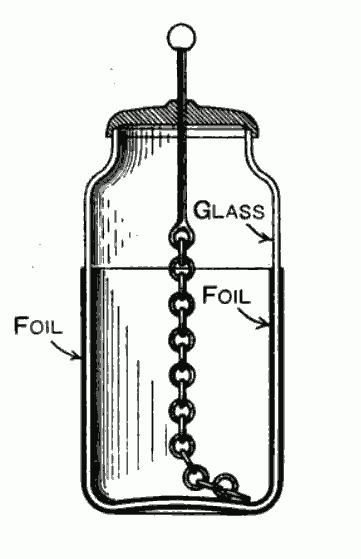
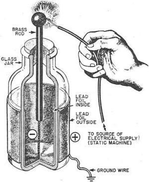
2 Leyden Jars I was invened independenly by German cleric Ewald Georg von Kleis on Ocober 745 and by Duch scienis Pieer van Musschenbroek of Leiden (Leyden) in
3

4 Parallel plae capacior


5 A dielecric increases he charge on he plaes d A

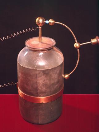
6 apaciance is measured in Farads -2 pf = F F means one coulomb per uni vol beween he capacior plaes. A Leyden Jar has a capaciance of around nf. A ypical circui board capacior will have capaciance from a few pf up o a large number of mf apaciors in a parallel configuraion each have he same applied volage. The oal charge sored is herefore 2... n Since he oal capaciance is given by /... 2 n Therefore parallel capaciances add


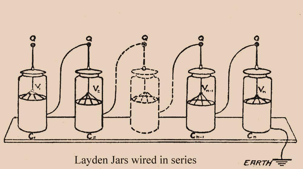
7 Sum of volage drops across capaciors mus equae o he applied volage 2... n n Hence: n n n n n Now he charge on each adjacen capacior plae mus be he same, oherwise curren would flow beween he capaciors, re-apporioning charge 2... n Hence:... 2 n Therefore he reciprocals of series capaciances add
8 apaciance examples 2 3?? ?? ? 2 2? 3 2
9 Energy sored in a capacior The insananeous power required o esablish volage across he plaes of a capacior is P I In ime inerval d, he amoun of charge added o he capacior is d d Hence curren I is P P I d d Toal energy required o esablish volage across he capacior plaes (in ime ) is herefore d E Pd d d 2 E d E 2 I d d d d E 2 2

10 The capaciance of a meal sphere of radius R is given by 4 R The permiiviy of free space is 8.85 Fm 2 - So he apaciance of a.2m radius an der Graaf generaor is abou 22pF The energy sored in a capacior is E 2 2 The volage of a ypical an der Graaf migh be as high as 3k Hence he energy discharged is only abou J and he charge abou 6.6m 2 Reference

 is he basis of")


11 apaciors, combined wih oher basic componens such as resisors and inducors can form a huge variey of circuis, each wih a differen applicaion. An inegraed circui (on a chip ) is he basis of modern elecronics. A compuer microprocessor may conain billions of circuis! This paricular circui generaes a sine wave oscillaing signal a a frequency dependen upon he parameers of he componens i.e. capaciance, inducance ec
12 harging a capacior using a D source. Swich closed. urren flows hrough resisor and posiive charge builds up on righ capacior plae. An equal amoun of negaive charge builds up on lef plae. 2. Elecrical field se up beween capacior plaes as no curren can flow. olage beween he plaes is = / where is he oal charge deposied and is he capaciance ( charge per uni vol ) Swich R 3. As charge builds up on righ plae, poenial difference beween capacior and source reduces. This reduces he curren flowing ono he plae. Evenually he volage becomes and hence no more curren can flow. 3. Noe he amoun of charge which can be deposied depends on he resuling elecrical field srengh beween he plaes. Above he breakdown field srengh, curren will flow beween he plaes Dielecric Air 3 x 6 Mineral oil 5 x 6 Neoprene 6 x 6 Waer 65 x 6 Breakdown field srengh /m - Mica 8 x 6
13 harging a capacior using a D source IR I capacior charge, volage relaionship Ohm s law d d Definiion of curren d I R d d d d R R ln ln ln R e R ln R e R R
14 Discharging a capacior d IR I d capacior charge, volage relaionship I R d d Ohm s law Noe = when = Definiion of curren, and negaive since charge is discharged from plaes R R R ln ln d e R d R e R So R is a characerisic ime for charging or discharging a capacior R
Capacitors & Inductors
 apaciors & Inducors EEE5 Elecric ircuis Anawach Sangswang Dep. of Elecrical Engineering KMUTT Elecric Field Elecric flux densiy Elecric field srengh E Elecric flux lines always exend from a posiively charged
Chapter 4 AC Network Analysis
 haper 4 A Nework Analysis Jaesung Jang apaciance Inducance and Inducion Time-Varying Signals Sinusoidal Signals Reference: David K. heng, Field and Wave Elecromagneics. Energy Sorage ircui Elemens Energy
Inductor Energy Storage
 School of Compuer Science and Elecrical Engineering 5/5/ nducor Energy Sorage Boh capaciors and inducors are energy sorage devices They do no dissipae energy like a resisor, bu sore and reurn i o he circui
dv 7. Voltage-current relationship can be obtained by integrating both sides of i = C :
 EECE202 NETWORK ANALYSIS I Dr. Charles J. Kim Class Noe 22: Capaciors, Inducors, and Op Amp Circuis A. Capaciors. A capacior is a passive elemen designed o sored energy in is elecric field. 2. A capacior
Chapter 16: Summary. Instructor: Jean-François MILLITHALER.
 Chaper 16: Summary Insrucor: Jean-François MILLITHALER hp://faculy.uml.edu/jeanfrancois_millihaler/funelec/spring2017 Slide 1 Curren & Charge Elecric curren is he ime rae of change of charge, measured
Phys1112: DC and RC circuits
 Name: Group Members: Dae: TA s Name: Phys1112: DC and RC circuis Objecives: 1. To undersand curren and volage characerisics of a DC RC discharging circui. 2. To undersand he effec of he RC ime consan.
EECE251. Circuit Analysis I. Set 4: Capacitors, Inductors, and First-Order Linear Circuits
 EEE25 ircui Analysis I Se 4: apaciors, Inducors, and Firs-Order inear ircuis Shahriar Mirabbasi Deparmen of Elecrical and ompuer Engineering Universiy of Briish olumbia shahriar@ece.ubc.ca Overview Passive
( ) = Q 0. ( ) R = R dq. ( t) = I t
 = Q 0. ( ) R = R dq. ( t) = I t") ircuis onceps The addiion of a simple capacior o a circui of resisors allows wo relaed phenomena o occur The observaion ha he ime-dependence of a complex waveform is alered by he circui is referred o as
ircuis onceps The addiion of a simple capacior o a circui of resisors allows wo relaed phenomena o occur The observaion ha he ime-dependence of a complex waveform is alered by he circui is referred o as
2.4 Cuk converter example
 2.4 Cuk converer example C 1 Cuk converer, wih ideal swich i 1 i v 1 2 1 2 C 2 v 2 Cuk converer: pracical realizaion using MOSFET and diode C 1 i 1 i v 1 2 Q 1 D 1 C 2 v 2 28 Analysis sraegy This converer
7. Capacitors and Inductors
 7. Capaciors and Inducors 7. The Capacior The ideal capacior is a passive elemen wih circui symbol The curren-volage relaion is i=c dv where v and i saisfy he convenions for a passive elemen The capacior
Reading from Young & Freedman: For this topic, read sections 25.4 & 25.5, the introduction to chapter 26 and sections 26.1 to 26.2 & 26.4.
 PHY1 Elecriciy Topic 7 (Lecures 1 & 11) Elecric Circuis n his opic, we will cover: 1) Elecromoive Force (EMF) ) Series and parallel resisor combinaions 3) Kirchhoff s rules for circuis 4) Time dependence
EEEB113 CIRCUIT ANALYSIS I
 9/14/29 1 EEEB113 CICUIT ANALYSIS I Chaper 7 Firs-Order Circuis Maerials from Fundamenals of Elecric Circuis 4e, Alexander Sadiku, McGraw-Hill Companies, Inc. 2 Firs-Order Circuis -Chaper 7 7.2 The Source-Free
Direct Current Circuits. February 19, 2014 Physics for Scientists & Engineers 2, Chapter 26 1
 Direc Curren Circuis February 19, 2014 Physics for Scieniss & Engineers 2, Chaper 26 1 Ammeers and Volmeers! A device used o measure curren is called an ammeer! A device used o measure poenial difference
Basic Circuit Elements Professor J R Lucas November 2001
 Basic Circui Elemens - J ucas An elecrical circui is an inerconnecion of circui elemens. These circui elemens can be caegorised ino wo ypes, namely acive and passive elemens. Some Definiions/explanaions
RC, RL and RLC circuits
 Name Dae Time o Complee h m Parner Course/ Secion / Grade RC, RL and RLC circuis Inroducion In his experimen we will invesigae he behavior of circuis conaining combinaions of resisors, capaciors, and inducors.
Lab 10: RC, RL, and RLC Circuits
 Lab 10: RC, RL, and RLC Circuis In his experimen, we will invesigae he behavior of circuis conaining combinaions of resisors, capaciors, and inducors. We will sudy he way volages and currens change in
EE100 Lab 3 Experiment Guide: RC Circuits
 I. Inroducion EE100 Lab 3 Experimen Guide: A. apaciors A capacior is a passive elecronic componen ha sores energy in he form of an elecrosaic field. The uni of capaciance is he farad (coulomb/vol). Pracical
Name: Total Points: Multiple choice questions [120 points]
![Name: Total Points: Multiple choice questions [120 points]](/thumbs/88/115221528.jpg "Name: Total Points: Multiple choice questions [120 points]") Name: Toal Poins: (Las) (Firs) Muliple choice quesions [1 poins] Answer all of he following quesions. Read each quesion carefully. Fill he correc bubble on your scanron shee. Each correc answer is worh
Name: Toal Poins: (Las) (Firs) Muliple choice quesions [1 poins] Answer all of he following quesions. Read each quesion carefully. Fill he correc bubble on your scanron shee. Each correc answer is worh
Chapter 7 Response of First-order RL and RC Circuits
 Chaper 7 Response of Firs-order RL and RC Circuis 7.- The Naural Response of RL and RC Circuis 7.3 The Sep Response of RL and RC Circuis 7.4 A General Soluion for Sep and Naural Responses 7.5 Sequenial
555 Timer. Digital Electronics
 555 Timer Digial Elecronics This presenaion will Inroduce he 555 Timer. 555 Timer Derive he characerisic equaions for he charging and discharging of a capacior. Presen he equaions for period, frequency,
INDEX. Transient analysis 1 Initial Conditions 1
 INDEX Secion Page Transien analysis 1 Iniial Condiions 1 Please inform me of your opinion of he relaive emphasis of he review maerial by simply making commens on his page and sending i o me a: Frank Mera
Electrical Circuits. 1. Circuit Laws. Tools Used in Lab 13 Series Circuits Damped Vibrations: Energy Van der Pol Circuit
 V() R L C 513 Elecrical Circuis Tools Used in Lab 13 Series Circuis Damped Vibraions: Energy Van der Pol Circui A series circui wih an inducor, resisor, and capacior can be represened by Lq + Rq + 1, a
CHAPTER 12 DIRECT CURRENT CIRCUITS
 CHAPTER 12 DIRECT CURRENT CIUITS DIRECT CURRENT CIUITS 257 12.1 RESISTORS IN SERIES AND IN PARALLEL When wo resisors are conneced ogeher as shown in Figure 12.1 we said ha hey are conneced in series. As
Section 2.2 Charge and Current 2.6 b) The current direction is designated as the direction of the movement of positive charges.
 The current direction is designated as the direction of the movement of positive charges.") Chaper Soluions Secion. Inroducion. Curren source. Volage source. esisor.4 Capacior.5 Inducor Secion. Charge and Curren.6 b) The curren direcion is designaed as he direcion of he movemen of posiive charges..7
Chaper Soluions Secion. Inroducion. Curren source. Volage source. esisor.4 Capacior.5 Inducor Secion. Charge and Curren.6 b) The curren direcion is designaed as he direcion of he movemen of posiive charges..7
First Order RC and RL Transient Circuits
 Firs Order R and RL Transien ircuis Objecives To inroduce he ransiens phenomena. To analyze sep and naural responses of firs order R circuis. To analyze sep and naural responses of firs order RL circuis.
Chapter 2: Principles of steady-state converter analysis
 Chaper 2 Principles of Seady-Sae Converer Analysis 2.1. Inroducion 2.2. Inducor vol-second balance, capacior charge balance, and he small ripple approximaion 2.3. Boos converer example 2.4. Cuk converer
8. Basic RL and RC Circuits
 8. Basic L and C Circuis This chaper deals wih he soluions of he responses of L and C circuis The analysis of C and L circuis leads o a linear differenial equaion This chaper covers he following opics
IE1206 Embedded Electronics
 IE06 Embee Elecronics Le Le3 Le4 Le Ex Ex PI-block Documenaion, Seriecom Pulse sensors I, U, R, P, series an parallel K LAB Pulse sensors, Menu program Sar of programing ask Kirchhoffs laws Noe analysis
University of Cyprus Biomedical Imaging and Applied Optics. Appendix. DC Circuits Capacitors and Inductors AC Circuits Operational Amplifiers
 Universiy of Cyprus Biomedical Imaging and Applied Opics Appendix DC Circuis Capaciors and Inducors AC Circuis Operaional Amplifiers Circui Elemens An elecrical circui consiss of circui elemens such as
Timer 555. Digital Electronics
 Timer 555 Digial Elecronics This presenaion will Inroduce he 555 Timer. 555 Timer Derive he characerisic equaions for he charging and discharging of a capacior. Presen he equaions for period, frequency,
3. Alternating Current
 3. Alernaing Curren TOPCS Definiion and nroducion AC Generaor Componens of AC Circuis Series LRC Circuis Power in AC Circuis Transformers & AC Transmission nroducion o AC The elecric power ou of a home
Chapter 28 - Circuits
 Physics 4B Lecure Noes Chaper 28 - Circuis Problem Se #7 - due: Ch 28 -, 9, 4, 7, 23, 38, 47, 53, 57, 66, 70, 75 Lecure Ouline. Kirchoff's ules 2. esisors in Series 3. esisors in Parallel 4. More Complex
R.#W.#Erickson# Department#of#Electrical,#Computer,#and#Energy#Engineering# University#of#Colorado,#Boulder#
 .#W.#Erickson# Deparmen#of#Elecrical,#Compuer,#and#Energy#Engineering# Universiy#of#Colorado,#Boulder# Chaper 2 Principles of Seady-Sae Converer Analysis 2.1. Inroducion 2.2. Inducor vol-second balance,
CAPACITANCE AND INDUCTANCE
 APAITANE AND INDUTANE Inroduces wo passive, energy soring devices: apaciors and Inducors APAITORS Sore energy in heir elecric field (elecrosaic energy) Model as circui elemen INDUTORS Sore energy in heir
LabQuest 24. Capacitors
 Capaciors LabQues 24 The charge q on a capacior s plae is proporional o he poenial difference V across he capacior. We express his wih q V = C where C is a proporionaliy consan known as he capaciance.
Chapter 4 DC converter and DC switch
 haper 4 D converer and D swich 4.1 Applicaion - Assumpion Applicaion: D swich: Replace mechanic swiches D converer: in racion drives Assumions: Ideal D sources Ideal Power emiconducor Devices 4.2 D swich
Physics 1502: Lecture 20 Today s Agenda
 Physics 152: Lecure 2 Today s Agenda Announcemens: Chap.27 & 28 Homework 6: Friday nducion Faraday's Law ds N S v S N v 1 A Loop Moving Through a Magneic Field ε() =? F() =? Φ() =? Schemaic Diagram of
Designing Information Devices and Systems I Spring 2019 Lecture Notes Note 17
 EES 16A Designing Informaion Devices and Sysems I Spring 019 Lecure Noes Noe 17 17.1 apaciive ouchscreen In he las noe, we saw ha a capacior consiss of wo pieces on conducive maerial separaed by a nonconducive
Physics for Scientists & Engineers 2
 Direc Curren Physics for Scieniss & Engineers 2 Spring Semeser 2005 Lecure 16 This week we will sudy charges in moion Elecric charge moving from one region o anoher is called elecric curren Curren is all
8.022 (E&M) Lecture 9
 Lecture 9") 8.0 (E&M) Lecure 9 Topics: circuis Thevenin s heorem Las ime Elecromoive force: How does a baery work and is inernal resisance How o solve simple circuis: Kirchhoff s firs rule: a any node, sum of he currens
8.0 (E&M) Lecure 9 Topics: circuis Thevenin s heorem Las ime Elecromoive force: How does a baery work and is inernal resisance How o solve simple circuis: Kirchhoff s firs rule: a any node, sum of he currens
Electromagnetic Induction: The creation of an electric current by a changing magnetic field.
 Inducion 1. Inducion 1. Observaions 2. Flux 1. Inducion Elecromagneic Inducion: The creaion of an elecric curren by a changing magneic field. M. Faraday was he firs o really invesigae his phenomenon o
Electrical and current self-induction
 Elecrical and curren self-inducion F. F. Mende hp://fmnauka.narod.ru/works.hml mende_fedor@mail.ru Absrac The aricle considers he self-inducance of reacive elemens. Elecrical self-inducion To he laws of
Chapter 1 Electric Circuit Variables
 Chaper 1 Elecric Circui Variables Exercises Exercise 1.2-1 Find he charge ha has enered an elemen by ime when i = 8 2 4 A, 0. Assume q() = 0 for < 0. 8 3 2 Answer: q () = 2 C 3 () 2 i = 8 4 A 2 8 3 2 8
CHAPTER 6: FIRST-ORDER CIRCUITS
 EEE5: CI CUI T THEOY CHAPTE 6: FIST-ODE CICUITS 6. Inroducion This chaper considers L and C circuis. Applying he Kirshoff s law o C and L circuis produces differenial equaions. The differenial equaions
Physics 1402: Lecture 22 Today s Agenda
 Physics 142: ecure 22 Today s Agenda Announcemens: R - RV - R circuis Homework 6: due nex Wednesday Inducion / A curren Inducion Self-Inducance, R ircuis X X X X X X X X X long solenoid Energy and energy
AC Circuits AC Circuit with only R AC circuit with only L AC circuit with only C AC circuit with LRC phasors Resonance Transformers
 A ircuis A ircui wih only A circui wih only A circui wih only A circui wih phasors esonance Transformers Phys 435: hap 31, Pg 1 A ircuis New Topic Phys : hap. 6, Pg Physics Moivaion as ime we discovered
The problem with linear regulators
 he problem wih linear regulaors i in P in = i in V REF R a i ref i q i C v CE P o = i o i B ie P = v i o o in R 1 R 2 i o i f η = P o P in iref is small ( 0). iq (quiescen curren) is small (probably).
MEMS 0031 Electric Circuits
 MEMS 0031 Elecric Circuis Chaper 1 Circui variables Chaper/Lecure Learning Objecives A he end of his lecure and chaper, you should able o: Represen he curren and volage of an elecric circui elemen, paying
Chapter 5: Discontinuous conduction mode. Introduction to Discontinuous Conduction Mode (DCM)
") haper 5. The isconinuous onducion Mode 5.. Origin of he disconinuous conducion mode, and mode boundary 5.. Analysis of he conversion raio M(,K) 5.3. Boos converer example 5.4. Summary of resuls and key
haper 5. The isconinuous onducion Mode 5.. Origin of he disconinuous conducion mode, and mode boundary 5.. Analysis of he conversion raio M(,K) 5.3. Boos converer example 5.4. Summary of resuls and key
non-linear oscillators
 non-linear oscillaors The invering comparaor operaion can be summarized as When he inpu is low, he oupu is high. When he inpu is high, he oupu is low. R b V REF R a and are given by he expressions derived
2.9 Modeling: Electric Circuits
 SE. 2.9 Modeling: Elecric ircuis 93 2.9 Modeling: Elecric ircuis Designing good models is a ask he compuer canno do. Hence seing up models has become an imporan ask in modern applied mahemaics. The bes
L1, L2, N1 N2. + Vout. C out. Figure 2.1.1: Flyback converter
 page 11 Flyback converer The Flyback converer belongs o he primary swiched converer family, which means here is isolaion beween in and oupu. Flyback converers are used in nearly all mains supplied elecronic
Hall effect. Formulae :- 1) Hall coefficient RH = cm / Coulumb. 2) Magnetic induction BY 2
 Hall coefficient RH = cm / Coulumb. 2) Magnetic induction BY 2") Page of 6 all effec Aim :- ) To deermine he all coefficien (R ) ) To measure he unknown magneic field (B ) and o compare i wih ha measured by he Gaussmeer (B ). Apparaus :- ) Gauss meer wih probe ) Elecromagne
Page of 6 all effec Aim :- ) To deermine he all coefficien (R ) ) To measure he unknown magneic field (B ) and o compare i wih ha measured by he Gaussmeer (B ). Apparaus :- ) Gauss meer wih probe ) Elecromagne
9. Alternating currents
 WS 9. Alernaing currens 9.1 nroducion Besides ohmic resisors, capaciors and inducions play an imporan role in alernaing curren (AC circuis as well. n his experimen, one shall invesigae heir behaviour in
dv i= C. dt 1. Assuming the passive sign convention, (a) i = 0 (dc) (b) (220)( 9)(16.2) t t Engineering Circuit Analysis 8 th Edition
 i = 0 (dc) (b) (220)( 9)(16.2) t t Engineering Circuit Analysis 8 th Edition") . Assuming he passive sign convenion, dv i= C. d (a) i = (dc) 9 9 (b) (22)( 9)(6.2) i= e = 32.8e A 9 3 (c) i (22 = )(8 )(.) sin. = 7.6sin. pa 9 (d) i= (22 )(9)(.8) cos.8 = 58.4 cos.8 na 2. (a) C = 3 pf,
. Assuming he passive sign convenion, dv i= C. d (a) i = (dc) 9 9 (b) (22)( 9)(6.2) i= e = 32.8e A 9 3 (c) i (22 = )(8 )(.) sin. = 7.6sin. pa 9 (d) i= (22 )(9)(.8) cos.8 = 58.4 cos.8 na 2. (a) C = 3 pf,
5.2. The Natural Logarithm. Solution
 5.2 The Naural Logarihm The number e is an irraional number, similar in naure o π. Is non-erminaing, non-repeaing value is e 2.718 281 828 59. Like π, e also occurs frequenly in naural phenomena. In fac,
Introduction to AC Power, RMS RMS. ECE 2210 AC Power p1. Use RMS in power calculations. AC Power P =? DC Power P =. V I = R =. I 2 R. V p.
 ECE MS I DC Power P I = Inroducion o AC Power, MS I AC Power P =? A Solp //9, // // correced p4 '4 v( ) = p cos( ω ) v( ) p( ) Couldn' we define an "effecive" volage ha would allow us o use he same relaionships
Physics 111. Exam #1. January 24, 2011
 Physics 111 Exam #1 January 4, 011 Name Muliple hoice /16 Problem #1 /8 Problem # /8 Problem #3 /8 Toal /100 ParI:Muliple hoice:irclehebesansweroeachquesion.nyohermarks willnobegivencredi.eachmuliple choicequesionisworh4poinsoraoalo
6.01: Introduction to EECS I Lecture 8 March 29, 2011
 6.01: Inroducion o EES I Lecure 8 March 29, 2011 6.01: Inroducion o EES I Op-Amps Las Time: The ircui Absracion ircuis represen sysems as connecions of elemens hrough which currens (hrough variables) flow
IE1206 Embedded Electronics
 E06 Embedded Elecronics Le Le3 Le4 Le Ex Ex P-block Documenaion, Seriecom Pulse sensors,, R, P, serial and parallel K LAB Pulse sensors, Menu program Sar of programing ask Kirchhoffs laws Node analysis
Chapter 8 The Complete Response of RL and RC Circuits
 Chaper 8 The Complee Response of RL and RC Circuis Seoul Naional Universiy Deparmen of Elecrical and Compuer Engineering Wha is Firs Order Circuis? Circuis ha conain only one inducor or only one capacior
V L. DT s D T s t. Figure 1: Buck-boost converter: inductor current i(t) in the continuous conduction mode.
 in the continuous conduction mode.") ECE 445 Analysis and Design of Power Elecronic Circuis Problem Se 7 Soluions Problem PS7.1 Erickson, Problem 5.1 Soluion (a) Firs, recall he operaion of he buck-boos converer in he coninuous conducion
ECE 445 Analysis and Design of Power Elecronic Circuis Problem Se 7 Soluions Problem PS7.1 Erickson, Problem 5.1 Soluion (a) Firs, recall he operaion of he buck-boos converer in he coninuous conducion
i L = VT L (16.34) 918a i D v OUT i L v C V - S 1 FIGURE A switched power supply circuit with diode and a switch.
 918a i D v OUT i L v C V - S 1 FIGURE A switched power supply circuit with diode and a switch.") 16.4.3 A SWITHED POWER SUPPY USINGA DIODE In his example, we will analyze he behavior of he diodebased swiched power supply circui shown in Figure 16.15. Noice ha his circui is similar o ha in Figure 12.41,
16.4.3 A SWITHED POWER SUPPY USINGA DIODE In his example, we will analyze he behavior of he diodebased swiched power supply circui shown in Figure 16.15. Noice ha his circui is similar o ha in Figure 12.41,
6.2 Transforms of Derivatives and Integrals.
 SEC. 6.2 Transforms of Derivaives and Inegrals. ODEs 2 3 33 39 23. Change of scale. If l( f ()) F(s) and c is any 33 45 APPLICATION OF s-shifting posiive consan, show ha l( f (c)) F(s>c)>c (Hin: In Probs.
Non Linear Op Amp Circuits.
 Non Linear Op Amp ircuis. omparaors wih 0 and non zero reference volage. omparaors wih hyseresis. The Schmid Trigger. Window comparaors. The inegraor. Waveform conversion. Sine o ecangular. ecangular o
- If one knows that a magnetic field has a symmetry, one may calculate the magnitude of B by use of Ampere s law: The integral of scalar product
 11.1 APPCATON OF AMPEE S AW N SYMMETC MAGNETC FEDS - f one knows ha a magneic field has a symmery, one may calculae he magniude of by use of Ampere s law: The inegral of scalar produc Closed _ pah * d
Pulse Generators. Any of the following calculations may be asked in the midterms/exam.
 ulse Generaors ny of he following calculaions may be asked in he miderms/exam.. a) capacior of wha capaciance forms an RC circui of s ime consan wih a 0 MΩ resisor? b) Wha percenage of he iniial volage
Experimental Buck Converter
 Experimenal Buck Converer Inpu Filer Cap MOSFET Schoky Diode Inducor Conroller Block Proecion Conroller ASIC Experimenal Synchronous Buck Converer SoC Buck Converer Basic Sysem S 1 u D 1 r r C C R R X
Chapter 5-4 Operational amplifier Department of Mechanical Engineering
 MEMS08 Chaper 5-4 Operaional amplifier Deparmen of Mechanical Engineering Insrumenaion amplifier Very high inpu impedance Large common mode rejecion raio (CMRR) Capabiliy o amplify low leel signals Consisen
Real Analog Chapter 6: Energy Storage Elements
 1300 Henley C. Pullman, WA 99163 509.334.6306 www.sore.digilen.com 6 Inroducion and Chaper Objecives So far, we have considered circuis ha have been governed by algebraic relaions. These circuis have,
SOTiny TM LVDS High-Speed Differential Line Receiver. Features. Description. Applications. Pinout. Logic Diagram. Function Table
 67890678906789067890678906789067890678906789067890678906789067890 SOTiny TM LVDS High-Speed Differenial Line Receiver Feaures Mees or Exceeds he Requiremens of NSI TI/EI-6-99 Sandard Signaling raes up
ES 250 Practice Final Exam
 ES 50 Pracice Final Exam. Given ha v 8 V, a Deermine he values of v o : 0 Ω, v o. V 0 Firs, v o 8. V 0 + 0 Nex, 8 40 40 0 40 0 400 400 ib i 0 40 + 40 + 40 40 40 + + ( ) 480 + 5 + 40 + 8 400 400( 0) 000
STATE PLANE ANALYSIS, AVERAGING,
 CHAPER 3 SAE PLAE AALYSIS, AVERAGIG, AD OHER AALYICAL OOLS he sinusoidal approximaions used in he previous chaper break down when he effecs of harmonics are significan. his is a paricular problem in he
Voltage/current relationship Stored Energy. RL / RC circuits Steady State / Transient response Natural / Step response
 Review Capaciors/Inducors Volage/curren relaionship Sored Energy s Order Circuis RL / RC circuis Seady Sae / Transien response Naural / Sep response EE4 Summer 5: Lecure 5 Insrucor: Ocavian Florescu Lecure
V(z, t) t < L v. z = 0 z = vt z = L. I(z, t) z = L
 t < L v. z = 0 z = vt z = L. I(z, t) z = L") W.C.Chew ECE 35 Lecure Noes 12. Transiens on a Transmission Line. When we do no have a ime harmonic signal on a ransmission line, we have o use ransien analysis o undersand he waves on a ransmission line.
W.C.Chew ECE 35 Lecure Noes 12. Transiens on a Transmission Line. When we do no have a ime harmonic signal on a ransmission line, we have o use ransien analysis o undersand he waves on a ransmission line.
ECE 2100 Circuit Analysis
 ECE 1 Circui Analysis Lesson 35 Chaper 8: Second Order Circuis Daniel M. Liynski, Ph.D. ECE 1 Circui Analysis Lesson 3-34 Chaper 7: Firs Order Circuis (Naural response RC & RL circuis, Singulariy funcions,
4. Electric field lines with respect to equipotential surfaces are
 Pre-es Quasi-saic elecromagneism. The field produced by primary charge Q and by an uncharged conducing plane disanced from Q by disance d is equal o he field produced wihou conducing plane by wo following
Section 3.8, Mechanical and Electrical Vibrations
 Secion 3.8, Mechanical and Elecrical Vibraions Mechanical Unis in he U.S. Cusomary and Meric Sysems Disance Mass Time Force g (Earh) Uni U.S. Cusomary MKS Sysem CGS Sysem fee f slugs seconds sec pounds
Chapter 4. Circuit Characterization and Performance Estimation
 VLSI Design Chaper 4 Circui Characerizaion and Performance Esimaion Jin-Fu Li Chaper 4 Circui Characerizaion and Performance Esimaion Resisance & Capaciance Esimaion Swiching Characerisics Transisor Sizing
Homework: See website. Table of Contents
 Dr. Friz Wilhelm page of 4 C:\physics\3 lecure\ch3 Inducance C circuis.docx; P /5/8 S: 5/4/9 9:39: AM Homework: See websie. Table of Conens: 3. Self-inducance in a circui, 3. -Circuis, 4 3.a Charging he
d i t e e dt units of time are s. Determine the total charge that has entered a circuit element for t 0. Answer:
 Chaper Homework P.2-, 3, 4 P.3-2, 4 P.5-, 3, 5, 6, 7, 8 P.2. The oal charge ha has enered a circui elemen is q() =.25( e 5 ) when and q() = when
LAB 5: Computer Simulation of RLC Circuit Response using PSpice
 --3LabManualLab5.doc LAB 5: ompuer imulaion of RL ircui Response using Ppice PURPOE To use a compuer simulaion program (Ppice) o invesigae he response of an RL series circui o: (a) a sinusoidal exciaion.
( ) ( ) if t = t. It must satisfy the identity. So, bulkiness of the unit impulse (hyper)function is equal to 1. The defining characteristic is
 ( ) if t = t. It must satisfy the identity. So, bulkiness of the unit impulse (hyper)function is equal to 1. The defining characteristic is") UNIT IMPULSE RESPONSE, UNIT STEP RESPONSE, STABILITY. Uni impulse funcion (Dirac dela funcion, dela funcion) rigorously defined is no sricly a funcion, bu disribuion (or measure), precise reamen requires
UNIT IMPULSE RESPONSE, UNIT STEP RESPONSE, STABILITY. Uni impulse funcion (Dirac dela funcion, dela funcion) rigorously defined is no sricly a funcion, bu disribuion (or measure), precise reamen requires
Homework-8(1) P8.3-1, 3, 8, 10, 17, 21, 24, 28,29 P8.4-1, 2, 5
 P8.3-1, 3, 8, 10, 17, 21, 24, 28,29 P8.4-1, 2, 5") Homework-8() P8.3-, 3, 8, 0, 7, 2, 24, 28,29 P8.4-, 2, 5 Secion 8.3: The Response of a Firs Order Circui o a Consan Inpu P 8.3- The circui shown in Figure P 8.3- is a seady sae before he swich closes a
Homework-8() P8.3-, 3, 8, 0, 7, 2, 24, 28,29 P8.4-, 2, 5 Secion 8.3: The Response of a Firs Order Circui o a Consan Inpu P 8.3- The circui shown in Figure P 8.3- is a seady sae before he swich closes a
h[n] is the impulse response of the discrete-time system:
![h[n] is the impulse response of the discrete-time system:](/thumbs/89/99208034.jpg "h[n] is the impulse response of the discrete-time system:") Definiion Examples Properies Memory Inveribiliy Causaliy Sabiliy Time Invariance Lineariy Sysems Fundamenals Overview Definiion of a Sysem x() h() y() x[n] h[n] Sysem: a process in which inpu signals are
Definiion Examples Properies Memory Inveribiliy Causaliy Sabiliy Time Invariance Lineariy Sysems Fundamenals Overview Definiion of a Sysem x() h() y() x[n] h[n] Sysem: a process in which inpu signals are
Introduction to Digital Circuits
 The NMOS nerer The NMOS Depleion oad 50 [ D ] µ A GS.0 + 40 30 0 0 Resisance characerisic of Q 3 4 5 6 GS 0.5 GS 0 GS 0.5 GS.0 GS.5 [ ] DS GS i 0 Q Q Depleion load Enhancemen drier Drain characerisic of
Silicon Diffused Power Transistor
 GENERAL DESCRIPTION High volage, high-speed swiching npn ransisor wih inegraed damper diode in a plasic full-pack envelope. Inended for use in horizonal deflecion circuis of colour elevision receivers.
EE 101 Electrical Engineering. vrect
 EE Elecrical Engineering ac heory 3. Alernaing urren heory he advanage of he alernaing waveform for elecric power is ha i can be sepped up or sepped down in poenial easily for ransmission and uilisaion.
Capacitance and Inductance. The Capacitor
 apaiane and Induane OUTINE apaiors apaior volage, urren, power, energy Induors eure 9, 9/9/5 Reading Hambley haper 3 (A) EE4 Fall 5 eure 9, Slide The apaior Two onduors (a,b) separaed by an insulaor: differene
Physical Limitations of Logic Gates Week 10a
 Physical Limiaions of Logic Gaes Week 10a In a compuer we ll have circuis of logic gaes o perform specific funcions Compuer Daapah: Boolean algebraic funcions using binary variables Symbolic represenaion
EECE 301 Signals & Systems Prof. Mark Fowler
 EECE 3 Signals & Sysems Prof. Mark Fowler Noe Se # Wha are Coninuous-Time Signals??? /6 Coninuous-Time Signal Coninuous Time (C-T) Signal: A C-T signal is defined on he coninuum of ime values. Tha is:
Standard Rectifier Module
 UB2-6NOX Sandard ecifier Module M = 6 I = 8 D 3~ ecifier I SM = Brake hopper ES = 2 I = 8 25 E(sa) =.7 3~ ecifier Bridge + Brake Uni Par number UB2-6NOX M/O S Backside: isolaed ~6 ~E6 ~K6 U/ W M/O W U
EECS 141: FALL 00 MIDTERM 2
 Universiy of California College of Engineering Deparmen of Elecrical Engineering and Compuer Science J. M. Rabaey TuTh9:30-11am ee141@eecs EECS 141: FALL 00 MIDTERM 2 For all problems, you can assume he
CAPACITANCE AND INDUCTANCE
 APAITANE AND INDUTANE Inroduces wo passive, energy soring devices: apaciors and Inducors LEARNING GOALS APAITORS Sore energy in heir elecric field (elecrosaic energy) Model as circui elemen INDUTORS Sore
TWO-ELEMENT DC-DRIVEN SERIES LRC CIRCUITS
 TWO-ELEMENT D-DRIVEN SERIES LR IRUITS TWO-ELEMENT D-DRIVEN SERIES LR IRUITS by K. Franlin, P. Signell, and J. Kovacs Michigan Sae Universiy 1. Inroducion.............................................. 1
copper ring magnetic field
 IB PHYSICS: Magneic Fields, lecromagneic Inducion, Alernaing Curren 1. This quesion is abou elecromagneic inducion. In 1831 Michael Faraday demonsraed hree ways of inducing an elecric curren in a ring
Units. Chapter 1 Basic Concepts. Units. Example 1. Atoms. Example 2. Radiation Dosimetry I
 Unis Chaper Basic Conceps Radiaion Dosimery I Tex: H.E Johns and J.R. Cunningham, The physics of radiology, 4 h ed. Special uni of energy: elecron vol ev ev=.60x0-9 C x vol=.60x0-9 J Unis Absorbed dose:
CAPACITANCE C V W M L T. THE CAPACITANCE OF A SPHERICAL CONDUCTOR When a charge Q is given to a isolated spherical conductor then its potential rises.
 J-Physics PITN ONPT OF PITN apaciance of a conucor is a measure of abiliy of he conucor o sore charge on i. When a conucor is charge hen is poenial rises. The increase in poenial is irecly proporional
ECE 2100 Circuit Analysis
 ECE 1 Circui Analysis Lesson 37 Chaper 8: Second Order Circuis Discuss Exam Daniel M. Liynski, Ph.D. Exam CH 1-4: On Exam 1; Basis for work CH 5: Operaional Amplifiers CH 6: Capaciors and Inducor CH 7-8:
A Note of Widening on the Redshift Mechanism. June 23, 2010.
 A Noe of Widening on he Redshif Mechanism June 3, 1. José Francisco García Juliá / Dr. Marco Merenciano, 65, 5. 465 Valencia (Spain) -mail: jose.garcia@dival.es Absrac A single ired ligh mechanism has