Advanced laser technology for 3D-shaping ~ toward to the highest brightness of electron beam source ~
|
|
|
- Christal Green
- 5 years ago
- Views:
Transcription
1 Advanced laser technology for 3D-shaping ~ toward to the highest brightness of electron beam source ~ Hiromistu Tomizawa Accelerator Division, Japan Synchrotron Radiation Research Institute (SPring-8) 1. Motivation for 3D-laser pulse shaping 2. Strategy of 3D-laser pulse shaping 3. Optimization system of 3D-Laser pulse - Automation with DM + Genetic Algorithms - UV-Pulse Stacker 4. Emittance measurements 5. Summary and future plan (Appendix)
2 1. Motivation for 3D-laser pulse shaping 1-1. Ideal 3D-laser profile: Cylindrical or ellipsoidal? σ = σ 2 + σ 2 + SC RF σ 2 Th Space charge effect: Nonlinear term should be suppressed. 1. Cylindrical If suppress non-linear term of space charge effect, the aspect ratio of the Laser Profile is important! 2. Ellipsoidal If the slice density is kept constant during acceleration, non-linear term will be suppressed!
3 2. Strategy of 3D-laser pulse shaping D-Laser pulse System 3D-Laser shaper: 1. Combination of Spatial shaper (2D) + temporal shaper(1d) 1-a. Fixed shaping systems: MLA, pulse stacker 1-b. Adaptive shaping systems: DM, SLM It should be no influence between both shaping technique! 2. Directory 3D shaping 2-a. Fixed shaping systems: Fiber bundle, DOE 2-b. Adaptive shaping systems: 2D-SLM MLA : Micro Lens Array DOE : Diffractive Optical Elements SLM : Spatial Light Modulator DM : Deformable Mirror

4 2. Strategy of 3D-laser pulse shaping 2-2. Ti:Sa Laser System Configuration ~ fs- TW- Ti:Sa Laser System with 3D-pulse shaper ~

5 2. Strategy of 3D-laser pulse shaping D- Laser Beam Shaping system ~ present status at SPring-8 ~ UV- Laser source (total stability!) Spatial Profile: Laser Pulse Energy : Pointing Stability & Reproducible Timing Jitter < 1 ps Temporal Profile: Pulse duration: 2.5 ~ 20 ps UV- Pulse Stacker Pulse duration: 2.5 ps Pulse duration: 10 ps Diameter:1 mm Distribution: Flattop Deformable Mirror Gaussian Pulse Stacker 10 pps Deformable Mirror Flattop Streak Image of stacked pulses
 Computer-aided SLM (Spatial Light Modulator) Rectangular Pulse shaping (Arbitrary Shape) B) Computer-aided DM")
6 2. Strategy of 3D-laser pulse shaping 2-4. Automatic Laser Beam Quality control system ~ Arbitrary Laser Pulse Shaping ~ A) Computer-aided SLM (Spatial Light Modulator) Rectangular Pulse shaping (Arbitrary Shape) B) Computer-aided DM (Deformable mirror) Flattop spatial profile (Arbitrary Shape) SLM Automatic Control Optics Spatial shaping (DM) Pulse shaping (SLM) Wave front Control (DM) DM ))) 2 ~ 12 ps Fundamental 2 ~ 5 ps THG (263 nm)


7 2. Strategy of 3D-laser pulse shaping 2-3. Directly 3D-shaping System Fiber Bundle with computer-aided Deformable mirror PC Profile Data PC for control Deformable mirror and Evaluate resulting Laser Profile Electron Beam Profile OR Video Signal Control DM Fiber Bundle (0.5~1m) Lens CCD sensor (LBA-PC) Laser Light source (THG: 263nm) Deformable mirror
8 2. Strategy of 3D-laser pulse shaping 2-4. Automatic Laser Beam Quality control system ~ Adaptive Diffraction lens in stretched chirped pulse for 3D-shaping ~ 2D-SLM


9 3. Optimization system of 3D-Laser pulse D- Laser Beam Shaping system ~ present status at SPring-8 ~ UV- Laser source (total stability!) Spatial Profile: Laser Pulse Energy : Pointing Stability & Reproducible Timing Jitter < 1 ps Temporal Profile: Pulse duration: 2.5 ~ 20 ps UV- Pulse Stacker Pulse duration: 2.5 ps Pulse duration: 10 ps Diameter:1 mm Distribution: Flattop Deformable Mirror Gaussian Deformable Mirror Pulse Stacker 10 pps Deformable Mirror Flattop Streak Image of stacked pulses Pulse Stacker (3 stages)


10 3-2. Spatial profile shaping with DM Deformable Mirror Merit: adjustable and actively controllable!! Demerit: too many Possibility: Al-coated SiN-Membrane Necessity of special algorithm to optimize (R > 70% in UV after 1 week) Hexagonal elements (59 channels) DM Note that: Membrane is very delicate!! We build dry N2-Housing for DM. ~ Deformation Steps: 256 ( 0 ~ 255 V ) ~ Genetic + Neuron model Algorithm

 Voltage: 0 ~ 255")


 All: 125V All: 255V (Max.")
11 3-2. Spatial profile shaping with DM Deformable Mirror Actuator (ex. 37ch) Voltage: 0 ~ 255 V Actuator: Initial State (All: 0V) All: 125V All: 255V (Max. Voltage) Random Voltage
12 Spatial profile shaping with DM Automation of optimization Genetic Algorithm (GA) ~ Idea of Evolution ~ Example: Search the Maximum Value!! Note that, many local maximum points!!! Searching points near by max. survive. Searching point corresponds to individual life. Iterations The survivors make new generation (Searching point).
 Fitting function: weight (a, b, c, d, e, f, g, h, i) f( profiles ) = a1 + b2 + c3 +d4 + e5 + f6 + g7 + h8 + i9 9 Beam Diameter 8 Beam Center 1.")
13 Fitting Function to evaluate Flattop profiles Fitting Function to evaluate Flattop profiles Laser profile during optimization (Laser beam profiler :LBA-PC) 2 Effective Diameter & 4 Set circle(aperture Fraction) Fitting function: weight (a, b, c, d, e, f, g, h, i) f( profiles ) = a1 + b2 + c3 +d4 + e5 + f6 + g7 + h8 + i9 9 Beam Diameter 8 Beam Center 1.Top Hat Factor: Maximize the Top Hat Factor (0 ~ 1) 2.Effective Diameter: Minimize the difference between the diameters of set circle and measured 3.Flatness (Std Dev/mean): Minimize the standard deviation divided by the average in a flattop area 4.Aperture Fraction: Maximize the integrated energy within the set circle area 5.Peak-to-peak: Minimize the difference between the max. and min. in a flattop area 6.Hot Spot(max.): Minimize the max. in a flattop area 3 Flatness (Std Dev/mean) 6 Hot spot 5 Peak to Peak 7 Dark spot 1 THF Intensity distribution (cross section) 7.Dark Spot(min.): Maximize the min. in a flattop area 8.Beam Center: Minimize the difference from the initial center position (x, y) 9.Beam Diameter: Minimize the difference from the set diameter
14 Weight of each term of fitting function for Flattop ~ decided by comparing convergence status ~ Term Meaning Absolute convergence value with 500step System Weight 1 Top Hat Factor Maximize the Top Hat Factor (0-1) (Flattop: THF = 1.0) Effective Diameter Minimize the difference from the diameter of set circle Flatness (SD/mean) Minimize the standard deviation divided by the average in a flattop area Aperture Fraction Maximize the integrated energy within the set circle area Peak-to-peak Minimize the difference between the max. and min in a flattop area 60 1 (norm) 6 Hot Spot (max.) Minimize the max. in a flattop area (60) same as Peakto-peak 1 7 Dark Spot (min.) Maximize the min. in a flattop area (60) same as Peakto-peak 1 8 Beam Center Minimize the difference from the initial center position (x, y) Beam Diameter Minimize the difference from the set diameter
 3D Video signal with beam parameter 2D PC (LBA) Power PCI ISA Control Laser Beam ( 263nm) resulting profile")

15 To the photocathode (RF electron gun) Beam splitter Main laser beam to illuminate cathode Monitor laser beam for feedback CCD Laser Beam profiler (LBA-PC CCD sensor) 3D Video signal with beam parameter 2D PC (LBA) Power PCI ISA Control Laser Beam ( 263nm) resulting profile 105mm 22mm Supply Box PC for controlling DM and evaluating resulting laser profile DM Control Signal concave f = -300mm concave f = -100mm convex f = 51.5mm Deformable mirror (DM) Laser beam Video signal with beam parameter DM Control Signal Closed Loop Line From pulse stacker

16 Spatial profile shaping with DM Results of the combination DM+GA This shaping with computer-aided DM was Flattop shaping OK! Computer-aided DM for UV (THG) No problem for FHG (197 nm) Auto-Shaping (1000 steps)
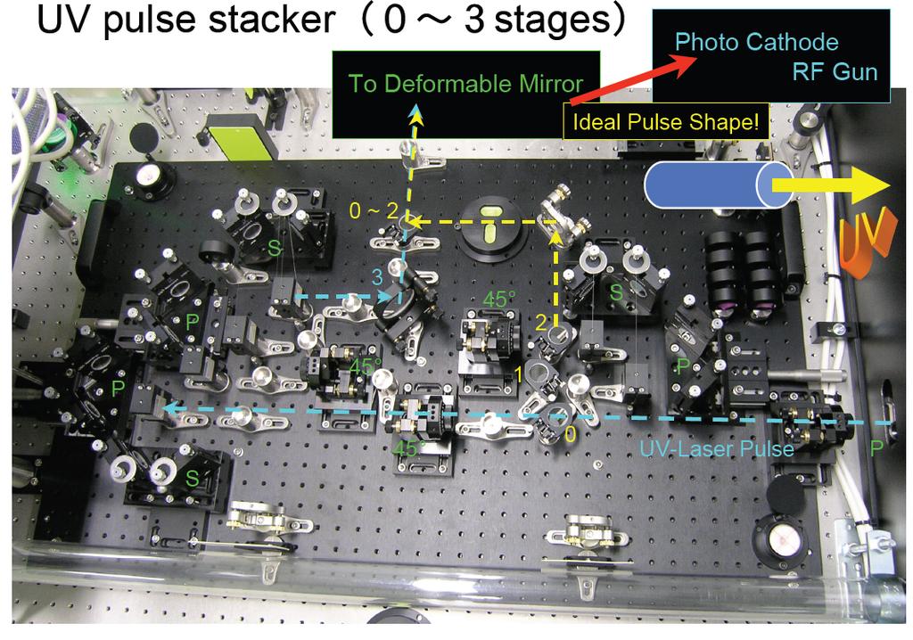
17 Temporal profile shaping (Pulse stacking) UV-Pulse Stacker S 2~3 ps λ/2 plate S P P S P S P S P S P Entrance window should be double AR-coated! Not utilize Brewster Window! The polarization of the input UV-laser is rotated 45 degrees by the half lambda waveplate. UV-laser is split into two equal portions by the each cubic polarizer. But, consider QE deference between S and P!! S P S P S P S P 16~24 ps
18 3. Optimization system of temporal profile Chirped pulse with deferent compressor length Changing compressor length, 2.5-ps original pulse is generated! Not that, laser pulse will be positively chirped & stretched through the silica material! S P S P To avoid interferences on the plateau of stacked macro pulse, S- and P- polarized pulses are alternatively positioned! S P S P Positive 20 ps Negative
19 Time chart of pulse stacking: 3 stages for generation of 20 ps square pulse 1/2 waveplate +45 time 10 ps 1 st Stage: S P 1/2 waveplate P S 2 nd Stage: 1/2 waveplate 3 rd Stage: 5 ps S P ps 2.5 ps 2.5 ps 2.5 ps S P S P S S 5 ps P If we mask the P-pulse at each stage; Easily shift to 10 ps, P, 5 ps! S P P


20 3. Optimization system of temporal profile Developed UV-Pulse Stacker


21 Two 6.5-ps stacked Pulses (14 ps between them) Shifting optical delay 1 All stacked together (15.5 ps FWHM)


22 Usage Photocathode with energy analyzer as a streak camera Temporal shift between S & P Spatial misalignment on the photocathode S P P S


23 Laser Optical Transport & Monitors AR- Entrance Window Bending Magnet Electron Energy Analyzer Laser Powermeter Electron Beam Profiler Variable Down Collimator Laser Profiler UV-Laser after 3D-shaped with DM &Pulse Stacker
24 ps between P-pol & S-pol ( in Measurements) P wave (MeV) S wave (MeV) Measured time deference between two beamlets:15ps Energy (MeV) RF phase (degree) Shifted optical delay with a length of 4.5 mm Energy (MeV) S-Pol was shifted to P-Pol! (In caliculation, shifted with phase of +15 degrees!) P wave (MeV) S wave (MeV) RF phase (degree)

25 Usage Photocathode with energy analyzer as a streak camera Original pulse is too short! Beamlets are not equivalently optimized! Pulse duration and intervals are optimized! Stacked Pulse duration: 20 ps ( Original pulse duration: 2.5 ps )

26 4. Emittance measurements D- Laser Beam Shape for experiment ~ present status at SPring-8 ~ Flattop : φ0.8 mm Square pulse:20 ps Q-scan emittance measurement Laser normal incidence

27 4. Emittance measurements 4-2. low emittance electron beam generation ~ we can provide low emittance beam for a month~ Accelerator system:26 MeV Result of emittance measurement: 2.0πmm nc Pulse duration:20 ps We are preparing experiment with further fine optimization of 3D-laser pulse for 2 month long.
28 4. Emittance measurements 4-3. low emittance electron beam generation ~ we are testing with different 3D-parameter ~ Result of emittance measurement: 2.0πmm nc Pulse duration:20 ps


!")
29 5. Summary and future plan ~ stable & reliable beam ~ A. We realized stable laser system Oscillator : 24 hours, 4.5 months, non-stop TW- Amp. : 24 hours, 1.5 months, non-stop THG: 1.4% rms stability for 1-day mesurments B. Automatically shaping Spatial Profile with DM + GA was successful! (Gaussian or Flattop) ~ Arbitrary Laser Shaping ~ ~ However, it takes 1 hour to optimize. C. Square pulse generation with UV-pulse stacker was successful at THG (263 nm)! Square Pulse: ~2-20 ps; Rising-time: ~ 700 fs D. Emittance:2.0πmmmm nc
30 A. Next shaping optics? ~ Holographic optics can 3D-shape in UV!? ~ DOE & HOE can be the goal of Laser shaping. However, we have to fix the structure of optics through steadying optimal pulse shape with adaptive optics!! Chromatic aberration is stronger than conventional optics. But, this characteristics can be used for temporal pulse shaping!?


31 How to get more efficiency?


32 A. Both profiles shaping with Fiber Bundle ~ FB can 3D-shape the UV-pulse & make easy to transport ~ Cable Strand Microlens Array Silica Fiber Bundle


 Fiber")

33 A. Both profiles shaping with Fiber Bundle ~ Transparent Cathode with Fiber Bundle ~ Pulse Stacking with 2,000 different Optical Passes Transparent Cathode for backward illumination UV-Laser (266nm) Fiber Bundle: Length: 2.0 m Bundle size:12 mm No. of Fibers:1967


34 A. Both profiles shaping with Fiber Bundle 1. Results of spatial profiles with shaping Spatially homogenizing is very strong with FB Any kind of bad profile can be corrected! Pulse shaping & stretching with FB is pulse-stacking Depend on the length and mapping of FB Fiber-Shaping (1m long)


35 A. Both profiles shaping with Fiber Bundle 2. Results of temporal profiles with shaping ~ Pulse shaping result due to mainly Pulse Staking effect ~ Width (FWHM): 16 ps Fiber Bindle Length: 1 m Mapping: Random Input UV-pulse energy: down to 60 nj
36 Closed Control System for Fiber Bundle with computer-aided Deformable mirror PC Profile Data PC for control Deformable mirror and Evaluate resulting Laser Profile Electron Beam Profile OR Video Signal Control DM Fiber Bundle (0.5~1m) Lens CCD sensor (LBA-PC) Laser Light source (THG: 263nm) Deformable mirror
37 A. Summary of Fiber Bundle Shaping Shaping with computer-aided deformable mirror could generate Flattop. It is very flexible to optimize the spatial profile (electron bunch) with genetic algorithm. Fiber Bundle is ideal as a 3D-shaper It is very simple to shape : You have to optimize the length of the Bundle for aimed pulse duration: 15 ps ~ 1-m long 3D-laser profile: It can generate ellipsoidal from any profile. Short working distance: It needs to develop back illumination. Laser fluence limit: Laser 100 fs <1.5 mj/cm2 It is possible to use as 3D-shaper down to 60 nj/pulse. Transparent cathode for shaping complex system with fixed fiber bundle & adjustable deformable mirror might have a lot of possibilities with fine tuning.
3D- Laser pulse shaping System to Minimize Emittance for Photocathode RF gun ~ toward to the highest brightness of electron beam source ~
 Adaptive 3D- Laser pulse shaping System to Minimize Emittance for Photocathode RF gun ~ toward to the highest brightness of electron beam source ~ Hiromistu Tomizawa Accelerator Division, Japan Synchrotron
Development of reliable and sophisticated photo injector system and future plan
 Development of reliable and sophisticated photo injector system and future plan Hiromitsu Tomizawa Accelerator Division, Japan Synchrotron Radiation Research Institute (JASRI/SPring-8) Kouto, Sayo-cho,
Diagnostic Systems for Characterizing Electron Sources at the Photo Injector Test Facility at DESY, Zeuthen site
 1 Diagnostic Systems for Characterizing Electron Sources at the Photo Injector Test Facility at DESY, Zeuthen site Sakhorn Rimjaem (on behalf of the PITZ team) Motivation Photo Injector Test Facility at
Phenomena related to the laser incidence on the cathode surface
 Phenomena related to the laser incidence on the cathode surface Hiromistu Tomizawa Accelerator Division, Japan Synchrotron Radiation Research Institute (SPring-8) These topics have been discussed in LAAA
Dark Current at Injector. Jang-Hui Han 27 November 2006 XFEL Beam Dynamics Meeting
 Dark Current at Injector Jang-Hui Han 27 November 2006 XFEL Beam Dynamics Meeting Considerations for the guns Ultra-low slice emittance of electron beams higher gradient at the gun cavity solenoid field
Experimental Optimization of Electron Beams for Generating THz CTR and CDR with PITZ
 Experimental Optimization of Electron Beams for Generating THz CTR and CDR with PITZ Introduction Outline Optimization of Electron Beams Calculations of CTR/CDR Pulse Energy Summary & Outlook Prach Boonpornprasert
Commissioning of the new Injector Laser System for the Short Pulse Project at FLASH
 Commissioning of the new Injector Laser System for the Short Pulse Project at FLASH Uni Hamburg tim.plath@desy.de 05.11.2013 Supported by BMBF under contract 05K10GU2 & FS FLASH 301 Motivation short pulses
Hiromitsu TOMIZAWA XFEL Division /SPring-8
 TUPLB10 (Poster: TUPB080) Non-destructive Real-time Monitor to measure 3D- Bunch Charge Distribution with Arrival Timing to maximize 3D-overlapping for HHG-seeded EUV-FEL Hiromitsu TOMIZAWA XFEL Division
Jitter measurement by electro-optical sampling
 Jitter measurement by electro-optical sampling VUV-FEL at DESY - Armin Azima S. Duesterer, J. Feldhaus, H. Schlarb, H. Redlin, B. Steffen, DESY Hamburg K. Sengstock, Uni Hamburg Adrian Cavalieri, David
Simulations of the IR/THz Options at PITZ (High-gain FEL and CTR)
") Case Study of IR/THz source for Pump-Probe Experiment at the European XFEL Simulations of the IR/THz Options at PITZ (High-gain FEL and CTR) Introduction Outline Simulations of High-gain FEL (SASE) Simulation
Case Study of IR/THz source for Pump-Probe Experiment at the European XFEL Simulations of the IR/THz Options at PITZ (High-gain FEL and CTR) Introduction Outline Simulations of High-gain FEL (SASE) Simulation
Motivation of emission studies at PITZ
 Motivation of emission studies at PITZ PITZ activities to understand the discrepancies between measurements and simulations in: Transverse phase space Optimum machine parameters Auxiliary measurements
Short Pulse, Low charge Operation of the LCLS. Josef Frisch for the LCLS Commissioning Team
 Short Pulse, Low charge Operation of the LCLS Josef Frisch for the LCLS Commissioning Team 1 Normal LCLS Parameters First Lasing in April 10, 2009 Beam to AMO experiment August 18 2009. Expect first user
MEASUREMENT OF TEMPORAL RESOLUTION AND DETECTION EFFICIENCY OF X-RAY STREAK CAMERA BY SINGLE PHOTON IMAGES
 Proceedings of IBIC212, Tsukuba, Japan MEASUREMENT OF TEMPORAL RESOLUTION AND DETECTION EFFICIENCY OF X-RAY STREAK CAMERA BY SINGLE PHOTON IMAGES A. Mochihashi, M. Masaki, S. Takano, K. Tamura, H. Ohkuma,
INVESTIGATIONS OF THE DISTRIBUTION IN VERY SHORT ELECTRON BUNCHES LONGITUDINAL CHARGE
 INVESTIGATIONS OF THE LONGITUDINAL CHARGE DISTRIBUTION IN VERY SHORT ELECTRON BUNCHES Markus Hüning III. Physikalisches Institut RWTH Aachen IIIa and DESY Invited talk at the DIPAC 2001 Methods to obtain
Photo Injector Test facility at DESY, Zeuthen site
 Photo Injector Test facility at DESY, Zeuthen site PITZ EXPERIENCE ON THE EXPERIMENTAL OPTIMIZATION OF THE RF PHOTO INJECTOR FOR THE EUROPEAN XFEL Mikhail Krasilnikov (DESY) for the PITZ Team FEL 2013
Development of Cs 2 Te photocathode RF gun system for compact THz SASE-FEL
 Development of Cs 2 Te photocathode RF gun system for compact THz SASE-FEL R. Kuroda, H. Ogawa, N. Sei, H. Toyokawa, K. Yagi-Watanabe, M. Yasumoto, M. Koike, K. Yamada, T. Yanagida*, T. Nakajyo*, F. Sakai*
1. Beam based alignment Laser alignment Solenoid alignment 2. Dark current 3. Thermal emittance
 Beam based alignment, Dark current and Thermal emittance measurements J-H.Han,M.Krasilnikov,V.Miltchev, PITZ, DESY, Zeuthen 1. Beam based alignment Laser alignment Solenoid alignment 2. Dark current 3.
Simulations of the IR/THz source at PITZ (SASE FEL and CTR)
") Simulations of the IR/THz source at PITZ (SASE FEL and CTR) Introduction Outline Simulations of SASE FEL Simulations of CTR Summary Issues for Discussion Mini-Workshop on THz Option at PITZ DESY, Zeuthen
Simulations of the IR/THz source at PITZ (SASE FEL and CTR) Introduction Outline Simulations of SASE FEL Simulations of CTR Summary Issues for Discussion Mini-Workshop on THz Option at PITZ DESY, Zeuthen
Introduction to the benchmark problem
 Introduction to the benchmark problem M. Krasilnikov (DESY) Working group 4: Low emittance electron guns 37th ICFA Beam Dynamics Workshop Future Light Sources 15 19 May 6 DESY, Hamburg, Germany Outline
RF-Gun Experience at PITZ - Longitudinal Phase Space
 - Collaboration meeting 9th of October 2006 Hamburg University Juliane Rönsch 1 Motivation special device to measure the longitudinal phase space at low momentum typical high energy diagnostics can not
Emittance and Quantum Efficiency Measurements from a 1.6 cell S- Band Photocathode RF Gun with Mg Cathode *
 LCLS-TN-4-3 SLAC PUB 763 September, 4 Emittance and Quantum Efficiency Measurements from a.6 cell S- Band Photocathode RF Gun with Mg Cathode * J.F. Schmerge, J.M. Castro, J.E. Clendenin, D.H. Dowell,
Diagnostic Systems for High Brightness Electron Injectors
 Diagnostic Systems for High Brightness Electron Injectors Henrik Loos 48 th ICFA Advanced Beam Dynamics Workshop on Future Light Sources SLAC 2010 1 1 Henrik Loos LCLS Injector Injector Diagnostics Characterize
Transverse emittance measurements on an S-band photocathode rf electron gun * Abstract
 SLAC PUB 8963 LCLS-01-06 October 2001 Transverse emittance measurements on an S-band photocathode rf electron gun * J.F. Schmerge, P.R. Bolton, J.E. Clendenin, F.-J. Decker, D.H. Dowell, S.M. Gierman,
Ellipsoidal Laser Status & Results Introduction Laser system & on-table data Results Redesign Outlook
 Ellipsoidal Laser Status & Results Introduction Laser system & on-table data Results Redesign Outlook James Good PITZ Collaboration Meeting 14 Jun 2017 Introduction > Motivation: Further improvement of
SRF GUN CHARACTERIZATION - PHASE SPACE AND DARK CURRENT MEASUREMENTS AT ELBE*
 SRF GUN CHARACTERIZATION - PHASE SPACE AND DARK CURRENT MEASUREMENTS AT ELBE* E. Panofski #, A. Jankowiak, T. Kamps, Helmholtz-Zentrum Berlin, Berlin, Germany P.N. Lu, J. Teichert, Helmholtz-Zentrum Dresden-Rossendorf,
Experimental Measurements of the ORION Photoinjector Drive Laser Oscillator Subsystem
 Experimental Measurements of the ORION Photoinjector Drive Laser Oscillator Subsystem D.T Palmer and R. Akre Laser Issues for Electron RF Photoinjectors October 23-25, 2002 Stanford Linear Accelerator
Investigations on the electron bunch distribution in the longitudinal phase space at a laser driven RF-electron source for the European X-FEL
 Juliane Rönsch Universität Hamburg / DESY Investigations on the electron bunch distribution in the longitudinal phase space at a laser driven RF-electron source for the European X-FEL 5/27/2009 1 Contents
Start-to-End Simulations
 AKBP 9.3 Case Study for 100 µm SASE FEL Based on PITZ Accelerator for Pump-Probe Experiment at the European XFEL Start-to-End Simulations Outline Introduction Beam Optimization Beam Transport Simulation
High Accuracy Adaptive (transverse) Laser and Electron Beam Shaping. Jared Maxson Cornell University ERL 2015, BNL
 Laser and Electron Beam Shaping. Jared Maxson Cornell University ERL 2015, BNL") High Accuracy Adaptive (transverse) Laser and Electron Beam Shaping and a bit about DC gun emittance vs. gun gap Jared Maxson Cornell University ERL 2015, BNL Outline I. Motivation: Why do you want from
High Accuracy Adaptive (transverse) Laser and Electron Beam Shaping and a bit about DC gun emittance vs. gun gap Jared Maxson Cornell University ERL 2015, BNL Outline I. Motivation: Why do you want from
Low slice emittance preservation during bunch compression
 Low slice emittance preservation during bunch compression S. Bettoni M. Aiba, B. Beutner, M. Pedrozzi, E. Prat, S. Reiche, T. Schietinger Outline. Introduction. Experimental studies a. Measurement procedure
ASTRA BASED SWARM OPTIMIZATIONS OF THE BERLinPro INJECTOR
 ASTRA BASED SWARM OPTIMIZATIONS OF THE BERLinPro INJECTOR M. Abo-Bakr FRAAC4 Michael Abo-Bakr 2012 ICAP Warnemünde 1 Content: Introduction ERL s Introduction BERLinPro Motivation Computational Aspects
AREAL Test Facility for Advanced Accelerator and Radiation Sources Concepts
 2 nd European Advanced Accelerator Concepts AREAL Test Facility for Advanced Accelerator and Radiation Sources Concepts V. Tsakanov CANDLE SRI 13-19 Sep 2015, La Biodola, Isola d'elba Introduction 2nd
3D Laser Pulse Shaping for the Cornell ERL Photoinjector. August 9 th, 2012 Sierra Cook Advisors: Adam Bartnik, Ivan Bazarov, Jared Maxson
 3D Laser Pulse Shaping for the Cornell ERL Photoinjector August 9 th, 2012 Sierra Cook Advisors: Adam Bartnik, Ivan Bazarov, Jared Maxson Energy Recovery Linac (ERL) Accelerating Bunch Decelerating Bunch
Multivariate Optimization of High Brightness High Current DC Photoinjector. Ivan Bazarov
 Multivariate Optimization of High Brightness High Current DC Photoinjector Ivan Bazarov Talk Outline: Motivation Evolutionary Algorithms Optimization Results 1 ERL Injector 750 kv DC Gun Goal: provide
Beam dynamics studies for PITZ using a 3D full-wave Lienard-Wiechert PP code
 Beam dynamics studies for PITZ using a 3D full-wave Lienard-Wiechert PP code Y. Chen, E. Gjonaj, H. De Gersem, T. Weiland TEMF, Technische Universität Darmstadt, Germany DESY-TEMF Collaboration Meeting
ASTRA simulations of the slice longitudinal momentum spread along the beamline for PITZ
 ASTRA simulations of the slice longitudinal momentum spread along the beamline for PITZ Orlova Ksenia Lomonosov Moscow State University GSP-, Leninskie Gory, Moscow, 11999, Russian Federation Email: ks13orl@list.ru
Generation and characterization of ultra-short electron and x-ray x pulses
 Generation and characterization of ultra-short electron and x-ray x pulses Zhirong Huang (SLAC) Compact XFEL workshop July 19-20, 2010, Shanghai, China Ultra-bright Promise of XFELs Ultra-fast LCLS Methods
Injector Experimental Progress
 Injector Experimental Progress LCLS TAC Meeting December 10-11 2001 John Schmerge for the GTF Team GTF Group John Schmerge Paul Bolton Steve Gierman Cecile Limborg Brendan Murphy Dave Dowell Leader Laser
LCLS Injector Prototyping at the GTF
 LCLS Injector Prototyping at at the GTF John John Schmerge, SLAC SLAC November 3, 3, 23 23 GTF GTF Description Summary of of Previous Measurements Longitudinal Emittance Transverse Emittance Active LCLS
Free-electron laser SACLA and its basic. Yuji Otake, on behalf of the members of XFEL R&D division RIKEN SPring-8 Center
 Free-electron laser SACLA and its basic Yuji Otake, on behalf of the members of XFEL R&D division RIKEN SPring-8 Center Light and Its Wavelength, Sizes of Material Virus Mosquito Protein Bacteria Atom
II) Experimental Design
 Experimental Design") SLAC Experimental Advisory Committee --- September 12 th, 1997 II) Experimental Design Theory and simulations Great promise of significant scientific and technological achievements! How to realize this
SLAC Experimental Advisory Committee --- September 12 th, 1997 II) Experimental Design Theory and simulations Great promise of significant scientific and technological achievements! How to realize this
Beam manipulation with high energy laser in accelerator-based light sources
 Beam manipulation with high energy laser in accelerator-based light sources Ming-Chang Chou High Brightness Injector Group FEL winter school, Jan. 29 ~ Feb. 2, 2018 Outline I. Laser basic II. III. IV.
Developments for the FEL user facility
 Developments for the FEL user facility J. Feldhaus HASYLAB at DESY, Hamburg, Germany Design and construction has started for the FEL user facility including the radiation transport to the experimental
Optics.
 Optics www.optics.rochester.edu/classes/opt100/opt100page.html Course outline Light is a Ray (Geometrical Optics) 1. Nature of light 2. Production and measurement of light 3. Geometrical optics 4. Matrix
FURTHER UNDERSTANDING THE LCLS INJECTOR EMITTANCE*
 Proceedings of FEL014, Basel, Switzerland FURTHER UNDERSTANDING THE LCLS INJECTOR EMITTANCE* F. Zhou, K. Bane, Y. Ding, Z. Huang, and H. Loos, SLAC, Menlo Park, CA 9405, USA Abstract Coherent optical transition
Simulations for photoinjectors C.Limborg
 Simulations for photoinjectors C.Limborg 1- GTF Simulations Parmela modeling improvements Comparison to experimental results: 2ps & 4ps Sensitivity study Plans for future simulations 2- LCLS Injector Simulations
Time resolved transverse and longitudinal phase space measurements at the high brightness photo injector PITZ
 Time resolved transverse and longitudinal phase space measurements at the high brightness photo injector PITZ 1. Motivation 2. Transverse deflecting structure 3. Longitudinal phase space tomography 4.
R&D experiments at BNL to address the associated issues in the Cascading HGHG scheme
 R&D experiments at BNL to address the associated issues in the Cascading HGHG scheme Li Hua Yu for DUV-FEL Team National Synchrotron Light Source Brookhaven National Laboratory FEL2004 Outline The DUVFEL
S2E (Start-to-End) Simulations for PAL-FEL. Eun-San Kim
 Simulations for PAL-FEL. Eun-San Kim") S2E (Start-to-End) Simulations for PAL-FEL Aug. 25 2008 Kyungpook Nat l Univ. Eun-San Kim 1 Contents I Lattice and layout for a 10 GeV linac II Beam parameters and distributions III Pulse-to-pulse stability
S2E (Start-to-End) Simulations for PAL-FEL Aug. 25 2008 Kyungpook Nat l Univ. Eun-San Kim 1 Contents I Lattice and layout for a 10 GeV linac II Beam parameters and distributions III Pulse-to-pulse stability
Photo Injector Test facility at DESY, Zeuthen site. PITZ: facility overview
 Photo Injector Test facility at DESY, Zeuthen site. PITZ: facility overview Mikhail Krasilnikov (DESY) for the PITZ Team Mini-workshop on THz option at PITZ, Zeuthen, 22.09.2015 Photo Injector Test facility
O rion. The ORION Facility at SLAC. Bob Siemann AAC Workshop, June 15, 2000
 The ORION Facility at SLAC Bob Siemann AAC Workshop, June 15, 2000 1. Introduction 2. The ORION Workshop 3. What s Next? 4. Concluding Remarks http://www-project.slac.stanford.edu/orion/ Introduction Advanced
Velocity Bunching Studies at FLASH. Bolko Beutner, DESY XFEL Beam Dynamics Meeting
 Velocity Bunching Studies at FLASH Contents Introduction ASTRA simulations Semi-Analytic Model CSR microbunch instability studies Experiments at FLASH Summary and Outlook Introduction At low beam energies
The New Superconducting RF Photoinjector a High-Average Current & High-Brightness Gun
 The New Superconducting RF Photoinjector a High-Average Current & High-Brightness Gun Jochen Teichert for the BESSY-DESY-FZD-MBI collaboration and the ELBE crew High-Power Workshop, UCLA, Los Angeles 14
Juliane Rönsch Hamburg University. Investigations of the longitudinal phase space at a photo injector for the X-FEL
 Juliane Rönsch Hamburg University Investigations of the longitudinal phase space at a photo injector for the X-FEL Juliane Rönsch 1/15/28 1 Contents Introduction PITZ Longitudinal phase space of a photoinjector
Working Group 8 Laser Technology for Laser-Plasma Accelerators Co-leaders Bill White & Marcus Babzien
 Working Group 8 Laser Technology for Laser-Plasma Accelerators Co-leaders Bill White & Marcus Babzien Working Group 8: Overview Relatively small group this year: 8 oral / 3 poster presentations For 2016
ICFA ERL Workshop Jefferson Laboratory March 19-23, 2005 Working Group 1 summary Ilan Ben-Zvi & Ivan Bazarov
 ICFA ERL Workshop Jefferson Laboratory March 19-23, 2005 Working Group 1 summary Ilan Ben-Zvi & Ivan Bazarov Sincere thanks to all WG1 participants: Largest group, very active participation. This summary
LOLA: Past, present and future operation
 LOLA: Past, present and future operation FLASH Seminar 1/2/29 Christopher Gerth, DESY 8/5/29 FLASH Seminar Christopher Gerth 1 Outline Past Present Future 8/5/29 FLASH Seminar Christopher Gerth 2 Past
Alignment requirement for the SRF cavities of the LCLS-II injector LCLSII-TN /16/2014
 Alignment requirement for the SRF cavities of the LCLS-II injector LCLS-II TN-14-16 12/16/2014 R. K. Li, C. Papadopoulos, T. O. Raubenheimer, J. F. Schmerge, and F. Zhou December 16, 2014 LCLSII-TN-14-16
Linac optimisation for the New Light Source
 Linac optimisation for the New Light Source NLS source requirements Electron beam requirements for seeded cascade harmonic generation LINAC optimisation (2BC vs 3 BC) CSR issues energy chirp issues jitter
TTF and VUV-FEL Injector Commissioning
 TESLA Collaboration Meeting Sep. 6-8, 2004 Orsay TTF and VUV-FEL Injector Commissioning Siegfried Schreiber, Klaus Floettmann DESY Brief description of the injector Basic measurements Preliminary results
Layout of the HHG seeding experiment at FLASH
 Layout of the HHG seeding experiment at FLASH V. Miltchev on behalf of the sflash team: A. Azima, J. Bödewadt, H. Delsim-Hashemi, M. Drescher, S. Düsterer, J. Feldhaus, R. Ischebeck, S. Khan, T. Laarmann
Expected properties of the radiation from VUV-FEL / femtosecond mode of operation / E.L. Saldin, E.A. Schneidmiller, M.V. Yurkov
 Expected properties of the radiation from VUV-FEL / femtosecond mode of operation / E.L. Saldin, E.A. Schneidmiller, M.V. Yurkov TESLA Collaboration Meeting, September 6-8, 2004 Experience from TTF FEL,
Ultra-Short Low Charge Operation at FLASH and the European XFEL
 Ultra-Short Low Charge Operation at FLASH and the uropean XFL Igor Zagorodnov DSY, Hamburg, Germany 5.8. The 3nd FL Conference, Malmö Outline FLASH layout and desired beam parameters Technical constraints
4GLS Status. Susan L Smith ASTeC Daresbury Laboratory
 4GLS Status Susan L Smith ASTeC Daresbury Laboratory Contents ERLP Introduction Status (Kit on site ) Plan 4GLS (Conceptual Design) Concept Beam transport Injectors SC RF FELs Combining Sources May 2006
Transverse Beam Optics of the FLASH Facility
 Transverse Beam Optics of the FLASH Facility ( current status and possible updates ) Nina Golubeva and Vladimir Balandin XFEL Beam Dynamics Group Meeting, 18 June 2007 Outline Different optics solutions
Introduction. Thermoionic gun vs RF photo gun Magnetic compression vs Velocity bunching. Probe beam design options
 Introduction Following the 19/05/04 meeting at CERN about the "CTF3 accelerated programme", a possible french contribution has been envisaged to the 200 MeV Probe Beam Linac Two machine options were suggested,
Beam Dynamics and SASE Simulations for XFEL. Igor Zagorodnov DESY
 Beam Dynamics and SASE Simulations for XFEL Igor Zagorodnov 4.. DESY Beam dynamics simulations for the European XFEL Full 3D simulation method ( CPU, ~ hours) Gun LH M, M,3 E = 3 MeV E = 7 MeV E 3 = 4
SwissFEL INJECTOR DESIGN: AN AUTOMATIC PROCEDURE
 Proceedings of FEL03, New York, NY, USA SwissFEL INJECTOR DESIGN: AN AUTOMATIC PROCEDURE S. Bettoni, M. Pedrozzi, S. Reiche, PSI, Villigen, Switzerland Abstract The first section of FEL injectors driven
Accelerator Physics Issues of ERL Prototype
 Accelerator Physics Issues of ERL Prototype Ivan Bazarov, Geoffrey Krafft Cornell University TJNAF ERL site visit (Mar 7-8, ) Part I (Bazarov). Optics. Space Charge Emittance Compensation in the Injector
AREAL. Test Facility for Advanced Accelerator and Radiation Sources Concepts. Part.1 Introduction. V. Tsakanov CANDLE SRI
 AREAL Test Facility for Advanced Accelerator and Radiation Sources Concepts Part.1 Introduction V. Tsakanov CANDLE SRI 01 October 2015 2 nd European Advanced Accelerator Concepts 13-19 Sep 2015, Isola
Optimum beam creation in photoinjectors using spacecharge expansion II: experiment
 Optimum beam creation in photoinjectors using spacecharge expansion II: experiment J. Rosenzweig, A. Cook, M. Dunning, R.J. England, G. Travish, UCLA P. Musumeci, C. Vicario, D. Filippetto, M. Ferrario,
SPARCLAB. Source For Plasma Accelerators and Radiation Compton with Laser And Beam
 SPARCLAB Source For Plasma Accelerators and Radiation Compton with Laser And Beam EMITTANCE X X X X X X X X Introduction to SPARC_LAB 2 BRIGHTNESS (electrons) B n 2I nx ny A m 2 rad 2 The current can be
Research Laboratory for Quantum Beam Science
 L band Linac 60 Co γ ray irradiation facility Research Laboratory for Quantum Beam Science http://www.sanken.osaka u.ac.jp/labs/rl/ S band Laser Photocathode RF Linac ISIR, Osaka University 150 MeV S band
CHARA Meeting 2017 Pasadena, California
 MORE AUTOMATION Laszlo Sturmann M7 ACTUATORS LAB. LASER ALIGNMENT TELESCOPE OPTICAL ALIGNMENT NEW ACTUATORS REMOTELY ACTUATED M7 MOUNT MOTIVATION THE PRECISION OF THE COUDE ALIGNMENT WAS NOT SUFFICIENT
Single-shot Ultrafast Electron Microscopy
 Single-shot Ultrafast Electron Microscopy Renkai Li and Pietro Musumeci Department of Physics and Astronomy, UCLA 25 th North American Particle Accelerator Conference Sep 30 - Oct 4, 2013, Pasadena, CA,
Dispersion and how to control it
 Dispersion and how to control it Group velocity versus phase velocity Angular dispersion Prism sequences Grating pairs Chirped mirrors Intracavity and extra-cavity examples 1 Pulse propagation and broadening
Accelerator Activities at PITZ
 Accelerator Activities at PITZ Plasma acceleration etc. Outline > Motivation / Accelerator Research & Development (ARD) > Plasma acceleration Basic Principles Activities SINBAD > ps-fs electron and photon
gives rise to multitude of four-wave-mixing phenomena which are of great
 Module 4 : Third order nonlinear optical processes Lecture 26 : Third-order nonlinearity measurement techniques: Z-Scan Objectives In this lecture you will learn the following Theory of Z-scan technique
Development of Soft X-rayX using Laser Compton Scattering
 26 th Advanced ICFA Beam Dynamics Workshop on Nanometre-Size Colliding Beams September 2-6, 2002 at Lausanne Development of Soft X-rayX Source using Laser Compton Scattering R. Kuroda*, S. Kashiwagi*,
A Multi-beamlet Injector for Heavy Ion Fusion: Experiments and Modeling
 A Multi-beamlet Injector for Heavy Ion Fusion: Experiments and Modeling G.A. Westenskow, D.P. Grote; LLNL J.W. Kwan, F. Bieniosek; LBNL PAC07 - FRYAB01 Albuquerque, New Mexico June 29, 2007 This work has
Excitements and Challenges for Future Light Sources Based on X-Ray FELs
 Excitements and Challenges for Future Light Sources Based on X-Ray FELs 26th ADVANCED ICFA BEAM DYNAMICS WORKSHOP ON NANOMETRE-SIZE COLLIDING BEAMS Kwang-Je Kim Argonne National Laboratory and The University
H. Maesaka*, H. Ego, T. Hara, A. Higashiya, S. Inoue, S. Matsubara, T. Ohshima, K. Tamasaku, H. Tanaka, T. Tanikawa, T. Togashi, K. Togawa, H.
 H. Maesaka*, H. Ego, T. Hara, A. Higashiya, S. Inoue, S. Matsubara, T. Ohshima, K. Tamasaku, H. Tanaka, T. Tanikawa, T. Togashi, K. Togawa, H. Tomizawa, M. Yabashi, K. Yanagida, T. Shintake and Y. Otake
SUPPLEMENTARY INFORMATION
 doi:1.138/nature1878 I. Experimental setup OPA, DFG Ti:Sa Oscillator, Amplifier PD U DC U Analyzer HV Energy analyzer MCP PS CCD Polarizer UHV Figure S1: Experimental setup used in mid infrared photoemission
Microbunching Workshop 2010 March 24, 2010, Frascati, Italy. Zhirong Huang
 Measurements of the LCLS Laser Heater and its impact on the LCLS FEL Performance Z. Huang for the LCLS commissioning team LCLS 1 1 Outline Introduction LCLS setup and measurements Effects on FEL performance
Longitudinal Measurements at the SLAC Gun Test Facility*
 SLAC-PUB-9541 September Longitudinal Measurements at the SLAC Gun Test Facility* D. H. Dowell, P. R. Bolton, J.E. Clendenin, P. Emma, S.M. Gierman, C.G. Limborg, B.F. Murphy, J.F. Schmerge Stanford Linear
UV laser pulse temporal profile requirements for the LCLS injector - Part I - Fourier Transform limit for a temporal zero slope flattop
 UV laser pulse temporal profile requirements for the LCLS injector - Part I - Fourier Transform limit for a temporal zero slope flattop C. Limborg-Deprey and P.R. Bolton, Stanford Linear Accelerator Center,
The SCSS test accelerator Free-Electron Laser seeded by harmonics produced in gas
 UVX 2008 (2009) 85 91 C EDP Sciences, 2009 DOI: 10.1051/uvx/2009014 The SCSS test accelerator Free-Electron Laser seeded by harmonics produced in gas G. Lambert 1,T.Hara 2, T. Tanikawa 3, D. Garzella 4,
The design for the LCLS rf photo-injector
 SLAC-PUB-8054 January 1999 The design for the LCLS rf photo-injector R. Alley, V. Bharadwaj, J. Clendenin, P. Emma, A. Fisher, J. Frisch, T. Kotseroglou, R. Miller, D. T. Palmer, J. Schmerge, J. C. Sheppard,
Femto second X ray Pulse Generation by Electron Beam Slicing. F. Willeke, L.H. Yu, NSLSII, BNL, Upton, NY 11973, USA
 Femto second X ray Pulse Generation by Electron Beam Slicing F. Willeke, L.H. Yu, NSLSII, BNL, Upton, NY 11973, USA r 2 r 1 y d x z v Basic Idea: When short electron bunch from linac (5MeV, 50pC,100fs)
Dark current at the Euro-XFEL
 Dark current at the Euro-XFEL Jang-Hui Han DESY, MPY Observations at PITZ and FLASH Estimation for the European XFEL Ideas to reduce dark current at the gun DC at FLASH RF gun M1 M2 M3 M4 M5 M6 M7 6 undulator
Modeling of the secondary electron emission in rf photocathode guns
 Modeling of the secondary electron emission in rf photocathode guns J.-H. Han, DESY Zeuthen 8 June 2004 Joint Uni. Hamburg and DESY Accelerator Physics Seminar Contents 1. Necessity of secondary electron
High average current photo injector (PHIN) for the CLIC Test Facility at CERN
 for the CLIC Test Facility at CERN") High average current photo injector (PHIN) for the CLIC Test Facility at CERN CLIC and CTF3 motivation Photo injectors, PHIN Emittance measurements Long pulse operation, time resolved measurements Cathode
High average current photo injector (PHIN) for the CLIC Test Facility at CERN CLIC and CTF3 motivation Photo injectors, PHIN Emittance measurements Long pulse operation, time resolved measurements Cathode
EO single-shot temporal measurements of electron bunches
 EO single-shot temporal measurements of electron bunches and of terahertz CSR and FEL pulses. Steven Jamison, Giel Berden, Allan MacLeod Allan Gillespie, Dino Jaroszynski, Britta Redlich, Lex van der Meer
Using IMPACT T to perform an optimization of a DC gun system Including merger
 Using IMPACT T to perform an optimization of a DC gun system Including merger Xiaowei Dong and Michael Borland Argonne National Laboratory Presented at ERL09 workshop June 10th, 2009 Introduction An energy
Studies on charge production from Cs 2 Te photocathodes in the PITZ L-band normal conducting radio frequency photo injector
 Studies on charge production from Cs 2 Te photocathodes in the PITZ L-band normal conducting radio frequency photo injector C. Hernandez-Garcia 1, M. Kraslinikov, G. Asova 2, M. Bakr 3, P. Boonpornprasert,
Supplemental material for Bound electron nonlinearity beyond the ionization threshold
 Supplemental material for Bound electron nonlinearity beyond the ionization threshold 1. Experimental setup The laser used in the experiments is a λ=800 nm Ti:Sapphire amplifier producing 42 fs, 10 mj
Low energy high brilliance beam characterization
 Low energy high brilliance beam characterization J. Bähr, DESY, Zeuthen, Germany Abstract Low energy high brilliance beam characterization plays an important role for electron sources and injectors of
VELA/CLARA as Advanced Accelerator Studies Test-bed at Daresbury Lab.
 VELA/CLARA as Advanced Accelerator Studies Test-bed at Daresbury Lab. Yuri Saveliev on behalf of VELA and CLARA teams STFC, ASTeC, Cockcroft Institute Daresbury Lab., UK Outline VELA (Versatile Electron
What have we learned from the LCLS injector?*
 SLAC-PUB-14644 LCLS-TN-11-4 October 19, 2011 What have we learned from the LCLS injector?* Feng Zhou and Axel Brachmann for the LCLS injector team The LCLS injector reliably delivered a high quality electron
Undulator radiation from electrons randomly distributed in a bunch
 Undulator radiation from electrons randomly distributed in a bunch Normally z el >> N u 1 Chaotic light Spectral property is the same as that of a single electron /=1/N u Temporal phase space area z ~(/