UV laser pulse temporal profile requirements for the LCLS injector - Part I - Fourier Transform limit for a temporal zero slope flattop
|
|
|
- Avis Blake
- 5 years ago
- Views:
Transcription
1 UV laser pulse temporal profile requirements for the LCLS injector - Part I - Fourier Transform limit for a temporal zero slope flattop C. Limborg-Deprey and P.R. Bolton, Stanford Linear Accelerator Center, MS 18, 575 Sand Hill Road Menlo Park, California Abstract: The temporal profile of the uv drive laser pulse for the LCLS injector is specified by the duration, the rise/fall time, and the maximum rms amplitude (for all frequencies) of residual modulation in the plateau region. The bandwidth of the uv laser system should accommodate pulses with a rise/fall time as low as 0.7 ps and an rms residual amplitude modulation (on the plateau) below 0.5% in the absence of a laser heater. Computations including the laser heater [3] relax this requirement to the 5% level. Numerical analyses of Fourier transform limited uv pulses show that the extent of frequency sidebands should extend to at least 1.5 THz on either side of the central uv frequency. For simplicity, we assume that the emitted electron beam profile matches the laser profile. The evolution of those electron beam distributions in the longitudinal phase space along the beamline as calculated with PARMELA/ASTRA are shown. Related spectral and shaping requirements on the fundamental ir pulses are briefly addressed. I - Introduction: For reaching gain saturation at 1.5-A in the LCLS FEL, the slice emittance of the electron beam needs to be less 1. µm, the peak current more than 3.4 ka, and the slice energy spread smaller than.10-4 at the entrance of the undulator. To reach those goal parameters, the injector has to provide a beam with slice emittance smaller than 1 µm and a projected emittance of less than 1. µm for a 1nC, 10ps long electron bunch. A slice emittance corresponds to the emittance of particles contained in a longitudinal slice whose length is 1% of the total bunch length. The choice of 1% slices along the bunch has been chosen because it is the cooperation length in the undulator during the Self_Amplification of SpontaneousEmission (SASE).. In order to accommodate emittance growth in the linac and bunch compressors, emittance values targeted for the injector are obviously more restrictive than those required at the entrance of the undulator. Accordingly, the emittance values targeted at the end of the injector, with computations performed for an idealized machine, are in fact less than 1.0µm for the projected emittance and less than 0.9µm for the 80%-emittance, leaving some room for the emittance growth due to field errors[1]. The next paragraph defines the various emittance quantities. It can be skipped by the person familiar with them. The total projected emittance is given by
2 ε proj. = i x i i x i x p x p in which the quantities <> are averaged over all particles i in the bunch. The 80%-emittance is computed using averaging over the particles contained in the 80 core slices out of 100 longitudinal slices along the bunch. It can be expressed similarly as ε 80 = i x i i x i x p x p where the i particles are contained in slices numbered 10 to 90. The slice emittance, ε slice,j is computed for the quantities averaged over a single longitudinal slice. We then have ε slice,j xi px x i i px where the i particles are i contained in a single slice j. In table 1, we computed the average of the slice emittance <ε slice,j >, first for the slice number j from 10 to 90, and second for the slice number 1 to 100. The average of the slice emittances is smaller than the projected emittance because the slices are mismatched in the(x, p x ) phase space. The LCLS accelerator systems have been optimized for minimizing both the total projected emittance and the slice emittance with the understanding that the slice emittance value is the critical one in the SASE process. Indeed, a good matching of the beam along this accelerator is only possible if the total projected emittance is relatively small. The projected emittance is also the quantity most easily measured. The difference between the slice emittance and the projected emittance comes principally from the particles contained in the head and tail of the bunch. Those particles do not meet the current and emittance conditions to drive SASE. To summarize the emittance quality of the beam in a single number, we therefore prefer to quote the 80%-emittance which gives slice emittance information on the useful part of the beam. The 80%-emittance is limited in part by imposing longitudinal specifications on the temporal or power profile of the uv pulse that irradiates the RF gun s photocathode; specifically, the rise and fall time as well as the amplitude noise in the plateau region. The nominal uv pulse is longitudinally flattopped with a duration (FWHM) of 10 psec and a rise / fall time interval (10% to 90% levels) of 0.7 psec. As shown in table1, only a rise/fall time of less than 0.7 ps gives an 80% emittance of less than 0.9µm. However, simulations show that a 0.9 µm slice emittance (10% to 90% averaged case) can be obtained for rise/fall times in the range of 0.5 to 1.5 psec. Rise/fall 0.7 ps 1.0ps 1.5 ps ε projected [mm.mrad] ε 80% [mm.mrad] <ε slice > [mm.mrad] <ε slice > [mm.mrad] Table 1- Emittance values for three rise/fall times. We list the projected emittance the 80%-emittance, the average of the slice emittances for slice number10 to 90, and the average of the slice emittances for slice number 1 to 100
3 . The maximum allowed modulation amplitude on the longitudinal plateau of the uv pulse is limited by: (i) the maximum slice emittance value and (ii) detrimental effects of the longitudinal space charge (LSC) instability which are sensitive to the modulation periodicity. The LSC instability has been thoroughly studied (see references [1,,3,4]). It was shown that the rms amplitude of modulation should not exceed 0.5% for modulation periodicities longer than 50µm when no laser heater is considered. With the laser heater, the modulation amplitude should not exceed 5%. These two values, 0.5% and 5%, are reference levels for this report. We consider the transform limited amplitude and periodicity of superimposed sinusoidal modulations on the flat plateau that are determined uniquely by the single pulse frequency spectrum for a given rise/fall time. Although the detailed uv pulse specifications allow for a plateau of nonzero slope, we address a zero slope case for this Part 1 report (the non-zero slope case is addressed in a Part II). The periodicities and amplitudes of sinusoidal modulations are established by the frequency limits or spectral cutoffs imposed on the sideband envelope spectrum (about some nominal central value). The periodicity of the amplitude ripple is to be distinguished from the wavelength bandwidth that is determined from the frequency bandwidth and whose magnitude is given by: ν λ = λ c (1) II Methodology and Pulse Shape Model : The temporal profile of the uv pulse has been modeled using a Fermi-Dirac type distribution, g (t) given by [5]: 1 1 g( t) = g o = g t to o t β W 1 1+ e t 1+ e o 1 1 π with g o π t o O ( ) β 4 ( ) 1+ e 3β β where the profile is symmetric about t=0 and: β = t o /W Rise/Fall (10-90%) 0.7 ps 1 ps 1.5 ps t o (HWHM) 5.0 ps 5.0 ps 5.0 ps
 is approximately equal to 3% of W in the above table.")
 has been subtracted to facilitate display of the sidebands).")
4 Figure 1a- Intensity and Electric Field profiles based on Fermi-Dirac function with different rise/fall times Maintaining the FWHM at 10 psec, we generated three pulse profiles representing rise/fall times of 0.7, 1.0, and 1.5 psec. These are illustrated in figure 1a. The rise/fall time (10% to90% level) is approximately equal to 3% of W in the above table. The power spectra have a sinc functional form as shown in the corresponding positive sidebands plotted in figure 1b (using both linear and logarithmic scales). The nominal central frequency (near 1,175 THz for the central uv wavelength of 55nm and 39 THz for the central ir wavelength of 765 nm) has been subtracted to facilitate display of the sidebands). These are envelope spectra and the frequency scale is therefore a frequency difference scale. The spacing between sideband peaks and also between consecutive minima is equal to the inverse FWHM which is 0.1 THz. The central peak value (at the origin) has been normalized to one to illustrate the relative significance of sideband amplitudes. Figure1b- Left plot - Fourier transform of the single pulse envelope with the central lobe amplitude normalized to 1 Right plot - same as the left plot except with a logarithmic ordinate.
5 The sideband amplitude diminishes with increased frequency. Furthermore, the relative amplitude of a given sideband at some fixed frequency diminishes with increasing rise/fall time. For example, for a 0.7 psec rise/fall time and a positive sideband frequency that is about 1.1 THz above the central value, the relative peak amplitude is 5x10⁻³ which is about twenty five times greater than the corresponding value for a 1.5 ps rise/fall time. Consequently the extent to which the ideal Fermi-Dirac temporal profile with a true flattop plateau can be frequency synthesized depends on the finite extent of the spectral bandwidth and therefore the number of sidebands that it contains. We specify this extent by imposing an abrupt cutoff value for the positive sidebands. In this report, the frequency cutoff value is the half bandwidth value. In all cases the negative sidelobes are cut symmetrically such that the full bandwidth is then twice this cutoff value. We computed the temporal characteristics of frequency synthesized uv pulses by inverse Fourier transforming spectra that have been cropped this way. The 5 steps of the computation are therefore: 1- Computed the electrical field amplitude temporal profile ( square root of intensity temporal profile) - Perform Fourier transform 3- Truncate the Bandwidth 4- Perform the inverse Fourier transform to recover an electrical field amplitude temporal profile 5- Convert the electrical field amplitude temporal profile back to an intensity temporal profile (square the field profile) III Results of Frequency Syntheses : (a) Amplitude Modulation on the Plateau Figures a and b show typical results of cropping sideband spectra for the 1.0 psec rise/fall time case. Results from cutoff values from 0.9 THz to 0.68 THz are displayed. These values correspond to sideband nodes. As anticipated, higher cutoff values transform to temporal profiles with lower longitudinal periodicity (higher frequency) and lower modulation amplitude on the plateau. For a 1 THz cutoff the amplitude ripple on the plateau has a longitudinal periodicity near 300 microns as expected.
6 (a) (b) Figure - a- Intensity Temporal Profile for a transform limited pulse (with cutoff or half bandwidth varying between 0.9THz and 0.68 THz) b- plateau in (a) with expanded ordinate exhibiting relative amplitude of modulation. The dependence of the rms amplitude for modulation on the plateau on the sideband cutoff frequency (half bandwidth) is also displayed more clearly in figure 3a. The reduction of the modulation amplitude with increasing cutoff for a given input rise/fall time is clear. Also shown is the modulation amplitude increase with reduced input rise/fall time for a given cutoff value. For example, for case of the 0.7 psec input and above 0.9 THz cutoff, the rms modulation amplitude is less than 1 %. In this case the cutoff needs to be at least 0.9 THz to keep the rms amplitude modulation less than or equal to 1%. The LCLS injector drive laser system is expected to provide a range of uv pulse lengths between 5 and 0 ps. The transform limited modulation amplitude will vary for the different pulse lengths for a given cutoff value. For example, to maintain less than 1% rms amplitude modulation the cutoff frequencies are near 0.75 THz for a 0 psec FWHM and 0.95 THz for a 5 psec FWHM as displayed in figure 4. (b) FWHM and Rise/Fall time Spectral cropping also increases synthesized rise/fall times (to be distinguished from the input parameter values which are lower) and reduces the resultant FWHM below the input value of 10 ps. Figures 3b and 3c illustrate this dependence on the frequency cutoff (half bandwidth) value. Also shown is the obvious result that the input rise/fall times and pulse duration (FWHM) are better preserved for higher cutoff frequencies. For example, for cutoff values above 1.5 THz, synthesized rise/fall times and FWHM are indistinguishable from the input values and the rms amplitude modulation is insensitive to the input rise/fall time.
7 3(a) (3b) (3c) Figure 3- (a) Dependence of the rms modulation on the half bandwidth. (b) Synthesized pulse FWHM as a function of the half band width (c) Rise/Fall time dependence on the half bandwidth for input rise/fall times of 0.7ps, 1ps, and 1.5ps
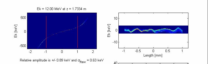
8 Figure 4 Dependence of the rms of modulation amplitude on the half bandwidth for 4 different bunch lengths. IV- Results from ASTRA simulations: ASTRA simulations were done for the LCLS injector for three types of distributions maintaining the 10- psec FWHM. The three distributions were based on a 1.0 THz frequency cutoff with input rise/fall times of 0.7 ps, 1ps and 1.5ps. Only the 0.7ps and 1.5ps cases are shown. Figures 5 and 6 show the development of the longitudinal space charge force instability along the injector beamline. It is initiated by the modulation on top of the plateau due to finite bandwidth. We show the longitudinal phase space at six locations: (1) at the gun exit, () at the entrance to L01 the first linac section, (3) 30 cm into L01, (4) m into L01, (5) at the entrance of L0, the second linac section, (6) at the end of L0. In the left hand side column, we show the longitudinal phase space. In the right hand side column, we show the longitudinal phase space after removal of the correlation up to order 5. One can see the development of the micro-bunching in that right hand side column, as it is very small compared to the total correlated energy spread. Simulations agree with the theory when one evaluates the amplitude of oscillation of the centroid of the slices along the bunch in the longitudinal phase space. We are still uncertain as of the value of the uncorrelated energy spread. We believe it is likely that numerical noise artificially increases that quantity. In the scope of our study, the comparison of figure 5 and figure 6 demonstrates that the oscillation amplitude of the slices centroid is larger for the fast rise/fall time than for longer one. It is 1.1 kev with a fast rise/fall time of 0.7 ps against 0.6 kev with a rise/fall time of 1.5 ps. A 0.7 ps rise/fall time is desired for the LCLS. It has been demonstrated that even a very small oscillation would be dramatically amplified [] in the chain of compressors
9 downstream the LCLS injector. Therefore, a laser heater has been included in the LCLS Injector beamline. End Gun Entrance L01 30cm in L01
 for varying locations, z along the beamline Right")
10 m in L01 Entrance L0 End L0 Figure 5- Evolution of longitudinal phase space along the electron beamline for a uv laser profile with rise/fall time of 0.7 ps and a 1.0 THz frequency cutoff; Left plots show the longitudinal phase space with Energy Spread in kev vs longitudinal position within the pulse (in mm) for varying locations, z along the beamline Right plots show the longitudinal phase space for the same parameters after removal of the correlation up to order 5


11 End Gun Entrance L01 30cm in L01
12 m in L01 Entrance L0 End L0 Figure 6 The same as in figure 5 except the rise/fall time is increased to 1.5 ps V- Discussion: (a) IR Bandwidth Assessment: Our analyses indicate that the uv frequency cutoff value (half bandwidth) should be at least 1.5 THz (i.e. include 14 positive sidebands). With negative sidebands also considered, this is a full bandwidth of 3 THz about the central frequency value. While 3 THz corresponds to a full uv wavelength interval of 0.65 nm at 55 nm, it also corresponds to a full ir wavelength interval of 5.9 nm at the fundamental 765 nm wavelength (where we have used equation (1) and preserved the required number of sidebands in the uv and ir cases). The appropriate methodology here is to determine first the transform limited uv pulse bandwidth (i.e. FWHM) from considerations of injector beam parameters and behavior. The ir bandwidth can then be determined from the uv case with due consideration of uv transport and details of third harmonic generation (THG) using incident ir pulses with similarly shaped temporal profiles. At ir intensity levels well below saturation, uv generation via THG is a third order process. The third order effect on the uv temporal shape at leading and trailing edges will be notable. Phase matching considerations, as determined by the crystal type and
13 thickness, limit the angular acceptance, spectral bandwidth, and temperature range for efficient THG (in addition to other factors) and can change the pulse shape. That is, the THG efficiency and pulse shaping affect each other. This is particularly true when the spectral bandwidth is significantly less than the incident ir bandwidth. These THG related details will be addressed in a Part II report and are not covered here. (b) Spectral masking and bandwidth Because we are addressing minimum bandwidth requirements, this report describes what we can expect from Fourier transform limited syntheses of laser pulse shapes (temporal profiles) by spectral masking alone. This would employ techniques similar to those described in [8 and 9] at ir wavelengths. We address the spectral requirements of the ir laser input to a spectral mask. To introduce this subject matter in a simplistic manner, we assume here, with regard to figure 1, that the ir and uv pulse envelope spectra differ only by the scaling of the central carrier frequency (which is a factor of 3 and equivalent to a THG spectral bandwidth that greatly exceeds the incident ir bandwidth). The required FWHM spectral bandwidth of the ir laser pulse can be determined from a specified cut-off value, ν c, if the functional form for the input single pulse spectrum is known. We assume a Gaussian spectrum, S for an arbitrary frequency, ν of the form: ν S = α S ( ) o exp 4. ln. (3) FWHM for which the minimum required FWHM is determined by ν c and f according to : FWHM ν c 4ln α ln f (4) where f is the relative peak amplitude (relative to the peak value at the central ir frequency) of the sideband nearest the cutoff frequency and α is a frequency independent loss factor. This comparison of spectral masking requirements with the input pulse spectrum is displayed in the figure 7. For example, in the lossless case (α =1) with f in the range to 0.01, we require that the input spectral FWHM be at least 55% to 78% (respectively) of the cutoff value ν c. This is slightly increased to the range 57% to 84% if the loss α is 0.5. Therefore, for ν c = 1.5 THz, α =0.5 and f = 0.01, the ir FWHM spectral bandwidth must exceed 1.3 THz which corresponds to.5 nm at 765 nm. Figure 7 illustrates the Gaussian ir bandwidth requirements for the case, α = 0.5 and ν c = 1.5 THz with f= It is well known that dynamic range requirements shown in figure 7 can be met with spectral masking techniques.
14 (c) Spectral masking and resolution: The precision with which transform limited ir envelopes can be synthesized by spectral masks alone must be addressed briefly Although details of the spectral masking technique is not the subject matter of this report, a few comments can be made. Weiner et al [9] have shown that an appropriate mask would be located in the midplane (Fourier plane of a focusing lens) of a conventional pulse stretcher apparatus set for zero dispersion. The stretcher design could include a diffractive grating pair, and a lens pair. δλ In this plane it is the spatial dispersion of the spectral components, that determines δx masking resolution and is given by: ( θ ) δλ d cos (5) δx F where d 1 is the grating groove density, F is the lens focal length, and θ is the diffraction angle from the grating. We suggest initially that each sideband should be spatially resolved into 10 elements. In δλ this case, we would require 10 µm element resolution for the case = nm/mm (using δx F = 00 mm, θ = 45 and 1/d = 1740 grooves per millimeter). This can be accomplished with current photolithographic methods.

15 Figure 7 : Sideband limits of a sinc spectrum imposed by a Gaussian input spectrum with a logarithmic ordinate. For the lower Gaussian curve, the FWHM bandwidth is 0.5 THz and for the upper Gaussian curve, it is 1.0 THz. The sinc spectra is for the 10 ps FWHM flattop temporal profile. (d) Comparison with Time slew variations at the Photocathode The constraint on the rise/fall time is less critical than that on the amplitude noise in the plateau region. The rise/fall time requirements being softer than anticipated means that we can accommodate slight variations in the time slew setting for the incident uv pulse which are still expected to be much less than nominal rise/fall time values. For example, a reflective uv diffraction grating can be used to establish the following two critical uv pulse conditioning requirements: (i) the transverse spatial anamorphic compression needed to obtain a circular spot on the photocathode surface and (ii) the time slew or tilted amplitude front of the uv pulse needed for time delay compensation to guarantee that the uv waveform reaches the photocathode surface simultaneously across the full spot diameter at the photocathode. For the nominal incident angle of 7 degrees (with respect to the normal of the photocathode surface) and a single uv wavelength of 55 nm (zero bandwidth in this example), a one degree variation of the incident angle on the uv launch grating corresponds to about a 130 femtosecond variation in the time slew (about % of the ideal time slew value and 13% of a 1 psec rise/fall time). This time slew error is reduced slightly if the refracted angle off the grating (which is also the incident angle approaching the photocathode) is reduced slightly (for example, from 7 to 71 degrees). Because we assume that the uv pulse is
16 imaged from the grating to the photocathode these one degree angular variations have an insignificant effect on the transform limited uv bandwidth requirements with respect to rise/fall time. VI- Conclusion: This Part I report describes minimal uv spectral bandwidth requirements for synthesis of Fourier transform limited temporal profiles (with acceptable rise/fall time and modulation amplitude on a flat plateau) to guarantee generation of electron beams of acceptably low projected emittance for successful LCLS operation. Although candidate techniques for laser pulse shaping are not evaluated here it is noted that the programmable acousto-optic dispersive technique [6,7] reshapes pulse spectra (as does spectral masking) but fundamentally generates a chirped waveform for which the FWHM spectral bandwidth by definition exceeds the transform limit associated with the temporal profile of the pulse The pulse shaping techniques of choice will be determined largely by (i) the extent to which photocathode irradiation by a chirped waveform can generate electron microbunches with a flatopped current, (ii) the ease with which temporal flattop pulse shapes with adaptive control can be generated, (iii) the impact of pulse bandwidth on ir pulse amplification as well as on THG efficiency and uv pulse shaping and (iv) bandwidth limitations imposed by the requirements of uv transport to the photocathode. Ultimately, we can anticipate that an optimal combination of pulse shaping techniques might be used to establish desired pulse shaping with adaptive features. This hybrid approach would also incorporate the shaping effects imposed by ir amplification and may afford separation of the adaptive function from passive shaping processes to some degree. In Part II, we will address the transform limited case of nonzero slope in the plateau region for which this report would serve as a useful reference. Details of the THG process will also be examined to more accurately assess minimal bandwidth and temporal shaping requirements for incident ir pulses. References: [1] Z.Huang Suppression of microbunching instability in the linac coherent light source Topics Phys. Rev. ST Accel. Beams 7, (004)- [] Juhao Wu, P. Emma, Z. Huang, C. Limborg (SLAC), M. Borland (Argonne),. "Temporal Profile Of The LCLS Photocathode Ultraviolet Drive Laser Tolerated By The Microbunching Instability".LCLS-TN-04-6, Apr pp. Presented at nd International Linear Accelerator Conference (LINAC 004), Lubeck, Germany, (16-0 Aug 004) [3] C.Limborg-Deprey et al. Computation of the Longitudinal Space Charge Effect in Photoinjectors EPAC 04 [4] C.Limborg-Deprey et al Longitudinal Space Charge Instability,
17 [5] J.A. Hoffnagle and C.M. Jefferson Design and performance of a refractive optical system that converts a Gaussian to flattop beam, Applied Optics / Vol 39. [30], 5488 (0 October 000). [6] C.Vicaro et al. Preliminary results using an acousto-optic dispersive filter for laser pulse shaping private communication [7] F. Verluise et al., Amplitude and phase control of ultrashort pulses by use of an acousto-optic programmable dispersive filter: pulse compression and shaping, Opt. Lett. 5[8], 575 (April 000). [8] A.M. Weiner, Femtosecond pulse shaping using spatial light modulators, Rev. Sci. Inst. 71[5], 199 (May 000). [9] A.M. Weiner et al., High-resolution femtosecond pulse shaping J.O.S.A. B5 [8], 1563 (August 1988).
Transverse emittance measurements on an S-band photocathode rf electron gun * Abstract
 SLAC PUB 8963 LCLS-01-06 October 2001 Transverse emittance measurements on an S-band photocathode rf electron gun * J.F. Schmerge, P.R. Bolton, J.E. Clendenin, F.-J. Decker, D.H. Dowell, S.M. Gierman,
4 FEL Physics. Technical Synopsis
 4 FEL Physics Technical Synopsis This chapter presents an introduction to the Free Electron Laser (FEL) physics and the general requirements on the electron beam parameters in order to support FEL lasing
Observation of Coherent Optical Transition Radiation in the LCLS Linac
 Observation of Coherent Optical Transition Radiation in the LCLS Linac Henrik Loos, Ron Akre, Franz-Josef Decker, Yuantao Ding, David Dowell, Paul Emma,, Sasha Gilevich, Gregory R. Hays, Philippe Hering,
FURTHER UNDERSTANDING THE LCLS INJECTOR EMITTANCE*
 Proceedings of FEL014, Basel, Switzerland FURTHER UNDERSTANDING THE LCLS INJECTOR EMITTANCE* F. Zhou, K. Bane, Y. Ding, Z. Huang, and H. Loos, SLAC, Menlo Park, CA 9405, USA Abstract Coherent optical transition
SwissFEL INJECTOR DESIGN: AN AUTOMATIC PROCEDURE
 Proceedings of FEL03, New York, NY, USA SwissFEL INJECTOR DESIGN: AN AUTOMATIC PROCEDURE S. Bettoni, M. Pedrozzi, S. Reiche, PSI, Villigen, Switzerland Abstract The first section of FEL injectors driven
Commissioning of the new Injector Laser System for the Short Pulse Project at FLASH
 Commissioning of the new Injector Laser System for the Short Pulse Project at FLASH Uni Hamburg tim.plath@desy.de 05.11.2013 Supported by BMBF under contract 05K10GU2 & FS FLASH 301 Motivation short pulses
Linac Based Photon Sources: XFELS. Coherence Properties. J. B. Hastings. Stanford Linear Accelerator Center
 Linac Based Photon Sources: XFELS Coherence Properties J. B. Hastings Stanford Linear Accelerator Center Coherent Synchrotron Radiation Coherent Synchrotron Radiation coherent power N 6 10 9 incoherent
X-Band RF Harmonic Compensation for Linear Bunch Compression in the LCLS
 SLAC-TN-5- LCLS-TN-1-1 November 1,1 X-Band RF Harmonic Compensation for Linear Bunch Compression in the LCLS Paul Emma SLAC November 1, 1 ABSTRACT An X-band th harmonic RF section is used to linearize
Femtosecond and sub-femtosecond x-ray pulses from a SASE-based free-electron laser. Abstract
 SLAC-PUB-12 Femtosecond and sub-femtosecond x-ray pulses from a SASE-based free-electron laser P. Emma, K. Bane, M. Cornacchia, Z. Huang, H. Schlarb, G. Stupakov, and D. Walz Stanford Linear Accelerator
Longitudinal Measurements at the SLAC Gun Test Facility*
 SLAC-PUB-9541 September Longitudinal Measurements at the SLAC Gun Test Facility* D. H. Dowell, P. R. Bolton, J.E. Clendenin, P. Emma, S.M. Gierman, C.G. Limborg, B.F. Murphy, J.F. Schmerge Stanford Linear
Expected properties of the radiation from VUV-FEL / femtosecond mode of operation / E.L. Saldin, E.A. Schneidmiller, M.V. Yurkov
 Expected properties of the radiation from VUV-FEL / femtosecond mode of operation / E.L. Saldin, E.A. Schneidmiller, M.V. Yurkov TESLA Collaboration Meeting, September 6-8, 2004 Experience from TTF FEL,
OPTIMUM ELECTRON DISTRIBUTIONS FOR SPACE CHARGE DOMINATED BEAMS IN PHOTOINJECTORS
 SLAC-PUB-11899 OPTIMUM ELECTRON DISTRIBUTIONS FOR SPACE CHARGE DOMINATED BEAMS IN PHOTOINJECTORS Cecile Limborg-Deprey, Paul R. Bolton Stanford Linear Accelerator Center, SLAC MS18, SLAC. 575 Sand Hill
ATTOSECOND X-RAY PULSES IN THE LCLS USING THE SLOTTED FOIL METHOD
 P. Emma et al. / Proceedings of the 24 FEL Conference, 333-338 333 ATTOSECOND X-RAY PULSES IN THE LCLS USING THE SLOTTED FOIL METHOD Abstract P. Emma, Z. Huang, SLAC, Stanford, CA 9439, USA M. Borland,
LCLS Injector Straight Ahead Spectrometer C.Limborg-Deprey Stanford Linear Accelerator Center 8 th June 2005
 LCLS Injector Straight Ahead Spectrometer C.Limborg-Deprey Stanford Linear Accelerator Center 8 th June 2005 Summary The spectrometer design was modified to allow the measurement of uncorrelated energy
OPERATING OF SXFEL IN A SINGLE STAGE HIGH GAIN HARMONIC GENERATION SCHEME
 OPERATING OF SXFEL IN A SINGLE STAGE HIGH GAIN HARMONIC GENERATION SCHEME Guanglei Wang, Weiqing Zhang, Guorong Wu, Dongxu Dai, Xueming Yang # State Key Laboratory of Molecular Reaction Dynamics, Dalian
Linac optimisation for the New Light Source
 Linac optimisation for the New Light Source NLS source requirements Electron beam requirements for seeded cascade harmonic generation LINAC optimisation (2BC vs 3 BC) CSR issues energy chirp issues jitter
Simulations of the IR/THz Options at PITZ (High-gain FEL and CTR)
") Case Study of IR/THz source for Pump-Probe Experiment at the European XFEL Simulations of the IR/THz Options at PITZ (High-gain FEL and CTR) Introduction Outline Simulations of High-gain FEL (SASE) Simulation
Case Study of IR/THz source for Pump-Probe Experiment at the European XFEL Simulations of the IR/THz Options at PITZ (High-gain FEL and CTR) Introduction Outline Simulations of High-gain FEL (SASE) Simulation
Femto-second FEL Generation with Very Low Charge at LCLS
 Femto-second FEL Generation with Very Low Charge at LCLS Yuantao Ding, For the LCLS commissioning team X-ray Science at the Femtosecond to Attosecond Frontier workshop May 18-20, 2009, UCLA SLAC-PUB-13525;
LCLS-II SCRF start-to-end simulations and global optimization as of September Abstract
 SLAC National Accelerator Lab LCLS-II TN-17-4 February 217 LCLS-II SCRF start-to-end simulations and global optimization as of September 216 G. Marcus SLAC, Menlo Park, CA 9425 J. Qiang LBNL, Berkeley,
Emittance and Quantum Efficiency Measurements from a 1.6 cell S- Band Photocathode RF Gun with Mg Cathode *
 LCLS-TN-4-3 SLAC PUB 763 September, 4 Emittance and Quantum Efficiency Measurements from a.6 cell S- Band Photocathode RF Gun with Mg Cathode * J.F. Schmerge, J.M. Castro, J.E. Clendenin, D.H. Dowell,
Linac Driven Free Electron Lasers (III)
") Linac Driven Free Electron Lasers (III) Massimo.Ferrario@lnf.infn.it SASE FEL Electron Beam Requirements: High Brightness B n ( ) 1+ K 2 2 " MIN r #$ % &B! B n 2 n K 2 minimum radiation wavelength energy
Linac Driven Free Electron Lasers (III) Massimo.Ferrario@lnf.infn.it SASE FEL Electron Beam Requirements: High Brightness B n ( ) 1+ K 2 2 " MIN r #$ % &B! B n 2 n K 2 minimum radiation wavelength energy
Simulations of the IR/THz source at PITZ (SASE FEL and CTR)
") Simulations of the IR/THz source at PITZ (SASE FEL and CTR) Introduction Outline Simulations of SASE FEL Simulations of CTR Summary Issues for Discussion Mini-Workshop on THz Option at PITZ DESY, Zeuthen
Simulations of the IR/THz source at PITZ (SASE FEL and CTR) Introduction Outline Simulations of SASE FEL Simulations of CTR Summary Issues for Discussion Mini-Workshop on THz Option at PITZ DESY, Zeuthen
Generation and characterization of ultra-short electron and x-ray x pulses
 Generation and characterization of ultra-short electron and x-ray x pulses Zhirong Huang (SLAC) Compact XFEL workshop July 19-20, 2010, Shanghai, China Ultra-bright Promise of XFELs Ultra-fast LCLS Methods
X-ray Free-electron Lasers
 X-ray Free-electron Lasers Ultra-fast Dynamic Imaging of Matter II Ischia, Italy, 4/30-5/3/ 2009 Claudio Pellegrini UCLA Department of Physics and Astronomy Outline 1. Present status of X-ray free-electron
R&D experiments at BNL to address the associated issues in the Cascading HGHG scheme
 R&D experiments at BNL to address the associated issues in the Cascading HGHG scheme Li Hua Yu for DUV-FEL Team National Synchrotron Light Source Brookhaven National Laboratory FEL2004 Outline The DUVFEL
Beam Echo Effect for Generation of Short Wavelength Radiation
 Beam Echo Effect for Generation of Short Wavelength Radiation G. Stupakov SLAC NAL, Stanford, CA 94309 31st International FEL Conference 2009 Liverpool, UK, August 23-28, 2009 1/31 Outline of the talk
ASTRA simulations of the slice longitudinal momentum spread along the beamline for PITZ
 ASTRA simulations of the slice longitudinal momentum spread along the beamline for PITZ Orlova Ksenia Lomonosov Moscow State University GSP-, Leninskie Gory, Moscow, 11999, Russian Federation Email: ks13orl@list.ru
Flexible control of femtosecond pulse duration and separation using an emittance-spoiling foil in x-ray free-electron lasers
 SLAC PUB 16312 June 2015 Flexible control of femtosecond pulse duration and separation using an emittance-spoiling foil in x-ray free-electron lasers Y. Ding 1, C. Behrens 2, R. Coffee 1, F.-J. Decker
VARIABLE GAP UNDULATOR FOR KEV FREE ELECTRON LASER AT LINAC COHERENT LIGHT SOURCE
 LCLS-TN-10-1, January, 2010 VARIABLE GAP UNDULATOR FOR 1.5-48 KEV FREE ELECTRON LASER AT LINAC COHERENT LIGHT SOURCE C. Pellegrini, UCLA, Los Angeles, CA, USA J. Wu, SLAC, Menlo Park, CA, USA We study
FEL SIMULATION AND PERFORMANCE STUDIES FOR LCLS-II
 FEL SIMULATION AND PERFORMANCE STUDIES FOR LCLS-II G. Marcus, Y. Ding, P. Emma, Z. Huang, T. Raubenheimer, L. Wang, J. Wu SLAC, Menlo Park, CA 9, USA Abstract The design and performance of the LCLS-II
Generating intense attosecond x-ray pulses using ultraviolet-laser-induced microbunching in electron beams. Abstract
 Febrary 2009 SLAC-PUB-13533 Generating intense attosecond x-ray pulses using ultraviolet-laser-induced microbunching in electron beams D. Xiang, Z. Huang and G. Stupakov SLAC National Accelerator Laboratory,
Tolerances for magnetic fields in the Gun-To-Linac region of the LCLS Injector *
 Tolerances for magnetic fields in the Gun-To-Linac region of the LCLS Injector * C.Limborg-Deprey January 10, 2006 Abstract In this technical note, we review the computations which led to the tolerances
Echo-Enabled Harmonic Generation
 Echo-Enabled Harmonic Generation G. Stupakov SLAC NAL, Stanford, CA 94309 IPAC 10, Kyoto, Japan, May 23-28, 2010 1/29 Outline of the talk Generation of microbunching in the beam using the echo effect mechanism
Beam manipulation with high energy laser in accelerator-based light sources
 Beam manipulation with high energy laser in accelerator-based light sources Ming-Chang Chou High Brightness Injector Group FEL winter school, Jan. 29 ~ Feb. 2, 2018 Outline I. Laser basic II. III. IV.
LCLS Injector Prototyping at the GTF
 LCLS Injector Prototyping at at the GTF John John Schmerge, SLAC SLAC November 3, 3, 23 23 GTF GTF Description Summary of of Previous Measurements Longitudinal Emittance Transverse Emittance Active LCLS
RF Gun Photo-Emission Model for Metal Cathodes Including Time Dependent Emission
 RF Gun Photo-Emission Model for Metal Cathodes Including Time Dependent Emission SLAC-PUB-117 February 6 (A) J. F. SCHMERGE, J. E. CLENDENIN, D. H. DOWELL, AND S. M. GIERMAN SLAC, Stanford University,
Microbunching Workshop 2010 March 24, 2010, Frascati, Italy. Zhirong Huang
 Measurements of the LCLS Laser Heater and its impact on the LCLS FEL Performance Z. Huang for the LCLS commissioning team LCLS 1 1 Outline Introduction LCLS setup and measurements Effects on FEL performance
EXPERIMENTAL STUDIES WITH SPATIAL GAUSSIAN-CUT LASER FOR THE LCLS PHOTOCATHODE GUN*
 SLAC-PUB-14571 EXPERIMETAL STUDIES WITH SPATIAL GAUSSIA-CUT LASER FOR THE LCLS PHOTOCATHODE GU* F. Zhou +, A. Brachmann, P. Emma, S. Gilevich, and Z. Huang SLAC ational Accelerator Laboratory, 575 Sand
Experimental Measurements of the ORION Photoinjector Drive Laser Oscillator Subsystem
 Experimental Measurements of the ORION Photoinjector Drive Laser Oscillator Subsystem D.T Palmer and R. Akre Laser Issues for Electron RF Photoinjectors October 23-25, 2002 Stanford Linear Accelerator
What have we learned from the LCLS injector?*
 SLAC-PUB-14644 LCLS-TN-11-4 October 19, 2011 What have we learned from the LCLS injector?* Feng Zhou and Axel Brachmann for the LCLS injector team The LCLS injector reliably delivered a high quality electron
Transverse Coherence Properties of the LCLS X-ray Beam
 LCLS-TN-06-13 Transverse Coherence Properties of the LCLS X-ray Beam S. Reiche, UCLA, Los Angeles, CA 90095, USA October 31, 2006 Abstract Self-amplifying spontaneous radiation free-electron lasers, such
LCLS Commissioning Status
 LCLS Commissioning Status Paul Emma (for the LCLS Commissioning Team) June 20, 2008 LCLS ANL LLNL UCLA FEL Principles Electrons slip behind EM wave by λ 1 per undulator period ( (λ u ) x K/γ e λ u v x
LCLS Accelerator Parameters and Tolerances for Low Charge Operations
 LCLS-TN-99-3 May 3, 1999 LCLS Accelerator Parameters and Tolerances for Low Charge Operations P. Emma SLAC 1 Introduction An option to control the X-ray FEL output power of the LCLS [1] by reducing the
Research Topics in Beam Physics Department
 Introduction Research Topics in Beam Physics Department The physics of particle beams has been a broad and vibrant research field encompassing the study of charged particle beams and their interactions.
Experimental Path to Echo-75 at NLCTA
 Experimental Path to Echo-75 at NLCTA Erik Hemsing on behalf of the ECHO group at SLAC NLCTA ICFA Workshop on Future Light Sources March 5-9, 2012 Thomas Jefferson National Accelerator Facility Motivation
Simple limits on achieving a quasi-linear magnetic compression for an FEL driver
 SLAC-PUB-14445 Simple limits on achieving a quasi-linear magnetic compression for an FEL driver Yipeng Sun (yisun@slac.stanford.edu) SLAC National Accelerator Laboratory, Menlo Park, California 94025,
Injector Experimental Progress
 Injector Experimental Progress LCLS TAC Meeting December 10-11 2001 John Schmerge for the GTF Team GTF Group John Schmerge Paul Bolton Steve Gierman Cecile Limborg Brendan Murphy Dave Dowell Leader Laser
X-band RF driven hard X-ray FELs. Yipeng Sun ICFA Workshop on Future Light Sources March 5-9, 2012
 X-band RF driven hard X-ray FELs Yipeng Sun ICFA Workshop on Future Light Sources March 5-9, 2012 Motivations & Contents Motivations Develop more compact (hopefully cheaper) FEL drivers, L S C X-band (successful
Characterization of an 800 nm SASE FEL at Saturation
 Characterization of an 800 nm SASE FEL at Saturation A.Tremaine*, P. Frigola, A. Murokh, C. Pellegrini, S. Reiche, J. Rosenzweig UCLA, Los Angeles, CA 90095 M. Babzien, I. Ben-Zvi, E. Johnson, R. Malone,
What limits the gap in a flat dechirper for an X-ray FEL?
 What limits the gap in a flat dechirper for an X-ray FEL? LCLS-II TN-13-01 12/9/2013 K.L.F. Bane and G. Stupakov December 9, 2013 LCLSII-TN-13-01 SLAC-PUB-15852 LCLS-II-TN-13-01 December 2013 What limits
PAL LINAC UPGRADE FOR A 1-3 Å XFEL
 PAL LINAC UPGRADE FOR A 1-3 Å XFEL J. S. Oh, W. Namkung, Pohang Accelerator Laboratory, POSTECH, Pohang 790-784, Korea Y. Kim, Deutsches Elektronen-Synchrotron DESY, D-603 Hamburg, Germany Abstract With
Experimental Optimization of Electron Beams for Generating THz CTR and CDR with PITZ
 Experimental Optimization of Electron Beams for Generating THz CTR and CDR with PITZ Introduction Outline Optimization of Electron Beams Calculations of CTR/CDR Pulse Energy Summary & Outlook Prach Boonpornprasert
Low slice emittance preservation during bunch compression
 Low slice emittance preservation during bunch compression S. Bettoni M. Aiba, B. Beutner, M. Pedrozzi, E. Prat, S. Reiche, T. Schietinger Outline. Introduction. Experimental studies a. Measurement procedure
Beam Dynamics and SASE Simulations for XFEL. Igor Zagorodnov DESY
 Beam Dynamics and SASE Simulations for XFEL Igor Zagorodnov 4.. DESY Beam dynamics simulations for the European XFEL Full 3D simulation method ( CPU, ~ hours) Gun LH M, M,3 E = 3 MeV E = 7 MeV E 3 = 4
Diagnostic Systems for Characterizing Electron Sources at the Photo Injector Test Facility at DESY, Zeuthen site
 1 Diagnostic Systems for Characterizing Electron Sources at the Photo Injector Test Facility at DESY, Zeuthen site Sakhorn Rimjaem (on behalf of the PITZ team) Motivation Photo Injector Test Facility at
Wakefield computations for the LCLS Injector (Part I) *
 *") LCLS-TN-05-17 Wakefield computations for the LCLS Injector (Part I) * June 13 th 005 (reedited May 007) C.Limborg-Deprey, K.Bane Abstract In this document, we report on basic wakefield computations used
LCLS-TN-05-17 Wakefield computations for the LCLS Injector (Part I) * June 13 th 005 (reedited May 007) C.Limborg-Deprey, K.Bane Abstract In this document, we report on basic wakefield computations used
Simulations of the Microbunching Instability in FEL Beam Delivery Systems
 Simulations of the Microbunching Instability in FEL Beam Delivery Systems Ilya Pogorelov Tech-X Corporation Workshop on High Average Power & High Brightness Beams UCLA, January 2009 Outline The setting:
Analysis of Slice Transverse Emittance Evolution in a Photocathode RF Gun. Abstract
 SLAC PUB 868 October 7 Analysis of Slice Transverse Emittance Evolution in a Photocathode RF Gun Z. Huang, Y. Ding Stanford Linear Accelerator Center, Stanford, CA 9439 J. Qiang Lawrence Berkeley National
SUPPLEMENTARY INFORMATION
 doi:10.1038/nature10721 Experimental Methods The experiment was performed at the AMO scientific instrument 31 at the LCLS XFEL at the SLAC National Accelerator Laboratory. The nominal electron bunch charge
Brightness and Coherence of Synchrotron Radiation and Free Electron Lasers. Zhirong Huang SLAC, Stanford University May 13, 2013
 Brightness and Coherence of Synchrotron Radiation and Free Electron Lasers Zhirong Huang SLAC, Stanford University May 13, 2013 Introduction GE synchrotron (1946) opened a new era of accelerator-based
High Energy Gain Helical Inverse Free Electron Laser Accelerator at Brookhaven National Laboratory
 High Energy Gain Helical Inverse Free Electron Laser Accelerator at Brookhaven National Laboratory J. Duris 1, L. Ho 1, R. Li 1, P. Musumeci 1, Y. Sakai 1, E. Threlkeld 1, O. Williams 1, M. Babzien 2,
An Adventure in Marrying Laser Arts and Accelerator Technologies
 An Adventure in Marrying Laser Arts and Accelerator Technologies Dao Xiang Beam Physics Dept, SLAC, Stanford University Feb-28-2012 An example sample Probe (electron) Pump (laser) Typical pump-probe experiment
Vertical Polarization Option for LCLS-II. Abstract
 SLAC National Accelerator Lab LCLS-II TN-5-8 March 5 Vertical Polarization Option for LCLS-II G. Marcus, T. Raubenheimer SLAC, Menlo Park, CA 95 G. Penn LBNL, Berkeley, CA 97 Abstract Vertically polarized
MOGA Optimization of LCLS2 Linac
 SLAC-PUB-15998 MOGA Optimization of LCLS2 Linac Lanfa Wang, Paul Emma and Tor O. Raubenheimer SLAC National Accelerator Laboratory June 2014 Presented at the FEL 2014 Basel, Switzerland, 25-29 August 2014
VELA/CLARA as Advanced Accelerator Studies Test-bed at Daresbury Lab.
 VELA/CLARA as Advanced Accelerator Studies Test-bed at Daresbury Lab. Yuri Saveliev on behalf of VELA and CLARA teams STFC, ASTeC, Cockcroft Institute Daresbury Lab., UK Outline VELA (Versatile Electron
Two-Stage Chirped-Beam SASE-FEL for High Power Femtosecond X-Ray Pulse Generation
 Two-Stage Chirped-Beam SASE-FEL for High ower Femtosecond X-Ray ulse Generation C. Schroeder*, J. Arthur^,. Emma^, S. Reiche*, and C. ellegrini* ^ Stanford Linear Accelerator Center * UCLA 12-10-2001 LCLS-TAC
OPTIMIZATION OF COMPENSATION CHICANES IN THE LCLS-II BEAM DELIVERY SYSTEM
 OPTIMIZATION OF COMPENSATION CHICANES IN THE LCLS-II BEAM DELIVERY SYSTEM LCLS-II TN-15-41 11/23/2015 J. Qiang, M. Venturini November 23, 2015 LCLSII-TN-15-41 1 Introduction L C L S - I I T E C H N I C
MaRIE. MaRIE X-Ray Free-Electron Laser Pre-Conceptual Design
 Operated by Los Alamos National Security, LLC, for the U.S. Department of Energy MaRIE (Matter-Radiation Interactions in Extremes) MaRIE X-Ray Free-Electron Laser Pre-Conceptual Design B. Carlsten, C.
FLASH/DESY, Hamburg. Jörg Rossbach University of Hamburg & DESY, Germany - For the FLASH Team -
 First Lasing below 7nm Wavelength at FLASH/DESY, Hamburg Jörg Rossbach University of Hamburg & DESY, Germany - For the FLASH Team - email: joerg.rossbach@desy.de FLASH: The first FEL user facility for
Free-electron laser SACLA and its basic. Yuji Otake, on behalf of the members of XFEL R&D division RIKEN SPring-8 Center
 Free-electron laser SACLA and its basic Yuji Otake, on behalf of the members of XFEL R&D division RIKEN SPring-8 Center Light and Its Wavelength, Sizes of Material Virus Mosquito Protein Bacteria Atom
Free Electron Laser. Project report: Synchrotron radiation. Sadaf Jamil Rana
 Free Electron Laser Project report: Synchrotron radiation By Sadaf Jamil Rana History of Free-Electron Laser (FEL) The FEL is the result of many years of theoretical and experimental work on the generation
Summary of COTR Effects.
 Summary of COTR Effects. Stephan Wesch Deutsches Elektronen-Synchrotron, Hamburg 10 th European Workshop on Beam Diagnostics and Instrumentation for Particle Accelerators S. Wesch (DESY) Summary of COTR
NON LINEAR PULSE EVOLUTION IN SEEDED AND CASCADED FELS
 NON LINEAR PULSE EVOLUTION IN SEEDED AND CASCADED FELS L. Giannessi, S. Spampinati, ENEA C.R., Frascati, Italy P. Musumeci, INFN & Dipartimento di Fisica, Università di Roma La Sapienza, Roma, Italy Abstract
Femtosecond X-ray Pulse Temporal Characterization in Free-Electron Lasers Using a Transverse Deflector. Abstract
 SLAC PUB 14534 September 2011 Femtosecond X-ray Pulse Temporal Characterization in Free-Electron Lasers Using a Transverse Deflector Y. Ding 1, C. Behrens 2, P. Emma 1, J. Frisch 1, Z. Huang 1, H. Loos
Start-to-End Simulations
 AKBP 9.3 Case Study for 100 µm SASE FEL Based on PITZ Accelerator for Pump-Probe Experiment at the European XFEL Start-to-End Simulations Outline Introduction Beam Optimization Beam Transport Simulation
Harmonic Lasing Self-Seeded FEL
 Harmonic Lasing Self-Seeded FEL E. Schneidmiller and M. Yurkov FEL seminar, DESY Hamburg June 21, 2016 In a planar undulator (K ~ 1 or K >1) the odd harmonics can be radiated on-axis (widely used in SR
RF Design for the Linac Coherent Light Source (LCLS) Injector *
 Injector *") SLAC PUB 1767 September, 24 RF Design for the Linac Coherent Light Source (LCLS) Injector * D.H. Dowell, L. Bentson, R.F. Boyce, S.M. Gierman, J. Hodgson, Z. Li, C. Limborg-Deprey, J.F. Schmerge, L. Xiao,
SLAC PUB 1767 September, 24 RF Design for the Linac Coherent Light Source (LCLS) Injector * D.H. Dowell, L. Bentson, R.F. Boyce, S.M. Gierman, J. Hodgson, Z. Li, C. Limborg-Deprey, J.F. Schmerge, L. Xiao,
Alignment requirement for the SRF cavities of the LCLS-II injector LCLSII-TN /16/2014
 Alignment requirement for the SRF cavities of the LCLS-II injector LCLS-II TN-14-16 12/16/2014 R. K. Li, C. Papadopoulos, T. O. Raubenheimer, J. F. Schmerge, and F. Zhou December 16, 2014 LCLSII-TN-14-16
LOLA: Past, present and future operation
 LOLA: Past, present and future operation FLASH Seminar 1/2/29 Christopher Gerth, DESY 8/5/29 FLASH Seminar Christopher Gerth 1 Outline Past Present Future 8/5/29 FLASH Seminar Christopher Gerth 2 Past
Parameter selection and longitudinal phase space simulation for a single stage X-band FEL driver at 250 MeV
 Parameter selection and longitudinal phase space simulation for a single stage X-band FEL driver at 25 MeV Yipeng Sun and Tor Raubenheimer, Juhao Wu SLAC, Stanford, CA 9425, USA Hard x-ray Free electron
Dark Current at Injector. Jang-Hui Han 27 November 2006 XFEL Beam Dynamics Meeting
 Dark Current at Injector Jang-Hui Han 27 November 2006 XFEL Beam Dynamics Meeting Considerations for the guns Ultra-low slice emittance of electron beams higher gradient at the gun cavity solenoid field
HIGH-POWER THIRD-HARMONIC FLAT LASER PULSE GENERATION. Abstract
 SPARC-LS-07/001 23 May 2007 HIGH-POWER THIRD-HARMONIC FLAT LASER PULSE GENERATION C. Vicario (INFN/LNF), M. Petrarca. (INFN/Roma1), S. Cialdi (INFN/Milano) P. Musumeci (UCLA). Abstract The generation of
Some Sample Calculations for the Far Field Harmonic Power and Angular Pattern in LCLS-1 and LCLS-2
 Some Sample Calculations for the Far Field Harmonic Power and Angular Pattern in LCLS-1 and LCLS-2 W.M. Fawley February 2013 SLAC-PUB-15359 ABSTRACT Calculations with the GINGER FEL simulation code are
Accelerator Physics Issues of ERL Prototype
 Accelerator Physics Issues of ERL Prototype Ivan Bazarov, Geoffrey Krafft Cornell University TJNAF ERL site visit (Mar 7-8, ) Part I (Bazarov). Optics. Space Charge Emittance Compensation in the Injector
Short Pulse, Low charge Operation of the LCLS. Josef Frisch for the LCLS Commissioning Team
 Short Pulse, Low charge Operation of the LCLS Josef Frisch for the LCLS Commissioning Team 1 Normal LCLS Parameters First Lasing in April 10, 2009 Beam to AMO experiment August 18 2009. Expect first user
Coherence Requirements for Various Seeding Schemes
 Coherence Requirements for Various Seeding Schemes G. Penn 2.5 1 1 2. 1 1 sase 4 high current 4 low current SSSFEL12 Trieste 1 December 212 # photons / mev 1.5 1 1 1. 1 1 5. 1 9 1238.5 1239 1239.5 124
Simulations for photoinjectors C.Limborg
 Simulations for photoinjectors C.Limborg 1- GTF Simulations Parmela modeling improvements Comparison to experimental results: 2ps & 4ps Sensitivity study Plans for future simulations 2- LCLS Injector Simulations
Deutsches Elektronen-Synchrotron (DESY), Notkestrasse 85, D Hamburg, space charge eld is found to be the main eect driving the instability.
, Notkestrasse 85, D Hamburg, space charge eld is found to be the main eect driving the instability.") TESLA-FEL-2003-02 May 2003 Longitudinal Space Charge Driven Microbunching Instability in TTF2 linac E.L. Saldin a, E.A. Schneidmiller a, M.V. Yurkov b a Deutsches Elektronen-Synchrotron (DESY), Notkestrasse
TESLA-FEL-2003-02 May 2003 Longitudinal Space Charge Driven Microbunching Instability in TTF2 linac E.L. Saldin a, E.A. Schneidmiller a, M.V. Yurkov b a Deutsches Elektronen-Synchrotron (DESY), Notkestrasse
Experimental Observation of Energy Modulation in Electron Beams Passing. Through Terahertz Dielectric Wakefield Structures
 Experimental Observation of Energy Modulation in Electron Beams Passing Through Terahertz Dielectric Wakefield Structures S. Antipov 1,3, C. Jing 1,3, M. Fedurin 2, W. Gai 3, A. Kanareykin 1, K. Kusche
START-TO-END SIMULATIONS FOR IR/THZ UNDULATOR RADIATION AT PITZ
 Proceedings of FEL2014, Basel, Switzerland MOP055 START-TO-END SIMULATIONS FOR IR/THZ UNDULATOR RADIATION AT PITZ P. Boonpornprasert, M. Khojoyan, M. Krasilnikov, F. Stephan, DESY, Zeuthen, Germany B.
Photoinjector design for the LCLS
 SLAC-PUB-8962 LCLS-TN-01-05 Revised November 2001 Photoinjector design for the LCLS P.R. Bolton a, J.E. Clendenin a, D.H. Dowell a, M. Ferrario b, A.S. Fisher a, S.M. Gierman a, R.E. Kirby a, P. Krejcik
CONCEPTUAL STUDY OF A SELF-SEEDING SCHEME AT FLASH2
 CONCEPTUAL STUDY OF A SELF-SEEDING SCHEME AT FLASH2 T. Plath, L. L. Lazzarino, Universität Hamburg, Hamburg, Germany K. E. Hacker, T.U. Dortmund, Dortmund, Germany Abstract We present a conceptual study
THE LASER HEATER SYSTEM OF SWISSFEL
 THE LASER HEATER SYSTEM OF SWISSFEL M. Pedrozzi, M. Calvi, R. Ischebeck, S. Reiche, C. Vicario, PSI, Villigen, Switzerland B. D. Fell, N. Thompson, STFC/DL/ASTeC, Daresbury, UK Short wavelength FELs are
Beam Dynamics. Gennady Stupakov. DOE High Energy Physics Review June 2-4, 2004
 Beam Dynamics Gennady Stupakov DOE High Energy Physics Review June 2-4, 2004 Beam Dynamics Research in ARDA Broad expertise in many areas: lattice design, collective effects, electron cloud, beam-beam
Microbunching Instability due to Bunch Compression
 Sumitted to ICFA Beam Dynamics Newsletter SLAC-PUB-11597 December, 25 Microbunching Instability due to Bunch Compression Zhirong Huang, Juhao Wu (SLAC) Timur Shaftan (BNL) mail to: zrh@slac.stanford.edu
X-Ray Diagnostics Commissioning at the LCLS
 X-Ray Diagnostics Commissioning at the LCLS - Selected Studies - J. Welch, SLAC National Accelerator Laboratory Aug. 3-27, 2010 Commissioning Studies Microbunching Instability Laser Heater tune-up Gas
Short Wavelength SASE FELs: Experiments vs. Theory. Jörg Rossbach University of Hamburg & DESY
 Short Wavelength SASE FELs: Experiments vs. Theory Jörg Rossbach University of Hamburg & DESY Contents INPUT (electrons) OUTPUT (photons) Momentum Momentum spread/chirp Slice emittance/ phase space distribution
Undulator radiation from electrons randomly distributed in a bunch
 Undulator radiation from electrons randomly distributed in a bunch Normally z el >> N u 1 Chaotic light Spectral property is the same as that of a single electron /=1/N u Temporal phase space area z ~(/
Excitements and Challenges for Future Light Sources Based on X-Ray FELs
 Excitements and Challenges for Future Light Sources Based on X-Ray FELs 26th ADVANCED ICFA BEAM DYNAMICS WORKSHOP ON NANOMETRE-SIZE COLLIDING BEAMS Kwang-Je Kim Argonne National Laboratory and The University
First operation of a Harmonic Lasing Self-Seeded FEL
 First operation of a Harmonic Lasing Self-Seeded FEL E. Schneidmiller and M. Yurkov ICFA workshop, Arcidosso, Italy, 22.09.2017 Outline Harmonic lasing Harmonic lasing self-seeded (HLSS) FEL Experiments