Juliane Rönsch Hamburg University. Investigations of the longitudinal phase space at a photo injector for the X-FEL
|
|
|
- Joy Cook
- 5 years ago
- Views:
Transcription
1 Juliane Rönsch Hamburg University Investigations of the longitudinal phase space at a photo injector for the X-FEL Juliane Rönsch 1/15/28 1
2 Contents Introduction PITZ Longitudinal phase space of a photoinjector Devices of longitudinal phase space measurement at PITZ Measurements and simulations of longitudinal phase space at PITZ Summery and outlook 2
3 Contents Introduction PITZ Longitudinal phase space of a photoinjector Devices of longitudinal phase space measurement at PITZ Measurements and simulations of longitudinal phase space at PITZ Summery and outlook 2
4 Introduction 3
5 Introduction gun: - beam of a few MeV -> space charge forces play a major role on emittance growth -> the initial electron bunch length: 2ps -> peak current: about 5 A bunch compressor: - energy is high enough to neglect space charge forces - bunch compression increases peak current - optimum compression: only for a linear long. phase space -> 3rd harmonic -> knowledge of longitudinal phase space is of particular interest 3


6 Introduction gun: - beam of a few MeV -> space charge forces play a major role on emittance growth -> the initial electron bunch length: 2ps -> peak current: about 5 A bunch compressor: - energy is high enough to neglect space charge forces - bunch compression increases peak current - optimum compression: only for a linear long. phase space -> 3rd harmonic -> knowledge of longitudinal phase space is of particular interest 3
7 Contents Introduction PITZ Longitudinal phase space of a photoinjector Devices of longitudinal phase space measurement at PITZ Measurements and simulations of longitudinal phase space at PITZ Summery and outlook
8 PITZ 4
9 PITZ 4


10 PITZ 4
11 PITZ PITZ1 setup PITZ2 setup 5
12 1 Setup of PITZ GUN cavity BOOSTER cavity 6
13 Setup of PITZ charge measurement: faraday cup ICT GUN cavity BOOSTER cavity 7
14 Setup of PITZ beam size measurement: view screens combined with CCD Cameras wire scanners BPMs GUN cavity BOOSTER cavity 8
15 Setup of PITZ beam size measurement: view screens combined with CCD Cameras wire scanners BPMs GUN cavity transverse emittance measurement: EMSYs: slit scan method tomography module BOOSTER cavity 8
16 Setup of PITZ slice emittance measurement: RF-deflector and tomography module dipole, slit and quadrupole quadrupole, aerogel and streak camera GUN cavity BOOSTER cavity 9

17 Setup of PITZ longitudinal phase space measurement: Beam momentum distribution longitudinal distribution longitudinal phase space GUN cavity BOOSTER cavity 1
18 Contents Introduction PITZ Longitudinal phase space of a photoinjector Devices of longitudinal phase space measurement at PITZ Measurements and simulations of longitudinal phase space at PITZ Summery and outlook


19 Longitudinal phase space of a photoinjector head tail 1 nc 4 MeV/m.5m after the cathode laser: long.: flat-top FWHM : 2 ps risetime : 7 ps transv.: flat-top Ø : 2 mm projections of longitudinal phase space: momentum distribution longitudinal distribution area of longitudinal phase space: emittance εz εz = <( pz)2> <( z)2> - < pz z>2 11
20 Contents Introduction PITZ Longitudinal phase space of a photoinjector Devices of longitudinal phase space measurement at PITZ Measurements and simulations of longitudinal phase space at PITZ Summery and outlook
21 Devices of longitudinal phase space measurement at PITZ Beam momentum distribution: dipole magnet and a view screen Bunch length: - aerogel or OTR as radiators and a streak camera - RF deflector Longitudinal phase space: - dipole magnet, radiator and streak camera - RF deflector and dipole magnet 12
22 measurement of longitudinal distribution using streak camera empty tube tilted quartz TVcamera mirror OTR YAG eaerogel mirror 3 m optical transmission line to streak camera 13
23 measurement of longitudinal distribution using streak camera e- Silica aerogel n =
24 measurement of longitudinal distribution using streak camera e- Silica aerogel n = Cherenkov radiator electron bunch is transformed into a light pulse with approximately the same temporal distribution by the Cherenkov effect 14
25 measurement of longitudinal distribution using streak camera Silica aerogel n = Cherenkov radiator electron bunch is transformed into a light pulse with approximately the same temporal distribution by the Cherenkov effect 14
26 measurement of longitudinal distribution using streak camera Silica aerogel n = Cherenkov radiator electron bunch is transformed into a light pulse with approximately the same temporal distribution by the Cherenkov effect 14
27 measurement of longitudinal distribution using streak camera electron bunch is transformed into a light pulse with approximately the same temporal distribution by the Cherenkov effect Silica aerogel n = Cherenkov radiator 14
28 measurement of longitudinal distribution using streak camera e- Silica aerogel n = Cherenkov radiator electron bunch is transformed into a light pulse with approximately the same temporal distribution by the Cherenkov effect light transport streak camera measurement 14
29 measurement of longitudinal distribution using streak camera e- electron bunch is transformed into a light pulse with approximately the same temporal distribution by the Cherenkov effect light transport streak camera measurement advantage compared to RF-deflector: measurement at several positions along the beamline disadvantage compared to RF-deflector: poor resolution Silica aerogel n = Cherenkov radiator 14
30 measurement of longitudinal distribution using streak camera 15
31 measurement of longitudinal distribution using streak camera The amount of light produced by silica aerogel is several order of magnitude higher than the the one of an OTRscreen. 15

32 measurement of longitudinal distribution using streak camera The amount of light produced by silica aerogel is several order of magnitude higher than the the one of an OTRscreen. 15
33 momentum measurement DISP1.Scr1 DISP2.Scr1 DISP3.Scr1 16
34 momentum measurement DISP1.Scr1 y y' x x' t p/p DISP2.Scr1 R11 R12 R21 R22 R51 R52 = R33 R34 R43 R44 1 R16 R26 R56 1 DISP3.Scr1 y y' x x' t p/p 16
35 momentum measurement DISP1.Scr1 DISP2.Scr1 DISP3.Scr1 p = e / α Bdipole (l) dl pc = e Bdipole leff / α p = pc y / R16 R16 = (leff / α + LDA tanβout) (1-cosα ) + LDA sinα. LDA y y' x x' t p/p R11 R12 R21 R22 R51 R52 = R33 R34 R43 R44 1 R16 R26 R56 1 y y' x x' t p/p 16
36 momentum measurement DISP1.Scr1 DISP2.Scr1 HEDA1 deflection angle α βin βout r (mm) LDA (mm) leff (mm) gap width (mm) Disp1.Scr1 6 Disp2.Scr1/2 18 Disp3.Scr1 6 spare dipole > to be defined > 25 ~15 -> >~ >~16 2 -> / to be defined to be defined to be defined to be defined 43 2 ~
37 Measurement of longitudinal phase space YAGscreen light pulse radiator equivalent to temporal distribution of the electron bunch (produced by a radiator) spatial p1 p2 distribution of the momenta in the p1 > p2 bunch of mea of lo surem pha ngitu ent se s dina pac l e ent rem th asu ng me ch le bun radiator / YAGscreen dipole electron bunch p= e α Bdipole (l) dl momentum measurement CCD-camera light distribution equivalent to temporal and spatial distribution of the electron bunch behind the dipole (produced by a radiator) with optical transmission line transported to streak camera 18
38 spectrometer magnet HEDA1 L1 L2 Booster Q2 S2 Gun L2 D S1 Q1 Dump Slit deflecting angle: 18 deflecting radius: 3 mm Leff = 1/B Bx dz Leff = mm geometrical length: Lgeom = mm 19
39 spectrometer magnet HEDA1 L1 L2 S2 1 L1 +L2 M S= 1 1 Gun Booster Q2 L2 D S1 Q1 Dump Slit 1 L 1 L2 2ρ M D= 1 1 deflecting angle: 18 deflecting radius: 3 mm Leff = 1/B Bx dz Leff = mm geometrical length: Lgeom = mm 19
40 spectrometer magnet HEDA1 L1 L2 S2 1 L1 +L2 M S= 1 1 Gun Booster Q2 L2 D vertical distribution y = R11 y + R12 y' + R16 p /p S1 Q1 Dump Slit 1 L 1 L2 2ρ M D= 1 1 R16 dp /p R11 y + R12 y' 2
41 spectrometer magnet HEDA1 L1 L2 without focussing S2 1 L1 +L2 M S= 1 1 Gun Booster Q2 L2 D vertical distribution y = R11 y + R12 y' + R16 p /p R16 dp /p R11 y + R12 y' S1 Q1 Dump Slit 1 L 1 L2 2ρ M D= 1 1 focus on S2 21
42 spectrometer magnet HEDA1 L1 L2 without focussing S2 1 L1 +L2 M S= 1 1 Gun Booster Q2 L2 D vertical distribution y = R11 y + R12 y' + R16 p /p R16 dp /p R11 y + R12 y' correction by deconvolution S1 Q1 Dump Slit 1 L 1 L2 2ρ M D= 1 1 focus on S2 21
43 spectrometer magnet HEDA1 L1 L2 S2 1 L1 +L2 M S= 1 1 Gun Booster Q2 L2 D vertical distribution y = R11 y + R12 y' + R16 p /p S1 Q1 Dump Slit 1 L 1 L2 2ρ M D= 1 1 R16 dp /p R11 y + R12 y' temporal distribution: t = R51 y + R52 y' + t + R56 p /p correction by deconvolution 22
44 spectrometer magnet HEDA1 L1 L2 S2 1 L1 +L2 M S= 1 1 Gun Booster Q2 L2 D vertical distribution y = R11 y + R12 y' + R16 p /p S1 Q1 Dump Slit 1 L 1 L2 2ρ on S2 M D=focus 1 1 R16 dp /p R11 y + R12 y' temporal distribution: t = R51 y + R52 y' + t + R56 p /p correction by deconvolution 23
45 spectrometer magnet without HEDA1 focussing L1 L2 S2 1 L1 +L2 M S= 1 1 Gun Booster Q2 L2 D vertical distribution y = R11 y + R12 y' + R16 p /p S1 Q1 Dump Slit 1 L 1 L2 2ρ on S2 M D=focus 1 1 R16 dp /p R11 y + R12 y' temporal distribution: t = R51 y + R52 y' + t + R56 p /p correction by deconvolution 23
46 spectrometer magnet HEDA1 L1 L2 S2 1 L1 +L2 M S= 1 1 Gun Booster Q2 L2 D vertical distribution S1 Q1 Dump Slit y = R11 y + R12 y' + R16 p /p 1 L 1 L2 2ρ M D= 1 1 R16 dp /p R11 y + R12 y' temporal distribution: t = R51 y + R52 y' + t + R56 p /p correction by deconvolution correction by shearing the image 24
47 spectrometer magnet HEDA1 L1 L2 Booster Q2 S2 Gun L2 D S1 Q1 Dump Slit Silica aerogel n = 1.5 thickness: 2 mm Silica aerogel n = 1.5 thickness: 5 mm 25
48 optical transmission line 26
49 optical transmission line the optical system is the major limitation of resolution, a system consisting of reflective optics is under development 27
50 Influence of the streak camera (C568) resolution is limited by: streak camera slit width and space charge slit width of 1 m: t = 1.75 ps correction: deconvolution (signal without RF-field) RF and laser jitter: 1 pulses: t =.99 ps diff. momentum of photo electrons for diff. wavelength with 1 nm: t =.16 ps, without filter: t =.55 ps from Hamamatsu home page, C568 series ( 28
 Background of the streak")

51 Influence of the streak camera (C568) Background of the streak camera with closed shutter curvature-effect horizontal sensitivity 29
52 Contents Introduction PITZ Longitudinal phase space of a photoinjector Devices of longitudinal phase space measurement at PITZ Measurements and simulations of longitudinal phase space at PITZ Summery and outlook
53 momentum measurement Gradient: ~4MV/m mean momenta are similar for different charge highest mean momentum: 4.8 MeV/c lunch phase: 35 3

54 momentum measurement Gradient: ~4MV/m mean momenta are similar for different charge highest mean momentum: 4.8 MeV/c lunch phase: 35 3


55 momentum gain 31

56 influence of charge momentum measurement Gradient: ~4MV/m mean momenta are similar for different charge highest mean momentum: 4.8 MeV/c lunch phase: 35 minimum momentum spread: 3 pc: 5 kev/c at lunch phase: 35 1 nc: 13 kev/c at lunch phase: 3 for high phase the momentum distribution is cut by the screen at 1nC space charge effects increase momentum spread at 3 pc phase of maximum momentum gain is equal to phase of minimum momentum spread -> space charge forces small 32
57 longitudinal phase space simulations 33


58 longitudinal phase space simulations 4MV/m rise time = 7ps 6MV/m rise time = 7ps 6MV/m rise time = 2ps 33


59 longitudinal phase space simulations 4MV/m rise time = 7ps 6MV/m rise time = 7ps 6MV/m rise time = 2ps 33


60 longitudinal phase space simulations 4MV/m rise time = 7ps 6MV/m rise time = 7ps 6MV/m rise time = 2ps 33


61 longitudinal phase space simulations 4MV/m rise time = 7ps 6MV/m rise time = 7ps 6MV/m rise time = 2ps 33


62 longitudinal phase space simulations 4MV/m rise time = 7ps 6MV/m rise time = 7ps 6MV/m rise time = 2ps 33


63 longitudinal phase space simulations 4MV/m rise time = 7ps 6MV/m rise time = 7ps 6MV/m rise time = 2ps 33


64 longitudinal phase space simulations 4MV/m rise time = 7ps 6MV/m rise time = 7ps 6MV/m rise time = 2ps 33


65 longitudinal phase space simulations 4MV/m rise time = 7ps 6MV/m rise time = 7ps 6MV/m rise time = 2ps 33


66 longitudinal phase space simulations 4MV/m rise time = 7ps 6MV/m rise time = 7ps 6MV/m rise time = 2ps 33


67 longitudinal phase space simulations 4MV/m rise time = 7ps 6MV/m rise time = 7ps 6MV/m rise time = 2ps 33


68 longitudinal phase space simulations 4MV/m rise time = 7ps 6MV/m rise time = 7ps 6MV/m rise time = 2ps 33


69 longitudinal phase space simulations 4MV/m rise time = 7ps 6MV/m rise time = 7ps 6MV/m rise time = 2ps 33


70 longitudinal phase space simulations 4MV/m rise time = 7ps 6MV/m rise time = 7ps 6MV/m rise time = 2ps 33


71 longitudinal phase space simulations 4MV/m rise time = 7ps 6MV/m rise time = 7ps 6MV/m rise time = 2ps 33


72 longitudinal phase space simulations 4MV/m rise time = 7ps 6MV/m rise time = 7ps 6MV/m rise time = 2ps 33


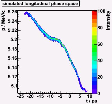
73 longitudinal phase space simulations Beam density distribution for: 1 nc transv. laser diameter = 2mm Flat-top laser opt. gun phase 4MV/m rise time = 7ps 6MV/m rise time = 7ps 6MV/m rise time = 2ps 33


74 simulations for optimum phase, 1 nc, flat-top laser distribution at different positions (~4MV/m).31 m.66m 1.1m 1.36m 1.71m 2.5 m 2.4m 2.75m 3.1m 3.45m 34


75 simulations for optimum phase, 3 pc, flat-top laser distribution at different positions (~4MV/m).31 m.66m 1.1m 1.36m 1.71m 2.5 m 2.4m 2.75m 3.1m 3.45m 35


76 optimum phase, 3 pc, flat-top laser distribution ASTRA streak YAG SS DA ASTRA for optimum phase accelerating field reaches its maximum during emission time this means electrons emitted in the middle of the bunch receive the highest acceleration due to the field due to space charge effects the particles in the beginning of the bunch become accelerated and the ones in the end decelerated 36


77 ASTRA streak YAG ASTRA SS DA ASTRA streak YAG ASTRA SS DA ASTRA streak YAG ASTRA SS DA ASTRA streak YAG ASTRA SS DA ASTRA streak YAG ASTRA SS DA 37
78 ASTRA streak YAG ASTRA SS DA optimum phase, 1 nc, flat-top laser distribution measured FWHM / ps StSe: /- 1.3; DA: /- 3.3 long. emittance / π kev mm /-6.8 momentum / MeV /-.6 momentum spread / kev 46. +/- 5.1 Astra 25 26,6 5,19 42,2 38


79 momentum measurement after the booster cavity 39
80 bunch length after the booster cavity Bunch length and arrival time as a function of the booster phase Beam density distribution for: 8 pc transv. laser diameter = 1.5mm Flat-top laser opt. Gun phase 15.9 MeV/c 4
81 momentum measurement after the booster cavity Beam density distribution for: 1 nc transv. laser diameter = 2mm Flat-top laser opt. Gun phase Beam density distribution for: 1 nc transv. laser diameter = 1.5mm Flat-top laser opt. gun and booster phase 41
82 momentum measurement after the booster cavity Beam density distribution for: 1 nc transv. laser diameter = 1.5mm Flat-top laser opt. gun and booster phase 56 peak current (A) laser diameter (mm) 41
83 Summery and outlook The PITZ setup and its diagnostics was presented A method to measure the longitudinal phase space and its projection used at PITZ was presented Resolution of this method was analysed, the major limitation of the temporal resolution is the optical transmission, an replacement by reflective optics is ongoing Examples of longitudinal phase space, bunch length and momentum measurement at PITZ and simulations were presented 42
84 Thanks for your attention
Investigations on the electron bunch distribution in the longitudinal phase space at a laser driven RF-electron source for the European X-FEL
 Juliane Rönsch Universität Hamburg / DESY Investigations on the electron bunch distribution in the longitudinal phase space at a laser driven RF-electron source for the European X-FEL 5/27/2009 1 Contents
RF-Gun Experience at PITZ - Longitudinal Phase Space
 - Collaboration meeting 9th of October 2006 Hamburg University Juliane Rönsch 1 Motivation special device to measure the longitudinal phase space at low momentum typical high energy diagnostics can not
Diagnostic Systems for Characterizing Electron Sources at the Photo Injector Test Facility at DESY, Zeuthen site
 1 Diagnostic Systems for Characterizing Electron Sources at the Photo Injector Test Facility at DESY, Zeuthen site Sakhorn Rimjaem (on behalf of the PITZ team) Motivation Photo Injector Test Facility at
Time resolved transverse and longitudinal phase space measurements at the high brightness photo injector PITZ
 Time resolved transverse and longitudinal phase space measurements at the high brightness photo injector PITZ 1. Motivation 2. Transverse deflecting structure 3. Longitudinal phase space tomography 4.
Introduction to the benchmark problem
 Introduction to the benchmark problem M. Krasilnikov (DESY) Working group 4: Low emittance electron guns 37th ICFA Beam Dynamics Workshop Future Light Sources 15 19 May 6 DESY, Hamburg, Germany Outline
Simulations of the IR/THz Options at PITZ (High-gain FEL and CTR)
") Case Study of IR/THz source for Pump-Probe Experiment at the European XFEL Simulations of the IR/THz Options at PITZ (High-gain FEL and CTR) Introduction Outline Simulations of High-gain FEL (SASE) Simulation
Case Study of IR/THz source for Pump-Probe Experiment at the European XFEL Simulations of the IR/THz Options at PITZ (High-gain FEL and CTR) Introduction Outline Simulations of High-gain FEL (SASE) Simulation
Low energy high brilliance beam characterization
 Low energy high brilliance beam characterization J. Bähr, DESY, Zeuthen, Germany Abstract Low energy high brilliance beam characterization plays an important role for electron sources and injectors of
ASTRA simulations of the slice longitudinal momentum spread along the beamline for PITZ
 ASTRA simulations of the slice longitudinal momentum spread along the beamline for PITZ Orlova Ksenia Lomonosov Moscow State University GSP-, Leninskie Gory, Moscow, 11999, Russian Federation Email: ks13orl@list.ru
Experimental Optimization of Electron Beams for Generating THz CTR and CDR with PITZ
 Experimental Optimization of Electron Beams for Generating THz CTR and CDR with PITZ Introduction Outline Optimization of Electron Beams Calculations of CTR/CDR Pulse Energy Summary & Outlook Prach Boonpornprasert
SRF GUN CHARACTERIZATION - PHASE SPACE AND DARK CURRENT MEASUREMENTS AT ELBE*
 SRF GUN CHARACTERIZATION - PHASE SPACE AND DARK CURRENT MEASUREMENTS AT ELBE* E. Panofski #, A. Jankowiak, T. Kamps, Helmholtz-Zentrum Berlin, Berlin, Germany P.N. Lu, J. Teichert, Helmholtz-Zentrum Dresden-Rossendorf,
Projected and slice emittance measurements using multi-quadrupole scan and streak readout at PITZ
 Projected and slice emittance measurements using multi-quadrupole scan and streak readout at PITZ R. Spesyvtsev, DESY, Zeuthen site September 14, 29 1 Introduction The Photo Injector Test Facility at DESY,
Simulations of the IR/THz source at PITZ (SASE FEL and CTR)
") Simulations of the IR/THz source at PITZ (SASE FEL and CTR) Introduction Outline Simulations of SASE FEL Simulations of CTR Summary Issues for Discussion Mini-Workshop on THz Option at PITZ DESY, Zeuthen
Simulations of the IR/THz source at PITZ (SASE FEL and CTR) Introduction Outline Simulations of SASE FEL Simulations of CTR Summary Issues for Discussion Mini-Workshop on THz Option at PITZ DESY, Zeuthen
Diagnostic Systems for High Brightness Electron Injectors
 Diagnostic Systems for High Brightness Electron Injectors Henrik Loos 48 th ICFA Advanced Beam Dynamics Workshop on Future Light Sources SLAC 2010 1 1 Henrik Loos LCLS Injector Injector Diagnostics Characterize
LOLA: Past, present and future operation
 LOLA: Past, present and future operation FLASH Seminar 1/2/29 Christopher Gerth, DESY 8/5/29 FLASH Seminar Christopher Gerth 1 Outline Past Present Future 8/5/29 FLASH Seminar Christopher Gerth 2 Past
Modeling of the secondary electron emission in rf photocathode guns
 Modeling of the secondary electron emission in rf photocathode guns J.-H. Han, DESY Zeuthen 8 June 2004 Joint Uni. Hamburg and DESY Accelerator Physics Seminar Contents 1. Necessity of secondary electron
Low slice emittance preservation during bunch compression
 Low slice emittance preservation during bunch compression S. Bettoni M. Aiba, B. Beutner, M. Pedrozzi, E. Prat, S. Reiche, T. Schietinger Outline. Introduction. Experimental studies a. Measurement procedure
Motivation of emission studies at PITZ
 Motivation of emission studies at PITZ PITZ activities to understand the discrepancies between measurements and simulations in: Transverse phase space Optimum machine parameters Auxiliary measurements
Dark Current at Injector. Jang-Hui Han 27 November 2006 XFEL Beam Dynamics Meeting
 Dark Current at Injector Jang-Hui Han 27 November 2006 XFEL Beam Dynamics Meeting Considerations for the guns Ultra-low slice emittance of electron beams higher gradient at the gun cavity solenoid field
LCLS Injector Prototyping at the GTF
 LCLS Injector Prototyping at at the GTF John John Schmerge, SLAC SLAC November 3, 3, 23 23 GTF GTF Description Summary of of Previous Measurements Longitudinal Emittance Transverse Emittance Active LCLS
Multi-quadrupole scan for emittance determination at PITZ
 Multi-quadrupole scan for emittance determination at PITZ Susan Skelton University of St Andrews, Scotland Email: ses@st-andrews.ac.uk DESY Zeuthen Summer Student Program th th July 5 September 8 7 PITZ
Simulations for a bunch compressor at PITZ Study of high transformer ratios
 Simulations for a bunch compressor at PITZ Study of high transformer ratios G.Asova, A.Oppelt Zeuthen, 22.09.2015 Transformer Ratio (TR) Bunches with symmetric current profile drive pulse witness pulse
Photo Injector Test facility at DESY, Zeuthen site. PITZ: facility overview
 Photo Injector Test facility at DESY, Zeuthen site. PITZ: facility overview Mikhail Krasilnikov (DESY) for the PITZ Team Mini-workshop on THz option at PITZ, Zeuthen, 22.09.2015 Photo Injector Test facility
Progress towards slice emittance measurements at PITZ. Raffael Niemczyk for the PITZ team, Würzburg, March 20 th 2018
 Progress towards slice emittance measurements at PITZ Raffael Niemczyk for the PITZ team, Würzburg, March 20 th 2018 PITZ Overview Photo-Injector Test Facility at DESY, Zeuthen Site > Three Emittance Measurement
FURTHER UNDERSTANDING THE LCLS INJECTOR EMITTANCE*
 Proceedings of FEL014, Basel, Switzerland FURTHER UNDERSTANDING THE LCLS INJECTOR EMITTANCE* F. Zhou, K. Bane, Y. Ding, Z. Huang, and H. Loos, SLAC, Menlo Park, CA 9405, USA Abstract Coherent optical transition
Tomographic transverse phase space measurements at PITZ.
 Tomographic transverse phase space measurements at PITZ. > Photo-Injector Test facility at DESY in Zeuthen - PITZ > Tomography in beam diagnostics > Hardware > Measurements & evaluation Georgios Kourkafas,
TTF and VUV-FEL Injector Commissioning
 TESLA Collaboration Meeting Sep. 6-8, 2004 Orsay TTF and VUV-FEL Injector Commissioning Siegfried Schreiber, Klaus Floettmann DESY Brief description of the injector Basic measurements Preliminary results
Free-electron laser SACLA and its basic. Yuji Otake, on behalf of the members of XFEL R&D division RIKEN SPring-8 Center
 Free-electron laser SACLA and its basic Yuji Otake, on behalf of the members of XFEL R&D division RIKEN SPring-8 Center Light and Its Wavelength, Sizes of Material Virus Mosquito Protein Bacteria Atom
1. Beam based alignment Laser alignment Solenoid alignment 2. Dark current 3. Thermal emittance
 Beam based alignment, Dark current and Thermal emittance measurements J-H.Han,M.Krasilnikov,V.Miltchev, PITZ, DESY, Zeuthen 1. Beam based alignment Laser alignment Solenoid alignment 2. Dark current 3.
Expected properties of the radiation from VUV-FEL / femtosecond mode of operation / E.L. Saldin, E.A. Schneidmiller, M.V. Yurkov
 Expected properties of the radiation from VUV-FEL / femtosecond mode of operation / E.L. Saldin, E.A. Schneidmiller, M.V. Yurkov TESLA Collaboration Meeting, September 6-8, 2004 Experience from TTF FEL,
Microbunching Workshop 2010 March 24, 2010, Frascati, Italy. Zhirong Huang
 Measurements of the LCLS Laser Heater and its impact on the LCLS FEL Performance Z. Huang for the LCLS commissioning team LCLS 1 1 Outline Introduction LCLS setup and measurements Effects on FEL performance
VELA/CLARA as Advanced Accelerator Studies Test-bed at Daresbury Lab.
 VELA/CLARA as Advanced Accelerator Studies Test-bed at Daresbury Lab. Yuri Saveliev on behalf of VELA and CLARA teams STFC, ASTeC, Cockcroft Institute Daresbury Lab., UK Outline VELA (Versatile Electron
Start-to-End Simulations
 AKBP 9.3 Case Study for 100 µm SASE FEL Based on PITZ Accelerator for Pump-Probe Experiment at the European XFEL Start-to-End Simulations Outline Introduction Beam Optimization Beam Transport Simulation
Linac Driven Free Electron Lasers (III)
") Linac Driven Free Electron Lasers (III) Massimo.Ferrario@lnf.infn.it SASE FEL Electron Beam Requirements: High Brightness B n ( ) 1+ K 2 2 " MIN r #$ % &B! B n 2 n K 2 minimum radiation wavelength energy
Linac Driven Free Electron Lasers (III) Massimo.Ferrario@lnf.infn.it SASE FEL Electron Beam Requirements: High Brightness B n ( ) 1+ K 2 2 " MIN r #$ % &B! B n 2 n K 2 minimum radiation wavelength energy
Injector Experimental Progress
 Injector Experimental Progress LCLS TAC Meeting December 10-11 2001 John Schmerge for the GTF Team GTF Group John Schmerge Paul Bolton Steve Gierman Cecile Limborg Brendan Murphy Dave Dowell Leader Laser
Simulations for photoinjectors C.Limborg
 Simulations for photoinjectors C.Limborg 1- GTF Simulations Parmela modeling improvements Comparison to experimental results: 2ps & 4ps Sensitivity study Plans for future simulations 2- LCLS Injector Simulations
Commissioning of the new Injector Laser System for the Short Pulse Project at FLASH
 Commissioning of the new Injector Laser System for the Short Pulse Project at FLASH Uni Hamburg tim.plath@desy.de 05.11.2013 Supported by BMBF under contract 05K10GU2 & FS FLASH 301 Motivation short pulses
Femto-second FEL Generation with Very Low Charge at LCLS
 Femto-second FEL Generation with Very Low Charge at LCLS Yuantao Ding, For the LCLS commissioning team X-ray Science at the Femtosecond to Attosecond Frontier workshop May 18-20, 2009, UCLA SLAC-PUB-13525;
START-TO-END SIMULATIONS FOR IR/THZ UNDULATOR RADIATION AT PITZ
 Proceedings of FEL2014, Basel, Switzerland MOP055 START-TO-END SIMULATIONS FOR IR/THZ UNDULATOR RADIATION AT PITZ P. Boonpornprasert, M. Khojoyan, M. Krasilnikov, F. Stephan, DESY, Zeuthen, Germany B.
PAL LINAC UPGRADE FOR A 1-3 Å XFEL
 PAL LINAC UPGRADE FOR A 1-3 Å XFEL J. S. Oh, W. Namkung, Pohang Accelerator Laboratory, POSTECH, Pohang 790-784, Korea Y. Kim, Deutsches Elektronen-Synchrotron DESY, D-603 Hamburg, Germany Abstract With
THERMAL EMITTANCE MEASUREMENTS AT THE SwissFEL INJECTOR TEST FACILITY
 THERMAL EMITTANCE MEASUREMENTS AT THE SwissFEL INJECTOR TEST FACILITY E. Prat, S. Bettoni, H. H. Braun, M. C. Divall, R. Ganter, T. Schietinger, A. Trisorio, C. Vicario PSI, Villigen, Switzerland C. P.
Generation and characterization of ultra-short electron and x-ray x pulses
 Generation and characterization of ultra-short electron and x-ray x pulses Zhirong Huang (SLAC) Compact XFEL workshop July 19-20, 2010, Shanghai, China Ultra-bright Promise of XFELs Ultra-fast LCLS Methods
DIAGNOSTIC TEST-BEAM-LINE FOR THE MESA INJECTOR
 DIAGNOSTIC TEST-BEAM-LINE FOR THE MESA INJECTOR I.Alexander,K.Aulenbacher,V.Bechthold,B.Ledroit,C.Matejcek InstitutfürKernphysik,JohannesGutenberg-Universität,D-55099Mainz,Germany Abstract With the test-beam-line
Optimum beam creation in photoinjectors using spacecharge expansion II: experiment
 Optimum beam creation in photoinjectors using spacecharge expansion II: experiment J. Rosenzweig, A. Cook, M. Dunning, R.J. England, G. Travish, UCLA P. Musumeci, C. Vicario, D. Filippetto, M. Ferrario,
Transverse emittance measurements on an S-band photocathode rf electron gun * Abstract
 SLAC PUB 8963 LCLS-01-06 October 2001 Transverse emittance measurements on an S-band photocathode rf electron gun * J.F. Schmerge, P.R. Bolton, J.E. Clendenin, F.-J. Decker, D.H. Dowell, S.M. Gierman,
Laser acceleration of electrons at Femilab/Nicadd photoinjector
 Laser acceleration of electrons at Femilab/Nicadd photoinjector P. Piot (FermiLab), R. Tikhoplav (University of Rochester) and A.C. Melissinos (University of Rochester) FNPL energy upgrade Laser acceleration
FACET-II Design Update
 FACET-II Design Update October 17-19, 2016, SLAC National Accelerator Laboratory Glen White FACET-II CD-2/3A Director s Review, August 9, 2016 Planning for FACET-II as a Community Resource FACET-II Photo
SwissFEL INJECTOR DESIGN: AN AUTOMATIC PROCEDURE
 Proceedings of FEL03, New York, NY, USA SwissFEL INJECTOR DESIGN: AN AUTOMATIC PROCEDURE S. Bettoni, M. Pedrozzi, S. Reiche, PSI, Villigen, Switzerland Abstract The first section of FEL injectors driven
Short Pulse, Low charge Operation of the LCLS. Josef Frisch for the LCLS Commissioning Team
 Short Pulse, Low charge Operation of the LCLS Josef Frisch for the LCLS Commissioning Team 1 Normal LCLS Parameters First Lasing in April 10, 2009 Beam to AMO experiment August 18 2009. Expect first user
Photo Injector Test facility at DESY, Zeuthen site
 Photo Injector Test facility at DESY, Zeuthen site PITZ EXPERIENCE ON THE EXPERIMENTAL OPTIMIZATION OF THE RF PHOTO INJECTOR FOR THE EUROPEAN XFEL Mikhail Krasilnikov (DESY) for the PITZ Team FEL 2013
S2E (Start-to-End) Simulations for PAL-FEL. Eun-San Kim
 Simulations for PAL-FEL. Eun-San Kim") S2E (Start-to-End) Simulations for PAL-FEL Aug. 25 2008 Kyungpook Nat l Univ. Eun-San Kim 1 Contents I Lattice and layout for a 10 GeV linac II Beam parameters and distributions III Pulse-to-pulse stability
S2E (Start-to-End) Simulations for PAL-FEL Aug. 25 2008 Kyungpook Nat l Univ. Eun-San Kim 1 Contents I Lattice and layout for a 10 GeV linac II Beam parameters and distributions III Pulse-to-pulse stability
The New Superconducting RF Photoinjector a High-Average Current & High-Brightness Gun
 The New Superconducting RF Photoinjector a High-Average Current & High-Brightness Gun Jochen Teichert for the BESSY-DESY-FZD-MBI collaboration and the ELBE crew High-Power Workshop, UCLA, Los Angeles 14
Linac optimisation for the New Light Source
 Linac optimisation for the New Light Source NLS source requirements Electron beam requirements for seeded cascade harmonic generation LINAC optimisation (2BC vs 3 BC) CSR issues energy chirp issues jitter
Accelerator Activities at PITZ
 Accelerator Activities at PITZ Plasma acceleration etc. Outline > Motivation / Accelerator Research & Development (ARD) > Plasma acceleration Basic Principles Activities SINBAD > ps-fs electron and photon
X-band RF driven hard X-ray FELs. Yipeng Sun ICFA Workshop on Future Light Sources March 5-9, 2012
 X-band RF driven hard X-ray FELs Yipeng Sun ICFA Workshop on Future Light Sources March 5-9, 2012 Motivations & Contents Motivations Develop more compact (hopefully cheaper) FEL drivers, L S C X-band (successful
SLS at the Paul Scherrer Institute (PSI), Villigen, Switzerland
, Villigen, Switzerland") SLS at the Paul Scherrer Institute (PSI), Villigen, Switzerland Michael Böge 1 SLS Team at PSI Michael Böge 2 Layout of the SLS Linac, Transferlines Booster Storage Ring (SR) Beamlines and Insertion Devices
SLS at the Paul Scherrer Institute (PSI), Villigen, Switzerland Michael Böge 1 SLS Team at PSI Michael Böge 2 Layout of the SLS Linac, Transferlines Booster Storage Ring (SR) Beamlines and Insertion Devices
H. Maesaka*, H. Ego, T. Hara, A. Higashiya, S. Inoue, S. Matsubara, T. Ohshima, K. Tamasaku, H. Tanaka, T. Tanikawa, T. Togashi, K. Togawa, H.
 H. Maesaka*, H. Ego, T. Hara, A. Higashiya, S. Inoue, S. Matsubara, T. Ohshima, K. Tamasaku, H. Tanaka, T. Tanikawa, T. Togashi, K. Togawa, H. Tomizawa, M. Yabashi, K. Yanagida, T. Shintake and Y. Otake
Dark current at the Euro-XFEL
 Dark current at the Euro-XFEL Jang-Hui Han DESY, MPY Observations at PITZ and FLASH Estimation for the European XFEL Ideas to reduce dark current at the gun DC at FLASH RF gun M1 M2 M3 M4 M5 M6 M7 6 undulator
LCLS Injector Straight Ahead Spectrometer C.Limborg-Deprey Stanford Linear Accelerator Center 8 th June 2005
 LCLS Injector Straight Ahead Spectrometer C.Limborg-Deprey Stanford Linear Accelerator Center 8 th June 2005 Summary The spectrometer design was modified to allow the measurement of uncorrelated energy
Beam Dynamics and SASE Simulations for XFEL. Igor Zagorodnov DESY
 Beam Dynamics and SASE Simulations for XFEL Igor Zagorodnov 4.. DESY Beam dynamics simulations for the European XFEL Full 3D simulation method ( CPU, ~ hours) Gun LH M, M,3 E = 3 MeV E = 7 MeV E 3 = 4
Observation of Coherent Optical Transition Radiation in the LCLS Linac
 Observation of Coherent Optical Transition Radiation in the LCLS Linac Henrik Loos, Ron Akre, Franz-Josef Decker, Yuantao Ding, David Dowell, Paul Emma,, Sasha Gilevich, Gregory R. Hays, Philippe Hering,
Layout of the HHG seeding experiment at FLASH
 Layout of the HHG seeding experiment at FLASH V. Miltchev on behalf of the sflash team: A. Azima, J. Bödewadt, H. Delsim-Hashemi, M. Drescher, S. Düsterer, J. Feldhaus, R. Ischebeck, S. Khan, T. Laarmann
LCLS Accelerator Parameters and Tolerances for Low Charge Operations
 LCLS-TN-99-3 May 3, 1999 LCLS Accelerator Parameters and Tolerances for Low Charge Operations P. Emma SLAC 1 Introduction An option to control the X-ray FEL output power of the LCLS [1] by reducing the
Tomography module for transverse phase-space measurements at PITZ.
 Tomography module for transverse phase-space measurements at PITZ. > Photo-Injector Test facility @ DESY in Zeuthen - PITZ > Tomography module > Measurement results > Conclusions and outlook G. Asova for
STATUS OF E-157: METER-LONG PLASMA WAKEFIELD EXPERIMENT. Presented by Patrick Muggli for the E-157 SLAC/USC/LBNL/UCLA Collaboration
 STATUS OF E-157: METER-LONG PLASMA WAKEFIELD EXPERIMENT Presented by Patrick Muggli for the E-157 SLAC/USC/LBNL/UCLA Collaboration OUTLINE Basic E-157 Acelleration, Focusing Plasma Source Diagnostics:
Simulation of transverse emittance measurements using the single slit method
 Simulation of transverse emittance measurements using the single slit method Rudolf Höfler Vienna University of Technology DESY Zeuthen Summer Student Program 007 Abstract Emittance measurements using
Femtosecond X-ray Pulse Temporal Characterization in Free-Electron Lasers Using a Transverse Deflector. Abstract
 SLAC PUB 14534 September 2011 Femtosecond X-ray Pulse Temporal Characterization in Free-Electron Lasers Using a Transverse Deflector Y. Ding 1, C. Behrens 2, P. Emma 1, J. Frisch 1, Z. Huang 1, H. Loos
Accelerator Physics Issues of ERL Prototype
 Accelerator Physics Issues of ERL Prototype Ivan Bazarov, Geoffrey Krafft Cornell University TJNAF ERL site visit (Mar 7-8, ) Part I (Bazarov). Optics. Space Charge Emittance Compensation in the Injector
Phase space measurements with tomographic reconstruction at PITZ.
 Phase space measurements with tomographic reconstruction at PITZ. > PITZ Photo-Injector Test facility @ DESY in Zeuthen > Emittance measurements at PITZ > Tomographic reconstruction with 2 quadrupoles
ICFA ERL Workshop Jefferson Laboratory March 19-23, 2005 Working Group 1 summary Ilan Ben-Zvi & Ivan Bazarov
 ICFA ERL Workshop Jefferson Laboratory March 19-23, 2005 Working Group 1 summary Ilan Ben-Zvi & Ivan Bazarov Sincere thanks to all WG1 participants: Largest group, very active participation. This summary
Longitudinal Measurements at the SLAC Gun Test Facility*
 SLAC-PUB-9541 September Longitudinal Measurements at the SLAC Gun Test Facility* D. H. Dowell, P. R. Bolton, J.E. Clendenin, P. Emma, S.M. Gierman, C.G. Limborg, B.F. Murphy, J.F. Schmerge Stanford Linear
6 Bunch Compressor and Transfer to Main Linac
 II-159 6 Bunch Compressor and Transfer to Main Linac 6.1 Introduction The equilibrium bunch length in the damping ring (DR) is 6 mm, too long by an order of magnitude for optimum collider performance (σ
EXPERIMENTAL STUDIES WITH SPATIAL GAUSSIAN-CUT LASER FOR THE LCLS PHOTOCATHODE GUN*
 SLAC-PUB-14571 EXPERIMETAL STUDIES WITH SPATIAL GAUSSIA-CUT LASER FOR THE LCLS PHOTOCATHODE GU* F. Zhou +, A. Brachmann, P. Emma, S. Gilevich, and Z. Huang SLAC ational Accelerator Laboratory, 575 Sand
Ultra-Short Low Charge Operation at FLASH and the European XFEL
 Ultra-Short Low Charge Operation at FLASH and the uropean XFL Igor Zagorodnov DSY, Hamburg, Germany 5.8. The 3nd FL Conference, Malmö Outline FLASH layout and desired beam parameters Technical constraints
Operational Performance of LCLS Beam Instrumentation. Henrik Loos, SLAC BIW 2010, Santa Fe, NM
 Editor's Note: PDF version of slides from Beam Instrumentation Workshop 21, Santa Fe, NM Operational Performance of LCLS Beam Instrumentation Henrik Loos, SLAC BIW 21, Santa Fe, NM BIW 21 1 1 Henrik Loos
Short Bunch Length Measurements
 CAS T. Lefevre Short Bunch Length Measurements What is short? Why short Bunches? How do we produce them? How do we measure them? What is short? When you are courting a nice girl an hour seems like a second.
Velocity Bunching Studies at FLASH. Bolko Beutner, DESY XFEL Beam Dynamics Meeting
 Velocity Bunching Studies at FLASH Contents Introduction ASTRA simulations Semi-Analytic Model CSR microbunch instability studies Experiments at FLASH Summary and Outlook Introduction At low beam energies
Particle Beam Diagnostics
 Particle Beam Diagnostics Prof. Carsten P. Welsch Further Reading CAS Beam Diagnostics, Dourdan, France (2008) DITANET Beam Diagnostics Schools in 2009 and 2011 DITANET Topical Workshops Transverse Beam
Beam dynamics studies for PITZ using a 3D full-wave Lienard-Wiechert PP code
 Beam dynamics studies for PITZ using a 3D full-wave Lienard-Wiechert PP code Y. Chen, E. Gjonaj, H. De Gersem, T. Weiland TEMF, Technische Universität Darmstadt, Germany DESY-TEMF Collaboration Meeting
High average current photo injector (PHIN) for the CLIC Test Facility at CERN
 for the CLIC Test Facility at CERN") High average current photo injector (PHIN) for the CLIC Test Facility at CERN CLIC and CTF3 motivation Photo injectors, PHIN Emittance measurements Long pulse operation, time resolved measurements Cathode
High average current photo injector (PHIN) for the CLIC Test Facility at CERN CLIC and CTF3 motivation Photo injectors, PHIN Emittance measurements Long pulse operation, time resolved measurements Cathode
Femto second X ray Pulse Generation by Electron Beam Slicing. F. Willeke, L.H. Yu, NSLSII, BNL, Upton, NY 11973, USA
 Femto second X ray Pulse Generation by Electron Beam Slicing F. Willeke, L.H. Yu, NSLSII, BNL, Upton, NY 11973, USA r 2 r 1 y d x z v Basic Idea: When short electron bunch from linac (5MeV, 50pC,100fs)
INVESTIGATIONS OF THE DISTRIBUTION IN VERY SHORT ELECTRON BUNCHES LONGITUDINAL CHARGE
 INVESTIGATIONS OF THE LONGITUDINAL CHARGE DISTRIBUTION IN VERY SHORT ELECTRON BUNCHES Markus Hüning III. Physikalisches Institut RWTH Aachen IIIa and DESY Invited talk at the DIPAC 2001 Methods to obtain
Initial measurements of the UCLA rf photoinjector
 Nuclear Instruments and Methods in Physics Research A 341 (1994) 379-385 North-Holland NUCLEAR INSTRUMENTS &METHODS IN PHYSICS RESEARCH Section A Initial measurements of the UCLA rf photoinjector J Rosenzweig
6.5 Electron Beamline System Description
 6.5 Electron Beamline 6.5.1 System Description The electron beamline for the photoinjector consists of the rf gun (see Section 6.3), Linac 0 (L0, also commonly called the booster accelerator), and the
Experimental Measurements of the ORION Photoinjector Drive Laser Oscillator Subsystem
 Experimental Measurements of the ORION Photoinjector Drive Laser Oscillator Subsystem D.T Palmer and R. Akre Laser Issues for Electron RF Photoinjectors October 23-25, 2002 Stanford Linear Accelerator
Summary of COTR Effects.
 Summary of COTR Effects. Stephan Wesch Deutsches Elektronen-Synchrotron, Hamburg 10 th European Workshop on Beam Diagnostics and Instrumentation for Particle Accelerators S. Wesch (DESY) Summary of COTR
Photo Injector Test facility at DESY, Zeuthen site.
 Photo Injector Test facility at DESY, Zeuthen site. Tunable IR/THz source based on PITZ (-like) accelerator for pump probe experiments at the European XFEL Mikhail Krasilnikov (DESY) for the PITZ Team
Jitter measurement by electro-optical sampling
 Jitter measurement by electro-optical sampling VUV-FEL at DESY - Armin Azima S. Duesterer, J. Feldhaus, H. Schlarb, H. Redlin, B. Steffen, DESY Hamburg K. Sengstock, Uni Hamburg Adrian Cavalieri, David
X-band Photoinjector Beam Dynamics
 X-band Photoinjector Beam Dynamics Feng Zhou SLAC Other contributors: C. Adolphsen, Y. Ding, Z. Li, T. Raubenheimer, and A. Vlieks, Thank Ji Qiang (LBL) for help of using ImpactT code ICFA FLS2010, SLAC,
Lab Report TEMF - TU Darmstadt
 Institut für Theorie Elektromagnetischer Felder Lab Report TEMF - TU Darmstadt W. Ackermann, R. Hampel, M. Kunze T. Lau, W.F.O. Müller, S. Setzer, T. Weiland, I. Zagorodnov TESLA Collaboration Meeting
AWAKE: The Proton Driven Plasma Wakefield Acceleration Experiment at CERN. Alexey Petrenko on behalf of the AWAKE Collaboration
 AWAKE: The Proton Driven Plasma Wakefield Acceleration Experiment at CERN Alexey Petrenko on behalf of the AWAKE Collaboration Outline Motivation AWAKE at CERN AWAKE Experimental Layout: 1 st Phase AWAKE
Measurement of Beam Profile
 Measurement of Beam Profile The beam width can be changed by focusing via quadruples. Transverse matching between ascending accelerators is done by focusing. Profiles have to be controlled at many locations.
Fast Simulation of FEL Linacs with Collective Effects. M. Dohlus FLS 2018
 Fast Simulation of FEL Linacs with Collective Effects M. Dohlus FLS 2018 A typical X-FEL gun environment photo cathode cavity, solenoid, drift straight cavity, quadrupole, drift dispersive bend, quadrupole,
SPARCLAB. Source For Plasma Accelerators and Radiation Compton. On behalf of SPARCLAB collaboration
 SPARCLAB Source For Plasma Accelerators and Radiation Compton with Laser And Beam On behalf of SPARCLAB collaboration EMITTANCE X X X X X X X X 2 BRIGHTNESS (electrons) B n 2I nx ny A m 2 rad 2 The current
II) Experimental Design
 Experimental Design") SLAC Experimental Advisory Committee --- September 12 th, 1997 II) Experimental Design Theory and simulations Great promise of significant scientific and technological achievements! How to realize this
SLAC Experimental Advisory Committee --- September 12 th, 1997 II) Experimental Design Theory and simulations Great promise of significant scientific and technological achievements! How to realize this
Emittance and photocathodes
 Cornell Laboratory for Accelerator-based ScienceS and Education () Emittance and photocathodes Ivan Bazarov Where we are today Injector performance Ongoing work Venues for improvements Next generation
Considerations of an Ultrafast Electron Diffraction experiment at
 Considerations of an Ultrafast Electron Diffraction experiment at 04.07.2017 G. Kourkafas, T. Kamps, E. Panofski Yerevan, Armenia Ultrafast Beams and Applications workshop in collaboration with: Max-Born
Beam Diagnostics and Instrumentation JUAS, Archamps Peter Forck Gesellschaft für Schwerionenforschnung (GSI)
") Beam Diagnostics and Instrumentation JUAS, Archamps Peter Forck Gesellschaft für Schwerionenforschnung (GSI), 2003, A dedicated proton accelerator for 1p-physics at the future GSI Demands facilities for
Beam Diagnostics and Instrumentation JUAS, Archamps Peter Forck Gesellschaft für Schwerionenforschnung (GSI), 2003, A dedicated proton accelerator for 1p-physics at the future GSI Demands facilities for
FACET-II Design, Parameters and Capabilities
 FACET-II Design, Parameters and Capabilities 217 FACET-II Science Workshop, October 17-2, 217 Glen White Overview Machine design overview Electron systems Injector, Linac & Bunch compressors, Sector 2
Ellipsoidal Laser Status & Results Introduction Laser system & on-table data Results Redesign Outlook
 Ellipsoidal Laser Status & Results Introduction Laser system & on-table data Results Redesign Outlook James Good PITZ Collaboration Meeting 14 Jun 2017 Introduction > Motivation: Further improvement of
E-886 (Piot) Advanced Accelerator Physics Experiments at the Fermilab/NICADD Photoinjector Laboratory (FNPL)
 Advanced Accelerator Physics Experiments at the Fermilab/NICADD Photoinjector Laboratory (FNPL)") E-886 (Piot) Advanced Accelerator Physics Experiments at the Fermilab/NICADD Photoinjector Laboratory (FNPL) Chicago, DESY, Fermilab, Georgia, INFN-Milano, LBNL, Northern Illinois, Rochester, UCLA Status:
E-886 (Piot) Advanced Accelerator Physics Experiments at the Fermilab/NICADD Photoinjector Laboratory (FNPL) Chicago, DESY, Fermilab, Georgia, INFN-Milano, LBNL, Northern Illinois, Rochester, UCLA Status: