Establishing Relationships Linear Least Squares Fitting. Lecture 5 Physics 2CL Summer 2010
|
|
|
- Dominic Armstrong
- 5 years ago
- Views:
Transcription
1 Establishing Relationships Linear Least Squares Fitting Lecture 5 Physics 2CL Summer 2010
2 Outline Determining the relationship between measured values Review of experiment # 2 Physics for experiment # 3 Oscillations & resonance
3 Important Reminder Entering the last 3 labs Need to sign-up for the setups Formal report on FIRST of the last set of labs CAPE evaluations
4 Schedule Meeting Experiment 1 (Aug. 3 or 4) none 2 (Aug. 5 or 6) 0 3 (Aug. 10 or 11) 1 4 (Aug. 12 or 13) 1 5 (Aug. 17 or 18) 2 6 (Aug. 19 or 20) 3 7 (Aug. 24 or 25) 4,5,6 8 (Aug. 26 or 27) 4,5,6 9 (Aug. 31 or Sept. 1) 4,5,6
5 Relationships So far, we ve talked about measuring a single quantity Often experiments measure two variables, both varying simultaneously Want to know mathematical relationship between them Want to compare to models How to analyze quantitatively?
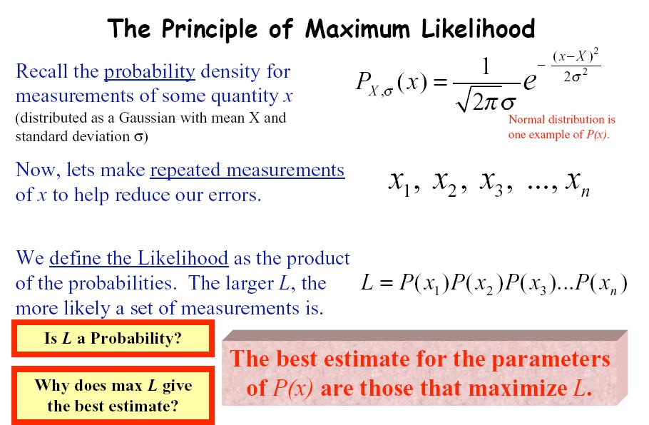
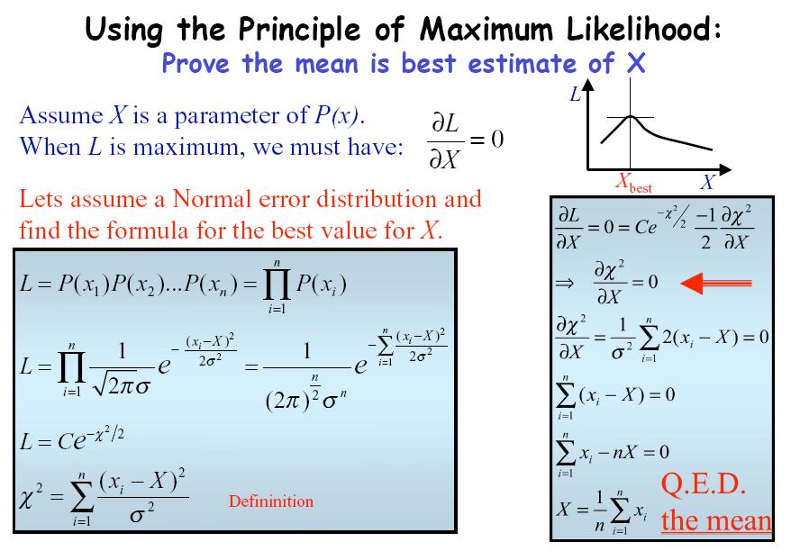
6 Principle of Maximum Likelihood Best estimates of X and s from N measurements (x 1 - x N ) are those for which Prob X,s (x i ) is a maximum
7 Yagil
8 Yagil
9 Yagil
 Yagil")
10 Weighted averages (Chapter 7) Yagil
11 Yagil
12 ± ±
13
14 b) Best estimate is the weighted mean:
15 Y value Linear Relationships: y = A + Bx Data would lie on a straight line, except for errors What is best line through the points? What is uncertainty in constants? How well does the relationship describe the data? Velocity vs. constant acceleration Ohms law Slope = X Value
16 Y value A Rough Cut Best means line close to all points Draw various lines that pass through data points Estimate error in constants from range of values Good fit if points within error bars of line slope = slope = 1.06 slope = X Value
17 Y value More Analytical Best means minimize the square of the deviations between line and points Can use error analysis to find constants, error Slope = 1.01 ± X Value
18 The Details of How to Do This (Chapter 8)
19 Finding the coefficients A and B Want to find A, B that minimize difference between data and line Since line above some data, below other, minimize sum of squares of deviations Find A, B that minimize this sum A B y y i y A Bx y i y y i A Bx i N i1 (y i A Bx i ) 2 deviation of y i y i AN Bx i 0 x iy i A x i B 2 x i 0
20 Finding A and B After minimization, solve equations for A and B Looks nasty, not so bad See Taylor, example 8.1 A B y i AN Bx i 0 x 2 iy i A x i Bx i 0 2 x i y i x i x i y i A B N x y i i x i N x i 2 2 x i y i
21 Uncertainty in Measurements of y Before, measure several times and take standard deviation as error in y Can t now, since y i s are different quantities Instead, find standard deviation of deviations s y s x 1 N 2 1 N N 1 i1 N i1 ( x i x) (y i A Bx i ) 2 2
22 Uncertainty in A and B A, B are calculated from x i, y i Know error in x i, y i ; use error propagation to find error in A, B A distant extrapolation will be subject to large uncertainty s A s y s B s y N N x i 2 2 x i 2 x i
23 Uncertainty in x So far, assumed negligible uncertainty in x If uncertainty in x, not y, just switch them If uncertainty in both, convert error in x to error in y, then add errors actual error in x y Bx s y (equiv) Bs x s y (equiv) equivalent error in y s 2 y Bs x 2
24 Other Functions y Ae Bx Convert to linear Can now use least squares fitting to get ln A and B y Ae Bx ln y ln A Bx
25 Experiment #2 Oscillations and Damping RLC Circuit DC response
26 RLC Circuit Response
27 Graph of RLC Circuit Response
28 Critical Damping Define critical damping time constant No oscillations observed
29 Three Regimes for Damping
30 Lab Objectives 1) Determine w and Q 2) Achieve Critical Damping 3) Determine unknown L
31 Lab 3 Resonance Sinusoidal Response Complete circuit Model circuit
32 Lab 3 Resonance Q w 0 w 2 w 1
33 Uncertainty in Q Q = w 0 /(w 2 - w 1 ) Q = w 0 /(w) where w = w 2 - w 1 eq) = {e(w 0 ) 2 + e(w) 2 } 1/2 e(w 0 ) = d(w 0 )/w 0 e(w) = d(w)/w e(w 2 - w 1 ) = d(w 2 - w 1 )/ w 2 - w 1 d(w 2 - w 1 ) = {d(w 2 ) 2 + d(w 1 ) 2 } 1/2
34 Voltage Response
35 Origin and Voltage Response Derived Equation Origin fit Equation V R I Z R V 0 Z R Z Total R 1 Q 2 V 0 R R w w 0 w 0 w 2 y y = VR x = w A 2 2 x C 1 B C x A = V 0 R R /R B = Q C = w 0
36 Phase Shifts
37 Phase Response
38 Q-Multiplier Maximum voltage across capacitor is Q times driving voltage V 0
39 Outline Lab # 3 1). Preliminary calculations of w 0 and Q 2). Measure w 0 and Q 3). Graph Frequency Response 4). Q dependence on R 5). Q-Multiplier 6). Analysis 7). Conclusions
40 Remember CAPE evaluations Lab Writeup Read next session s lab description, do prelab Homework 5 (Taylor 6.1, 6.4) Read Taylor through chapter 8
Establishing Relationships Linear Least Squares Fitting. Lecture 6 Physics 2CL Summer 2010
 Establishing Relationships Linear Least Squares Fitting Lecture 6 Physics 2CL Summer 2010 Outline Determining the relationship between measured values Physics for experiment # 3 Oscillations & resonance
Normal Distributions Rejection of Data + RLC Circuits. Lecture 4 Physics 2CL Summer 2011
 Normal Distributions Rejection of Data + RLC Circuits Lecture 4 Physics 2CL Summer 2011 Outline Reminder of simple uncertainty propagation formulae Hidden useful formula for estimating uncertainties More
Electricity Designing a Voltmeter c 2 testing Review. Lecture # 7 Physics 2BL Summer 2011
 Electricity Designing a Voltmeter c 2 testing Review Lecture # 7 Physics 2BL Summer 2011 Announcements CAPE evaluations: Important for fine tuning of the course Making changes Giving feedback Name for
Uncertainty, Measurement, and Models. Lecture 2 Physics 2CL Summer Session 2011
 Uncertainty, Measurement, and Models Lecture 2 Physics 2CL Summer Session 2011 Outline What is uncertainty (error) analysis and what can it do for you Issues with measurement and observation What does
MODULE I. Transient Response:
 Transient Response: MODULE I The Transient Response (also known as the Natural Response) is the way the circuit responds to energies stored in storage elements, such as capacitors and inductors. If a capacitor
To find the step response of an RC circuit
 To find the step response of an RC circuit v( t) v( ) [ v( t) v( )] e tt The time constant = RC The final capacitor voltage v() The initial capacitor voltage v(t ) To find the step response of an RL circuit
Gaussians Distributions, Simple Harmonic Motion & Uncertainty Analysis Review. Lecture # 5 Physics 2BL Summer 2015
 Gaussians Distributions, Simple Harmonic Motion & Uncertainty Analysis Review Lecture # 5 Physics 2BL Summer 2015 Outline Significant figures Gaussian distribution and probabilities Experiment 2 review
Practical 1 RC Circuits
 Objectives Practical 1 Circuits 1) Observe and qualitatively describe the charging and discharging (decay) of the voltage on a capacitor. 2) Graphically determine the time constant for the decay, τ =.
Intermediate Lab PHYS 3870
 Intermediate Lab PHYS 3870 Lecture 4 Comparing Data and Models Quantitatively Linear Regression Introduction Section 0 Lecture 1 Slide 1 References: Taylor Ch. 8 and 9 Also refer to Glossary of Important
RC, RL, and LCR Circuits
 RC, RL, and LCR Circuits EK307 Lab Note: This is a two week lab. Most students complete part A in week one and part B in week two. Introduction: Inductors and capacitors are energy storage devices. They
Electromagnetic Oscillations and Alternating Current. 1. Electromagnetic oscillations and LC circuit 2. Alternating Current 3.
 Electromagnetic Oscillations and Alternating Current 1. Electromagnetic oscillations and LC circuit 2. Alternating Current 3. RLC circuit in AC 1 RL and RC circuits RL RC Charging Discharging I = emf R
N H I. 3.2 l When a conducting coil is placed in a magnetic field, the magnetic flux is
 Experiment No : EM 8 Experiment Name: Inductance of a Solenoid Objective: Investigation of the inductance of different solenoids and their dependence on certain parameters of solenoids Theoretical Information
LABORATORY 4 ELECTRIC CIRCUITS I. Objectives
 LABORATORY 4 ELECTRIC CIRCUITS I Objectives to be able to discuss potential difference and current in a circuit in terms of electric field, work per unit charge and motion of charges to understand that
The RLC circuits have a wide range of applications, including oscillators and frequency filters
 9. The RL ircuit The RL circuits have a wide range of applications, including oscillators and frequency filters This chapter considers the responses of RL circuits The result is a second-order differential
Physics 4 Spring 1989 Lab 5 - AC Circuits
 Physics 4 Spring 1989 Lab 5 - AC Circuits Theory Consider the series inductor-resistor-capacitor circuit shown in figure 1. When an alternating voltage is applied to this circuit, the current and voltage
Solution for Fq. A. up B. down C. east D. west E. south
 Solution for Fq A proton traveling due north enters a region that contains both a magnetic field and an electric field. The electric field lines point due west. It is observed that the proton continues
Electric Field and Electric Potential
 1 Electric Field and Electric Potential 2 Prelab Write experiment title, your name and student number at top of the page. Prelab 1: Write the objective of this experiment. Prelab 2: Write the relevant
first name (print) last name (print) brock id (ab17cd) (lab date)
 last name (print) brock id (ab17cd) (lab date)") (ta initials) first name (print) last name (print) brock id (ab17cd) (lab date) Experiment 1 Capacitance In this Experiment you will learn the relationship between the voltage and charge stored on a capacitor;
(ta initials) first name (print) last name (print) brock id (ab17cd) (lab date) Experiment 1 Capacitance In this Experiment you will learn the relationship between the voltage and charge stored on a capacitor;
Introduction to Statistics and Error Analysis II
 Introduction to Statistics and Error Analysis II Physics116C, 4/14/06 D. Pellett References: Data Reduction and Error Analysis for the Physical Sciences by Bevington and Robinson Particle Data Group notes
Physics 240 Fall 2005: Exam #3 Solutions. Please print your name: Please list your discussion section number: Please list your discussion instructor:
 Physics 4 Fall 5: Exam #3 Solutions Please print your name: Please list your discussion section number: Please list your discussion instructor: Form #1 Instructions 1. Fill in your name above. This will
PHYS 241 EXAM #2 November 9, 2006
 1. ( 5 points) A resistance R and a 3.9 H inductance are in series across a 60 Hz AC voltage. The voltage across the resistor is 23 V and the voltage across the inductor is 35 V. Assume that all voltages
Uncertainty, Measurement, and Models Overview Exp #1. Lecture # 2 Physics 2BL Summer Session I 2015
 Uncertainty, Measurement, and Models Overview Exp #1 Lecture # 2 Physics 2BL Summer Session I 2015 Outline What uncertainty (error) analysis can for you Issues with measurement and observation What does
Ch 28-DC Circuits! 1.) EMF & Terminal Voltage! 9.0 V 8.7 V 8.7 V. V =! " Ir. Terminal Open circuit internal! voltage voltage (emf) resistance" 2.
 EMF & Terminal Voltage! 9.0 V 8.7 V 8.7 V. V =! Ir. Terminal Open circuit internal! voltage voltage (emf) resistance 2.") Ch 28-DC Circuits! 1.) EMF & Terminal Voltage! 9.0 V 8.7 V 8.7 V V =! " Ir Terminal Open circuit internal! voltage voltage (emf) resistance" 2.) Resistors in series! One of the bits of nastiness about
Ch 28-DC Circuits! 1.) EMF & Terminal Voltage! 9.0 V 8.7 V 8.7 V V =! " Ir Terminal Open circuit internal! voltage voltage (emf) resistance" 2.) Resistors in series! One of the bits of nastiness about
Switch. R 5 V Capacitor. ower upply. Voltmete. Goals. Introduction
 Switch Lab 6. Circuits ower upply Goals + + R 5 V Capacitor V To appreciate the capacitor as a charge storage device. To measure the voltage across a capacitor as it discharges through a resistor, and
PHYSICS 122 Lab EXPERIMENT NO. 6 AC CIRCUITS
 PHYSICS 122 Lab EXPERIMENT NO. 6 AC CIRCUITS The first purpose of this laboratory is to observe voltages as a function of time in an RC circuit and compare it to its expected time behavior. In the second
Switch. R 5 V Capacitor. ower upply. Voltmete. Goals. Introduction
 Switch Lab 6. Circuits ower upply Goals + + R 5 V Capacitor V To appreciate the capacitor as a charge storage device. To measure the voltage across a capacitor as it discharges through a resistor, and
PHYS 3900 Homework Set #02
 PHYS 3900 Homework Set #02 Part = HWP 2.0, 2.02, 2.03. Due: Mon. Jan. 22, 208, 4:00pm Part 2 = HWP 2.04, 2.05, 2.06. Due: Fri. Jan. 26, 208, 4:00pm All textbook problems assigned, unless otherwise stated,
EE292: Fundamentals of ECE
 EE292: Fundamentals of ECE Fall 2012 TTh 10:00-11:15 SEB 1242 Lecture 14 121011 http://www.ee.unlv.edu/~b1morris/ee292/ 2 Outline Review Steady-State Analysis RC Circuits RL Circuits 3 DC Steady-State
PC1222 Fundamentals of Physics II. Basic Circuits. Data Table 1
 Name: Date: PC1222 Fundamentals of Physics II Basic Circuits 5 Laboratory Worksheet Part A: Ohm s Law and Resistances Resistance Colour Codes 1st 2nd 3rd 4th Resistance R (Ω) Current I (A) Voltage V (V)
Equipotential and Electric Field Mapping
 Experiment 2 Equipotential and Electric Field Mapping 2.1 Objectives 1. Determine the lines of constant electric potential for two simple configurations of oppositely charged conductors. 2. Determine the
Linear and Nonlinear Oscillators (Lecture 2)
") Linear and Nonlinear Oscillators (Lecture 2) January 25, 2016 7/441 Lecture outline A simple model of a linear oscillator lies in the foundation of many physical phenomena in accelerator dynamics. A typical
Linear and Nonlinear Oscillators (Lecture 2) January 25, 2016 7/441 Lecture outline A simple model of a linear oscillator lies in the foundation of many physical phenomena in accelerator dynamics. A typical
Experiment IV. To find the velocity of waves on a string by measuring the wavelength and frequency of standing waves.
 Experiment IV The Vibrating String I. Purpose: To find the velocity of waves on a string by measuring the wavelength and frequency of standing waves. II. References: Serway and Jewett, 6th Ed., Vol., Chap.
The RC Time Constant
 The RC Time Constant Objectives When a direct-current source of emf is suddenly placed in series with a capacitor and a resistor, there is current in the circuit for whatever time it takes to fully charge
Switch. R 5 V Capacitor. ower upply. Voltmete. Goals. Introduction
 Switch Lab 9. Circuits ower upply Goals + + R 5 V Capacitor V To appreciate the capacitor as a charge storage device. To measure the voltage across a capacitor as it discharges through a resistor, and
Modeling. Transition between the TF to SS and SS to TF will also be discussed.
 Modeling This lecture we will consentrate on how to do system modeling based on two commonly used techniques In frequency domain using Transfer Function (TF) representation In time domain via using State
Experiment 2: Projectile Motion
 Experiment 2: Projectile Motion You will verify that a projectile s velocity and acceleration components behave as described in class. A ball bearing rolls off of a ramp, becoming a projectile. It flies
ENGR 2405 Chapter 8. Second Order Circuits
 ENGR 2405 Chapter 8 Second Order Circuits Overview The previous chapter introduced the concept of first order circuits. This chapter will expand on that with second order circuits: those that need a second
Physics 240 Fall 2005: Exam #3. Please print your name: Please list your discussion section number: Please list your discussion instructor:
 Physics 240 Fall 2005: Exam #3 Please print your name: Please list your discussion section number: Please list your discussion instructor: Form #1 Instructions 1. Fill in your name above 2. This will be
Industrial Electricity
 Industrial Electricity PRELAB / LAB 7: Series & Parallel Circuits with Faults Name PRELAB due BEFORE beginning the lab (initials required at the bottom of page 3) PLEASE TAKE THE TIME TO READ THIS PAGE
Linear Systems of ODE: Nullclines, Eigenvector lines and trajectories
 Linear Systems of ODE: Nullclines, Eigenvector lines and trajectories James K. Peterson Department of Biological Sciences and Department of Mathematical Sciences Clemson University October 6, 203 Outline
Experiment 4. RC Circuits. Observe and qualitatively describe the charging and discharging (decay) of the voltage on a capacitor.
 of the voltage on a capacitor.") Experiment 4 RC Circuits 4.1 Objectives Observe and qualitatively describe the charging and discharging (decay) of the voltage on a capacitor. Graphically determine the time constant τ for the decay. 4.2
Experiment 4 RC Circuits 4.1 Objectives Observe and qualitatively describe the charging and discharging (decay) of the voltage on a capacitor. Graphically determine the time constant τ for the decay. 4.2
Measuring the time constant for an RC-Circuit
 Physics 8.02T 1 Fall 2001 Measuring the time constant for an RC-Circuit Introduction: Capacitors Capacitors are circuit elements that store electric charge Q according to Q = CV where V is the voltage
cancel each other out. Thus, we only need to consider magnetic field produced by wire carrying current 2.
 PC1143 2011/2012 Exam Solutions Question 1 a) Assumption: shells are conductors. Notes: the system given is a capacitor. Make use of spherical symmetry. Energy density, =. in this case means electric field
Physics 201. Professor P. Q. Hung. 311B, Physics Building. Physics 201 p. 1/3
 Physics 201 p. 1/3 Physics 201 Professor P. Q. Hung 311B, Physics Building Physics 201 p. 2/3 Summary of last lecture Equipotential surfaces: Surfaces where the potential is the same everywhere, e.g. the
ECE 220 Laboratory 4 Volt Meter, Comparators, and Timer
 ECE 220 Laboratory 4 Volt Meter, Comparators, and Timer Michael W. Marcellin Please follow all rules, procedures and report requirements as described at the beginning of the document entitled ECE 220 Laboratory
Clicker Session Currents, DC Circuits
 Clicker Session Currents, DC Circuits Wires A wire of resistance R is stretched uniformly (keeping its volume constant) until it is twice its original length. What happens to the resistance? 1) it decreases
EXPERIMENT 5A RC Circuits
 EXPERIMENT 5A Circuits Objectives 1) Observe and qualitatively describe the charging and discharging (decay) of the voltage on a capacitor. 2) Graphically determine the time constant for the decay, τ =.
Module 25: Outline Resonance & Resonance Driven & LRC Circuits Circuits 2
 Module 25: Driven RLC Circuits 1 Module 25: Outline Resonance & Driven LRC Circuits 2 Driven Oscillations: Resonance 3 Mass on a Spring: Simple Harmonic Motion A Second Look 4 Mass on a Spring (1) (2)
Ch. 23 Electromagnetic Induction, AC Circuits, And Electrical Technologies
 Ch. 23 Electromagnetic Induction, AC Circuits, And Electrical Technologies Induced emf - Faraday s Experiment When a magnet moves toward a loop of wire, the ammeter shows the presence of a current When
POLYTECHNIC UNIVERSITY Electrical Engineering Department. EE SOPHOMORE LABORATORY Experiment 2 DC circuits and network theorems
 POLYTECHNIC UNIVERSITY Electrical Engineering Department EE SOPHOMORE LABORATORY Experiment 2 DC circuits and network theorems Modified for Physics 18, Brooklyn College I. Overview of Experiment In this
Linear Systems of ODE: Nullclines, Eigenvector lines and trajectories
 Linear Systems of ODE: Nullclines, Eigenvector lines and trajectories James K. Peterson Department of Biological Sciences and Department of Mathematical Sciences Clemson University October 6, 2013 Outline
Physics 115. AC: RL vs RC circuits Phase relationships RLC circuits. General Physics II. Session 33
 Session 33 Physics 115 General Physics II AC: RL vs RC circuits Phase relationships RLC circuits R. J. Wilkes Email: phy115a@u.washington.edu Home page: http://courses.washington.edu/phy115a/ 6/2/14 1
PHYS 1444 Section 004 Lecture #22
 PHYS 1444 Section 004 Lecture #22 Monday, April 23, 2012 Dr. Extension of Ampere s Law Gauss Law of Magnetism Maxwell s Equations Production of Electromagnetic Waves Today s homework is #13, due 10pm,
HOMEWORK 4: MATH 265: SOLUTIONS. y p = cos(ω 0t) 9 ω 2 0
 9 ω 2 0") HOMEWORK 4: MATH 265: SOLUTIONS. Find the solution to the initial value problems y + 9y = cos(ωt) with y(0) = 0, y (0) = 0 (account for all ω > 0). Draw a plot of the solution when ω = and when ω = 3.
HOMEWORK 4: MATH 265: SOLUTIONS. Find the solution to the initial value problems y + 9y = cos(ωt) with y(0) = 0, y (0) = 0 (account for all ω > 0). Draw a plot of the solution when ω = and when ω = 3.
QUESTION BANK SUBJECT: NETWORK ANALYSIS (10ES34)
") QUESTION BANK SUBJECT: NETWORK ANALYSIS (10ES34) NOTE: FOR NUMERICAL PROBLEMS FOR ALL UNITS EXCEPT UNIT 5 REFER THE E-BOOK ENGINEERING CIRCUIT ANALYSIS, 7 th EDITION HAYT AND KIMMERLY. PAGE NUMBERS OF
QUESTION BANK SUBJECT: NETWORK ANALYSIS (10ES34) NOTE: FOR NUMERICAL PROBLEMS FOR ALL UNITS EXCEPT UNIT 5 REFER THE E-BOOK ENGINEERING CIRCUIT ANALYSIS, 7 th EDITION HAYT AND KIMMERLY. PAGE NUMBERS OF
Laboratory 7: Charging and Discharging a Capacitor Prelab
 Phys 132L Fall 2018 Laboratory 7: Charging and Discharging a Capacitor Prelab Consider a capacitor with capacitance C connected in series to a resistor with resistance R as shown in Fig. 1. Theory predicts
Contents. Contents. Contents
 Physics 121 for Majors Class 18 Linear Harmonic Last Class We saw how motion in a circle is mathematically similar to motion in a straight line. We learned that there is a centripetal acceleration (and
Physics 1140 Fall 2013 Introduction to Experimental Physics
 Physics 1140 Fall 2013 Introduction to Experimental Physics Joanna Atkin Lecture 5: Recap of Error Propagation and Gaussian Statistics Graphs and linear fitting Experimental analysis Typically make repeat
Driven Harmonic Oscillator
 Driven Harmonic Oscillator Physics 6B Lab Experiment 1 APPARATUS Computer and interface Mechanical vibrator and spring holder Stands, etc. to hold vibrator Motion sensor C-209 spring Weight holder and
Complete all the identification fields below or 10% of the lab value will be deduced from your final mark for this lab.
 Simple circuits 3 hr Identification page Instructions: Print this page and the following ones before your lab session to prepare your lab report. Staple them together with your graphs at the end. If you
(amperes) = (coulombs) (3.1) (seconds) Time varying current. (volts) =
 = (coulombs) (3.1) (seconds) Time varying current. (volts) =") 3 Electrical Circuits 3. Basic Concepts Electric charge coulomb of negative change contains 624 0 8 electrons. Current ampere is a steady flow of coulomb of change pass a given point in a conductor in
3 Electrical Circuits 3. Basic Concepts Electric charge coulomb of negative change contains 624 0 8 electrons. Current ampere is a steady flow of coulomb of change pass a given point in a conductor in
Physics 218 Lecture 2
 Physics 218 Lecture 2 Dr. David Toback Physics 218, Lecture II 1 In Class Quiz Write down the most important student case study from the Frequently Asked Questions handout Physics 218, Lecture II 2 Announcements:
6.302 Feedback Systems
 MASSACHUSETTS INSTITUTE OF TECHNOLOGY Department of Electrical Engineering and Computer Science 6.302 Feedback Systems Fall Term 2005 Issued : November 18, 2005 Lab 2 Series Compensation in Practice Due
Physics 4. Magnetic Induction. Prepared by Vince Zaccone For Campus Learning Assistance Services at UCSB
 Physics 4 Magnetic Induction Before we can talk about induction we need to understand magnetic flux. You can think of flux as the number of field lines passing through an area. Here is the formula: flux
Fundamentals of DC Testing
 Fundamentals of DC Testing Aether Lee erigy Japan Abstract n the beginning of this lecture, Ohm s la, hich is the most important electric la regarding DC testing, ill be revieed. Then, in the second section,
University of TN Chattanooga Physics 1040L 8/18/2012 PHYSICS 1040L LAB LAB 4: R.C. TIME CONSTANT LAB
 PHYSICS 1040L LAB LAB 4: R.C. TIME CONSTANT LAB OBJECT: To study the discharging of a capacitor and determine the time constant for a simple circuit. APPARATUS: Capacitor (about 24 μf), two resistors (about
ELECTROMAGNETIC OSCILLATIONS AND ALTERNATING CURRENT
 Chapter 31: ELECTROMAGNETIC OSCILLATIONS AND ALTERNATING CURRENT 1 A charged capacitor and an inductor are connected in series At time t = 0 the current is zero, but the capacitor is charged If T is the
Prerequisites: Successful completion of PHYS 2222 General Physics (Calculus) with a grade of C or better.
 with a grade of C or better.") Prepared by: P. Blake Reviewed by: M. Mayfield Date prepared: March 13, 2017 C&GE approved: April 17, 2017 Board approved: May 10, 2017 Semester effective: Spring 2018 Engineering (ENGR) 2000 Circuit Analysis
Prepared by: P. Blake Reviewed by: M. Mayfield Date prepared: March 13, 2017 C&GE approved: April 17, 2017 Board approved: May 10, 2017 Semester effective: Spring 2018 Engineering (ENGR) 2000 Circuit Analysis
Prepare for this experiment!
 Notes on Experiment #8 Theorems of Linear Networks Prepare for this experiment! If you prepare, you can finish in 90 minutes. If you do not prepare, you will not finish even half of this experiment. So,
Designing Information Devices and Systems I Spring 2019 Homework 11
 Last Updated: 2019-04-12 23:38 1 EECS 16A Designing Information Devices and Systems I Spring 2019 Homework 11 This homework is due April 19, 2019, at 23:59. Self-grades are due April 23, 2019, at 23:59.
Basic Electronics. Introductory Lecture Course for. Technology and Instrumentation in Particle Physics Chicago, Illinois June 9-14, 2011
 Basic Electronics Introductory Lecture Course for Technology and Instrumentation in Particle Physics 2011 Chicago, Illinois June 9-14, 2011 Presented By Gary Drake Argonne National Laboratory drake@anl.gov
Review. Spring Semester /21/14. Physics for Scientists & Engineers 2 1
 Review Spring Semester 2014 Physics for Scientists & Engineers 2 1 Notes! Homework set 13 extended to Tuesday, 4/22! Remember to fill out SIRS form: https://sirsonline.msu.edu Physics for Scientists &
Lecture 4: R-L-C Circuits and Resonant Circuits
 Lecture 4: R-L-C Circuits and Resonant Circuits RLC series circuit: What's V R? Simplest way to solve for V is to use voltage divider equation in complex notation: V X L X C V R = in R R + X C + X L L
Poisson distribution and χ 2 (Chap 11-12)
") Poisson distribution and χ 2 (Chap 11-12) Announcements: Last lecture today! Labs will continue. Homework assignment will be posted tomorrow or Thursday (I will send email) and is due Thursday, February
Poisson distribution and χ 2 (Chap 11-12) Announcements: Last lecture today! Labs will continue. Homework assignment will be posted tomorrow or Thursday (I will send email) and is due Thursday, February
Some of the different forms of a signal, obtained by transformations, are shown in the figure. jwt e z. jwt z e
 Transform methods Some of the different forms of a signal, obtained by transformations, are shown in the figure. X(s) X(t) L - L F - F jw s s jw X(jw) X*(t) F - F X*(jw) jwt e z jwt z e X(nT) Z - Z X(z)
Chapter 19 Lecture Notes
 Chapter 19 Lecture Notes Physics 2424 - Strauss Formulas: R S = R 1 + R 2 +... C P = C 1 + C 2 +... 1/R P = 1/R 1 + 1/R 2 +... 1/C S = 1/C 1 + 1/C 2 +... q = q 0 [1-e -t/(rc) ] q = q 0 e -t/(rc τ = RC
Circuits. David J. Starling Penn State Hazleton PHYS 212
 Invention is the most important product of man s creative brain. The ultimate purpose is the complete mastery of mind over the material world, the harnessing of human nature to human needs. - Nikola Tesla
Physics 1140 Experimental Physics 1
 Physics 1140 Experimental Physics 1 Debbie Jin Lecture 1: Introduc>on to Course Measurement Uncertainty Standard Format 1 General Informa>on Lecture instructor: Debbie Jin email: deborah.jin@colorado.edu
Laplace Transform Problems
 AP Calculus BC Name: Laplace Transformation Day 3 2 January 206 Laplace Transform Problems Example problems using the Laplace Transform.. Solve the differential equation y! y = e t, with the initial value
Exam 2 Solutions. Prof. Darin Acosta Prof. Greg Stewart March 27, b 5Ω ->i 1 <- i 2 5Ω. 3V 10Ω 6 V - - i 3 d c 10Ω
 PHY49 Spring 6 Exam Solutions Prof. Darin Acosta Prof. Greg Stewart March 7, 6 Exam Solutions a b 5Ω ->i 1
Experiment 3: Resonance in LRC Circuits Driven by Alternating Current
 Experiment 3: Resonance in LRC Circuits Driven by Alternating Current Introduction In last week s laboratory you examined the LRC circuit when constant voltage was applied to it. During this laboratory
Meeting of Modern Science and School Physics: College for School Teachers of Physics in ICTP. 27 April - 3 May, 2011
 2234-13 Meeting of Modern Science and School Physics: College for School Teachers of Physics in ICTP 27 April - 3 May, 2011 Computer based tools for active learning in the introductory physics course David
Physics 1050 Experiment 3. Force and Acceleration
 Force and Acceleration Prelab uestions! These questions need to be completed before entering the lab. Please show all workings. Prelab 1: Draw the free body diagram for the cart on an inclined plane. Break
Chapter 6 DIRECT CURRENT CIRCUITS. Recommended Problems: 6,9,11,13,14,15,16,19,20,21,24,25,26,28,29,30,31,33,37,68,71.
 Chapter 6 DRECT CURRENT CRCUTS Recommended Problems: 6,9,,3,4,5,6,9,0,,4,5,6,8,9,30,3,33,37,68,7. RESSTORS N SERES AND N PARALLEL - N SERES When two resistors are connected together as shown we said that
= e = e 3 = = 4.98%
 PHYS 212 Exam 2 - Practice Test - Solutions 1E In order to use the equation for discharging, we should consider the amount of charge remaining after three time constants, which would have to be q(t)/q0.
EXPERIMENT 07 TO STUDY DC RC CIRCUIT AND TRANSIENT PHENOMENA
 EXPERIMENT 07 TO STUDY DC RC CIRCUIT AND TRANSIENT PHENOMENA DISCUSSION The capacitor is a element which stores electric energy by charging the charge on it. Bear in mind that the charge on a capacitor
MASSACHUSETTS INSTITUTE OF TECHNOLOGY Department of Physics 8.02 Spring 2003 Experiment 17: RLC Circuit (modified 4/15/2003) OBJECTIVES
 OBJECTIVES") MASSACHUSETTS INSTITUTE OF TECHNOLOGY Department of Physics 8. Spring 3 Experiment 7: R Circuit (modified 4/5/3) OBJECTIVES. To observe electrical oscillations, measure their frequencies, and verify energy
MASSACHUSETTS INSTITUTE OF TECHNOLOGY Department of Physics 8. Spring 3 Experiment 7: R Circuit (modified 4/5/3) OBJECTIVES. To observe electrical oscillations, measure their frequencies, and verify energy
8 sin 3 V. For the circuit given, determine the voltage v for all time t. Assume that no energy is stored in the circuit before t = 0.
 For the circuit given, determine the voltage v for all time t. Assume that no energy is stored in the circuit before t = 0. Spring 2015, Exam #5, Problem #1 4t Answer: e tut 8 sin 3 V 1 For the circuit
Exam 2, Phy 2049, Spring Solutions:
 Exam 2, Phy 2049, Spring 2017. Solutions: 1. A battery, which has an emf of EMF = 10V and an internal resistance of R 0 = 50Ω, is connected to three resistors, as shown in the figure. The resistors have
Written homework due on Monday at the start of class Online homework due on Tuesday by 8 am
 Homework #12 Written homework due on Monday at the start of class Online homework due on Tuesday by 8 am Exam 3 Wednesday May 6 from 7 to 9 pm Make-up exams need to be scheduled no later than Friday this
Equipotential and Electric Field Mapping
 Experiment 1 Equipotential and Electric Field Mapping 1.1 Objectives 1. Determine the lines of constant electric potential for two simple configurations of oppositely charged conductors. 2. Determine the
Electromagnetism lab project
 Electromagnetism lab project Contents 1. Overview of the course 2. How to analyse errors in measurements 3. How to make graphical representations (plots) Overview Four lab experiments Biot Savart s law
Dynamic circuits: Frequency domain analysis
 Electronic Circuits 1 Dynamic circuits: Contents Free oscillation and natural frequency Transfer functions Frequency response Bode plots 1 System behaviour: overview 2 System behaviour : review solution
Marwadi University Draft Syllabus for Bachelor of Technology Electronics and Communication. Subject Code: 03EC0302
 Subject Code: 03EC0302 Subject Name: Circuits and Networks B. Tech. Year II (Semester III) Objective: After completion of this course, student will be able to: 1. To introduce electric circuits and its
10/11/2018 1:48 PM Approved (Changed Course) PHYS 42 Course Outline as of Fall 2017
 PHYS 42 Course Outline as of Fall 2017") 10/11/2018 1:48 PM Approved (Changed Course) PHYS 42 Course Outline as of Fall 2017 CATALOG INFORMATION Dept and Nbr: PHYS 42 Title: ELECTRICITY & MAGNETISM Full Title: Electricity and Magnetism for Scientists
10/11/2018 1:48 PM Approved (Changed Course) PHYS 42 Course Outline as of Fall 2017 CATALOG INFORMATION Dept and Nbr: PHYS 42 Title: ELECTRICITY & MAGNETISM Full Title: Electricity and Magnetism for Scientists
EE292: Fundamentals of ECE
 EE292: Fundamentals of ECE Fall 2012 TTh 10:00-11:15 SEB 1242 Lecture 20 121101 http://www.ee.unlv.edu/~b1morris/ee292/ 2 Outline Chapters 1-3 Circuit Analysis Techniques Chapter 10 Diodes Ideal Model
Physics 1308 Exam 2 Summer 2015
 Physics 1308 Exam 2 Summer 2015 E2-01 2. The direction of the magnetic field in a certain region of space is determined by firing a test charge into the region with its velocity in various directions in
Physics for Scientists & Engineers 2
 Electromagnetic Oscillations Physics for Scientists & Engineers Spring Semester 005 Lecture 8! We have been working with circuits that have a constant current a current that increases to a constant current
Physics 191 Free Fall
 Physics 191 Free Fall 2016-09-21 1 Introduction 2 2 Experimental Procedure 2 3 Homework Questions - Hand in before class! 3 4 Data Analysis 3 4.1 Prepare the data in Excel..................................
Designing Information Devices and Systems I Fall 2018 Lecture Notes Note Introduction to Capacitive Touchscreen
 EES 16A Designing Information Devices and Systems I Fall 2018 Lecture Notes Note 16 16.1 Introduction to apacitive Touchscreen We ve seen how a resistive touchscreen works by using the concept of voltage