Viscous Fluid Structure Interaction Response of Composite Hydrofoils
|
|
|
- Benjamin Mills
- 5 years ago
- Views:
Transcription
1 This is a preprint of the following article, which is available from Yingqian Liao, Nitin Garg, Joaquim R. R. A. Martins, and Yin Lu Young. Viscous Fluid Structure Interaction Response of Composite Hydrofoils. Composite Structures, 212 (219) The published article may differ from this preprint, and is available by following the DOI: https: //doi.org/1.116/j.compstruct Viscous Fluid Structure Interaction Response of Composite Hydrofoils Yingqian Liao 1, Nitin Garg 1, Joaquim R. R. A. Martins 2, Yin Lu Young 1 1 Department of Naval Architecture and Marine Engineering, University of Michigan, Ann Arbor, MI, sdepartment of Aerospace Engineering, University of Michigan, Ann Arbor, MI, 4819 Abstract Composite materials are increasingly used in hydrodynamic lifting surfaces due to their higher specific strength and favorable fatigue properties. A set of parametric studies are performed to investigate the influence of fiber orientation on the vibration characteristics and load-dependent bend-twist coupled behavior of composite hydrofoils in viscous flow. A 3-D Reynolds-averaged Navier Stokes (RANS) solver is coupled with a 3-D finite-element method (FEM) to predict the fluid-structure response of cantilevered composite hydrofoils made of unidirectional carbon fiber reinforced polymer (CFRP). Fiber orientation changes the modal characteristics of composite hydrofoils, as well as the hydroelastic response. The bending-up and nose-down material bend-twist coupling leads to lower hydrodynamic load coefficients with increasing flow speed, as well as delayed separation, stall, and static divergence. The opposite trend is observed when the fiber orientation results in a bending-up and nose-up material bend-twist coupling. Material failure index contours show that the fiber orientation affects the location of failure. These parametric studies provide guidance for future design and optimization of composite hydrodynamic lifting surfaces. 1 Introduction According to the Review of Maritime Transport of United Nations Conference on Trade and Development [1], maritime transport still contributes to more than 8% of the total world trade. Thus, improving the marine transport efficiency is critical for global sustainability, as well as for economic worldwide growth. Additionally, increasingly stringent energy efficiency requirements for ships [2] encourages researchers and 1
2 ship builders to look for ways to increase the efficiency of maritime transport. Two promising ways to address this are to use new materials for the hull and propulsor, and to use more sophisticated design methodologies, such as multidisciplinary design optimization [3 13]. Traditionally, marine propellers are made of metallic alloys such as nickel aluminum bronze (NAB) [9, 14, 15]. NAB has the advantages of high-stiffness, anti-biofouling, good corrosion resistance in salt water, and high resistance to cavitation erosion. Another reason to use NAB is that a great deal of experience and data have been accumulated on its use and properties. However, the performance of metallic structures is now reaching its limits. Even a well-designed metallic propeller undergoes a noteworthy efficiency loss when operating at off-design conditions [9]. Thanks to recent advances in fiber-reinforced materials, as well as the development of reliable high-quality manufacturing processes, we can now take advantage of new composite materials to improve the efficiency and reliability of marine lifting surfaces. Composite materials have already been widely used in aerospace and wind energy applications. Carbon fiber reinforced polymers (CFRPs) have become one of the main materials in aircraft since their introduction in 197s [16, 17]. Aeroelastic tailoring via composite material layup has shown to be capable of increasing the critical divergence and flutter speed [18]. A more recent work by Brooks et al. [19] showed a reduction in fuel burn and wing weight when using numerical optimization to design high-aspect ratio wings with composites. Hayat and Ha [2] showed that adding ply-thickness unbalance to ply-angle and ply-material unbalances in wind turbine design reduced the fatigue load and reduced the pitch-actuator duty. Compared to aerospace designs, the use of composites in marine applications is more challenging due to the much higher fluid density of water, and the harsher marine environment. Many composite marine hydrodynamic lifting bodies are based on cantilevered structures, including propellers, turbine blades, hydrofoils, keels, rudders, and different control surfaces [9, 21]. Composite materials are preferred because of their higher strength-to-weight ratio, which allows for weight reduction while satisfying the strength requirements, higher damping for reducing vibration and mitigating noise [22, 23], and self-adaptability through strategic tailoring of material bend-twist coupling behavior. Isotropic cantilevered structures experience flow-induced bend-twist coupling when the center of lift does not coincide with the elastic axis location. In addition to flow-induced bend-twist coupling, material anisotropy can introduce additional bend-twist coupling that can be used to passively tailor the hydroelastic response of the composite structures to improve performance [9 11]. Composite materials also have disadvantages, such as complex failure mechanisms, requirements of advanced manufacturing techniques, and impact damage followed by water absorption, but we can avoid the relevant negative consequences by enforcing the appropriate constraints in multidisciplinary design optimization. Various numerical works have been conducted to investigate the hydroelastic behaviors of marine lifting surfaces and optimize the designs. Lin [24] first conducted a finite-element analysis on a composite propeller blade to estimate its performance. Recently, a 3-D boundary element method (BEM) has been coupled with a 3-D finite element method (FEM) for the fluid-structure interaction analysis of adaptive composite marine propellers [1, 11, 25 27]. The 3-D BEM-FEM coupled model is able 2
3 to predict the hydroelastic performance, cavitation or ventilation patterns, stresses, deformations, vibration characteristics, and potential material failure mechanisms of composite marine propellers in spatially varying flow. These numerical works showed that tailoring of anisotropic properties of composites can increase the overall efficiency and delay cavitation inception of marine propellers compared to metallic counterparts when operating in a spatially varying wake [1, 11, 25 28]. Plucinski et al. [28] used the same coupled 3-D BEM-FEM method with genetic algorithms to optimize a multilayered composite propeller by minimizing the gap between the optimal operating angles and the deformed pitched angles over several flow conditions. To find an optimal fiber orientation for reducing the total fuel consumption, Blasques et al. [8] used a gradient-free optimization algorithm on a BEM-FEM coupled model. They found that the curved fiber path was more efficient than the straight path. Similarly, experimental work showed that passive de-pitching action induced by material bend-twist coupling reduced the tip loading and therefore delayed the cavitation inception [9, 29]. Young et al. [15] provided experimental measurement and numerical analysis of the performance of three composite hydrofoils with different orientation for the structural CFRP layers, and compared their performance to a rigid stainless steel hydrofoil. They concluded that the material bend-twist coupling had a significant effect on the mode shapes and modal frequencies, and modified the hydrodynamic forces, the stall boundary, and the static divergence speed. Most of the previous work on composite hydrodynamic lifting surfaces used lowfidelity tools, such as the BEM method, which assumes inviscid and irrotational flow. Low-fidelity tools are favored due to their low computational cost, but they cannot capture viscous effects such as separation and stall. Considering viscous effects is critical to yield a reliable estimation of flow separation and resultant change in pressure distribution, lift, drag, moment, cavitation inception speed, bend-twist deformations, vibrations, noise, and material failure. Hence, high-fidelity simulations are required to capture viscous fluid-structure interaction effects and accurately predict the performance of composite marine structures. Garg et al. [3] developed a framework for high-fidelity design optimization of hydrofoils that couples a Reynolds-averaged Navier Stokes (RANS) solver to a structural finite element method (FEM) solver. This framework was originally developed for the design of aircraft wings by Kenway at al. [31, 32] and is called MACH (multidisciplinary design optimization of aircraft configurations with high-fidelity). It uses a gradientbased approach with an efficient gradient computation that enables optimization with respect to large numbers of shape and structural sizing variables. Garg et al. [3] performed the shape optimization of metal hydrofoils considering cavitation and strength constraints and the optimized design was validated by experiments [33]. The eventual goal of our work is to design adaptive marine lifting surfaces that take advantage of the tailoring of anisotropic composites using MACH. However, prior to design, it is crucial that we understand the basic physics that govern the response of composite hydrodynamic lifting bodies, including its steady-state hydroelastic response and vibration characteristics. In addition, although MACH has already been used to perform the design optimization of composite aircraft wings [19, 34], the wing structures were modeled with shell finite elements, while we require solid composite finite elements 3
4 for modeling hydrofoils because of the thicker sections required to withstand the higher loads caused by the higher fluid density. To address the needs and motivation stated above, the objectives of this work are to (1) develop and verify a high-fidelity hydrostructural solver for the analysis of the hydroelastic performance and the susceptibility to material failure of composite hydrofoils in viscous flow, and to predict the relevant free vibration characteristics, and (2) improve the understanding of load-dependent bend-twist coupling effects on the hydroelastic performance of composite hydrofoils in viscous flow through numerical simulations. 2 Methodology In this work, we implemented an approach to model composite structures with orthotropic materials using solid elements in MACH. We then used the MACH framework to simulate the hydroelastic response of composite hydrofoils with different unidirectional CFRP orientations and to analyze the influence of the fiber orientation on the response. The geometry of the hydrofoil is generated by pygeo, which is a CAD-free python module tool using free-form deformation volume approach [35]. We import the geometry into ICEM-CFD to generate surface mesh, and use pyhyp to extrude the surface mesh into a hyperbolic volume mesh. The computational fluid dynamics solver in MACH is ADflow, a second order finitevolume solver. ADflow solves the Euler, laminar Navier Stokes, and RANS equations on multiblock or overset meshes. Mader et al. [36] and Lyu et al. [37] have enabled ADflow to compute sensitivities with respect to a large number of variables by implementing an adjoint method, which is critical for gradient-based optimization. In the current work, the Spalart Allmaras (SA) [38] turbulence model is used in the RANS equations. For computational efficiency, we start solving the equations by diagonalized alternating direction implicit and approximate Newton Krylov algorithms, and then switch to Newton Krylov solver after the residual has reduced below a given tolerance. The structural solver used in the MACH framework is the Toolkit for the Analysis of Composite Structures (TACS) [39]. TACS is a parallel, general 3-D FEM solver for structural analysis that can also compute gradients using an adjoint method. TACS specializes in solving ill-conditioned thin-shell structures problems, which are common in aircraft design. However, a solid interior structure is required for hydrodynamic lifting bodies due to the higher fluid loading. Therefore, we implemented solid orthotropic elements in TACS, more specifically, an 8-node brick element (CHEXA8) to simulate the response of composite structures using the solid element [4]. We model the composite hydrofoils using the orthotropic material properties, which require nine independent constants for their stress-strain relationship. When the fibers are not aligned with global coordinates (Figure 1), a transformation of stress and strain is required. The final constitutive equations for orthotropic elements in global coordinates can be found in Appendix A. The CFD and the structural solvers described above are coupled to predict the hydrodynamic loads, solid stresses, and deformations for given flow conditions. The 4
5 hydrodynamic loads (pressure and shear stress distributions) computed by ADflow are transferred to the structural solver using the method of virtual work [32, 41]. The displacements from the structural solution are extrapolated to the CFD surface mesh through rigid links [32, 41], and are propagated to the volume mesh using a mesh deformation algorithm [42]. 3 Verification The CFD solver has already been validated in the work of Garg et al. [3, 43]. Hence, the objective of this section is to verify TACS for composite structures. We verify the new solid orthotropic elements in TACS by comparing the predicted modal analysis results and static pressure deformation results with those obtained using the commercial solver ABAQUS with 8-noded brick element (C3D8). In the second part, we perform FEM mesh and CFD mesh convergence studies to determine the appropriate mesh size to be used. 3.1 Free vibration response and static deformation comparison To verify the TACS computations, we use the plate model made of unidirectional CFRP, as shown in Figure 1, where the plate is cantilevered at the left side is fixed. The material properties for the composite plate are listed in Table 1, which are the same as the values used in the study by Kramer et al. [21]. The fiber orientation angle θ f is defined relative to the spanwise axis and is positive towards the plate leading edge, as shown in Figure 1 by the axis labeled 2. Positive values of θ f indicate fibers that are rotated forward relative to the spanwise axis, while negative values indicate fibers are rotated backward. Table 1: Composite plate material properties and water properties used to predict the in-air and in-water natural frequencies shown in Figure 2. Symbol Description Value Units ρ s Solid density 15 Kg/m 3 E 2 Young s modulus GPa E 1, E 3 Young s modulus 9.8 GPa G 12, G 23 Shear modulus 5.29 GPa G 13 Shear modulus.28 GPa ν 12, ν 23 Poisson s ratio.32 ν 13 Poisson s ratio.29 ρ f Fluid density 998 Kg/m 3 K f Fluid bulk modulus 2.2 GPa In Table 2, we see that the first two in-air natural frequencies of the composite plate with θ f = 3 using four different meshes show good agreement between the two FEM solvers. The fine mesh listed in Table 2 is used for modal analysis for various θ f in 5
6 Figure 1: Cantilevered plate (with the fine mesh and dimensions) used for the verification study. The fixed edge is on the left. Red axes represent global coordinates, while dark blue axes represent the local coordinate with the fibers aligned along the 2-direction, which is at a positive θ f relative to the spanwise axis. Figure 2. The results shown on the left side of Figure 2 demonstrate good agreement between TACS and ABAQUS for the first four predicted in-air natural frequencies. The maximum discrepancy in frequencies for the first in-air mode is.9% for θ f = 9 (i.e, fibers aligned with the streamwise direction), while the maximum discrepancy is.8% for the fourth in-air mode. Table 2: Verification of the in-air natural frequencies for various structural mesh resolutions for a cantilevered plate with θ f = 3. Mesh n x n y n z Mode 1 [Hz] Mode 2 [Hz] ABAQUS TACS ABAQUS TACS Coarse Medium Fine Finest Due to the added mass effect in water, the vibration characteristics can change substantially. The right side of Figure 2 shows the first four predicted in-water natural frequencies obtained using ABAQUS. Acoustic elements are used to simulate the water, and non-reflecting boundary conditions are applied at the edges of the acoustic fluid domain. The assumed properties for water are listed in Table 1. As shown in Figure 2, the in-water frequencies of the plate are much lower than the corresponding in-air frequencies. This is consistent with findings from previous numerical and experimental 6
7 Modal frequency [Hz] In-air Mode 4 In-air from TACS In-air from ABAQUS In-water from ABAQUS 5 4 In-water 3 2 Mode 3 Mode 2 1 Mode f [ / ] Figure 2: Comparison of the first four predicted in-air natural frequencies (left half plane) from ABAQUS (open symbols) and TACS (star symbols), and comparison of the first four in-water natural frequencies (right half plane, calculated from ABAQUS) for the plate of Figure 1 with varying fiber orientation angle θ f. Note that the natural frequencies are much lower in water due to added mass effects. 7
8 work [9, 15, 21, 44, 45]. The predicted in-air and in-water mode shapes are shown in Figure 3. The contours represent the scaled displacement amplitude, which is the magnitude of the scaled displacement vector. Since the displacement amplitude of the modal analysis results is not physical, the contour scales are for visualization of the mode shape only. As shown in Figure 3, the first mode is primarily bending, while the second mode can be bending or twisting, depending on the fiber orientation. Bending motion is accompanied by a large volume of displaced water, which leads to higher fluid inertial resistance, causing a greater reduction in natural frequencies when operating in water. Since the effect of the surrounding fluid is different for bending-dominated versus twisting-dominated modes, the order of the modes can switch with fiber orientation, and can be different than that in air. Nevertheless, for the plate shown in Figure 1, the in-air and in-water mode shapes are similar, and no mode switching is observed. To further verify TACs, comparisons of the predicted tip bending δ tip and tip twist θ tip deformations obtained using TACS and ABAQUS for the plate are shown in Figure 4. The results correspond to the plate subject to a uniform pressure of Pa. Good agreement is observed between these two FEM solvers. The maximum discrepancy of δ tip is 1.87% for θ f = 9. The maximum difference of θ tip is less than.3 for θ f = Mesh convergence study for a composite hydrofoil The previous section verified the new solid composite element formulation in TACS. The objective of this section is to perform a convergence study to determine the optimal mesh for the composite hydrofoil to be used to produce our results. We first present the geometry and material properties of the hydrofoil, followed by FEM and CFD mesh convergence studies Hydrofoil model For a geometry that is more realistic than a simple cantilevered plate, we use a canonical linearly tapered hydrofoil composed of unidirectional CFRP with no built-in twist to study the hydroelastic response. The cross section is a modified NACA 9 with a thicker trailing edge than the original section [46]. The hydrofoil has a span of 2b =.6 m, a mean chord of c =.9 m, and a taper ratio of.5, as shown in Figure 5. The resulting aspect ratio of the hydrofoil is The bottom plot in Figure 5 shows the structural mesh, which has 121,8 elements. Fixed boundary conditions are enforced at the root. The angle θ f is defined relative to the spanwise axis and is positive towards the foil leading edge. Unidirectional CFRP is used throughout in these studies; its material properties are listed in Table 3. All computations in the mesh convergence study are performed with θ f = 3 unless otherwise stated. All hydrostructural computations are performed at a Reynolds number of 1 6 unless otherwise stated FEM mesh convergence study The convergence study results for the predicted in-air natural frequencies are shown in Table 4. The difference in the third mode frequency between TACS and ABAQUS 8
![θf [ ] Mode 1](/docs-images/95/122856789/images/9-0.jpg "Mode 2 Mode 3")


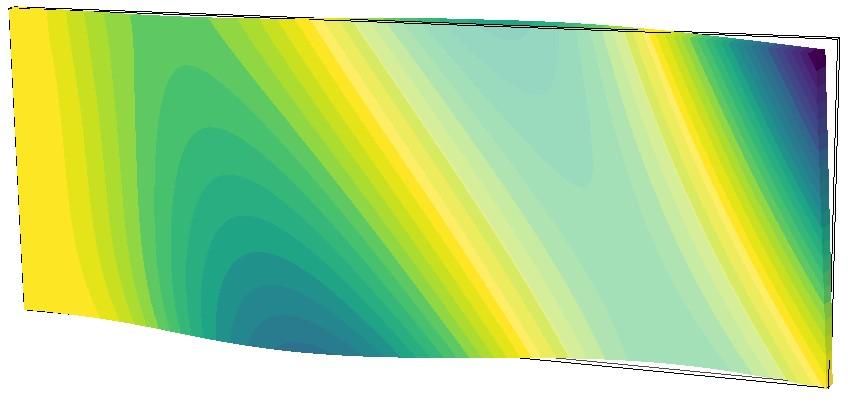


9 θf [ ] Mode 1 Mode 2 Mode 3 Mode 4 Wet Dry Wet 45 Dry Wet 75 Dry Figure 3: Comparison of the first four predicted in-air mode shapes and first four predicted in-water mode shapes of a cantilevered foil for unidirectional fiber orientations θf =, 45, 75 obtained using ABAQUS. The contours represent the scaled displacement amplitude. Note that the contour legend only shows a normalized range and does not imply the actual displacement magnitude. 9
10 2/tip=c [-] tip[ / ] ABAQUS TACS f [ / ] Figure 4: Comparison of the predicted tip bending and tip twist deformations from ABAQUS and TACS for the composite plate. The deflections are measured at the mid-chord at the tip. Table 3: CFRP material properties. Symbol Description Value Units ρ s Solid density 154 Kg/m 3 E 1 Young s modulus 13.4 GPa E 2 Young s modulus GPa E 3 Young s modulus 9.4 GPa G 12, G 23 Shear modulus 3.9 GPa G 13 Shear modulus 3.3 GPa ν 12, ν 23 Poisson s ratio.25 ν 13 Poisson s ratio.45 X T, Z T / X C, Z C Transverse tensile/compressive strength 5/25 MPa S 12, S 23 Shear strength 7 MPa S 13 Shear strength 26 MPa 1

11 Figure 5: Hydrostructural analysis of the CFRP hydrofoil with θ f = 3 at Re = 1 6 and α = 6. Top: CFD mesh for the cantilevered NACA 9 hydrofoil with 1,73,52 cells. Bottom: Structural mesh and displacement magnitude contours on the deformed geometry using with 121,8 8-node linear brick elements. 11
12 is only.99%. Increasing the mesh resolution from medium to fine only changes the third in-air natural frequency by.8% in the TACS analysis. In addition to the in-air natural frequencies predicted using TACS, we present the structural mesh convergence study by the hydrostructural analysis of the composite hydrofoil with θ f = 3 and angle of attack of 2. The angle of attack (α) is defined as the angle between the chord line at the root of the hydrofoil and the free stream, and is positive when the leading edge is up. A CFD mesh with 4,924,8 cells (y + max = 7.5) is used in ADflow for all cases. The resultant lift coefficient C L, drag coefficient C D, pitch moment coefficient C M, non-dimensionalized tip bending deformation 2δ tip /c, and tip twisting θ tip are summarized in Table 5. C M is defined about mid chord at the root and positive nose up. Table 5 shows that the 121,8 element mesh yields a good balance between computational efficiency and the accurate hydrostructural response prediction. Table 4: FEM mesh convergence study for the in-air natural frequencies computed using 8-node linear brick elements: C3D8 in ABAQUS and CHEXA8 in TACS. Mesh Elements n y n x n z Mode 1 [Hz] Mode 2 [Hz] Mode 3 [Hz] ABAQUS TACS ABAQUS TACS ABAQUS TACS Coarse 73, Medium 121, Fine 187, Finest 271, Table 5: FEM mesh convergence study for the hydrodynamic coefficients, tip bending, and tip twist obtained using TACS coupled with ADflow, for which a mesh of 4,924,8 cells is used. Mesh Elements C L C D C M 2δ tip /c θ tip [ ] Coarse 73, Medium 121, Fine 187, Finest 271, CFD mesh convergence study The CFD convergence study is completed with five different mesh sizes, as listed in Table 6. All these results correspond to the same hydrofoil as above, at the same flow condition (Re = 1 6 and α = 2 ). The same structural mesh with 187,1 elements is used in TACS for this study. The results are summarized in Table 6. The difference between experimental values marked in Figure 6 and the Richardson extrapolation of the numerical results is partly due to the difference in actual material used in the experiment versus the material assumed in this study. Since our goal is to demonstrate the capability of the MACH framework to perform coupled hydrostructural analysis with 12
13 composite solid elements, we select the L3 CFD mesh shown in Table 6 to generate the subsequent results for a good balance between accuracy and computational efficiency. This mesh has y + max = 1, which is small enough such that no wall function is needed. Table 6: CFD mesh convergence study of the hydrodynamic coefficients with a constant FEM mesh of 187,1 elements. The L3 mesh is selected for subsequent analysis considering the balance between accuracy and computational cost. Mesh Cells C L C D L1 8,588, L2 4,924, L3 1,73, L4 615, L5 76, CD # L L1 L2 12 RE 5 1 #1-5 L5 2 1 RE L1 L2 L3 L RE L1 L2 L3 L4 CL Numerical (CFRP) Experiment (CFRP-GFRP Young et al. 218) L !2=3 #1-4 N Figure 6: CFD mesh convergence study for hydrostructural analysis using same FEM mesh with 187,1 elements and CFD meshes listed in Table 6. Results computed with Richardson extrapolation (RE) are shown as red filled symbols. 13
14 Modal frequency [Hz] 4 Results In the previous section, we verified the convergence characteristics of the FEM and CFD solvers. We now turn to our main goal, which is to investigate the influence of fiber orientation on the hydroelastic response of the composite hydrofoils. We first show results for modal and hydrostructural analyses, and then discuss the influence of the fiber orientation on the hydroelastic performance. Finally, we discuss the influence of fiber orientation on the susceptibility to static divergence and to material matrix/compressive cracking and delamination in tension/compression failures. 4.1 Free vibration response Understanding how the free vibration response varies with fiber orientation is important because it sheds light on the stiffness and the material bend-twist coupling behavior, which in turn affects the hydroelastic performance. In addition, it is important to understand how the natural frequencies change with fiber orientation to avoid resonance and other hydroelastic instability issues. Based on the FEM mesh convergence study of Section 3.2.2, we selected the 121,8 element mesh for all the TACS computations. The predicted in-air natural frequencies for θ f ranging from 9 to 9 are plotted in Figure 7 for both TACS and ABAQUS computations. The results from the two solvers show excellent agreement for all investigated θ f TACS ABAQUS Mode 3 Mode 4 4 Mode 2 2 Mode f [ / ] Figure 7: First four in-air natural frequencies computed with ABAQUS and TACS for the cantilevered CFRP hydrofoil (shown in Figure 5) for a range of θ f. The predicted mode shapes from TACS are shown in Figure 8, where the contours represent the scaled displacement amplitude, and a similar plot for ABAQUS computations is included in Appendix B. The mode shapes from TACS and ABAQUS are almost identical. The mode shapes are important because the displacements govern the 14
15 fluid added mass, which has a significant impact on the in-water natural frequencies, as illustrated earlier in Figure 2. In Figure 8 we can see that the first modes for all θ f are bending-dominated because of the high aspect ratio of the hydrofoil. When the fibers are oriented away from the spanwise axis (either forward or backward), the bending rigidity is decreased, which is evident through the decrease of the first mode frequency with increasing θ f in Figure 7. Similarly, while the second mode for θ f = is primarily twisting, a combination of bending and twisting can be observed from the mode shapes for θ f. As θ f increases, the bending rigidity weakens to an extent where the second mode becomes the second bending mode and the third mode becomes the first twisting mode. In addition, the twist direction is opposite for θ f > and θ f <, which has direct implications on the hydroelastic response, as we will see later. For the fourth mode, when θ f > 3, an in-plane (or lead-lag) mode develops, while second order coupled bending and twisting is observed for θ f < 3. Overall, the results in Figures 7 and 8 demonstrate that the natural frequencies and mode shapes vary significantly with the fiber orientation, suggesting the possibility of tailoring the fiber orientation to avoid resonant vibrations and tailoring the bend-twist coupling response to improve the hydroelastic performance. 4.2 Hydrostructural response As suggested earlier, tailoring the material bend-twist coupling by varying the fiber orientation has a direct impact on the hydroelastic displacement of composite hydrofoils. This in turn impacts hydrodynamic loads, drag, lift, flow separation and stall boundaries, critical static divergence speed, and material failure location. We compare the results for three different hydrofoils, each analyzed for two different cases in Figure 9. The three hydrofoils have an identical unloaded geometry and consist of two CFRP hydrofoils with fibers swept backward (θ f = 3 ) and fibers swept forward (θ f = +3 ), and a solid stainless steel hydrofoil. The two conditions are a fixed angle of attack (α = 1 ), shown on the left of half of Figure 9, and a fixed lift coefficient (C L =.75), shown on the right. For each of these cases, Figure 9 shows the initial and deformed geometries, streamlines, pressure coefficient contours on the foil suction side, as well as tip vortex streamlines and spanwise lift distributions for two flow conditions. The elliptical lift distributions are shown as a reference, since they represent the theoretical ideal distribution with minimum induced drag. From Figure 9, we can see that while the stainless hydrofoil exhibits negligible deformation, the CFRP hydrofoils are much more flexible. Changing the fiber orientation effectively moves the elastic axis of hydrofoil, inducing bend-twist coupling. The CFRP hydrofoil with θ f = 3 yields bending-up and nose-up bend-twist coupling, while the one with θ f = +3 yields bending-up and nose-down bend-twist coupling. Hence, at α = 1, the hydrofoil with θ f = 3 has a higher lift coefficient than the stainless steel and θ f = +3 hydrofoils, because of the higher overall effective angle of attack caused by the nose-up twist. Excessive effective angle of attack leads to flow separation and reduction in lift when stall develops. As shown on the left plots in Figure 9, when α = 1 for the for θ f = 3 hydrofoil, the effective angle of attack is so large that 15
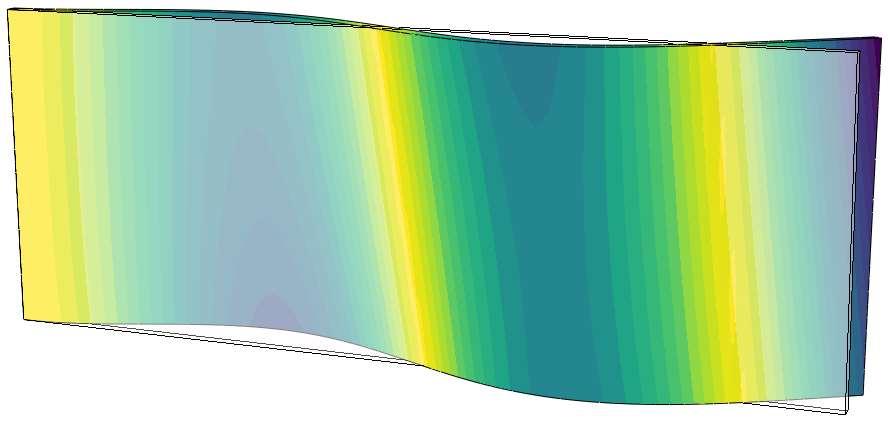
![θf [ ] Mode 1 Mode 2 Mode 3 Mode 4-45 -3-15 15 3 45](/docs-images/95/122856789/images/16-0.jpg "Figure 8: First four predicted in-air mode shapes")


16 θf [ ] Mode 1 Mode 2 Mode 3 Mode Figure 8: First four predicted in-air mode shapes for a range of θf obtained using TACS. The color map represent the scaled displacement amplitude. Note that the contour legend only shows a normalized range and does not imply the actual displacement magnitude. The predicted mode shapes using TACS agree well with those obtained using ABAQUS (shown in Appendix B). 16
 and θ f = 3 (middle) and the stainless")
 and ideal elliptical lift distribution are provided as")
17 1 Figure 9: Deformed shapes, flow streamlines, pressure coefficient contours, tip vortex, and normalized sectional lift distributions for the CFRP hydrofoils with θ f = 3 (top) and θ f = 3 (middle) and the stainless steel(bottom) hydrofoil. The initial undeformed shape (black wireframe) and ideal elliptical lift distribution are provided as reference here. The left plots show results for α = 1. The right plots show results for C L =
18 the flow is nearly fully separated. On the other hand the flow stays mostly attached for the θ f = +3 and stainless steel hydrofoils. Flow separation affects the pressure distribution, and thus changes the spanwise lift distribution significantly, as shown on the top of Figure 9. Lifting surfaces are usually required to yield a specific design lift coefficient, so the hydrofoils should also be compared at a constant C L. This comparison is shown on the right side of Figure 9 for C L =.75. The CFRP hydrofoil with θ f = 3, requires the lowest angle of attack, while the θ f = +3 requires the highest. This is expected, given the nose-up and nose-down twist for the 3 and the +3 hydrofoils, respectively. To achieve the same C L, the CFRP hydrofoil with θ f = 3 effectively unloads the root to counter the higher loading at the tip. Therefore, the center of lift moves towards the tip for the hydrofoil with θ f = 3, which leads to a higher bending moment and also a higher induced drag. The opposite trend is observed for the CFRP hydrofoil with θ f = +3. The strength of the tip vortex is correlated to the pressure difference between suction side and pressure side at the tip, i.e., the tip loading. Therefore, the CFRP hydrofoil with θ f = 3 experiences the strongest tip vortex, while the hydrofoil with θ f = +3 has the weakest tip vortex, which is also suggested by the streamlines near the tip. Thus, at the same lift condition, the CFRP hydrofoil with θ f = +3 has a lower lift induced drag compared to the stainless steel hydrofoil due to the weaker tip vortex. For rotating propeller blades, the tip experiences the highest velocity compared to other parts of blade at a given RPM as it is farthest from the shaft. Hence, the high local velocity at the tip makes it susceptible to tip vortex cavitation. If the effective angle of attack is high at the tip, the likelihood of tip vortex cavitation increases, which can in turn lead to flow-induced vibrations, noise, as well as blade surface erosion. Therefore, as shown in Figure 9, the CFRP hydrofoil with θ f = 3 is more susceptible to tip vortex cavitation compared to other two hydrofoils. 4.3 Force coefficients and deformation To show the bend-twist coupling effects of the different materials on the steady-state hydroelastic performance, we show hydrostructural analysis results for the composite hydrofoils with different CFRP orientations for angles of attack ranging from to 12 (Figure 1). Bending towards the suction side is defined as positive and nose-up twisting is defined as positive, as shown in Figure 9. Results for the tip bending are non-dimensionalized by half the mean chord, so it is shown as 2δ tip /c. The stainless steel hydrofoil is practically rigid, as made obvious by the negligible tip bending (δ tip ) and tip twisting (θ tip ) deformations. For the θ f = hydrofoil, there is some coupling between upwards bending and nose-up twist. The material bend-twist coupling is zero, but there is flow-induced bend-twist coupling caused by the fact that the chordwise center of lift is upstream of the elastic axis. Based on the tip bending and twisting results shown in Figure 1, we can see that while all the hydrofoils undergo upwards bending due to lift, the hydrofoils with θ f > undergo negative tip twist (nose-down), while those with negative θ f experience positive tip twist (nose-up). Changes in the curves of C L and C M from the initial linear line can be good in- 18
19 1 CL [-] CD [-] CFRP!3 / CFRP!15 / CFRP / CFRP +15 / CFRP +3 / Steel CM [-] 2/tip=c [-] 3tip [ / ] , [ / ] Figure 1: Hydrostructural simulation results of force coefficients and deformations for CFRP hydrofoils with different fiber orientations and the stainless steel hydrofoil. Negative θ f hydrofoils see earlier reduction in lift and moment slope due to flow separation when compared to the positive θ f and the stainless steel (rigid) hydrofoils. 19
20 CL=CD [-] dicators of flow separation and stall. When the slopes of the C L and C M versus α start to decrease, that is an indication that separation occurs. The decrease in C L and C M suggests stall. In Figure 1, the slopes of C L and C M curves in the pre-stall region decrease when the θ f is increased from 3 to +3 because of the reduction in effective angle of attack caused by the nose-down twist. The results also show that the slopes of the C L and C M curves for the 3 hydrofoil deviate from the linear trend earlier than the other hydrofoils, suggesting earlier flow separation. The same trend is found in experimental results of Young et al. [15]. As shown in Figure 1, no lift stall is observed for all hydrofoils within the investigated α range, but pitch moment stall is observed for hydrofoils with θ f as shown by the decreases of C M. Note that the C M slope decays prior to the C L slope because C M depends on C L and the distance between the center of pressure and the elastic axis. The center of pressure moves towards the midchord as flow separates on the suction side, leading to a rapid reduction in C M. The separation for θ f = 3 happens at α = 6, while for θ f = 15, the separation starts at α = 8. No separation is observed below α = 12 for the hydrofoils with θ f > and the stainless steel hydrofoil, indicating delayed flow separation. This observation is consistent with the streamlines shown in Figure 9. The drag coefficient, C D, consists of three components: skin friction drag, form drag, and lift induced drag. Since the lift is higher for θ f < at the same α, the lift induced drag increases for θ f < and the form drag is higher because of the higher effective angle of attack, both leading to higher total drag. Notice that C D increases substantially when flow separates, and hence much higher C D is observed for the θ f = 3 hydrofoil for α > CFRP!3 / CFRP!15 / CFRP / CFRP +15 / CFRP +3 / Steel C L [-] Figure 11: Hydrodynamic efficiency C L /C D versus C L for various hydrofoils based on hydrostructural simulations. As previously mentioned, the fair way to compare the drag or efficiency of different hydrofoils is to compare the performance at the same lift condition. Figure 11 compares the efficiency between different θ f by plotting C L /C D versus C L. The hydrofoils with 2
21 θ f > have higher efficiency than θ f <. From Figure 11 we can see that the highest efficiency corresponds to θ f = +3, while the lowest efficiency corresponds to θ f = 3. The slopes and curvature of the streamlines in Figure 9 show that, at the same flow condition, the tip vortex for the stainless steel hydrofoil is stronger than that for the CFRP hydrofoil with θ f = +3, which is responsible for the lower efficiency for the stainless steel hydrofoil compared to the CFRP hydrofoil with θ f = Load-dependency To illustrate the load dependency, we show hydrostructural analysis results of two different CFRP hydrofoils in Figure 12 under different loading conditions, with inflow velocity U ranging from 7.9 m/s to 11.4 m/s and α ranging from to 12. Note that the Reynolds number increases linearly with the inflow velocity..2.2 CM [-] CFRP +3 / U = 7.9 m/s U = 9.6 m/s U = 11.4 m/s CM [-].1 CFRP -3 / U = 7.9 m/s U = 9.6 m/s U = 11.4 m/s 1 3tip [ / ] tip [ / ] , [ / ] (a) θ f = +3 o , [ / ] (b) θ f = 3 o Figure 12: The load-dependency induced by bending-up and nose-down coupling effect for the θ f = +3 leads to decreasing moment coefficient with increasing inflow velocity, while the opposite trend is observed for the CFRP hydrofoil with θ f = 3. The velocity dependency is smaller for the CFRP hydrofoil with θ f = +3. Different fiber orientations show distinct load-dependent effects. Increasing U reduces the resultant force coefficient because of the greater nose-down twist for the CFRP hydrofoil with θ f = +3, while the opposite trend is observed for the CFRP hydrofoil with θ f = 3. For the CFRP hydrofoil with θ f = 3, the bending-up and nose-up bend-twist coupling acts to increase the effective angle of attack together with the flow-induced nose-up twist, resulting in higher lift and moment coefficients with higher U. As a result, the CFRP hydrofoil with θ f = 3 is more susceptible to flow separation and static divergence. In contrast, for the +3 hydrofoil, the nosedown twist induced by material bend-twist coupling is greater than the nose-up twist induced by the flow, and hence the net tip twist observed in Figure 12a is negative. The opposite direction of twist induced by the flow and material is responsible for the smaller U dependency for the θ f = +3 hydrofoil compared to the θ f = 3 hydrofoil. In addition, since the increased load induced by higher U is offset by the 21
22 decreased effective angle of attack for the CFRP hydrofoil with θ f = +3, it is not susceptible to static divergence for nominal inflow. 4.5 Susceptibility to static divergence Static divergence occurs when the fluid disturbing moment is equal to or exceeds the structural elastic restoring moment, at which point the deformations theoretically goes to infinity. However, in practice material failure occurs before static divergence. Nevertheless, it is critical to predict the static divergence speed to avoid material failure or excessive deformation. Following Fung [47], Liu and Young [26] introduced a linear relationship between α/θ tip and 1/q using a theoretical model given by ( α 1 = q D θ tip q 1 ), (1) q D where q = 1/2ρ f U 2 is the dynamic pressure, and q D = 1/2ρ f U D 2 is the critical static divergence dynamic pressure. However, they did not consider the spanwise variation of the twist. To consider the spanwise twist distribution, we incorporate a factor that relates the 3D spanwise twist distribution to the 2D twist. To derive this factor, we approximate the non-dimensional spanwise twist shape function ( θ = θ/θ tip ) as θ(ȳ) = ( 2 sin πȳ π ), (2) 2 where ȳ = y/b is the non-dimensionalized spanwise location. This approximation was obtained by considering the boundary conditions, θ() =, θ () =, θ (1) =. The comparison between the assumed twist distribution θ(ȳ) and the numerical results are shown in Appendix C. Integration of the twist shape function θ, from ȳ = to ȳ = 1, yields a factor of.5. Therefore, the Equation (1) becomes α.5θ tip = q D ( 1 q 1 q D ). (3) The detailed derivation considering the spanwise dependence is shown in Young et al.[15], where they used 2/π as the factor. When the inflow velocity U approaches the critical divergence speed U D, q = q D and α/.5θ tip, which implies θ tip. To study the susceptibility to static divergence, we use the hydrostructural simulation results to fit the linear relationship to find the critical divergence dynamic pressure, as shown in Figure 13. The predicted critical divergence dynamic pressures and calculated divergence speeds are summarized in Table 7. At nominal inflow conditions, orienting fibers towards the trailing edge (θ f < ) accelerates susceptibility to divergence due to the increasing effective angle of attack with higher loads [15]. This prediction is consistent with the discussions in Sections 4.2 and 4.3. When the fibers are oriented towards the leading 22
23 ,=:53tip [-] crossing points CFRP -3 / CFRP -15 / CFRP / CFRP +15 / CFRP +3 / Zero line =q [m 2 /N] #1!5 Figure 13: α/.5θ tip versus 1/q for a range of flow conditions. For positive angle of attack α, sweeping the fiber orientation backward increases the susceptibility to divergence for nominal inflow conditions. edge (θ f > ), the divergence dynamic pressures are non-existent (negative), which indicates the foil is not susceptible to static divergence at the nominal inflow conditions. However, divergence is still possible for reverse inflow, which can occur for propellers in the crash back condition and tidal turbines during tidal reversal [15]. Table 7: Predicted divergence speeds for composite hydrofoils. θ f [ ] q D [N/m 2 ] U D [m/s] Failure index contour Since realistic composite structures have complex layups and require complicated manufacturing techniques, it is hard to perform failure analysis on composite structures. There exist many different material failure mechanisms for composite structures, which require appropriate mechanistic material failure prediction models [48]. Here, we use the tensile/compressive matrix cracking criterion proposed by Hashin [49] and the delamination in tension/compression criterion proposed by Ye [5] to evaluate the failure susceptibility and locate the region of failure. The matrix tensile/compressive cracking failure is defined as, I M = ( σ11 X T ) 2 + ( σ12 S 12 ) 2 + ( σ23 S 23 ) 2, when σ 11 > (4) 23
24 I M = ( σ11 X C ) 2 + ( σ12 S 12 ) 2 + ( σ23 S 23 while the delamination in tension/compression is defined as, I D = I D = ( σ33 Z T ( σ33 Z C ) 2 + ) 2 + ( σ13 S 13 ( σ13 S 13 ) 2 + ) 2 + ( σ23 S 23 ( σ23 S 23 ) 2, when σ 11 < (5) ) 2, when σ 33 > (6) ) 2, when σ 33 < (7) where {σ} ij = [σ 11, σ 22, σ 33, σ 23, σ 13, σ 12 ] T represents stress components in the local material coordinates shown in Figure 1. X T /X C is the transverse tensile/compressive strength in 1-direction shown in Figure 1. Z T /Z C is the transverse tensile/compressive strength in 3-direction. S ij represent the shear strengths. Figure 14 shows the matrix tensile/compressive cracking failure index I MT and delamination in tension/compression index I D for the CFRP hydrofoils with θ f = 3 and θ f = +3 at C L =.75. Since the material failure is most likely to happen in tension, the failure index contours on the pressure sides are shown. For both hydrofoils, there are large areas that I M exceeds the critical failure value 1, which suggests the occurrence of material failure. However, since we only model a single CFRP layer and this material layup is hardly used in a structure manufacturing, the stress is not representative for a real design and thus the failure criteria index values are not realistic here. When subject to loads that are not along the principal axis, the single layer of CFRP can easily fail due to its anisotropic properties. In addition, the use of the fixed boundary condition induces a significant stress concentration at the root without proper fillets. Nevertheless, we can still see from the failure contours in Figure 14 that the two CFRP hydrofoils have different failure locations. The bending-up and nose-up bend-twist coupling causes higher combined stress near the leading edge at the root for the CFRP hydrofoil with θ f = 3. The bending-up and nose-down bend-twist coupling causes higher combined stress near the trailing edge at the root for the CFRP hydrofoil with θ f = 3, as shown in Figure Conclusions The objectives of this work are to develop and verify the composite finite-element implementation in a high-fidelity hydrostructural solver and to improve the understanding of load-dependent bend-twist coupling effects on the hydroelastic performance of composite hydrofoils in viscous flow through numerical simulations. We extended a previous developed MACH framework to simulate the performance of composite hydrodynamic lifting surfaces by adding orthotropic solid elements in the FEM solver TACS. The verification study showed good agreement between predictions from TACS and the commercial FEM solver ABAQUS. By coupling TACS with a RANS solver, MACH is able to capture viscous fluid-structure interaction response, including flow separation and the tip vortex, as well as the susceptibility to structural failure. The model used 24
25 Figure 14: Matrix tensile/compressive cracking failure index and delamination in tension/compression failure index contours on the pressure sides for the unidirectional CFRP hydrofoils with θ f = 3 and θ f = 3. The deformations are multiplied by a factor of two to make them more apparent. for simulation in this work was a cantilevered hydrofoil with a modified NACA 9 cross section and a linearly tapered planform with no sweep. We first studied the influence of fiber orientation on the free vibration response. We showed by modal analysis that changing the fiber orientation of the CFRP layer altered the mode shapes and the natural frequencies of the hydrofoils, which was caused by the change in the bending stiffness, torsional stiffness, and bend-twist coupling. The first modes for all fiber orientations were bending-dominated, because of the high aspect ratio. The second modes were twist-dominated when the fibers were oriented along the spanwise axis, but were changed to bending-dominated when the fibers were oriented away from the spanwise axis (either forward or backward). This change in the second mode was due to the decrease in bending rigidity. The changes in the mode shapes further complicate their effect on the added mass, which depends on the displacement direction in addition to the fluid density. As demonstrated by the modal analysis of a composite cantilevered plate, the in-water natural frequencies are much lower than the in-air natural frequencies because of the fluid added mass effect. Therefore, it is important to consider the influence of fiber orientation on the modal characteristics and resulting change in natural frequencies to avoid resonant vibration issues. We then performed hydrostructural simulations for hydrofoils with different fiber orientations to investigate how the fiber orientation affected the steady-state hydroelastic response and thus efficiency, divergence boundary, and structural failure. The results show that hydrofoils with fibers oriented toward the foil leading edge resulted in bend-twist coupling with a nose-down deformation, which led to lower hydrodynamic load coefficients with increasing flow speed. The opposite trend was observed for fibers oriented toward the foil trailing edge, which resulted in nose-up deformation. 25
26 In addition, orienting the fibers towards the leading edge attenuated the tip vortex and delayed flow separation by reducing the effective angle of attack at the tip, which led to a higher efficiency. The reduced effective angle of attack also correlated with delayed separation and stall. The comparison of force coefficients showed that the hydrofoils with fiber oriented towards the leading edge delayed the reduction in the C M -α slope. Reductions in the slope of C L and C M versus α indicate the onset of flow separation. Of the two, C M is more sensitive to separation, as it is dependent on both C L and the center of pressure. We also compared the load-dependencies of two hydrofoils with opposite fiber orientations to show the difference in the responses to increasing inflow velocity. Increasing the inflow velocity caused more nose-down twist for the hydrofoils with fiber oriented towards the leading edge. As a result, the effective angle of attack was further decreased to offset the effect of increasing inflow velocity. On the other hand, for the hydrofoils with fibers oriented towards the trailing edge, the effective angle of attack kept increasing with higher inflow velocity, making it more susceptible to flow separation, stall, and static divergence. We predicted the divergence speed by extrapolating the static hydrostructural simulation results. The prediction showed that the critical divergence speeds for hydrofoils with fibers oriented towards the trailing edge are much lower than the hydrofoil with fiber aligned with spanwise axis (θ f = ), and the hydrofoils with fibers oriented towards the leading edge are not susceptible to divergence considering the nominal inflow direction. Finally, we showed the comparison of material matrix tensile/compressive cracking and delamination in tension/compression index contours. The fiber orientation affected the failure location. This paper showed that our aerostructural analysis framework is able to predict the steady-state hydroelastic response of composite hydrofoils in viscous flow. This framework can be used for design optimization of composite hydrodynamic lifting surfaces in the future. Adding the properties of composite materials as design variables, such as the fiber orientation, helps to modify the dynamic characteristics and further improve the efficiencies of hydrodynamic lifting surfaces, and avoid different failure modes. The analysis results presented in this work will also guide future design optimization problems. As for the limitation on the failure prediction, we plan to consider more thorough materials properties and composite layups, and improve the modeling of the boundary condition in the future to yield more accurate stresses and failure indices. 6 Acknowledgments Support for this research was provided by the U.S. Office of Naval Research (Contract N and N ), managed by Ms. Kelly Cooper. 26
27 Appendix A Constitutive Equations The final constitutive equations for orthotropic elements in global coordinates are written as, σ xx C 11 C 12 C 13 C 16 ɛ xx σ yy C 12 C 22 C 23 C 26 ɛ yy σ zz σ yz = C 13 C 23 C 33 C 36 ɛ zz C 44 C 45 ɛ yz (1) σ xz C 45 C 55 ɛ xz σ xy C 16 C 26 C 36 C 66 ɛ xy Using the fiber orientation (θ f ) defined relative to the y-axis, which is defined as positive when pointing towards the leading edge, the individual components of the [C] can be described as, C 11 = m 4 C m 2 n 2 (C C 66 ) + n 4 C 22 C 12 = n 2 m 2 (C 11 + C 22 4C 66 ) + ( n 4 + m 4) C 12 C 13 = m 2 C 13 + n 2 C 23 C 16 = nm [ m 2 (C 11 C 12 2C 66 ) + n 2 (C 12 C C 66 ) ] C 22 = n 4 C m 2 n 2 (C C 66 ) + m 4 C 22 C 23 = n 2 C 13 + m 2 C 23 C 26 = nm [ n 2 (C 11 C 12 2C 66 ) + m 2 (C 12 C C 66 ) ] (2) C 33 = C 33 C 36 = mn (C 13 C 23 ) C 44 = m 2 C 44 + n 2 C 55 C 45 = mn (C 55 C 44 ) C 55 = n 2 C 44 + m 2 C 55 C 66 = n 2 m 2 (C 11 2C 12 + C 22 ) + ( n 2 m 2) 2 C66, where m = cosθ f, n = sinθ f, θ f is the fiber orientation angle in radians. The angle θ f is the angle between the fiber orientation and y-axis, as shown in Figure 1. The original 27
28 stiffness components {C} ij are, C 11 = 1 ν 23ν 32 E 2 E 3 D C 12 = ν 21 + ν 23 ν 31 E 2 E 3 D C 13 = ν 31 + ν 21 ν 32 E 2 E 3 D C 22 = 1 ν 13ν 31 E 2 E 3 D C 23 = ν 32 + ν 12 ν 31 E 1 E 3 D C 33 = 1 ν 12ν 21 E 1 E 2 D C 44 = G 23 (3) C 55 = G 13 C 66 = G 12 D = 1 ν 12ν 21 ν 23 ν 32 ν 13 ν 31 2ν 21 ν 32 ν 13 E 1 E 2 E 3, where E 1, E 2, and E 3 are the Young s moduli in 1, 2, and 3 directions, respectively, G ij represents the shear modulus, and ν ij are the Poisson s ratios. Appendix B Mode Shapes of Composite Hydrofoils predicted using ABAQUS 28
![θf [ ] Mode 1 Mode 2 Mode 3](/docs-images/95/122856789/images/29-0.jpg "Mode 4-45 -3-15 15 3 45 Figure")


29 θf [ ] Mode 1 Mode 2 Mode 3 Mode Figure B.1: The first four predicted in-air mode shapes of a cantilevered foil for a range of θf obtained using ABAQUS. The contours represent the scaled displacement amplitude. Note that the contour legend only shows a normalized range and does not imply the actual displacement magnitude. The predicted mode shapes using ABAQUS agree well with those obtained using TACS, which are shown in 8. Note the good agreement between the mode shapes predicted using the two structural solvers. 29
Rate-Dependent Hydroelastic Response of Self-Adaptive Composite Propellers in Fully Wetted and Cavitating Flows
 Proceedings of the 7 th International Symposium on Cavitation CAV2009 Paper No. 60 August 17-22, 2009, Ann Arbor, Michigan, USA Rate-Dependent Hydroelastic Response of Self-Adaptive Composite Propellers
RELIABILITY-BASED DESIGN AND OPTIMIZATION OF SELF-TWISTING COMPOSITE MARINE ROTORS
 Proceedings of the ASME 28th International Conference on Ocean, Offshore and Arctic Engineering OMAE29 May 3-June 5, 29, Honolulu, Hawaii OMAE29-867 RELIABILITY-BASED DESIGN AND OPTIMIZATION OF SELF-TWISTING
Dynamic Responses of Composite Marine Propeller in Spatially Wake
 Dynamic Responses of Composite Marine Propeller in Spatially Wake Dynamic Responses of Composite Marine Propeller in Spatially Wake Y. Hong a, X.D. He a,*, R.G. Wang a, Y.B. Li a, J.Z. Zhang a, H.M. Zhang
Computational Analysis for Composites
 Computational Analysis for Composites Professor Johann Sienz and Dr. Tony Murmu Swansea University July, 011 The topics covered include: OUTLINE Overview of composites and their applications Micromechanics
Performance evaluation of composite marine propeller using L 8 orthogonal array
 Performance evaluation of composite marine propeller using L 8 orthogonal array S.Solomon Raj Dr.P.Ravinder Reddy 2. Assistant professor, department of mechanical engineering, chaitanya bharathi institute
Hydro-Structure Analysis of Composite Marine Propeller under Pressure Hydrodynamic Loading
 American Journal of Mechanical Engineering, 2015, Vol. 3, No. 2, 41-46 Available online at http://pubs.sciepub.com/ajme/3/2/2 Science and Education Publishing DOI:10.12691/ajme-3-2-2 Hydro-Structure Analysis
Prediction of Propeller Blade Stress Distribution Through FEA
 Research Article Prediction of Propeller Blade Stress Distribution Through FEA Kiam Beng Yeo, Wai Heng Choong and Wen Yen Hau ABSTRACT The Finite Element Analysis (FEA) of marine propeller blade stress
Given the water behaves as shown above, which direction will the cylinder rotate?
 water stream fixed but free to rotate Given the water behaves as shown above, which direction will the cylinder rotate? ) Clockwise 2) Counter-clockwise 3) Not enough information F y U 0 U F x V=0 V=0
A HIGHER-ORDER BEAM THEORY FOR COMPOSITE BOX BEAMS
 A HIGHER-ORDER BEAM THEORY FOR COMPOSITE BOX BEAMS A. Kroker, W. Becker TU Darmstadt, Department of Mechanical Engineering, Chair of Structural Mechanics Hochschulstr. 1, D-64289 Darmstadt, Germany kroker@mechanik.tu-darmstadt.de,
VIBRATION ENERGY FLOW IN WELDED CONNECTION OF PLATES. 1. Introduction
 ARCHIVES OF ACOUSTICS 31, 4 (Supplement), 53 58 (2006) VIBRATION ENERGY FLOW IN WELDED CONNECTION OF PLATES J. CIEŚLIK, W. BOCHNIAK AGH University of Science and Technology Department of Robotics and Mechatronics
Composite Structures- Modeling, FEA, Optimization and Diagnostics
 Composite Structures- Modeling, FEA, Optimization and Diagnostics Ratan Jha Mechanical and Aeronautical Engineering Clarkson University, Potsdam, NY Composite Laminate Modeling Refined Higher Order Displacement
INTERNATIONAL JOURNAL OF APPLIED ENGINEERING RESEARCH, DINDIGUL Volume 2, No 1, 2011
 Interlaminar failure analysis of FRP cross ply laminate with elliptical cutout Venkateswara Rao.S 1, Sd. Abdul Kalam 1, Srilakshmi.S 1, Bala Krishna Murthy.V 2 1 Mechanical Engineering Department, P. V.
Propeller Loads of Large Commercial Vessels at Crash Stop
 Second International Symposium on Marine Propulsors smp 11, Hamburg, Germany, June 2011 Propeller Loads of Large Commercial Vessels at Crash Stop J.W. Hur, H. Lee, B.J. Chang 1 1 Hyundai Heavy Industries,
High Speed Aerodynamics. Copyright 2009 Narayanan Komerath
 Welcome to High Speed Aerodynamics 1 Lift, drag and pitching moment? Linearized Potential Flow Transformations Compressible Boundary Layer WHAT IS HIGH SPEED AERODYNAMICS? Airfoil section? Thin airfoil
Simulation of Aeroelastic System with Aerodynamic Nonlinearity
 Simulation of Aeroelastic System with Aerodynamic Nonlinearity Muhamad Khairil Hafizi Mohd Zorkipli School of Aerospace Engineering, Universiti Sains Malaysia, Penang, MALAYSIA Norizham Abdul Razak School
Dynamic Analysis of Composite Propeller of Ship Using FEA
 ISSN 232 339, Vol. 2, No. 5, September 23, pp. 5 Dynamic Analysis of Composite Propeller of Ship Using FEA V.D.RAJESWARI.SWARNA, G.BALAKRISHNA 2 P.G Student, Mechanical Department, PVPSIT, Vijayawada,
Mestrado Integrado em Engenharia Mecânica Aerodynamics 1 st Semester 2012/13
 Mestrado Integrado em Engenharia Mecânica Aerodynamics 1 st Semester 212/13 Exam 2ª época, 2 February 213 Name : Time : 8: Number: Duration : 3 hours 1 st Part : No textbooks/notes allowed 2 nd Part :
High Aspect Ratio Wing Design: Optimal Aerostructural Tradeoffs for the Next Generation of Materials
 AIAA SciTech Forum 13-17 January 2014, National Harbor, Maryland 52nd Aerospace Sciences Meeting 10.2514/6.2014-0596 High Aspect Ratio Wing Design: Optimal Aerostructural Tradeoffs for the Next Generation
Implementing a Partitioned Algorithm for Fluid-Structure Interaction of Flexible Flapping Wings within Overture
 10 th Symposimum on Overset Composite Grids and Solution Technology, NASA Ames Research Center Moffett Field, California, USA 1 Implementing a Partitioned Algorithm for Fluid-Structure Interaction of Flexible
Numerical study of the effects of trailing-edge bluntness on highly turbulent hydro-foil flows
 Numerical study of the effects of trailing-edge bluntness on highly turbulent hydro-foil flows T. Do L. Chen J. Tu B. Anderson 7 November 2005 Abstract Flow-induced noise from fully submerged lifting bodies
MORPHING CHARACTERISTICS OF CHIRAL CORE AIRFOILS
 MORPHING CHARACTERISTICS OF CHIRAL CORE AIRFOILS Alessandro Spadoni, Massimo Ruzzene School of Aerospace Engineering Georgia Institute of Technology Atlanta GA - USA Chrystel Remillat, Fabrizio Scarpa,
Fig. 1. Circular fiber and interphase between the fiber and the matrix.
 Finite element unit cell model based on ABAQUS for fiber reinforced composites Tian Tang Composites Manufacturing & Simulation Center, Purdue University West Lafayette, IN 47906 1. Problem Statement In
PLEASURE VESSEL VIBRATION AND NOISE FINITE ELEMENT ANALYSIS
 PLEASURE VESSEL VIBRATION AND NOISE FINITE ELEMENT ANALYSIS 1 Macchiavello, Sergio *, 2 Tonelli, Angelo 1 D Appolonia S.p.A., Italy, 2 Rina Services S.p.A., Italy KEYWORDS pleasure vessel, vibration analysis,
A Study on the Tube of Integral Propeller Shaft for the Rear-wheel Drive Automobile Using Carbon Composite Fiber
 A Study on the Tube of Integral Propeller Shaft for the Rear-wheel Drive Automobile Using Carbon Composite Fiber Kibong Han Mechatronics Department, Jungwon University, 85 Munmu-ro, Goesan-gun, South Korea.
THERMOWELL VIBRATION INVESTIGATION AND ANALYSIS
 THERMOWELL VIBRATION INVESTIGATION AND ANALYSIS Michael A. Porter Dynamic Analysis 815 Stratford Road Lawrence, Kansas 66049 785-843-3558 mike@dynamicanalysis.com www.dynamicanalysis.com Dennis H. Martens
Aeroelastic Analysis of Engine Nacelle Strake Considering Geometric Nonlinear Behavior
 Aeroelastic Analysis of Engine Nacelle Strake Considering Geometric Nonlinear Behavior N. Manoj Abstract The aeroelastic behavior of engine nacelle strake when subjected to unsteady aerodynamic flows is
Aero-Propulsive-Elastic Modeling Using OpenVSP
 Aero-Propulsive-Elastic Modeling Using OpenVSP August 8, 213 Kevin W. Reynolds Intelligent Systems Division, Code TI NASA Ames Research Center Our Introduction To OpenVSP Overview! Motivation and Background!
The stiffness tailoring of megawatt wind turbine
 IOP Conference Series: Materials Science and Engineering OPEN ACCESS The stiffness tailoring of megawatt wind turbine To cite this article: Z M Li et al 2013 IOP Conf. Ser.: Mater. Sci. Eng. 52 052008
Aeroelastic Gust Response
 Aeroelastic Gust Response Civil Transport Aircraft - xxx Presented By: Fausto Gill Di Vincenzo 04-06-2012 What is Aeroelasticity? Aeroelasticity studies the effect of aerodynamic loads on flexible structures,
Wind Tunnel Experiments of Stall Flutter with Structural Nonlinearity
 Wind Tunnel Experiments of Stall Flutter with Structural Nonlinearity Ahmad Faris R.Razaami School of Aerospace Engineering, Universiti Sains Malaysia, Penang, MALAYSIA Norizham Abdul Razak School of Aerospace
CHAPTER 4 OPTIMIZATION OF COEFFICIENT OF LIFT, DRAG AND POWER - AN ITERATIVE APPROACH
 82 CHAPTER 4 OPTIMIZATION OF COEFFICIENT OF LIFT, DRAG AND POWER - AN ITERATIVE APPROACH The coefficient of lift, drag and power for wind turbine rotor is optimized using an iterative approach. The coefficient
SPC Aerodynamics Course Assignment Due Date Monday 28 May 2018 at 11:30
 SPC 307 - Aerodynamics Course Assignment Due Date Monday 28 May 2018 at 11:30 1. The maximum velocity at which an aircraft can cruise occurs when the thrust available with the engines operating with the
HARP_Opt: An Optimization Code for System Design of Axial Flow Turbines
 HARP_Opt: An Optimization Code for System Design of Axial Flow Turbines Marine and Hydrokinetic Instrumentation, Measurement, & Computer Modeling Workshop Broomfield, CO July 9-10, 2012 Danny Sale Northwest
1. Fluid Dynamics Around Airfoils
 1. Fluid Dynamics Around Airfoils Two-dimensional flow around a streamlined shape Foces on an airfoil Distribution of pressue coefficient over an airfoil The variation of the lift coefficient with the
ν δ - 1 -
 ν δ - 1 - δ ν ν δ ν ν - 2 - ρ δ ρ θ θ θ δ τ ρ θ δ δ θ δ δ δ δ τ μ δ μ δ ν δ δ δ - 3 - τ ρ δ ρ δ ρ δ δ δ δ δ δ δ δ δ δ δ - 4 - ρ μ ρ μ ρ ρ μ μ ρ - 5 - ρ τ μ τ μ ρ δ δ δ - 6 - τ ρ μ τ ρ μ ρ δ θ θ δ θ - 7
Dynamic Response Of Laminated Composite Shells Subjected To Impulsive Loads
 IOSR Journal of Mechanical and Civil Engineering (IOSR-JMCE) e-issn: 2278-1684,p-ISSN: 2320-334X, Volume 14, Issue 3 Ver. I (May. - June. 2017), PP 108-123 www.iosrjournals.org Dynamic Response Of Laminated
Passive Damping Characteristics of Carbon Epoxy Composite Plates
 Journal of Materials Science and Engineering A 6 (-) 35-4 doi:.765/6-63/6.-.5 D DAVID PUBLISHING Passive Damping Characteristics of Carbon Epoxy Composite Plates Dileep Kumar K * and V V Subba Rao Faculty
Applied Fluid Mechanics
 Applied Fluid Mechanics 1. The Nature of Fluid and the Study of Fluid Mechanics 2. Viscosity of Fluid 3. Pressure Measurement 4. Forces Due to Static Fluid 5. Buoyancy and Stability 6. Flow of Fluid and
CHAPTER 5 SIMULATION OF A PAYLOAD FAIRING
 CHAPTER 5 SIMULATION OF A PAYLOAD FAIRING In the preceding chapters, a model of a PZT actuator exciting a SS cylinder has been presented. The structural model is based on a modal expansion formulation
Explicit algebraic Reynolds stress models for internal flows
 5. Double Circular Arc (DCA) cascade blade flow, problem statement The second test case deals with a DCA compressor cascade, which is considered a severe challenge for the CFD codes, due to the presence
COMPUTATIONAL SIMULATION OF THE FLOW PAST AN AIRFOIL FOR AN UNMANNED AERIAL VEHICLE
 COMPUTATIONAL SIMULATION OF THE FLOW PAST AN AIRFOIL FOR AN UNMANNED AERIAL VEHICLE L. Velázquez-Araque 1 and J. Nožička 2 1 Division of Thermal fluids, Department of Mechanical Engineering, National University
Analysis Of Naca 2412 For Automobile Rear Spoiler Using Composite Material *
 Analysis Of Naca 2412 For Automobile Rear Spoiler Using Composite Material * Kamprasad Chodagudi 1, T.b.s Rao 2 -----------------------------------------------------------------------------------------------------------------------------
SAMCEF For ROTORS. Chapter 1 : Physical Aspects of rotor dynamics. This document is the property of SAMTECH S.A. MEF A, Page 1
 SAMCEF For ROTORS Chapter 1 : Physical Aspects of rotor dynamics This document is the property of SAMTECH S.A. MEF 101-01-A, Page 1 Table of Contents rotor dynamics Introduction Rotating parts Gyroscopic
VIBRATION CONTROL OF RECTANGULAR CROSS-PLY FRP PLATES USING PZT MATERIALS
 Journal of Engineering Science and Technology Vol. 12, No. 12 (217) 3398-3411 School of Engineering, Taylor s University VIBRATION CONTROL OF RECTANGULAR CROSS-PLY FRP PLATES USING PZT MATERIALS DILEEP
Large-eddy simulations for wind turbine blade: rotational augmentation and dynamic stall
 Large-eddy simulations for wind turbine blade: rotational augmentation and dynamic stall Y. Kim, I.P. Castro, and Z.T. Xie Introduction Wind turbines operate in the atmospheric boundary layer and their
What is the crack propagation rate for 7075-T6 aluminium alloy.
 - 130 - APPENDIX 4A 100 QUESTIONS BASED ON SOURCE DOCUMENTS LISTED IN APPENDIX 4B 20-06 Magnitude of reductions in heat transfer on the nose region of a body when ablation of the surface takes place. (PI2002)
Review Lecture. AE1108-II: Aerospace Mechanics of Materials. Dr. Calvin Rans Dr. Sofia Teixeira De Freitas
 Review Lecture AE1108-II: Aerospace Mechanics of Materials Dr. Calvin Rans Dr. Sofia Teixeira De Freitas Aerospace Structures & Materials Faculty of Aerospace Engineering Analysis of an Engineering System
Optimum Height of Plate Stiffener under Pressure Effect
 The st Regional Conference of Eng. Sci. NUCEJ Spatial ISSUE vol., No.3, 8 pp 459-468 Optimum Height of Plate Stiffener under Pressure Effect Mazin Victor Yousif M.Sc Production Engineering University of
( ) (where v = pr ) v V
 (where v = pr ) v V") Problem # The DOF idealized wing whose cross-section is shown in Figure. has leading edge and trailing edge control surfaces. There is no initial angle of attack when the two control surfaces are undeflected.
Problem # The DOF idealized wing whose cross-section is shown in Figure. has leading edge and trailing edge control surfaces. There is no initial angle of attack when the two control surfaces are undeflected.
Fluid structure interaction dynamic analysis of a mixed-flow waterjet pump
 IOP Conference Series: Materials Science and Engineering OPEN ACCESS Fluid structure interaction dynamic analysis of a mixed-flow waterjet pump To cite this article: X W Pan et al 2013 IOP Conf. Ser.:
A STUDY ON THE FRACTURE A SIROCCO FAN IMPELLER
 FIFTH INTERNATIONAL CONGRESS ON SOUND AND VIBRATION DECEMBER 15-18, 1997 ADELAIDE, SOUTH AUSTRALIA A STUDY ON THE FRACTURE A SIROCCO FAN IMPELLER OF S.P. Lee, C.O. Ahn, H.S. Rew, S.C. Park, Y.M. Park and
Masters in Mechanical Engineering Aerodynamics 1 st Semester 2015/16
 Masters in Mechanical Engineering Aerodynamics st Semester 05/6 Exam st season, 8 January 06 Name : Time : 8:30 Number: Duration : 3 hours st Part : No textbooks/notes allowed nd Part : Textbooks allowed
Computational Fluid Dynamics Study Of Fluid Flow And Aerodynamic Forces On An Airfoil S.Kandwal 1, Dr. S. Singh 2
 Computational Fluid Dynamics Study Of Fluid Flow And Aerodynamic Forces On An Airfoil S.Kandwal 1, Dr. S. Singh 2 1 M. Tech Scholar, 2 Associate Professor Department of Mechanical Engineering, Bipin Tripathi
Structural Analysis of Wind Turbine Blades
 Structural Analysis of Wind Turbine Blades 2 nd Supergen Wind Educational Seminar Manchester 04 Mar 2009 Paul Bonnet Geoff Dutton Energy Research Unit Rutherford Appleton Laboratory STFC [1] Approach [2]
Methodology for sloshing induced slamming loads and response. Olav Rognebakke Det Norske Veritas AS
 Methodology for sloshing induced slamming loads and response Olav Rognebakke Det Norske Veritas AS Post doc. CeSOS 2005-2006 1 Presentation overview Physics of sloshing and motivation Sloshing in rectangular
Bending of Simply Supported Isotropic and Composite Laminate Plates
 Bending of Simply Supported Isotropic and Composite Laminate Plates Ernesto Gutierrez-Miravete 1 Isotropic Plates Consider simply a supported rectangular plate of isotropic material (length a, width b,
Numerical Study on Performance of Innovative Wind Turbine Blade for Load Reduction
 Numerical Study on Performance of Innovative Wind Turbine Blade for Load Reduction T. Maggio F. Grasso D.P. Coiro This paper has been presented at the EWEA 011, Brussels, Belgium, 14-17 March 011 ECN-M-11-036
five Mechanics of Materials 1 ARCHITECTURAL STRUCTURES: FORM, BEHAVIOR, AND DESIGN DR. ANNE NICHOLS SUMMER 2017 lecture
 ARCHITECTURAL STRUCTURES: FORM, BEHAVIOR, AND DESIGN DR. ANNE NICHOLS SUMMER 2017 lecture five mechanics www.carttalk.com of materials Mechanics of Materials 1 Mechanics of Materials MECHANICS MATERIALS
Analysis on propulsion shafting coupled torsional-longitudinal vibration under different applied loads
 Analysis on propulsion shafting coupled torsional-longitudinal vibration under different applied loads Qianwen HUANG 1 ; Jia LIU 1 ; Cong ZHANG 1,2 ; inping YAN 1,2 1 Reliability Engineering Institute,
Numerical Study on Performance of Curved Wind Turbine Blade for Loads Reduction
 Numerical Study on Performance of Curved Wind Turbine Blade for Loads Reduction T. Maggio F. Grasso D.P. Coiro 13th International Conference Wind Engineering (ICWE13), 10-15 July 011, Amsterdam, the Netherlands.
Fluid Mechanics II 3 credit hour. External flows. Course teacher Dr. M. Mahbubur Razzaque Professor Department of Mechanical Engineering BUET 1
 COURSE NUMBER: ME 323 Fluid Mechanics II 3 credit hour External flows Course teacher Dr. M. Mahbubur Razzaque Professor Department of Mechanical Engineering BUET 1 External flows The study of external
Lecture-4. Flow Past Immersed Bodies
 Lecture-4 Flow Past Immersed Bodies Learning objectives After completing this lecture, you should be able to: Identify and discuss the features of external flow Explain the fundamental characteristics
Design of Beams (Unit - 8)
") Design of Beams (Unit - 8) Contents Introduction Beam types Lateral stability of beams Factors affecting lateral stability Behaviour of simple and built - up beams in bending (Without vertical stiffeners)
Design of Beams (Unit - 8) Contents Introduction Beam types Lateral stability of beams Factors affecting lateral stability Behaviour of simple and built - up beams in bending (Without vertical stiffeners)
BIAXIAL STRENGTH INVESTIGATION OF CFRP COMPOSITE LAMINATES BY USING CRUCIFORM SPECIMENS
 BIAXIAL STRENGTH INVESTIGATION OF CFRP COMPOSITE LAMINATES BY USING CRUCIFORM SPECIMENS H. Kumazawa and T. Takatoya Airframes and Structures Group, Japan Aerospace Exploration Agency 6-13-1, Ohsawa, Mitaka,
Numerical Analysis of Unsteady Open Water Characteristics of Surface Piercing Propeller
 Third International Symposium on Marine Propulsors smp 13, Launceston, Tasmania, Australia, May 2013 Numerical Analysis of Unsteady Open Water Characteristics of Surface Piercing Propeller Kohei Himei
Influence of Flow Transition on Open and Ducted Propeller Characteristics
 Fourth International Symposium on Marine Propulsors smp 15, Austin, Texas, USA, June 2015 Influence of Flow Transition on Open and Ducted Propeller Characteristics Anirban Bhattacharyya 1, Jan Clemens
THE ANALYSIS OF LAMINATE LAY-UP EFFECT ON THE FLUTTER SPEED OF COMPOSITE STABILIZERS
 THE ANALYSIS OF LAMINATE LAY-UP EFFECT ON THE FLUTTER SPEED OF COMPOSITE STABILIZERS Mirko DINULOVIĆ*, Boško RAŠUO* and Branimir KRSTIĆ** * University of Belgrade, Faculty of Mechanical Engineering, **
Fluid-structure interaction during ship slamming
 Fluid-structure interaction during ship slamming Kevin Maki Dominic J. Piro Donghee Lee Department of Naval Architecture and Marine Engineering University of Michigan Fifth OpenFOAM Workshop June 21-24
Hydroelastic vibration of a rectangular perforated plate with a simply supported boundary condition
 Fluid Structure Interaction and Moving Boundary Problems IV 63 Hydroelastic vibration of a rectangular perforated plate with a simply supported boundary condition K.-H. Jeong, G.-M. Lee, T.-W. Kim & J.-I.
International Journal of Scientific & Engineering Research, Volume 5, Issue 7, July-2014 ISSN
 ISSN 2229-5518 692 In literature, finite element formulation uses beam element or plate element for structural modelling which has a limitation on transverse displacement. Atkinson and Manrique [1] studied
University of Bristol - Explore Bristol Research
 Stodieck, O. A., Cooper, J. E., & Weaver, P. M. (2016). Interpretation of Bending/Torsion Coupling for Swept, Nonhomogenous Wings. Journal of Aircraft, 53(4), 892-899. DOI: 10.2514/1.C033186 Peer reviewed
FLUID STRUCTURE INTERACTIONS PREAMBLE. There are two types of vibrations: resonance and instability.
 FLUID STRUCTURE INTERACTIONS PREAMBLE There are two types of vibrations: resonance and instability. Resonance occurs when a structure is excited at a natural frequency. When damping is low, the structure
Active Control of Separated Cascade Flow
 Chapter 5 Active Control of Separated Cascade Flow In this chapter, the possibility of active control using a synthetic jet applied to an unconventional axial stator-rotor arrangement is investigated.
Bluff Body, Viscous Flow Characteristics ( Immersed Bodies)
") Bluff Body, Viscous Flow Characteristics ( Immersed Bodies) In general, a body immersed in a flow will experience both externally applied forces and moments as a result of the flow about its external surfaces.
Bluff Body, Viscous Flow Characteristics ( Immersed Bodies) In general, a body immersed in a flow will experience both externally applied forces and moments as a result of the flow about its external surfaces.
Part 3. Stability and Transition
 Part 3 Stability and Transition 281 Overview T. Cebeci 1 Recent interest in the reduction of drag of underwater vehicles and aircraft components has rekindled research in the area of stability and transition.
AEROELASTICITY IN AXIAL FLOW TURBOMACHINES
 von Karman Institute for Fluid Dynamics Lecture Series Programme 1998-99 AEROELASTICITY IN AXIAL FLOW TURBOMACHINES May 3-7, 1999 Rhode-Saint- Genèse Belgium STRUCTURAL DYNAMICS: BASICS OF DISK AND BLADE
MECHANICAL FAILURE OF A COMPOSITE HELICOPTER STRUCTURE UNDER STATIC LOADING
 MECHANICAL FAILURE OF A COMPOSITE HELICOPTER STRUCTURE UNDER STATIC LOADING Steven Roy, Larry Lessard Dept. of Mechanical Engineering, McGill University, Montreal, Québec, Canada ABSTRACT The design and
EXPLICIT DYNAMIC SIMULATION OF DROP-WEIGHT LOW VELOCITY IMPACT ON CARBON FIBROUS COMPOSITE PANELS
 EXPLICIT DYNAMIC SIMULATION OF DROP-WEIGHT LOW VELOCITY IMPACT ON CARBON FIBROUS COMPOSITE PANELS Umar Farooq and Karl Gregory School of Built Environment and Department of Engineering, University of Bolton,
Contents. I Introduction 1. Preface. xiii
 Contents Preface xiii I Introduction 1 1 Continuous matter 3 1.1 Molecules................................ 4 1.2 The continuum approximation.................... 6 1.3 Newtonian mechanics.........................
Torsion of Solid Sections. Introduction
 Introduction Torque is a common load in aircraft structures In torsion of circular sections, shear strain is a linear function of radial distance Plane sections are assumed to rotate as rigid bodies These
Finite Element Analysis Of A High-Speed Suspension Boat Fuselage
 Lehigh University Lehigh Preserve Theses and Dissertations 2017 Finite Element Analysis Of A High-Speed Suspension Boat Fuselage Lean Fang Lehigh University Follow this and additional works at: https://preserve.lehigh.edu/etd
Generic Strategies to Implement Material Grading in Finite Element Methods for Isotropic and Anisotropic Materials
 University of Nebraska - Lincoln DigitalCommons@University of Nebraska - Lincoln Engineering Mechanics Dissertations & Theses Mechanical & Materials Engineering, Department of Winter 12-9-2011 Generic
Tuesday, February 11, Chapter 3. Load and Stress Analysis. Dr. Mohammad Suliman Abuhaiba, PE
 1 Chapter 3 Load and Stress Analysis 2 Chapter Outline Equilibrium & Free-Body Diagrams Shear Force and Bending Moments in Beams Singularity Functions Stress Cartesian Stress Components Mohr s Circle for
Is My CFD Mesh Adequate? A Quantitative Answer
 Is My CFD Mesh Adequate? A Quantitative Answer Krzysztof J. Fidkowski Gas Dynamics Research Colloqium Aerospace Engineering Department University of Michigan January 26, 2011 K.J. Fidkowski (UM) GDRC 2011
PES Institute of Technology
 PES Institute of Technology Bangalore south campus, Bangalore-5460100 Department of Mechanical Engineering Faculty name : Madhu M Date: 29/06/2012 SEM : 3 rd A SEC Subject : MECHANICS OF MATERIALS Subject
AIRFRAME NOISE MODELING APPROPRIATE FOR MULTIDISCIPLINARY DESIGN AND OPTIMIZATION
 AIRFRAME NOISE MODELING APPROPRIATE FOR MULTIDISCIPLINARY DESIGN AND OPTIMIZATION AIAA-2004-0689 Serhat Hosder, Joseph A. Schetz, Bernard Grossman and William H. Mason Virginia Tech Work sponsored by NASA
KINGS COLLEGE OF ENGINEERING DEPARTMENT OF MECHANICAL ENGINEERING QUESTION BANK. Subject code/name: ME2254/STRENGTH OF MATERIALS Year/Sem:II / IV
 KINGS COLLEGE OF ENGINEERING DEPARTMENT OF MECHANICAL ENGINEERING QUESTION BANK Subject code/name: ME2254/STRENGTH OF MATERIALS Year/Sem:II / IV UNIT I STRESS, STRAIN DEFORMATION OF SOLIDS PART A (2 MARKS)
Fluid Structure Interaction Analysis of Two-Phase Flow in an M-shaped Jumper. Star Global Conference University of Houston
 Fluid Structure Interaction Analysis of Two-Phase Flow in an M-shaped Jumper Star Global Conference 2012 University of Houston College of Technology Mechanical Engineering Technology Leonardo Chica January
Deliverable D.6.1. Application of CFD tools to the development of a novel propulsion concept
 TRIple Energy Saving by Use of CRP, CLT and PODded Propulsion Grant Agreement Number: 265809 Call identifier: FP7-SST-2010-RTD-1 Theme SST.2010.1.1-2.: Energy efficiency of ships WP 1 Deliverable D.6.1
Dynamic behavior of turbine foundation considering full interaction among facility, structure and soil
 Dynamic behavior of turbine foundation considering full interaction among facility, structure and soil Fang Ming Scholl of Civil Engineering, Harbin Institute of Technology, China Wang Tao Institute of
A COUPLED-ADJOINT METHOD FOR HIGH-FIDELITY AERO-STRUCTURAL OPTIMIZATION
 A COUPLED-ADJOINT METHOD FOR HIGH-FIDELITY AERO-STRUCTURAL OPTIMIZATION Joaquim Rafael Rost Ávila Martins Department of Aeronautics and Astronautics Stanford University Ph.D. Oral Examination, Stanford
Aerodynamic Resonance in Transonic Airfoil Flow. J. Nitzsche, R. H. M. Giepman. Institute of Aeroelasticity, German Aerospace Center (DLR), Göttingen
, Göttingen") Aerodynamic Resonance in Transonic Airfoil Flow J. Nitzsche, R. H. M. Giepman Institute of Aeroelasticity, German Aerospace Center (DLR), Göttingen Source: A. Šoda, PhD thesis, 2006 Slide 2/39 Introduction
Aerodynamic Resonance in Transonic Airfoil Flow J. Nitzsche, R. H. M. Giepman Institute of Aeroelasticity, German Aerospace Center (DLR), Göttingen Source: A. Šoda, PhD thesis, 2006 Slide 2/39 Introduction
AERO-STRUCTURAL WING DESIGN OPTIMIZATION USING HIGH-FIDELITY SENSITIVITY ANALYSIS
 AERO-STRUCTURAL WING DESIGN OPTIMIZATION USING HIGH-FIDELITY SENSITIVITY ANALYSIS Joaquim R. R. A. Martins and Juan J. Alonso Department of Aeronautics and Astronautics Stanford University, Stanford, CA
Masters in Mechanical Engineering. Problems of incompressible viscous flow. 2µ dx y(y h)+ U h y 0 < y < h,
+ U h y 0 < y < h,") Masters in Mechanical Engineering Problems of incompressible viscous flow 1. Consider the laminar Couette flow between two infinite flat plates (lower plate (y = 0) with no velocity and top plate (y =
Masters in Mechanical Engineering Problems of incompressible viscous flow 1. Consider the laminar Couette flow between two infinite flat plates (lower plate (y = 0) with no velocity and top plate (y =
Numerical and Experimental Investigation of the Flow-Induced Noise of a Wall Mounted Airfoil
 Numerical and Experimental Investigation of the Flow-Induced Noise of a Wall Mounted Airfoil Paul Croaker, Danielle Moreau, Manuj Awasthi, Mahmoud Karimi, Con Doolan, Nicole Kessissoglou School of Mechanical
University of Sheffield The development of finite elements for 3D structural analysis in fire
 The development of finite elements for 3D structural analysis in fire Chaoming Yu, I. W. Burgess, Z. Huang, R. J. Plank Department of Civil and Structural Engineering StiFF 05/09/2006 3D composite structures
Day 24: Flow around objects
 Day 24: Flow around objects case 1) fluid flowing around a fixed object (e.g. bridge pier) case 2) object travelling within a fluid (cars, ships planes) two forces are exerted between the fluid and the
Structural Dynamics Lecture Eleven: Dynamic Response of MDOF Systems: (Chapter 11) By: H. Ahmadian
 By: H. Ahmadian") Structural Dynamics Lecture Eleven: Dynamic Response of MDOF Systems: (Chapter 11) By: H. Ahmadian ahmadian@iust.ac.ir Dynamic Response of MDOF Systems: Mode-Superposition Method Mode-Superposition Method:
Structural Dynamics Lecture Eleven: Dynamic Response of MDOF Systems: (Chapter 11) By: H. Ahmadian ahmadian@iust.ac.ir Dynamic Response of MDOF Systems: Mode-Superposition Method Mode-Superposition Method:
Some effects of large blade deflections on aeroelastic stability
 47th AIAA Aerospace Sciences Meeting Including The New Horizons Forum and Aerospace Exposition 5-8 January 29, Orlando, Florida AIAA 29-839 Some effects of large blade deflections on aeroelastic stability
Advanced Structural Analysis EGF Section Properties and Bending
 Advanced Structural Analysis EGF316 3. Section Properties and Bending 3.1 Loads in beams When we analyse beams, we need to consider various types of loads acting on them, for example, axial forces, shear