MORPHING CHARACTERISTICS OF CHIRAL CORE AIRFOILS
|
|
|
- Jasmin Bryan
- 5 years ago
- Views:
Transcription
1 MORPHING CHARACTERISTICS OF CHIRAL CORE AIRFOILS Alessandro Spadoni, Massimo Ruzzene School of Aerospace Engineering Georgia Institute of Technology Atlanta GA - USA Chrystel Remillat, Fabrizio Scarpa, Kevin Potter Department of Aerospace Engineering University of Bristol Bristol, UK 1
2 Objectives & Motivation Objective: Application of chiral geometry for the design of an airfoil with morphing characteristics; Motivation: - Morphing is an effective way to enhance performance of wings and rotor blades: improve flow conditions, minimize drag, eliminate the need for flap mechanisms, improve handling and control of aircraft. - A chiral structure provides compliance and allows continuous deformation of airfoil. 2
3 Chiral Geometry Negative Poisson s ratio: Estimated ν xy ~-.9; High in-plane shear modulus: G xy = E x 2(1 +υ ) xy As a result of ν xy being close to -1; Unique deformation mechanism: Allows large deflections, while material remains in elastic range; Design flexibility: Property of the assembly strongly depends on characteristic parameters of chiral geometry (r,r,l,θ); R t θ r L 3
4 Previous Work: Racecar wing with passive adaptive capabilities (*) Objective: Passive changes of mean camber line of the wing in response to changing incident airflow speeds Increase in MAXIMUM SPEED and better HANDLING Homogeneous material with homogenized chiral properties 5 mm EPPLER 42 Airfoil with 3 mm chord Reduction of the TAB ANGLE in response to increase in car speed; Corresponding elastic deformations are recovered when the speed decreases, so that the wing tip moves back upward; (*) Bornengo, D., Scarpa, F., Remillat, C. "Morphing airfoil concept with chiral core structure, IMechE J. Aer. Eng., 25. 4

5 Rationale z y dθ Τ = GJ dx x 2 d w M = EI xx dx 2 Given a Poisson s ratio of -1, G Wing does not require close section to carry torsional loads; Large decambering deformations can be sustained within the elastic range of the constitutive material; The core allows for continuous deformations which are important to maintain aerodynamic efficiency; The airfoil core can be tuned to achieve different functionalities by changing core geometric parameters; 5

6 Outline Present two designs resulting from parallel developments; Discuss results and provide recommendations for future research; Show related research on chiral structures. GATECH U. Of BRISTOL 6
7 Development of GATech s chiral airfoil 7
8 Overview The airfoil hosts a MACROSCOPIC chiral structure; Evaluation of compliance characteristics: Numerical analysis with steady aerodynamic loads; Experimental investigation using static loads. Eppler 42 series Eppler 42 s camber provides significant lift at low speed; Assembly is intended to conform as dictated by flow conditions camber decreases as velocity and lift increase Lift-induced drag decreases with velocity; Configuration can be modified for active morphing applications (active camber control). 8
9 Design Chiral core is MAPPED into airfoil; Influence of number of cells and L/R ratio is investigated; All other parameters are kept constant. Mapped to conform To airfoil profile Predefined layout Note: Core mapping facilitates meshing; Core periodicity is lost 9
10 Numerical Analysis CFD-FEA Coupled models Steady-state aerodynamic loads are defined by specified flow conditions; Airfoil performance is investigated through weakly-coupled structural and computational fluid dynamics (CFD) models; Air-loads and corresponding displacements are iteratively passed to the structural and fluid codes respectively until convergence is achieved z -φ 1 v 1 u 1 Timoshenko beam element z Fixed φ 2 y, v 2 Soft skin STRUCTURAL MODEL x,u 2 E = 71 MPa density = 27 Kg/m 3 ν =.33 wall t =.76 mm Out-of-plane t = 2.54 cm v u 2 1 φ 3 u 3 u 1 v 3 Isoparametric planar element E = 71 GPa density = 27 Kg/m 3 ν =.33 wall t =.76 mm Out-of-plane t = 2.54 cm 1
11 Steady-state Fluid Model Unstructured triangular mesh, using finite-volume Galerkin NSC2KE (*) u r r Wall boundary, n = Tangency condition Minimum element size.1 chord, at leading and trailing edges Wake elements near trailing edge have a size of.1 chord Inflow points Outflow points Characteristic technique (*) Mohammadi, B., "Fluid Dynamics Computation with NSC2KE, " INRIA Report 164, Airfoil element size is linearly relaxed away from LE and TE by 5 Wake element size linearly relaxed up to outflow boundary Inflow and Outflow boundaries are at least 6 chords away from airfoil Total of approximately 11,5 fluid elements. 11
12 Steady-state Fluid Model Analysis of convergence of fluid model 1.9 Lift Coefficient 1 Residual norm C l log 1 (Normalized L 2 Norm) Number of Iterations Sea level conditions Mach.45 angle of attack 2 No gravity Euler time stepping (steady-state solution) Number of Iterations 8 iterations are used, as reasonable residual reduction target is 4 orders of magnitude 12
13 Structural & CFD iterations L/R Number of core cells Material properties Free-stream conditions Angle of attack Structural mesh of airfoil and chiral core are obtained ANSYS Beginning of convergence iterations MATLAB Initial Iteration Beginning of next Iteration Flow field region is discretized with an unstructured triangularelement mesh L = u T u Flow field is solved for pressure, density and velocity NSC2KE Equilibrium is solved imposing aerodynamic loads on chiral-core airfoil MATLAB L i L i 1 < Deformed airfoil is splined and new profile is computed MATLAB New Iteration converges with previous one? No Yes Solution 13
14 Results: 3 cells Influence of L/R ratio.14 TE displacement 1.3 cm.13 Trailing-Edge Displacement [m] L/R L/R =.6 L/R =.9 14
15 Results: 2 cells Influence of L/R ratio.8.7 Trailing-Edge Displacement, [m] cells L/R, [m] L/R =.6 L/R =.95 15
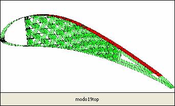
16 Results: Influence of L/R ratio Large node radius facilitates bending deformation of the ligaments, which is a main contributor of overall deformation L/R =.7 L/R =.9 16
17 2 nd CHIRAL-CORE AIRFOIL CONFIGURATION Lift vs. Mach number 2 Lift coefficient 2.5 x 14 Lift L/R =.9 2 L/R =.9 C l L l L/R =.6 1 L/R = M M 17


18 Experimental Validation Static compliance tests L/R =.6 2-y cells L/R =.6 3-y cells Water-jet manufacturing L/R =.94 3-y cells 18
19 Experimental Validation Static compliance tests t 2.54 cm r r = 1.7 cm t =.65 mm.36 m.7 m Out-of-plane thickness = 2. cm t 2.54 cm r r =.67 cm t =.65 mm.36 m.7 m Material: Aluminum 661 T651 E = 71 GPa density = 27 Kg/m 3 ν =.33 r t r =.3 cm t =.65 mm.36 m 2.54 cm Out-of-plane thickness and chord dimensions were chosen given manufacturing restrictions.7 m 19


20 Experimental Validation Static compliance tests Experimental set-up Strain gages Strain-gage locations are chosen based on a preliminary FE analysis LVDT Clamped b.c. Strain gage conditioner and amplifier Vishay Measurement Group 21 System Iotech 2 series acquisition board 2
21 Static compliance tests L/R =.6, 3 unit cells across airfoil thickness Applied load, [N] T.E. disp, [mm] P strain gauge 1 μ ε strain gauge 3 μ ε strain gauge 5 μ ε T.E. disp, [mm] T.E. disp, [mm] T.E. disp, [mm] Four cuts have been used to core and skin compliance strain gauge 2 μ ε strain gauge 4 μ ε strain gauge 6 μ ε T.E. disp, [mm] T.E. disp, [mm] T.E. disp, [mm] 21
22 Static compliance tests L/R =.6, 2 unit cells across airfoil thickness Applied load, [N] T.E. disp, [mm] P strain gauge 1 μ ε strain gauge 3 μ ε strain gauge 5 μ ε T.E. disp, [mm] T.E. disp, [mm] T.E. disp, [mm] strain gauge 2 μ ε strain gauge 4 μ ε T.E. disp, [mm] T.E. disp, [mm] 22
23 Static compliance tests L/R =.6, 2 unit cells across airfoil thickness Non-linear FE models suggest more compliance within elastic range Experimental results Numerical results Applied load, [N] T.E. disp, [mm] 23
24 Static compliance tests L/R =.94, 3 unit cells across airfoil thickness Applied load, [N] T.E. disp, [mm] strain gauge 1 μ ε strain gauge 3 μ ε strain gauge 5 μ ε T.E. disp, [mm] T.E. disp, [mm] T.E. disp, [mm] strain gauge 2 μ ε strain gauge 4 μ ε T.E. disp, [mm] T.E. disp, [mm] 24
25 Static compliance tests Summary Trailing-Edge displacement, [mm] y cells, L/R =.94 2y cells, L/R =.6 3y cells, L/R = Applied Load, [N] The core can be designed to achieve different compliance through a change in a limited number of geometric (L/R); Significant decambering deformations can be sustained within the elastic range of the constitutive material; 25
26 Development of U. of Bristol s chiral airfoil 26
27 Design Constraints Selective Laser Sintering for core manufacturing Maximum core length is.2 m, chord.3 m; Minimum thickness is 1mm for any part of the structure: Ligaments thickness is 1 mm; Opted for solid nodes (nodes are stiff compared to the ligaments) Only a two cell deep core would fit into the aerofoil whilst maintaining a reasonable ligament aspect ratio. It was chosen not to have ligaments attached to the aerofoil skin, to avoid high point loads. A custom chiral core was created, joining only nodes onto the skin and following the curvature of the aerofoil. 27
28 Configuration Skin:.5mm glass fibre composite Flexible but stiff enough to maintain the aerofoil shape and prevent surface buckling. Non-symmetric lay-up [º,9º,+45º,-45º] facilitates conforming to airfoil shape Nose: Stiff, made of pine wood Chiral Honeycomb Core: Material Polyamide Duraform. Design attempts to keep L/r and R/r ratios uniform (uniform E) Node radii (r) are decreased along the chord as the ligament length (L) was constrained by the taper of the aerofoil. - Some of the internal cell angles, θ, differ from 3 - Initial chiral geometry has been used as a guideline. 28 Rubber Strip: Added to induce the chiral rotation(*) (*) Bornengo, D., Scarpa, F., Remillat, C. "Morphing airfoil concept with chiral core structure, IMechE J. Aer. Eng., 25.
29 Numerical analysis Static Analysis: Structural model is coupled with two flow solvers An iterative process was required to achieve convergence of the solution. Ansys FE is used for the structure part; Structural FE model is validated experimentally Flow solvers: Inviscid vortex lattice panel method coded in Matlab, assumes twodimensional (2-D) inviscid flow, and does not consider flow separation. Viscous (XFoil) combines a vortex panel method with a boundary layer model to provide a viscous analysis. It includes boundary layer growth, producing a more realistic pressure distribution, especially at higher angles. 29
30 Example of Results Airfoil tip deflection for increasing velocity, at 15º Inviscid and viscous predictions 3. Graph of Tip Vertical Deflection Against Velocity at an Angle of 15º 2.5 Tip Vertical Deflection (mm) Viscous Inviscid Velocity (m/s) Viscous analysis predicts a much lower deflection: pressure forces acting close to the trailing edge are reduced due to the predicted boundary layer at high angles. 3
31 Analysis of modified Airfoil Effects of: Higher number of cells; Reduction of ligament thickness (.2 mm) and length (6 mm); Changes produce a 2% increase in tip deflection at 8 m/s. Effect of chiral cell density on tip displacement Tip Displacement (mm) Cell Deep 2 Cell Deep Airspeed (m/s) 31

32 Aerodynamic testing: Wind tunnel: Maximum speed ~7m/s. Equipped for lift, drag and pitching moment measurements Visual Measurement Technique: The motion of the aerofoil is tracked by a digital camera system, connected to a laptop for real-time processing. The position of a number of targets can be tracked at a rate of 7.5Hz. Two targets could be used at once to monitor the strains. Wing Prototype 32 Prototype mounted in low turbulence wind tunnel
33 Examples of Results Lift Force against Displacement at Varying Incidence for the Experimental Analysis Deflection vs Speed at varying angles of incidence º EXP 1º EXP 5º EXP Lift (N) º 1º 5º º Deflection (mm) º FEA Vertical Deflection (mm) Speed (m/s) Numerical (FEA) Experimental 33
34 Comments Deflections increase as velocity increases. The relationship is non linear with respect to the lift force on the aerofoil: At low velocities, the rate of increase of deflection is lower than at higher velocities. This could be due to a certain amount of force required to activate the honeycomb deformation mechanism. These forces appear to be different for the varying angles of incidence, This could be explained by the varying pressure distribution around the aerofoil (with respect to angle of incidence), and the anisotropy of the chiral structure (i.e. the main bulk of the pressure force acts on a different area of the aerofoil at different angles, giving a different deflection response). This deflection at 15 incidence corresponds to: Camber change of.3%, A reduction in CL of.5, A reduction of CD of ~.2. Whilst this change is small, it proves that the morphing concept works. 34

35 Comments The measured strains between nodes 19 and 24, and 21 and 22 were found to be positive; Computed values giving a Poisson s ratio of approx e 1 e 2 35

 Wing with continuous variation of L/R")
36 Future developments Aerolastic tailoring through wings with span-wise graded properties L/R Spars with different L/R ratios (Different chord-wise compliance) Wing with continuous variation of L/R ratio L/R 36

37 Related research Dynamic shape control LDS V23 Scanning head (Polytec PSV4 M2) Shaker & F. Transducer 1-lb PCB Piezotronics MATLAB Post- Processing DAQ & Signal processing Polytec PSV-4 M2 37

38 Related research 38


39 Comparison with numerical results ω = 1744 Hz ω = 225 Hz 39


40 Dynamic Shape Control: Motivations Control of boundary layers and flow-separation phenomena; Oscillatory camber concept by D. Munday, J. Jacob and G. Huang Vibrating airfoil skins have been found to produce similar results to synthetic jets [Munday]: postpone stall or airflow separation, reduce pressure drag, reduce wave drag. 4
41 Dynamic Shape Control: Motivations Hogawa H., babinsky H., Evaluation of wave drag reduction by flow control, Aerospace Science and Technology, 1, pp. 1-8, 26 Dynamic deformed shapes could be useful for reducing shock strength and thus wave drag. 41

42 Wave propagation in chiral networks Ω Band-gap structure O A B O k-space position y [m/s] Cg Cg X [m/s] 42
![Related research: Chiral Honeycombs Flat-wise strength Collapse strength per unit weight ( el ) 3/ * / s, [KPa].75.8.85.9.](/docs-images/92/110582379/images/43-1.jpg "95 1 13 12 11 1 9 8 7 6 5 L/R Hexagonal/Auxetic Honeycombs Global Buckling Chiral -3-2 -1 1 2 3, [deg] Thermal behavior")
43 Related research: Chiral Honeycombs Flat-wise strength Collapse strength per unit weight ( el ) 3/ * / s, [KPa] L/R Hexagonal/Auxetic Honeycombs Global Buckling Chiral , [deg] Thermal behavior 43
44 THE END 44
GLOBAL AND LOCAL LINEAR BUCKLING BEHAVIOR OF A CHIRAL CELLULAR STRUCTURE
 GLOBAL AND LOCAL LINEAR BUCKLING BEHAVIOR OF A CHIRAL CELLULAR STRUCTURE Alessandro Spadoni, Massimo Ruzzene School of Aerospace Engineering Georgia Institute of Technology Atlanta, GA 30332 Fabrizio Scarpa
Given the water behaves as shown above, which direction will the cylinder rotate?
 water stream fixed but free to rotate Given the water behaves as shown above, which direction will the cylinder rotate? ) Clockwise 2) Counter-clockwise 3) Not enough information F y U 0 U F x V=0 V=0
CHAPTER 3 ANALYSIS OF NACA 4 SERIES AIRFOILS
 54 CHAPTER 3 ANALYSIS OF NACA 4 SERIES AIRFOILS The baseline characteristics and analysis of NACA 4 series airfoils are presented in this chapter in detail. The correlations for coefficient of lift and
Aeroelastic Gust Response
 Aeroelastic Gust Response Civil Transport Aircraft - xxx Presented By: Fausto Gill Di Vincenzo 04-06-2012 What is Aeroelasticity? Aeroelasticity studies the effect of aerodynamic loads on flexible structures,
PASSIVE MORPHING AIRFOIL WITH HONEYCOMBS. School of Aerospace and Mechanical Engineering, Korea Aerospace University Goyang-City, Republic of Korea
 Proceedings of the ASME 2011 International Mechanical Engineering Conference & Exposition IMECE 2011 November 11-17, 2011, Denver, Colorado, USA IMECE2011-6450 PASSIVE MORPHING AIRFOIL WITH HONEYCOMBS
REPORT DOCUMENTATION PAGE
 REPORT DOCUMENTATION PAGE Form Approved OMB NO. 0704-0188 The public reporting burden for this collection of information is estimated to average 1 hour per response, including the time for reviewing instructions,
Analysis Of Naca 2412 For Automobile Rear Spoiler Using Composite Material *
 Analysis Of Naca 2412 For Automobile Rear Spoiler Using Composite Material * Kamprasad Chodagudi 1, T.b.s Rao 2 -----------------------------------------------------------------------------------------------------------------------------
SPC Aerodynamics Course Assignment Due Date Monday 28 May 2018 at 11:30
 SPC 307 - Aerodynamics Course Assignment Due Date Monday 28 May 2018 at 11:30 1. The maximum velocity at which an aircraft can cruise occurs when the thrust available with the engines operating with the
Computational Fluid Dynamics Study Of Fluid Flow And Aerodynamic Forces On An Airfoil S.Kandwal 1, Dr. S. Singh 2
 Computational Fluid Dynamics Study Of Fluid Flow And Aerodynamic Forces On An Airfoil S.Kandwal 1, Dr. S. Singh 2 1 M. Tech Scholar, 2 Associate Professor Department of Mechanical Engineering, Bipin Tripathi
An Experimental Validation of Numerical Post-Stall Aerodynamic Characteristics of a Wing
 Proceedings of ICTACEM 2017 International Conference on Theoretical, Applied, Computational and Experimental Mechanics December 28-30, 2017, IIT Kharagpur, India ICTACEM-2017/XXXX(paper No.) An Experimental
Optimization Framework for Design of Morphing Wings
 Optimization Framework for Design of Morphing Wings Jian Yang, Raj Nangia & Jonathan Cooper Department of Aerospace Engineering, University of Bristol, UK & John Simpson Fraunhofer IBP, Germany AIAA Aviation
Implementing a Partitioned Algorithm for Fluid-Structure Interaction of Flexible Flapping Wings within Overture
 10 th Symposimum on Overset Composite Grids and Solution Technology, NASA Ames Research Center Moffett Field, California, USA 1 Implementing a Partitioned Algorithm for Fluid-Structure Interaction of Flexible
Mestrado Integrado em Engenharia Mecânica Aerodynamics 1 st Semester 2012/13
 Mestrado Integrado em Engenharia Mecânica Aerodynamics 1 st Semester 212/13 Exam 2ª época, 2 February 213 Name : Time : 8: Number: Duration : 3 hours 1 st Part : No textbooks/notes allowed 2 nd Part :
Wind Tunnel Experiments of Stall Flutter with Structural Nonlinearity
 Wind Tunnel Experiments of Stall Flutter with Structural Nonlinearity Ahmad Faris R.Razaami School of Aerospace Engineering, Universiti Sains Malaysia, Penang, MALAYSIA Norizham Abdul Razak School of Aerospace
Explicit algebraic Reynolds stress models for internal flows
 5. Double Circular Arc (DCA) cascade blade flow, problem statement The second test case deals with a DCA compressor cascade, which is considered a severe challenge for the CFD codes, due to the presence
Given a stream function for a cylinder in a uniform flow with circulation: a) Sketch the flow pattern in terms of streamlines.
 Sketch the flow pattern in terms of streamlines.") Question Given a stream function for a cylinder in a uniform flow with circulation: R Γ r ψ = U r sinθ + ln r π R a) Sketch the flow pattern in terms of streamlines. b) Derive an expression for the angular
Question Given a stream function for a cylinder in a uniform flow with circulation: R Γ r ψ = U r sinθ + ln r π R a) Sketch the flow pattern in terms of streamlines. b) Derive an expression for the angular
Effect of Geometric Uncertainties on the Aerodynamic Characteristic of Offshore Wind Turbine Blades
 the Aerodynamic Offshore Wind, Henning Schmitt, Jörg R. Seume The Science of Making Torque from Wind 2012 October 9-11, 2012 Oldenburg, Germany 1. Motivation and 2. 3. 4. 5. Conclusions and Slide 2 / 12
PRINCIPLES OF FLIGHT
 1 Considering a positive cambered aerofoil, the pitching moment when Cl=0 is: A infinite B positive (nose-up). C negative (nose-down). D equal to zero. 2 The angle between the aeroplane longitudinal axis
CHAPTER 4 OPTIMIZATION OF COEFFICIENT OF LIFT, DRAG AND POWER - AN ITERATIVE APPROACH
 82 CHAPTER 4 OPTIMIZATION OF COEFFICIENT OF LIFT, DRAG AND POWER - AN ITERATIVE APPROACH The coefficient of lift, drag and power for wind turbine rotor is optimized using an iterative approach. The coefficient
Air Loads. Airfoil Geometry. Upper surface. Lower surface
 AE1 Jha Loads-1 Air Loads Airfoil Geometry z LE circle (radius) Chord line Upper surface thickness Zt camber Zc Zl Zu Lower surface TE thickness Camber line line joining the midpoints between upper and
AE 714 Aeroelastic Effects in Structures Term Project (Revised Version 20/05/2009) Flutter Analysis of a Tapered Wing Using Assumed Modes Method
 Flutter Analysis of a Tapered Wing Using Assumed Modes Method") AE 714 Aeroelastic Effects in Structures Term Project (Revised Version 20/05/2009) Flutter Analysis of a Tapered Wing Using Assumed Modes Method Project Description In this project, you will perform classical
AE 714 Aeroelastic Effects in Structures Term Project (Revised Version 20/05/2009) Flutter Analysis of a Tapered Wing Using Assumed Modes Method Project Description In this project, you will perform classical
Aerodynamics. High-Lift Devices
 High-Lift Devices Devices to increase the lift coefficient by geometry changes (camber and/or chord) and/or boundary-layer control (avoid flow separation - Flaps, trailing edge devices - Slats, leading
Experimental Modal Analysis of a Flat Plate Subjected To Vibration
 American Journal of Engineering Research (AJER) 2016 American Journal of Engineering Research (AJER) e-issn: 2320-0847 p-issn : 2320-0936 Volume-5, Issue-6, pp-30-37 www.ajer.org Research Paper Open Access
Some effects of large blade deflections on aeroelastic stability
 47th AIAA Aerospace Sciences Meeting Including The New Horizons Forum and Aerospace Exposition 5-8 January 29, Orlando, Florida AIAA 29-839 Some effects of large blade deflections on aeroelastic stability
Airframe Structural Modeling and Design Optimization
 Airframe Structural Modeling and Design Optimization Ramana V. Grandhi Distinguished Professor Department of Mechanical and Materials Engineering Wright State University VIM/ITRI Relevance Computational
Aeroelastic Analysis of Engine Nacelle Strake Considering Geometric Nonlinear Behavior
 Aeroelastic Analysis of Engine Nacelle Strake Considering Geometric Nonlinear Behavior N. Manoj Abstract The aeroelastic behavior of engine nacelle strake when subjected to unsteady aerodynamic flows is
Introduction to Aeronautics
 Introduction to Aeronautics ARO 101 Sections 03 & 04 Sep 30, 2015 thru Dec 9, 2015 Instructor: Raymond A. Hudson Week #8 Lecture Material 1 Topics For Week #8 Airfoil Geometry & Nomenclature Identify the
Structural Analysis of Wind Turbine Blades
 Structural Analysis of Wind Turbine Blades 2 nd Supergen Wind Educational Seminar Manchester 04 Mar 2009 Paul Bonnet Geoff Dutton Energy Research Unit Rutherford Appleton Laboratory STFC [1] Approach [2]
Contents. I Introduction 1. Preface. xiii
 Contents Preface xiii I Introduction 1 1 Continuous matter 3 1.1 Molecules................................ 4 1.2 The continuum approximation.................... 6 1.3 Newtonian mechanics.........................
Fig. 1. Circular fiber and interphase between the fiber and the matrix.
 Finite element unit cell model based on ABAQUS for fiber reinforced composites Tian Tang Composites Manufacturing & Simulation Center, Purdue University West Lafayette, IN 47906 1. Problem Statement In
FINITE ELEMENT ANALYSIS OF EFFECTIVE MECHANICAL PROPERTIES, VIBRATION AND ACOUSTIC PERFORMANCE OF AUXETIC CHIRAL CORE SANDWICH STRUCTURES
 Clemson University TigerPrints All Theses Theses 8-2013 FINITE ELEMENT ANALYSIS OF EFFECTIVE MECHANICAL PROPERTIES, VIBRATION AND ACOUSTIC PERFORMANCE OF AUXETIC CHIRAL CORE SANDWICH STRUCTURES Hrishikesh
FREQUENCY DOMAIN FLUTTER ANALYSIS OF AIRCRAFT WING IN SUBSONIC FLOW
 FREQUENCY DOMAIN FLUTTER ANALYSIS OF AIRCRAFT WING IN SUBSONIC FLOW Ms.K.Niranjana 1, Mr.A.Daniel Antony 2 1 UG Student, Department of Aerospace Engineering, Karunya University, (India) 2 Assistant professor,
Unsteady flow over flexible wings at different low Reynolds numbers
 EPJ Web of Conferences 114, 02030 (2016) DOI: 10.1051/ epjconf/ 2016114 02030 C Owned by the authors, published by EDP Sciences, 2016 Unsteady flow over flexible wings at different low Reynolds numbers
Multistable Tape-Spring Assemblies for Morphing Aerofoil Applications
 19 th International Conference on Adaptive Structures and Technologies October 6-9, 2008 Ascona, Switzerland ultistable Tape-Spring Assemblies for orphing Aerofoil Applications S. Daynes 1 *, K. D. Potter
Numerical study of battle damaged two-dimensional wings
 Advances in Fluid Mechanics IX 141 Numerical study of battle damaged two-dimensional wings S. Djellal, T. Azzam, M. Djellab & K. Lakkaichi Fluid Mechanics Laboratory Polytechnical School Bordj El Bahri,
( ) (where v = pr ) v V
 (where v = pr ) v V") Problem # The DOF idealized wing whose cross-section is shown in Figure. has leading edge and trailing edge control surfaces. There is no initial angle of attack when the two control surfaces are undeflected.
Problem # The DOF idealized wing whose cross-section is shown in Figure. has leading edge and trailing edge control surfaces. There is no initial angle of attack when the two control surfaces are undeflected.
Numerical Study on Performance of Curved Wind Turbine Blade for Loads Reduction
 Numerical Study on Performance of Curved Wind Turbine Blade for Loads Reduction T. Maggio F. Grasso D.P. Coiro 13th International Conference Wind Engineering (ICWE13), 10-15 July 011, Amsterdam, the Netherlands.
ENGN 2340 Final Project Report. Optimization of Mechanical Isotropy of Soft Network Material
 ENGN 2340 Final Project Report Optimization of Mechanical Isotropy of Soft Network Material Enrui Zhang 12/15/2017 1. Introduction of the Problem This project deals with the stress-strain response of a
Structural-acoustic optimization of 2-D Gradient Auxetic Sandwich Panels
 : 2 nd Euro-Mediterranean Conference 25-27 Apr 2017 on Structural Dynamics and Vibroacoustics Sevilla (Spain) Structural-acoustic optimization of 2-D Gradient Auxetic Sandwich Panels Mohammad Sadegh Mazloomi
Finite Element Method
 Finite Element Method Finite Element Method (ENGC 6321) Syllabus Objectives Understand the basic theory of the FEM Know the behaviour and usage of each type of elements covered in this course one dimensional
Introduction to Aerospace Engineering
 4. Basic Fluid (Aero) Dynamics Introduction to Aerospace Engineering Here, we will try and look at a few basic ideas from the complicated field of fluid dynamics. The general area includes studies of incompressible,
Massachusetts Institute of Technology Department of Aeronautics and Astronautics Cambridge, MA Problem Set 14
 Massachusetts Institute of Technology Department of Aeronautics and Astronautics Cambridge, MA 02139 16.01/16.02 Unified Engineering I, II Fall 2003 Problem Set 14 Name: Due Date: 12/9/03 F18 F19 F20 M19
Part 3. Stability and Transition
 Part 3 Stability and Transition 281 Overview T. Cebeci 1 Recent interest in the reduction of drag of underwater vehicles and aircraft components has rekindled research in the area of stability and transition.
Mechanics of Flight. Warren F. Phillips. John Wiley & Sons, Inc. Professor Mechanical and Aerospace Engineering Utah State University WILEY
 Mechanics of Flight Warren F. Phillips Professor Mechanical and Aerospace Engineering Utah State University WILEY John Wiley & Sons, Inc. CONTENTS Preface Acknowledgments xi xiii 1. Overview of Aerodynamics
A beam reduction method for wing aeroelastic design optimisation with detailed stress constraints
 A beam reduction method for wing aeroelastic design optimisation with detailed stress constraints O. Stodieck, J. E. Cooper, S. A. Neild, M. H. Lowenberg University of Bristol N.L. Iorga Airbus Operations
Syllabus for AE3610, Aerodynamics I
 Syllabus for AE3610, Aerodynamics I Current Catalog Data: AE 3610 Aerodynamics I Credit: 4 hours A study of incompressible aerodynamics of flight vehicles with emphasis on combined application of theory
DEPARTMENT OF AEROSPACE ENGINEERING, IIT MADRAS M.Tech. Curriculum
 DEPARTMENT OF AEROSPACE ENGINEERING, IIT MADRAS M.Tech. Curriculum SEMESTER I AS5010 Engg. Aerodyn. & Flt. Mech. 3 0 0 3 AS5020 Elements of Gas Dyn. & Propln. 3 0 0 3 AS5030 Aircraft and Aerospace Structures
Masters in Mechanical Engineering Aerodynamics 1 st Semester 2015/16
 Masters in Mechanical Engineering Aerodynamics st Semester 05/6 Exam st season, 8 January 06 Name : Time : 8:30 Number: Duration : 3 hours st Part : No textbooks/notes allowed nd Part : Textbooks allowed
Detailed Outline, M E 320 Fluid Flow, Spring Semester 2015
 Detailed Outline, M E 320 Fluid Flow, Spring Semester 2015 I. Introduction (Chapters 1 and 2) A. What is Fluid Mechanics? 1. What is a fluid? 2. What is mechanics? B. Classification of Fluid Flows 1. Viscous
Drag Computation (1)
") Drag Computation (1) Why drag so concerned Its effects on aircraft performances On the Concorde, one count drag increase ( C D =.0001) requires two passengers, out of the 90 ~ 100 passenger capacity, be
Drag Computation (1) Why drag so concerned Its effects on aircraft performances On the Concorde, one count drag increase ( C D =.0001) requires two passengers, out of the 90 ~ 100 passenger capacity, be
Fluid-Structure Interaction Problems using SU2 and External Finite-Element Solvers
 Fluid-Structure Interaction Problems using SU2 and External Finite-Element Solvers R. Sanchez 1, D. Thomas 2, R. Palacios 1, V. Terrapon 2 1 Department of Aeronautics, Imperial College London 2 Department
Aerodynamic Resonance in Transonic Airfoil Flow. J. Nitzsche, R. H. M. Giepman. Institute of Aeroelasticity, German Aerospace Center (DLR), Göttingen
, Göttingen") Aerodynamic Resonance in Transonic Airfoil Flow J. Nitzsche, R. H. M. Giepman Institute of Aeroelasticity, German Aerospace Center (DLR), Göttingen Source: A. Šoda, PhD thesis, 2006 Slide 2/39 Introduction
Aerodynamic Resonance in Transonic Airfoil Flow J. Nitzsche, R. H. M. Giepman Institute of Aeroelasticity, German Aerospace Center (DLR), Göttingen Source: A. Šoda, PhD thesis, 2006 Slide 2/39 Introduction
AEROSPACE ENGINEERING DEPARTMENT. Second Year - Second Term ( ) Fluid Mechanics & Gas Dynamics
 Fluid Mechanics & Gas Dynamics") AEROSPACE ENGINEERING DEPARTMENT Second Year - Second Term (2008-2009) Fluid Mechanics & Gas Dynamics Similitude,Dimensional Analysis &Modeling (1) [7.2R*] Some common variables in fluid mechanics include:
AEROSPACE ENGINEERING DEPARTMENT Second Year - Second Term (2008-2009) Fluid Mechanics & Gas Dynamics Similitude,Dimensional Analysis &Modeling (1) [7.2R*] Some common variables in fluid mechanics include:
THE ANALYSIS OF LAMINATE LAY-UP EFFECT ON THE FLUTTER SPEED OF COMPOSITE STABILIZERS
 THE ANALYSIS OF LAMINATE LAY-UP EFFECT ON THE FLUTTER SPEED OF COMPOSITE STABILIZERS Mirko DINULOVIĆ*, Boško RAŠUO* and Branimir KRSTIĆ** * University of Belgrade, Faculty of Mechanical Engineering, **
CFD COMPUTATION OF THE GROUND EFFECT ON AIRPLANE WITH HIGH ASPECT RATIO WING
 28 TH INTERNATIONAL CONGRESS OF THE AERONAUTICAL SCIENCES CFD COMPUTATION OF THE GROUND EFFECT ON AIRPLANE WITH HIGH ASPECT RATIO WING Sun Tae Kim*, Youngtae Kim**, Tae Kyu Reu* *Agency for Defense Development,
Aerodynamic Rotor Model for Unsteady Flow and Wake Impact
 Aerodynamic Rotor Model for Unsteady Flow and Wake Impact N. Bampalas, J. M. R. Graham Department of Aeronautics, Imperial College London, Prince Consort Road, London, SW7 2AZ June 28 1 (Steady Kutta condition)
Prediction of Propeller Blade Stress Distribution Through FEA
 Research Article Prediction of Propeller Blade Stress Distribution Through FEA Kiam Beng Yeo, Wai Heng Choong and Wen Yen Hau ABSTRACT The Finite Element Analysis (FEA) of marine propeller blade stress
1. Fluid Dynamics Around Airfoils
 1. Fluid Dynamics Around Airfoils Two-dimensional flow around a streamlined shape Foces on an airfoil Distribution of pressue coefficient over an airfoil The variation of the lift coefficient with the
COMPUTATIONAL SIMULATION OF THE FLOW PAST AN AIRFOIL FOR AN UNMANNED AERIAL VEHICLE
 COMPUTATIONAL SIMULATION OF THE FLOW PAST AN AIRFOIL FOR AN UNMANNED AERIAL VEHICLE L. Velázquez-Araque 1 and J. Nožička 2 1 Division of Thermal fluids, Department of Mechanical Engineering, National University
ME 475 Modal Analysis of a Tapered Beam
 ME 475 Modal Analysis of a Tapered Beam Objectives: 1. To find the natural frequencies and mode shapes of a tapered beam using FEA.. To compare the FE solution to analytical solutions of the vibratory
The future of non-linear modelling of aeroelastic gust interaction
 The future of non-linear modelling of aeroelastic gust interaction C. J. A. Wales, C. Valente, R. G. Cook, A. L. Gaitonde, D. P. Jones, J. E. Cooper University of Bristol AVIATION, 25 29 June 2018 Hyatt
Analysis of the high Reynolds number 2D tests on a wind turbine airfoil performed at two different wind tunnels
 Analysis of the high Reynolds number 2D tests on a wind turbine airfoil performed at two different wind tunnels O.Pires 1, X.Munduate 2, O.Ceyhan 3, M.Jacobs 4, J.Madsen 5 1 National Renewable Energy Centre
Aeroelastic Wind Tunnel Testing of Very Flexible High-Aspect-Ratio Wings
 Aeroelastic Wind Tunnel Testing of Very Flexible High-Aspect-Ratio Wings Justin Jaworski Workshop on Recent Advances in Aeroelasticity, Experiment and Theory July 2, 2010 Problem and Scope High altitude
Active Control of Separated Cascade Flow
 Chapter 5 Active Control of Separated Cascade Flow In this chapter, the possibility of active control using a synthetic jet applied to an unconventional axial stator-rotor arrangement is investigated.
1. Tasks of designing
 1 Lecture #18(14) Designing calculation of cross section of a highly aspect ratio wing Plan: 1 Tass of designing Distribution of shear force between wing spars Computation of the elastic center 4 Distribution
Mechanics of Materials II. Chapter III. A review of the fundamental formulation of stress, strain, and deflection
 Mechanics of Materials II Chapter III A review of the fundamental formulation of stress, strain, and deflection Outline Introduction Assumtions and limitations Axial loading Torsion of circular shafts
Review Lecture. AE1108-II: Aerospace Mechanics of Materials. Dr. Calvin Rans Dr. Sofia Teixeira De Freitas
 Review Lecture AE1108-II: Aerospace Mechanics of Materials Dr. Calvin Rans Dr. Sofia Teixeira De Freitas Aerospace Structures & Materials Faculty of Aerospace Engineering Analysis of an Engineering System
STRUCTURAL PROPERTIES OF HELICOPTER ROTOR BLADE SECTIONS
 STRUCTURAL PROPERTIES OF HELICOPTER ROTOR BLADE SECTIONS Graham F.J. Hill and Paul M. Weaver Department of Aerospace Engineering, Queen s Building, University of Bristol, Bristol, England, UK, BS8 1TR
Mechanics of Irregular Honeycomb Structures
 Mechanics of Irregular Honeycomb Structures S. Adhikari 1, T. Mukhopadhyay 1 Chair of Aerospace Engineering, College of Engineering, Swansea University, Singleton Park, Swansea SA2 8PP, UK Sixth International
Mechanics of Inflatable Fabric Beams
 Copyright c 2008 ICCES ICCES, vol.5, no.2, pp.93-98 Mechanics of Inflatable Fabric Beams C. Wielgosz 1,J.C.Thomas 1,A.LeVan 1 Summary In this paper we present a summary of the behaviour of inflatable fabric
Simulation of Aeroelastic System with Aerodynamic Nonlinearity
 Simulation of Aeroelastic System with Aerodynamic Nonlinearity Muhamad Khairil Hafizi Mohd Zorkipli School of Aerospace Engineering, Universiti Sains Malaysia, Penang, MALAYSIA Norizham Abdul Razak School
EE C245 ME C218 Introduction to MEMS Design
 EE C245 ME C218 Introduction to MEMS Design Fall 2007 Prof. Clark T.-C. Nguyen Dept. of Electrical Engineering & Computer Sciences University of California at Berkeley Berkeley, CA 94720 Lecture 16: Energy
Module 4 : Deflection of Structures Lecture 4 : Strain Energy Method
 Module 4 : Deflection of Structures Lecture 4 : Strain Energy Method Objectives In this course you will learn the following Deflection by strain energy method. Evaluation of strain energy in member under
Composite Structures- Modeling, FEA, Optimization and Diagnostics
 Composite Structures- Modeling, FEA, Optimization and Diagnostics Ratan Jha Mechanical and Aeronautical Engineering Clarkson University, Potsdam, NY Composite Laminate Modeling Refined Higher Order Displacement
AEROSPACE ENGINEERING
 AEROSPACE ENGINEERING Subject Code: AE Course Structure Sections/Units Topics Section A Engineering Mathematics Topics (Core) 1 Linear Algebra 2 Calculus 3 Differential Equations 1 Fourier Series Topics
A RESEARCH ON NONLINEAR STABILITY AND FAILURE OF THIN- WALLED COMPOSITE COLUMNS WITH OPEN CROSS-SECTION
 A RESEARCH ON NONLINEAR STABILITY AND FAILURE OF THIN- WALLED COMPOSITE COLUMNS WITH OPEN CROSS-SECTION H. Debski a*, J. Bienias b, P. Jakubczak b a Faculty of Mechanical Engineering, Department of Machine
University of Bristol - Explore Bristol Research. Peer reviewed version. Link to published version (if available): /6.
: /6.") Castellani, M., Cooper, J. E., & Lemmens, Y. (216). Nonlinear Static Aeroelasticity of High Aspect Ratio Wing Aircraft by FEM and Multibody Methods. In 15th Dynamics Specialists Conference [(AIAA 216-1573]
Castellani, M., Cooper, J. E., & Lemmens, Y. (216). Nonlinear Static Aeroelasticity of High Aspect Ratio Wing Aircraft by FEM and Multibody Methods. In 15th Dynamics Specialists Conference [(AIAA 216-1573]
Drag (2) Induced Drag Friction Drag Form Drag Wave Drag
 Induced Drag Friction Drag Form Drag Wave Drag") Drag () Induced Drag Friction Drag Form Drag Wave Drag Outline Nomenclature and Concepts Farfield Drag Analysis Induced Drag Multiple Lifting Surfaces Zero Lift Drag :Friction and Form Drag Supersonic
Drag () Induced Drag Friction Drag Form Drag Wave Drag Outline Nomenclature and Concepts Farfield Drag Analysis Induced Drag Multiple Lifting Surfaces Zero Lift Drag :Friction and Form Drag Supersonic
PES Institute of Technology
 PES Institute of Technology Bangalore south campus, Bangalore-5460100 Department of Mechanical Engineering Faculty name : Madhu M Date: 29/06/2012 SEM : 3 rd A SEC Subject : MECHANICS OF MATERIALS Subject
A Balance for Measurement of Yaw, Lift and Drag on a Model in a Hypersonic Shock Tunnel
 , July 6-8, 2011, London, U.K. A Balance for Measurement of Yaw, Lift and Drag on a Model in a Hypersonic Shock Tunnel S. Trivedi, and V. Menezes Abstract This paper describes the design of an accelerometer
Stability and Control Some Characteristics of Lifting Surfaces, and Pitch-Moments
 Stability and Control Some Characteristics of Lifting Surfaces, and Pitch-Moments The lifting surfaces of a vehicle generally include the wings, the horizontal and vertical tail, and other surfaces such
Chapter 5 Wing design - selection of wing parameters 2 Lecture 20 Topics
 Chapter 5 Wing design - selection of wing parameters Lecture 0 Topics 5..4 Effects of geometric parameters, Reynolds number and roughness on aerodynamic characteristics of airfoils 5..5 Choice of airfoil
AE Stability and Control of Aerospace Vehicles
 AE 430 - Stability and ontrol of Aerospace Vehicles Static/Dynamic Stability Longitudinal Static Stability Static Stability We begin ith the concept of Equilibrium (Trim). Equilibrium is a state of an
Mechanical Engineering for Renewable Energy Systems. Dr. Digby Symons. Wind Turbine Blade Design
 ENGINEERING TRIPOS PART IB PAPER 8 ELECTIVE () Mechanical Engineering for Renewable Energy Systems Dr. Digby Symons Wind Turbine Blade Design Student Handout CONTENTS 1 Introduction... 3 Wind Turbine Blade
Blade Element Momentum Theory
 Blade Element Theory has a number of assumptions. The biggest (and worst) assumption is that the inflow is uniform. In reality, the inflow is non-uniform. It may be shown that uniform inflow yields the
Analysis of a Casted Control Surface using Bi-Linear Kinematic Hardening
 Analysis of a Casted Control Surface using Bi-Linear Kinematic Hardening Abdul Manan Haroon A. Baluch AERO, P.O Box 91, Wah Cantt. 47040 Pakistan Abstract Control Surfaces or Fins are very essential parts
Shafts: Torsion of Circular Shafts Reading: Crandall, Dahl and Lardner 6.2, 6.3
 M9 Shafts: Torsion of Circular Shafts Reading: Crandall, Dahl and Lardner 6., 6.3 A shaft is a structural member which is long and slender and subject to a torque (moment) acting about its long axis. We
Iterative Learning Control for Smart Rotors in Wind turbines First Results
 Iterative Learning Control for Smart Rotors in Wind turbines First Results Owen Tutty 1, Mark Blackwell 2, Eric Rogers 3, Richard Sandberg 1 1 Engineering and the Environment University of Southampton
STRUCTURAL ANALYSIS OF A WESTFALL 2800 MIXER, BETA = 0.8 GFS R1. By Kimbal A. Hall, PE. Submitted to: WESTFALL MANUFACTURING COMPANY
 STRUCTURAL ANALYSIS OF A WESTFALL 2800 MIXER, BETA = 0.8 GFS-411519-1R1 By Kimbal A. Hall, PE Submitted to: WESTFALL MANUFACTURING COMPANY OCTOBER 2011 ALDEN RESEARCH LABORATORY, INC. 30 Shrewsbury Street
JEPPIAAR ENGINEERING COLLEGE
 JEPPIAAR ENGINEERING COLLEGE Jeppiaar Nagar, Rajiv Gandhi Salai 600 119 DEPARTMENT OFMECHANICAL ENGINEERING QUESTION BANK VI SEMESTER ME6603 FINITE ELEMENT ANALYSIS Regulation 013 SUBJECT YEAR /SEM: III
Example 3.7 Consider the undeformed configuration of a solid as shown in Figure 3.60.
 162 3. The linear 3-D elasticity mathematical model The 3-D elasticity model is of great importance, since it is our highest order hierarchical model assuming linear elastic behavior. Therefore, it provides
CHAPTER THREE SYMMETRIC BENDING OF CIRCLE PLATES
 CHAPTER THREE SYMMETRIC BENDING OF CIRCLE PLATES * Governing equations in beam and plate bending ** Solution by superposition 1.1 From Beam Bending to Plate Bending 1.2 Governing Equations For Symmetric
Flight Vehicle Terminology
 Flight Vehicle Terminology 1.0 Axes Systems There are 3 axes systems which can be used in Aeronautics, Aerodynamics & Flight Mechanics: Ground Axes G(x 0, y 0, z 0 ) Body Axes G(x, y, z) Aerodynamic Axes
INSTITUTE OF AERONAUTICAL ENGINEERING (Autonomous) Dundigal, Hyderabad
 Dundigal, Hyderabad") INSTITUTE OF AERONAUTICAL ENGINEERING (Autonomous) Dundigal, Hyderabad - 500 043 AERONAUTICAL ENGINEERING TUTORIAL QUESTION BANK Course Name : LOW SPEED AERODYNAMICS Course Code : AAE004 Regulation : IARE
INSTITUTE OF AERONAUTICAL ENGINEERING (Autonomous) Dundigal, Hyderabad - 500 043 AERONAUTICAL ENGINEERING TUTORIAL QUESTION BANK Course Name : LOW SPEED AERODYNAMICS Course Code : AAE004 Regulation : IARE
1.105 Solid Mechanics Laboratory Fall 2003
 1.105 Solid Mechanics Laboratory Fall 200 Experiment 7 Elastic Buckling. The objectives of this experiment are To study the failure of a truss structure due to local buckling of a compression member. To
Symmetric Bending of Beams
 Symmetric Bending of Beams beam is any long structural member on which loads act perpendicular to the longitudinal axis. Learning objectives Understand the theory, its limitations and its applications
Finite Element Method for Turbomachinery Flows
 SOCRATES Teaching Staff Mobility Program 2000-2001 DMA-URLS Finite Element Method for Turbomachinery Flows Numerical studies on axial flow fan rotor aerodynamics Alessandro Corsini Dipartimento di Meccanica
Static Aeroelasticity Considerations in Aerodynamic Adaptation of Wings for Low Drag
 ABSTRACT EDWARD NICHOLAS SHIPLEY, JUNIOR. Static Aeroelasticity Considerations in Aerodynamic Adaptation of Wings for Low Drag. (Under the direction of Dr. Ashok Gopalarathnam.) This thesis presents a
Consider a wing of finite span with an elliptic circulation distribution:
 Question 1 (a) onsider a wing of finite span with an elliptic circulation distribution: Γ( y) Γo y + b = 1, - s y s where s=b/ denotes the wing semi-span. Use this equation, in conjunction with the Kutta-Joukowsky
D : SOLID MECHANICS. Q. 1 Q. 9 carry one mark each.
 GTE 2016 Q. 1 Q. 9 carry one mark each. D : SOLID MECHNICS Q.1 single degree of freedom vibrating system has mass of 5 kg, stiffness of 500 N/m and damping coefficient of 100 N-s/m. To make the system