Report of Preliminary Geotechnical Investigation for Ponds
|
|
|
- Morgan Waters
- 5 years ago
- Views:
Transcription

1 Florida Department of TRANSPORTATION Report of Preliminary Geotechnical Investigation for Ponds Malabar Road (SR 514) PD&E Study From East of Babcock Street (SR 507) to US 1 Brevard County, Florida FPID: ETDM: The environmental review, consultation, and other actions required by applicable federal environmental laws for this project are being, or have been, carried out by the Florida Department of Transportation (FDOT) pursuant to 23 U.S.C. 327 and a Memorandum of Understanding (MOU) dated December 14, 2016 and executed by the Federal Highway Administration and FDOT. October
2
3 TABLE OF CONTENTS 1.0 SITE AND PROJECT DESCRIPTION REVIEW OF AVAILABLE INFORMATION USGS Quadrangle Map NRCS Soil Survey Review Geology/Hydrology Potentiometric Surface SUBSURFACE EXPLORATION Manual Auger Borings Groundwater Measurement LABORATORY TESTING DESCRIPTION OF SUBSURFACE CONDITIONS Pond Auger Boring Results Groundwater Levels PRELIMINARY GEOTECHNICAL RECOMMENDATIONS Stormwater Ponds USE OF THIS REPORT... 9 APPENDIX Figure 1: USGS Quadrangle and NRCS Soil Survey Maps Figures 2-4: Boring Location Plan Figure 5: Pond Soil Survey Result Sheet Figure 6: Pond Boring Results Table 5: Table 6: Summary of Laboratory Test Results Summary of Groundwater Tables and Permeability Results GEC Project No. 3491G ii Report of Preliminary Geotechnical Engineering Investigation for Ponds SR 514 PD&E Study
4 1.0 SITE AND PROJECT DESCRIPTION This Report of Preliminary Geotechnical Investigation for Ponds has been prepared as a part of the SR 514 Project Development and Environment (PD&E) Study. The PD&E Study is being performed for the proposed improvements of SR 514 from SR 507 (Babcock Street) to US 1. SR 514 currently consists of a two-lane undivided highway with 12-foot lanes and 4-foot shoulders between SR 507 and US 1. The PD&E study will analyze alternatives for widening SR 514 from a two-lane facility to a fourlane facility to address future capacity needs. The project includes the evaluation of 20 potential pond alternative sites. The pond alternatives are located in areas that consist of commercial services, wet prairies, vegetated non-forested wetlands, mixed rangeland, pine flatwoods, unimproved pastures, wet pinelands hydric pine, field crops, institutional, other light industry, disturbed land, woodland pastures, and medium density residential developments. The majority of the pond alternatives are located within undeveloped, vegetated land. The project study area is shown on a United States Geological Society (USGS) Quadrangle Map and the United States Department of Agriculture (USDA) National Resource Conservation Services (NRCS) Soil Survey Map provided on Figure REVIEW OF AVAILABLE INFORMATION GEC reviewed available data including the USGS Quadrangle map and USDA NRCS Soil Survey map to obtain information on soil and groundwater conditions along the proposed alignment. The results of our review are presented in the following report sections. 2.1 USGS Quadrangle Map The pond alternatives are depicted on the USGS Grant and Melbourne, Florida Quadrangle maps shown on Figure 1. Review of the USGS Quadrangle maps indicate that the natural ground surface elevation along the alignment and at the pond alternatives range from approximately +20 feet NGVD to +30 feet NGVD. 2.2 NRCS Soil Survey Review The Natural Resources Conservation Service (NRCS) (formerly SCS) Soil Survey of Brevard County, Florida was reviewed for near-surface soil and groundwater information at the site. The NRCS Soil GEC Project No. 3491G 1 Report of Preliminary Geotechnical Engineering Investigation for Ponds SR 514 PD&E Study
5 Survey map of the site vicinity is shown on Figure 1 in the Appendix. The NRCS soil units at the project site are summarized in Table 1 below: Table 1 Brevard County NRCS Soil Survey Review Unit No. Soil Name 2 Anclote sand, depressional 3 6 Anclote sand, frequently flooded Basinger sand, depressional 7 Basinger sand 15 Cocoa sand 17 EauGallie sand 20 Riviera Winder Depth (inches) Soil Description Unified Classification Symbol AASHTO Classification Symbol 0-19 Sand SP, SP-SM A Sand, Fine sand, loamy fine SP-SM, SP A-3 sand 0-19 Sand SP, SP-SM A Sand, Fine sand, loamy fine SP-SM, SP A-3 sand Depth to Seasonal High Groundwater (feet) Sand, Fine sand SP, SP-SM A Sand SP A Sand, fine sand SP-SM, SP A-2-4, A Sand SP-SM A Loamy sand, sand, loamy fine SM, SP-SM A-2-4 sand Unweathered bedrock Sand, fine sand SP, SP-SM A Sand, fine sand SM, SP-SM A-3, A Sand, fine sand SP, SP-SM A Sandy clay loam, sandy loam, SM, SC, A-2-4 fine sandy loam SC-SM Loamy sand, sand, sandy SM, SC-SM A-2-4 loam 0-30 Sand SP, SP-SM A Sandy loam, sandy clay loam SC-SM, SM, A-2-4 SC Sandy loam, sand, loamy fine SM, SC-SM A-3, A-2-4 sand 0-12 Loamy sand SM A Sandy loam, loamy sand, fine SM A-2-4 sandy loam Sandy clay loam SC, SC-SM A-6, A > GEC Project No. 3491G 2 Report of Preliminary Geotechnical Engineering Investigation for Ponds SR 514 PD&E Study
6 Unit No. Soil Name 28 Immokalee sand 36 Myakka sand 38 Myakka sand, depressional 40 Oldsmar sand 43 Paola fine sand, 0 to 5 percent slopes 49 Pomello sand St. Johns sand, depressional St. Lucie fine sand, 0 to 5 percent slopes 67 Tomoka muck, undrained Depth (inches) Soil Description Unified Classification Symbol AASHTO Classification Symbol 0-33 Sand SP-SM, SP A Sand SM, SP-SM A-3, A Sand SP, SP-SM A Sand Sand Sand SP, SP-SM SM, SP-SM SP, SP-SM A-3 A-2-4, A-3 A Sand SP, SP-SM A Sand SM, SP-SM A-2, A Sand SP, SP-SM A Sand SP-SM, SP A Sand, fine sand SM, SP-SM A-3, A Sandy clay loam, sandy loam SC, SC-SM A-2 Depth to Seasonal High Groundwater (feet) Fine sand, sand SP A-3 > Sand SP-SM, SP A Sand SM, SP-SM A-3, A Sand SP, SP-SM A Sand SP, SP-SM A Sand SM, SP-SM A-2, A Sand SP, SP-SM A Fine sand SP A Muck PT A Sand, loamy sand SP-SM, SP A Sandy clay loam, sandy loam SC, SC-SM, A-2 SM Sandy loam, sandy clay loam SM, SC-SM A Based on review of the NRCS soil survey map, the vast majority of soils within the area of the selected alternative ponds are characterized as sands with variable silt content (A-3, A-2-4). For the majority of the soils within the pond footprints the soil survey lists seasonal high water table levels ranging from 0 to 3.5 feet below the existing ground surface. However, the estimated seasonal high groundwater levels do not account for changes in groundwater due to development and are only relevant for the soil s natural, undisturbed condition. GEC Project No. 3491G 3 Report of Preliminary Geotechnical Engineering Investigation for Ponds SR 514 PD&E Study
7 Information contained in the NRCS Soil Survey should be considered general and may be outdated. Therefore, it may not be reflective of actual soil and groundwater conditions, particularly if recent development in the site vicinity has modified soil conditions or surface/subsurface drainage. The information obtained from the soil borings presented in this report should be considered a more current and accurate characterization of actual site conditions. 2.3 Geology/Hydrology Geologic conditions in this area of Brevard County can generally be described in terms of three basic sedimentary layers. The upper layer is primarily comprised of sands containing varying amounts of silt and clay. These sands are underlain by a layer of clay, clayey sand, phosphate and limestone which is locally referred to as the Hawthorn formation. The third layer underlies the Hawthorn formation and is comprised of limestone. The thickness of these three strata varies throughout Brevard County. In general, the surficial sands typically extend to depths of 40 to 70 feet, while the Hawthorn formation ranges from nearly absent in some locations to thicknesses greater than 100 feet. The groundwater hydrogeology can be described in terms of the nature and relationship of the three basic geologic strata. The near-surface sand stratum is fairly permeable and comprises the water table (unconfined) aquifer. The limestone formation, known as the Floridan aquifer, is highly permeable due to the presence of large interconnected channels and cavities throughout the rock. The Floridan aquifer is the primary source of drinking water in Central Florida. These two permeable strata are separated by the relatively low permeability clays of the Hawthorn formation. The amount of groundwater flow between the two aquifer systems is dependent on the thickness and consistency of the Hawthorn clay confining beds which, as previously stated, varies widely throughout Brevard County. The geology and hydrogeology described above can be conducive to collapses of the ground surface resulting in circular depressions known as "sinkholes." Sinkholes usually occur due to the downward movement of the near surface sands through openings in the Hawthorn formation into the limestone cavities. This process can be likened to the movement of sand through an hourglass. Sinkholes are most likely to occur in areas where the Hawthorn formation is thin or absent, allowing free downward movement of sands into the limestone. GEC Project No. 3491G 4 Report of Preliminary Geotechnical Engineering Investigation for Ponds SR 514 PD&E Study
8 Groundwater also flows freely from the surficial aquifer into the Floridan aquifer in areas where the Hawthorn formation is thin or breached. This phenomenon is called recharge. Therefore, high recharge areas are typically prone to sinkhole activity. An evaluation of sinkhole risk would include performing deep borings to evaluate the nature and thickness of the surficial sands and Hawthorn formation. No method of geological, geotechnical, or geophysical exploration is known that can accurately predict the occurrence of sinkholes. It is common geotechnical practice in Central Florida to make a qualitative prediction of sinkhole risk on the basis of local geological conditions in the vicinity of a particular site. Based on the U.S. Geological Survey Map entitled Recharge and Discharge Areas of the Floridan Aquifer in the St. Johns River Water Management District and Vicinity, Florida, 1984, the project lies in a known low recharge area and, therefore, we can conclude based solely on this data that it also lies in an area where the relative risk of sinkhole formation is low compared to the overall risk across Brevard County. 2.4 Potentiometric Surface The potentiometric level of the Floridan Aquifer in the vicinity of the project alignment ranges from about +30 to 40 feet NGVD. Ground surface elevations vary approximately between +20 and +30 feet NGVD; therefore, deep excavations may be impacted by artesian flow conditions if underlying confining layer(s) are penetrated during construction. 3.0 SUBSURFACE EXPLORATION In addition to consulting the sources of information previously discussed for regional and sitespecific soils data, GEC conducted a subsurface exploration to evaluate soil and groundwater conditions at the selected pond locations provided to us by Atkins. The subsurface exploration for this study generally consisted of performing two hand auger borings to a maximum depth of 10 feet below the existing ground surface at each of the selected pond locations. Subsurface exploration was performed at the following selected pond alternatives: Pond C Pond F Pond G Pond H Pond M Pond O Pond P Pond Q Pond R Pond T GEC Project No. 3491G 5 Report of Preliminary Geotechnical Engineering Investigation for Ponds SR 514 PD&E Study
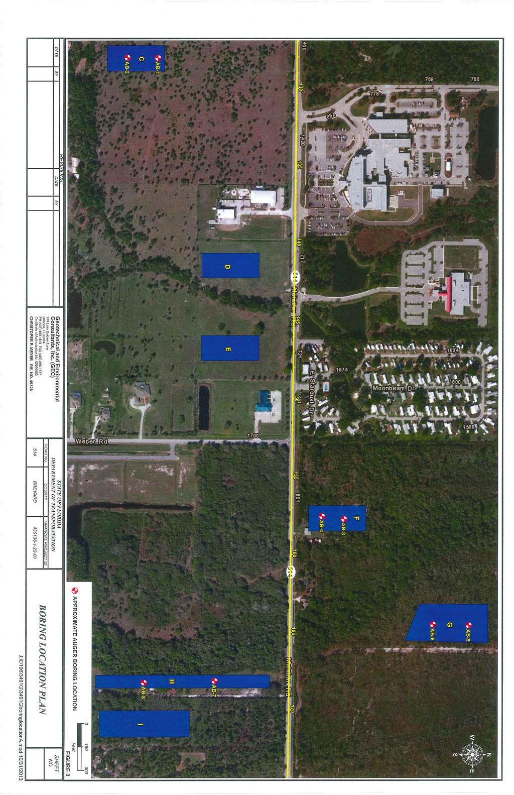
9 The locations of the borings were established at the site by using the aerial plan view and taping distances from existing site features. GEC utilized a hand-held Global Position System (GPS) unit to aid in locating each boring. The boring locations were later surveyed by Atkins in order to obtain ground surface elevations. The approximate boring locations are shown on Figures 2 through Manual Auger Borings Our engineering technician performed standard barrel manual auger borings in general accordance with ASTM D-4700, by manually turning a 3-inch diameter, 6-inch long sampler into the soil until it was full. He then retrieved the sampler and visually examined and classified the soil. This procedure was repeated until the desired termination depth was achieved. A field manual auger boring log was completed by the technician that described the soils penetrated, recorded depth to groundwater, if encountered, and described other details of the boring, methods used, and selected other site conditions at the time of drilling. Our technician collected representative samples for further visual examination and classification in our laboratory. 3.2 Groundwater Measurement A GEC engineering technician measured the depth to the groundwater in the boreholes at the time of drilling and again after approximately 24 hours. Once the groundwater measurements were recorded, the boreholes were backfilled with soil cuttings to prevailing ground surface. 4.0 LABORATORY TESTING Selected soil samples retrieved from the borings were tested in accordance with Florida Standard Testing Methods (FM). Florida Standard Testing Methods are adaptations of recognized standard methods, e.g., ASTM and AASHTO, which have been modified to accommodate Florida s geological conditions. The laboratory testing program for this project is summarized on the following table: Table 2 Summary of Laboratory Testing Program Type of Test Number of Tests Grain size analysis (FM 1 - T88) 11 Percent fine (FM 1 T88) 4 Natural Moisture Content (FM 1-T 265) 8 Organic Content (FM 1-T267) 7 Atterberg limits (FM 1 - T89/90) 1 Laboratory Soil Permeability (FM 1-T215) 6 GEC Project No. 3491G 6 Report of Preliminary Geotechnical Engineering Investigation for Ponds SR 514 PD&E Study
10 The results of our testing are summarized on the Pond Soil Survey Sheet (Figure 5) and the Summary of Laboratory Testing Results (Table 5) in the Appendix. 5.0 DESCRIPTION OF SUBSURFACE CONDITIONS The results of our borings are presented on the Pond Auger Boring Results sheet (Figure 6). The soils encountered in the auger borings were classified using the AASHTO Soil Classification System (A-3, A-2-4, etc.). All soils were described using the ASTM soil descriptions (e.g., sand with silt). GEC based the soil classifications on visual examination and the limited laboratory test results shown on Figure 5. The boring logs indicate subsurface conditions only at the specific boring locations at the time of our field exploration. Subsurface conditions, including groundwater levels, at other locations of the project site may differ from conditions we encountered at the boring locations. Moreover, conditions at the boring locations can change over time. Groundwater levels fluctuate seasonally, and soil conditions can be altered by earthmoving operations. The depths and thicknesses of the subsurface strata indicated on the boring logs were interpolated between samples obtained at different depths in the borings. The actual transition between soil layers may be different than indicated. These stratification lines were used for our analytical purposes and actual earthwork quantities measured during construction should be expected to vary from quantities calculated based on the information in this report. 5.1 Pond Auger Boring Results The soil description and stratum numbers used for the pond auger borings are summarized as follows: Table 3 Soil Stratigraphy Stratum No. Soil Description AASHTO Classification 1 Brown to orange fine sand and fine sand with silt, occasional trace organic material A-3 2 Brown fine sand with silt to silty fine sand A Dark brown mucky fine sand to muck A-8 GEC Project No. 3491G 7 Report of Preliminary Geotechnical Engineering Investigation for Ponds SR 514 PD&E Study
11 The auger borings typically encountered fine sand with varying amounts of silt content (Strata 1 and 2; A-3, A-2-4). In addition, mucky fine sand to muck (Stratum 3; A-8) was encountered in borings AB-2, AB-8, AB-9, AB-11, AB-12, AB-17, and AB-18 at varying depths and thicknesses. Please refer to the Pond Auger Boring Results sheet (Figure 6) for detailed soil and groundwater information at a specific boring location. 5.2 Groundwater Levels Groundwater levels were measured at least 24 hours after completion of the borings. Encountered groundwater elevations at the boring locations ranged from to 19.9 feet NGVD. However, the groundwater table was not encountered to a depth of 10 feet at Borings AB- 19 and AB-20 at Pond T. Groundwater levels can vary seasonally and with changes in subsurface conditions between boring locations. Alterations in surface and/or subsurface drainage brought about by site development can also affect groundwater levels. Therefore, groundwater depths measured at different times or at different locations on the site can be expected to vary from those measured by GEC during this investigation. For purposes of this report, estimated seasonal high groundwater levels are defined as groundwater levels that are anticipated at the end of the wet season during a normal rainfall year under pre-development site conditions. We define a normal rainfall year as a year in which rainfall quantity and distribution were at or near historical averages. We estimate that seasonal high groundwater depths will range from at or above the ground surface, indicated by AGS shown adjacent the boring profile, to greater than 6 feet below ground surface. Our encountered and estimated seasonal high groundwater levels are presented on the Pond Auger Boring Results sheet (Figure 6) and Table 6 in the Appendix. 6.0 PRELIMINARY GEOTECHNICAL RECOMMENDATIONS The preliminary analyses and recommendations contained in this report are based in part on the data obtained from a limited number of soil samples and groundwater measurements obtained from widely-spaced borings. The investigation methods used indicate subsurface conditions only at the specific boring locations, only at the time they were performed, and only to the depths penetrated. Borings cannot be relied upon to accurately reflect the variations that usually exist between boring locations and these variations may not become evident until construction. These recommendations are provided to aid in alignment selection and preliminary construction costs. A final geotechnical engineering evaluation will be required after the alignment, ponds and typical section have been selected. GEC Project No. 3491G 8 Report of Preliminary Geotechnical Engineering Investigation for Ponds SR 514 PD&E Study
12 6.1 Stormwater Ponds The pond borings generally encountered fine sands with varying amounts of silt (A-3, A-2-4) with occasional layers of mucky fine sand to muck (A-8) to the maximum boring termination depth of 10 feet below the existing ground surface. The majority of the soils encountered in the pond borings appear suitable for use as roadway embankment in accordance with Index 505 of the FDOT Standard. Sands excavated below the water table will need to be dried to moisture content near optimum to achieve the required degree of compaction. GEC performed constant head laboratory permeability test on six representative soil samples. The following table summarizes the result of the laboratory permeability tests. Table 4 Summary of Permeability Tests Results Pond No. Boring No. Depth Interval of Soil Sample (ft) Soil Type (AASHTO) Horizontal Permeability, K (ft/day) Pond G AB A Pond H AB A Pond M AB A Pond O AB A Pond Q AB A Pond T AB A Perm Type Lab Perm Constant Head Lab Perm Constant Head Lab Perm Constant Head Lab Perm Constant Head Lab Perm Constant Head Lab Perm Constant Head 7.0 USE OF THIS REPORT GEC has prepared this preliminary report for the exclusive use of Atkins, and FDOT, and for specific application to our client s project. GEC will not be held responsible for any third party s interpretation or use of this report s subsurface data or engineering analysis without our written authorization. The sole purpose of the borings performed by GEC at this site was to obtain indications of subsurface conditions as part of a geotechnical exploration program. GEC has not evaluated the GEC Project No. 3491G 9 Report of Preliminary Geotechnical Engineering Investigation for Ponds SR 514 PD&E Study
13 site for the potential presence of contaminated soil or groundwater, nor have we subjected any soil samples to analysis for contaminants. GEC has strived to provide the services described in this report in a manner consistent with that level of care and skill ordinarily exercised by members of our profession currently practicing in Central Florida. No other representation is made or implied in this document. The preliminary conclusions or recommendations of this report should be disregarded if the nature, design, or location of the facilities is changed. If such changes are contemplated, GEC should be retained to review the new plans to assess the applicability of this report in light of proposed changes. GEC Project No. 3491G 10 Report of Preliminary Geotechnical Engineering Investigation for Ponds SR 514 PD&E Study
14 APPENDIX
15 USGS QUADRANGLE AND NRCS SOIL SURVEY MAPS

16
17 BORING LOCATION PLAN
18

19

20
21 POND SOIL SURVEY RESULT SHEET
22
23 POND BORING RESULTS
24
25 SUMMARY OF LABORATORY TEST RESULTS
26 Table 5 Summary of Laboratory Test Results SR 514 PD&E Study From SR 507 to US 1 FPID No GEC Project No. 3491G Sample Percent Passing by Weight Moisture Atterberg Limits Organic Pond Stratum Boring Depth #10 #40 #60 #100 #200 Content Liquid Plasticity Content AASHTO Number Number Number (feet) Sieve Sieve Sieve Sieve Sieve (%) Limit Index (%) Class. F 1 AB A-3 F 1 AB A-3 G 1 AB A-3 H 1 AB A-3 O 1 AB A-3 Q 1 AB A-3 P 1 AB A-3 T 1 AB A-3 C 2 AB A-2-4 C 3 AB A-8 H 3 AB A-8 M 3 AB A-8 O 3 AB A-8 O 3 AB A-8 R 3 AB A-8
27 SUMMARY OF GROUNDWATER TABLES AND PERMEABILITY RESULTS
28 Pond No. Boring No. Date of Groundwater Measurement Table 6 Summary of Groundwater Tables and Permeability Results SR 514 PD&E From SR 507 to US 1 FPID No GEC Project No. 3491G Ground Surface Elevation (ft NGVD) Encountered Groundwater Depth (feet) Encountered Groundwater Elevation (ft NGVD) Estimated Seasonal High Groundwater Depth (feet) Estimated Seasonal High Groundwater Elevation (ft NGVD) NRCS Soil Survey Seasonal High Groundwater Depth Range (feet) Lab Permeability Test Results Horizontal Permeability Rate (ft/day) Pond C AB-1 08/29/ AB-2 08/29/ AB-3 08/29/ Pond F AB-4 08/29/ AB-5 08/30/ A-3 Pond G > 6.0 AB-6 08/30/ AB-7 08/30/ A-3 Pond H AB-8 08/30/ Pond M AB-9 08/29/ A-8 AB-10 08/29/ AB-11 09/03/ Pond O AB-12 09/03/ A-3 AB-13 09/03/ Pond Q AB-14 09/03/ A-3 AB-15 09/03/ Pond P AB-16 09/03/ AB-17 09/04/ AGS AGS Pond R AB-18 09/04/ AGS AGS AB-19 08/30/ GNE Pond T > 6.0 AB-20 08/30/ GNE A-3 Notes: GNE - Groundwater not encountered below 10 feet of the ground surface AGS - At or Above Ground Surface Soil Type
TIERRA. Florida License No Florida License No
 March 9, 208 TIERRA AECOM 7650 West Courtney Campbell Cswy Tampa, FL 33607 Attn: RE: Mr. Edgar Figueroa, P.E. Geotechnical Engineering Services Report Purchase Order No.: 9532 AECOM Project Number: 6055499
B-1 BORE LOCATION PLAN. EXHIBIT Drawn By: 115G BROOKS VETERINARY CLINIC CITY BASE LANDING AND GOLIAD ROAD SAN ANTONIO, TEXAS.
 N B-1 SYMBOLS: Exploratory Boring Location Project Mngr: BORE LOCATION PLAN Project No. GK EXHIBIT Drawn By: 115G1063.02 GK Scale: Checked By: 1045 Central Parkway North, Suite 103 San Antonio, Texas 78232
Report of Preliminary Geotechnical Exploration. CSO-012 Sewer Separation Cincinnati, Hamilton County, Ohio. February, 2011
 11242843_GeoTech_Preliminary - Feburary 2011_1/40 Report of Preliminary Geotechnical Exploration CSO-012 Sewer Separation Cincinnati, Hamilton County, Ohio February, 2011 11242843_GeoTech_Preliminary -
Ardaman & Associates, Inc. Geotechnical, Environmental and Materials Consultants
 SUBSURFACE SOIL EXPLORATION 42-INCH FORCE MAIN REPLACEMENT CHIQUITA BOULEVARD S AND SW 34 TH STREET CAPE CORAL, LEE COUNTY, FLORIDA Ardaman & Associates, Inc. Geotechnical, Environmental and Materials
An Introduction to Field Explorations for Foundations
 An Introduction to Field Explorations for Foundations J. Paul Guyer, P.E., R.A. Paul Guyer is a registered mechanical engineer, civil engineer, fire protection engineer and architect with over 35 years
Ardaman & Associates, Inc. Geotechnical, Environmental and Materials Consultants
 SUBSURFACE SOIL EXPLORATION DRAINAGE IMPROVEMENTS TO THE HENDRY COUNTY, FLORIDA Ardaman & Associates, Inc. Geotechnical, Environmental and Materials Consultants OFFICES Orlando, 88 S. Orange Avenue, Orlando,
Depth (ft) USCS Soil Description TOPSOIL & FOREST DUFF
 USCS Soil Description TOPSOIL & FOREST DUFF") Test Pit No. TP-6 Location: Latitude 47.543003, Longitude -121.980441 Approximate Ground Surface Elevation: 1,132 feet Depth (ft) USCS Soil Description 0 1.5 1.5 5.0 SM 5.0 8.0 SM Loose to medium dense,
Test Pit No. TP-6 Location: Latitude 47.543003, Longitude -121.980441 Approximate Ground Surface Elevation: 1,132 feet Depth (ft) USCS Soil Description 0 1.5 1.5 5.0 SM 5.0 8.0 SM Loose to medium dense,
Field Exploration. March 31, J-U-B ENGINEERS, Inc. 115 Northstar Avenue Twin Falls, Idaho Attn: Mr. Tracy Ahrens, P. E. E:
 March 31, 201 11 Northstar Avenue 83301 Attn: Mr. Tracy Ahrens, P. E. E: taa@jub.com Re: Geotechnical Data Report Preliminary Phase 1 Field Exploration Revision No. 1 Proposed Rapid Infiltration Basin
Hydrogeological Assessment for Part of Lots 2 and 3, Concession 5, Township of Thurlow, County of Hastings 1.0 INTRODUCTION. 1.
 February 10,2017 25506400 Ontario Ltd. Foxboro, ON Attention: Brad Newbatt Re: Hydrogeological Assessment for Part of Lots 2 and 3, Concession 5, Township of Thurlow, County of Hastings 1.0 INTRODUCTION
IMAGING OF DEEP SINKHOLES USING THE MULTI-ELECTRODE RESISTIVITY IMPLANT TECHNIQUE (MERIT) CASE STUDIES IN FLORIDA
 CASE STUDIES IN FLORIDA") IMAGING OF DEEP SINKHOLES USING THE MULTI-ELECTRODE RESISTIVITY IMPLANT TECHNIQUE (MERIT) CASE STUDIES IN FLORIDA David Harro The G3 Group, 2509 Success Drive, Suite 1, Odessa, FL 33556, david.harro@geo3group.com
IMAGING OF DEEP SINKHOLES USING THE MULTI-ELECTRODE RESISTIVITY IMPLANT TECHNIQUE (MERIT) CASE STUDIES IN FLORIDA David Harro The G3 Group, 2509 Success Drive, Suite 1, Odessa, FL 33556, david.harro@geo3group.com
Ardaman & Associates, Inc. Geotechnical, Environmental and Materials Consultants
 SUBSURFACE SOIL EXPLORATION ANALYSIS AND RECOMMENDATIONS LELY AREA STORMWATER IMPROVEMENT PROJECT (LASIP) COUNTY BARN ROAD AND WING SOUTH CHANNELS NAPLES, COLLIER CO., FLORIDA Ardaman & Associates, Inc.
Civil Engineering, Surveying and Environmental Consulting WASP0059.ltr.JLS.Mich Ave Bridge Geotech.docx
 2365 Haggerty Road South * Canton, Michigan 48188 P: 734-397-3100 * F: 734-397-3131 * www.manniksmithgroup.com August 29, 2012 Mr. Richard Kent Washtenaw County Parks and Recreation Commission 2330 Platt
Geotechnical Data Report
 Geotechnical Data Report Downtown Greenville Future Conveyance Study December 1, 2015 Terracon Project No. 86155032 Prepared for: Prepared by: Terracon Consultants, Inc. December 1, 2015 561 Mauldin Road
DATA REPORT GEOTECHNICAL INVESTIGATION GALVESTON CRUISE TERMINAL 2 GALVESTON, TEXAS
 DATA REPORT GEOTECHNICAL INVESTIGATION GALVESTON CRUISE TERMINAL 2 GALVESTON, TEXAS SUBMITTED TO PORT OF GALVESTON 123 ROSENBERG AVENUE, 8TH FLOOR GALVESTON, TEXAS 77553 BY HVJ ASSOCIATES, INC. HOUSTON,
Soil Map Polk County, Florida
 Soil Map Polk County, Florida 28 9' 21'' 28 8' 23'' 3113000 3113200 3113400 3113600 3113800 3114000 3114200 3114400 3114600 81 51' 19'' 81 51' 19'' 416000 416000 ± 416200 416200 68 416400 68 416400 7 13
ATTACHMENT A PRELIMINARY GEOTECHNICAL SUMMARY
 ATTACHMENT A PRELIMINARY GEOTECHNICAL SUMMARY Kevin M. Martin, P.E. KMM Geotechnical Consultants, LLC 7 Marshall Road Hampstead, NH 0384 603-489-6 (p)/ 603-489-8 (f)/78-78-4084(m) kevinmartinpe@aol.com
10. GEOTECHNICAL EXPLORATION PROGRAM
 Geotechnical site investigations should be conducted in multiple phases to obtain data for use during the planning and design of the tunnel system. Geotechnical investigations typically are performed in
M E M O R A N D U M. Mr. Jonathan K. Thrasher, P.E., Mr. Ian Kinnear, P.E. (FL) PSI
 PSI") M E M O R A N D U M TO: FROM: Mr. Mark Schilling Gulf Interstate Engineering Mr. Jonathan K. Thrasher, P.E., Mr. Ian Kinnear, P.E. (FL) PSI DATE: November 11, 2014 RE: Summary of Findings Geotechnical
M E M O R A N D U M TO: FROM: Mr. Mark Schilling Gulf Interstate Engineering Mr. Jonathan K. Thrasher, P.E., Mr. Ian Kinnear, P.E. (FL) PSI DATE: November 11, 2014 RE: Summary of Findings Geotechnical
 SOIL CLASSIFICATION CHART COARSE-GRAINED SOILS MORE THAN 50% RETAINED ON NO.200 SIEVE FINE-GRAINED SOILS 50% OR MORE PASSES THE NO.200 SIEVE PRIMARY DIVISIONS GRAVELS MORE THAN 50% OF COARSE FRACTION RETAINED
CITY OF CAPE CORAL NORTH 2 UTILITIES EXTENSION PROJECT CONTRACT 3
 GEOTECHNICAL REPORT CITY OF CAPE CORAL NORTH UTILITIES EXTENSION PROJECT CONTRACT City of Cape Coral Procurement Division Cultural Park Boulevard, nd Floor Cape Coral, FL ISSUED FOR BID VOLUME of GEOTECHNICAL
Solution:Example 1. Example 2. Solution: Example 2. clay. Textural Soil Classification System (USDA) CE353 Soil Mechanics Dr.
 CE353 Soil Mechanics Dr.") CE353 Soil Mechanics CE353 Lecture 5 Geotechnical Engineering Laboratory SOIL CLASSIFICATION Lecture 5 SOIL CLASSIFICATION Dr. Talat A Bader Dr. Talat Bader 2 Requirements of a soil Systems Why do we need
CE353 Soil Mechanics CE353 Lecture 5 Geotechnical Engineering Laboratory SOIL CLASSIFICATION Lecture 5 SOIL CLASSIFICATION Dr. Talat A Bader Dr. Talat Bader 2 Requirements of a soil Systems Why do we need
 Photo 1 - Southerly view across 2700 parking lot toward existing building. Multi-residential building borders western side of property in upper right of view. Photo 2 - Southerly view across 2750 parking
 Project: ITHACA-TOMPKINS REGIONAL AIRPORT EXPANSION Project Location: ITHACA, NY Project Number: 218-34 Key to Soil Symbols and Terms TERMS DESCRIBING CONSISTENCY OR CONDITION COARSE-GRAINED SOILS (major
SUPPLEMENTARY INVESTIGATION AND LABORATORY TESTING Aggregate Resource Evaluation Proposed Bernand Quarry San Diego County, California
 October 3, 2 Mr. Mark San Agustin Project No. 28-- Home Land Investments Document No. -92 2239 Curlew Street San Diego, CA 92 SUBJECT: SUPPLEMENTARY INVESTIGATION AND LABORATORY TESTING Aggregate Resource
INVITATION TO BID CITY OF CAPE CORAL SW 6&7 UTILITIES EXTENSION PROJECT CONTRACT VII CENTRAL AREA 6 AND CENTRAL AREA 8 ITB UT13-02/TM-G
 GEOTECHNICAL REPORT INVITATION TO BID CITY OF CAPE CORAL SW 6&7 UTILITIES EXTENSION PROJECT CONTRACT VII CENTRAL AREA 6 AND CENTRAL AREA 8 ITB UT13-02/TM-G City of Cape Coral Procurement Division 1015
Geotechnical Engineering Report
 Geotechnical Engineering Report Turner Turnpike Widening Bridge B Bridge Crossing: South 257 th West Avenue Creek County, Oklahoma June 1, 2016 Terracon Project No. 04155197 Prepared for: Garver, LLC Tulsa,
Clay Robinson, PhD, CPSS, PG copyright 2009
 Engineering: What's soil got to do with it? Clay Robinson, PhD, CPSS, PG crobinson@wtamu.edu, http://www.wtamu.edu/~crobinson, copyright 2009 Merriam-Webster Online Dictionary soil, noun 1 : firm land
Limited Geotechnical Engineering Evaluation Classroom Additions Albany County Campus Laramie, Wyoming
 Limited Geotechnical Engineering Evaluation Classroom Additions Albany County Campus 2300 Missile Drive, Cheyenne, Wyoming 82001 Phone 307-635-0222 www.stratageotech.com Limited Geotechnical Engineering
Geology and Soils. Technical Memorandum
 Geology and Soils Technical Memorandum TO: FDOT FROM: HDR, Inc. DATE: February 2013 PROJECT: St Johns River Crossing FPID No: 208225-3-21-01 Clay, Duval, and St. Johns Counties; Florida Geology and soils
Procedure for Determining Near-Surface Pollution Sensitivity
 Procedure for Determining Near-Surface Pollution Sensitivity Minnesota Department of Natural Resources Division of Ecological and Water Resources County Geologic Atlas Program March 2014 Version 2.1 I.
Date: April 2, 2014 Project No.: Prepared For: Mr. Adam Kates CLASSIC COMMUNITIES 1068 E. Meadow Circle Palo Alto, California 94303
 City of Newark - 36120 Ruschin Drive Project Draft Initial Study/Mitigated Negative Declaration Appendix C: Geologic Information FirstCarbon Solutions H:\Client (PN-JN)\4554\45540001\ISMND\45540001 36120
Geotechnical Data Report
 Geotechnical Data Report ReWa Solar Farm at Durbin Creek Fountain Inn, South Carolina September 1, 2017 Terracon Project No. 86165043 Prepared for: Renewable Water Resources Greenville, South Carolina
ADDENDUM 1 FISHER SLOUGH RESTORATION PROJECT SKAGIT COUNTY, WASHINGTON
 F I N A L A D D E N D U M 1 R E P O R T ADDENDUM 1 FISHER SLOUGH RESTORATION PROJECT SKAGIT COUNTY, WASHINGTON REPORT OF GEOTECHNICAL INVESTIGATION URS JOB NO. 3376186 Prepared for Tetra Tech Inc. 142
June 9, R. D. Cook, P.Eng. Soils Engineer Special Services Western Region PUBLIC WORKS CANADA WESTERN REGION REPORT ON
 PUBLIC WORKS CANADA WESTERN REGION REPORT ON GEOTECHNICAL INVESTIGATION PROPOSED MARTIN RIVER BRIDGE MILE 306.7 MACKENZIE HIGHWAY Submitted by : R. D. Cook, P.Eng. Soils Engineer Special Services Western
Preliminary Geotechnical Investigation Cadiz / Trigg County I-24 Business Park. Cadiz, Kentucky
 Environmental & Geoscience, LLC 834 Madisonville Road Hopkinsville, KY 440 70.44.000 FAX 70.44.8300 www.wedrill.com A member of Trinity Energy & Infrastructure Group, LLC Preliminary Geotechnical Investigation
APPENDIX E SOILS TEST REPORTS
 Otsego County, NY Site Work Specifications APPENDIX E SOILS TEST REPORTS Blue Wing Services, Inc. July 1, 2010 Blue Wing Services May 20, 2010 Page 2 the site, was not made available to Empire at this
THE MINISTRY OF ENERGY AND ENERGY INDUSTRIES MINERALS DIVISION MINE DESIGN TEMPLATE OPERATOR NAME: OPERATOR ADDRESS: PHONE NUMBER: FACSIMILE:
 THE MINISTRY OF ENERGY AND ENERGY INDUSTRIES MINERALS DIVISION MINE DESIGN TEMPLATE 1.0 GENERAL INFORMATION OPERATOR NAME: OPERATOR ADDRESS: PHONE NUMBER: FACSIMILE: NAME OF CONTACT: CELLULAR PHONE: EMAIL
Hydrogeology of Karst NE Wisconsin. Dr. Maureen A. Muldoon UW-Oshkosh Geology Department
 Hydrogeology of Karst NE Wisconsin Dr. Maureen A. Muldoon UW-Oshkosh Geology Department WI Bedrock Outline Karst Landscapes Existing WQ Data Flow in Karst Aquifers Overview of Silurian Aquifer Water Level
TAMPA BAY TRIBUTARIES BASIN. Hydrogeological Setting
 TAMPA BAY TRIBUTARIES BASIN Hydrogeological Setting Aquifers within the Tampa Bay Tributaries Basins ground water flow system include the Floridan aquifer system, the intermediate aquifer system, and the
ENGINEERING ASSOCIATES
 July 16, 211 Vista Design, Inc. 11634 Worcester Highway Showell, Maryland 21862 Attention: Reference: Dear Mr. Polk: Mr. Richard F. Polk, P.E. Geotechnical Engineering Report Charles County RFP No. 11-9
Northern Colorado Geotech
 PRELIMINARY GEOTECHNICAL ENGINEERING REPORT PROPOSED CECIL FARMS DEVELOPMENT WELD COUNTY ROAD 7, BETWEEN ROADS 7 AND 7 SEVERANCE, COLORADO NORTHERN COLORADO GEOTECH PROJECT NO. 0-6 APRIL 0, 06 Prepared
3.18 GEOLOGY AND SOILS
 3.18 GEOLOGY AND SOILS This section discusses geologic resource concerns as they relate to the environment, public safety, and project design both during construction and after completion of the project.
December 5, Junction Gateway, LLC 7551 W. Sunset Boulevard #203 Los Angeles, CA Mr. James Frost P: Dear Mr.
 December 5, 2014 Junction Gateway, LLC 7551 W. Sunset Boulevard #203 90046 Attn: Re: Mr. James Frost P: 323.883.1800 Geotechnical Update Letter Sunset & Effie Mixed Use Development 4301 to 4311 Sunset
Groundwater Hydrology
 EXERCISE 12 Groundwater Hydrology INTRODUCTION Groundwater is an important component of the hydrologic cycle. It feeds lakes, rivers, wetlands, and reservoirs; it supplies water for domestic, municipal,
Preliminary Geotechnical Evaluation Gooseberry Point Pedestrian Improvements Whatcom County, Washington SITE AND PROJECT DESCRIPTION
 File No. 12-100 Geotechnical & Earthquake Engineering Consultants Mr. Kevin Brown, P.E. Gray & Osborne, Inc. 3710 168 th Street NE, Suite B210 Arlington, Washington 98223 Subject: Draft Report Preliminary
GEOTECHNICAL REPORT. Matanuska-Susitna Borough. Parks Highway Connections Museum Drive. Matanuska-Susitna Borough, Alaska.
 Matanuska-Susitna Borough GEOTECHNICAL REPORT Parks Highway Connections Museum Drive Matanuska-Susitna Borough, Alaska March 2, 20 Prepared By: John Thornley, PE Geotechnical Engineer 333 Arctic Blvd.,
3.0 SUMMARY OF FINDINGS
 AECOM 500 W Jefferson St. Suite 1600 Louisville, KY 40202 www.aecom.com 502-569-2301 tel 502-569-2304 fax October 17, 2018 Big Rivers Electric Corporation Sebree Generating Station 9000 Highway 2096 Robards,
APPENDIX A Geotechnical Report, dated December 2009 PLANT CITY, FLORIDA SYDNEY ROAD RECLAIMED WATER PROJECT INVITATION TO BID ITB NO.
 APPENDIX A Geotechnical Report, dated December 29 PLANT CITY, FLORIDA SYDNEY ROAD RECLAIMED WATER INVITATION TO BID ITB NO. 11-9136-1 ADVERTISED: November, 21 MANDATORY PRE-BID MEETING: November 29, 21
REPORT OF PRELIMINARY GEOTECHNICAL SITE INVESTIGATION KERSHAW COUNTY EXIT 87 OFFICE PARK. ELGIN, SOUTH CAROLINA S&ME Project No.
 REPORT OF PRELIMINARY GEOTECHNICAL SITE INVESTIGATION KERSHAW COUNTY EXIT 87 OFFICE PARK ELGIN, SOUTH CAROLINA S&ME Project No. 1611-04-450 Prepared For: KERSHAW COUNTY ECONOMIC DEVELOPMENT OFFICE Post
Geotechnical Engineering Report
 Geotechnical Engineering Report Turner Turnpike Widening Bridge D Bridge Crossing: South 209 th West Avenue Creek County, Oklahoma June 1, 2016 Terracon Project No. 04155197 Prepared for: Garver, LLC Tulsa,
patersongroup Mineral Aggregate Assessment 3119 Carp Road Ottawa, Ontario Prepared For Mr. Greg LeBlanc March 7, 2014 Report: PH2223-REP.
 Geotechnical Engineering Environmental Engineering group Hydrogeology Geological Engineering Archaeological Studies Materials Testing 3119 Carp Road Prepared For Mr. Greg LeBlanc March 7, 2014 Paterson
Geotechnical Engineering Report
 Geotechnical Engineering Report Turner Turnpike Widening Polecat Creek Bridge (Bridge A) June 1, 2016 Terracon Project No. 04155197 Prepared for: Garver, LLC Prepared by: Terracon Consultants, Inc. TABLE
Pierce County Department of Planning and Land Services Development Engineering Section
 Page 1 of 7 Pierce County Department of Planning and Land Services Development Engineering Section PROJECT NAME: DATE: APPLICATION NO.: PCDE NO.: LANDSLIDE HAZARD AREA (LHA) GEOLOGICAL ASSESSMENT REPORT
Land subsidence due to groundwater withdrawal in Hanoi, Vietnam
 Land Subsidence (Proceedings of the Fifth International Symposium on Land Subsidence, The Hague, October 1995). 1AHS Publ. no. 234, 1995. 55 Land subsidence due to groundwater withdrawal in Hanoi, Vietnam
6.2 Geotechnical Investigation and Construction Material Survey
 6.2 Geotechnical Investigation and Construction Material Survey Geological surveys and investigations were conducted to obtain information on the subsurface geological condition required for the preliminary
Preliminary soil survey of the NATL Old Field Plots
 Preliminary soil survey of the NATL Old Field Plots The preliminary soil survey consisted of completing auger borings at 25 m intervals and included auger borings at total of 46 points. The borings were
Custom Soil Resource Report for Okeechobee County, Florida
 United States Department of Agriculture Natural Resources Conservation Service A product of the National Cooperative Soil Survey, a joint effort of the United States Department of Agriculture and other
PRELIMINARY GEOTECHNICAL REPORT. State College Redevelopment State College Borough, Centre County, Pennsylvania. CMT Laboratories File No.
 PRELIMINARY GEOTECHNICAL REPORT State College Redevelopment State College Borough, Centre County, Pennsylvania CMT Laboratories File No. 1638700 Prepared for: National Development Council One Battery Park
ENCE 3610 Soil Mechanics. Site Exploration and Characterisation Field Exploration Methods
 ENCE 3610 Soil Mechanics Site Exploration and Characterisation Field Exploration Methods Geotechnical Involvement in Project Phases Planning Design Alternatives Preparation of Detailed Plans Final Design
PREPARED FOR MR. JOE WOOD CARTER & SLOOPE, INC PEAKE ROAD MACON, GEORGIA PREPARED BY
 SUBSURFACE EXPLORATION AND GEOTECHNICAL ENGINEERING EVALUATION MACON WATER AUTHORITY (MWA) SANITARY SEWER RELOCATION MACON, GEORGIA GEC PROJECT NO. 14077.2 PREPARED FOR MR. JOE WOOD CARTER & SLOOPE, INC.
NAPLES MUNICIPAL AIRPORT
 NAPLES MUNICIPAL AIRPORT NAPLES MUNICIPAL AIRPORT (APF) TAXIWAY D REALIGNMENT AND DRAINAGE IMPROVEMENTS NORTH QUADRANT ADDENDUM NUMBER TWO March, The following Addendum is hereby made a part of the Plans
GEOTECHNICAL POLICIES AND PROCEDURES MANUAL CHAPTER 5 GEOTECHNICAL INVESTIGATION PLANNING GUIDELINES
 GEOTECHNICAL POLICIES AND PROCEDURES MANUAL CHAPTER 5 GEOTECHNICAL INVESTIGATION PLANNING GUIDELINES GEOTECHNICAL INVESTIGATION PLANNING GUIDELINES 5-i TABLE OF CONTENTS 1. PURPOSE... 1 2. INTRODUCTION...
Geotechnical Engineering Report
 Geotechnical Engineering Report Single-Span Bridge North Western Road & Hall of Fame Avenue August 25, 2015 Terracon Project No. 03155156 Prepared for: Olsson Associates Prepared by: Terracon Consultants,
GEOTECHNICAL ENGINEERING II. Subject Code : 06CV64 Internal Assessment Marks : 25 PART A UNIT 1
 GEOTECHNICAL ENGINEERING II Subject Code : 06CV64 Internal Assessment Marks : 25 PART A UNIT 1 1. SUBSURFACE EXPLORATION 1.1 Importance, Exploration Program 1.2 Methods of exploration, Boring, Sounding
LEGEND ODOT CLASS. A-4b. A-6a. A-6b TOTAL VISUAL WEATHERED SANDSTONE VISUAL BORING LOCATION - PLAN VIEW
 PROJECT THE PROJECT CONSISTS IN PART OF ACING TWO STRUCTURES, EASTBOUND AND WESTBOUND STRUCTURES, RESPECTIVELY FOR THE PROPOSED SR OVER BLUE ROAD (CR 9). THE TWO STRUCTURES AS ANNED, ARE SINGLE-SPAN STRUCTURES
J.H. Campbell Generating Facility Pond A - Location Restriction Certification Report
 J.H. Campbell Generating Facility Pond A - Location Restriction Certification Report Pursuant to: 40 CFR 257.60 40 CFR 257.61 40 CFR 257.62 40 CFR 257.63 40 CFR 257.64 Submitted to: Consumers Energy Company
 R-1 Conveyor Relocation Project Legend 0 500 1000 1500 ft. This map is a user generated static output from an Internet mapping site and is for general reference only. Data layers that appear on this map
REPORT OF SUBSURFACE EXPLORATION
 REPORT OF SUBSURFACE EXPLORATION GRAND RIVER DAM AUTHORITY HULBERT 69 KV SWITCHING STATION S. 440 Road Hulbert, Cherokee County, Oklahoma ENERCON PROJECT NO. GRDA006 MARCH 7, 2012 PREPARED FOR: C/O ENERCON
PRELIMINARY GEOTECHNICAL ENGINEERING REPORT
 PRELIMINARY GEOTECHNICAL ENGINEERING REPORT TOWN OF ASHLAND TOWN HALL 101 THOMPSON STREET ASHLAND, VIRGINIA JOB NUMBER: 39016 PREPARED FOR: PMA PLANNERS & ARCHITECTS 10325 WARWICK BOULEVARD NEWPORT NEWS,
APPENDIX A. Borehole Logs Explanation of Terms and Symbols
 APPENDIX A Borehole Logs Explanation of Terms and Symbols Page 153 of 168 EXPLANATION OF TERMS AND SYMBOLS The terms and symbols used on the borehole logs to summarize the results of field investigation
GEOTECHNICAL INVESTIGATION REPORT
 GEOTECHNICAL INVESTIGATION REPORT SOIL INVESTIGATION REPORT FOR STATIC TEST FACILITY FOR PROPELLANTS AT BDL, IBRAHIMPATNAM. Graphics Designers, M/s Architecture & Engineering 859, Banjara Avenue, Consultancy
16 January 2018 Job Number: RICHARD NEWMAN C\- CLARK FORTUNE MCDONALD AND ASSOCIATES PO BOX 553 QUEENSTOWN
 16 January 2018 Job Number: 50595 RICHARD NEWMAN C\- CLARK FORTUNE MCDONALD AND ASSOCIATES PO BOX 553 QUEENSTOWN CHANSEN@CFMA.CO.NZ STORMWATER DISPOSAL ASSESSMENT Dear Richard, RDAgritech were requested
Finding Large Capacity Groundwater Supplies for Irrigation
 Finding Large Capacity Groundwater Supplies for Irrigation December 14, 2012 Presented by: Michael L. Chapman, Jr., PG Irrigation Well Site Evaluation Background Investigation Identify Hydrogeologic Conditions
3.12 Geology and Topography Affected Environment
 3 Affected Environment and Environmental Consequences 3.12 Geology and Topography 3.12.1 Affected Environment 3.12.1.1 Earthquakes Sterling Highway MP 45 60 Project Draft SEIS The Kenai Peninsula is predisposed
STRUCTURAL STABILITY ASSESSMENT
 STRUCTURAL STABILITY ASSESSMENT CFR 257.73(d) Bottom Ash Pond Complex Cardinal Plant Brilliant, Ohio October, 2016 Prepared for: Cardinal Operating Company Cardinal Plant Brilliant, Ohio Prepared by: Geotechnical
Correlation of unified and AASHTO soil classification systems for soils classification
 Journal of Earth Sciences and Geotechnical Engineering, vol. 8, no. 1, 2018, 39-50 ISSN: 1792-9040 (print version), 1792-9660 (online) Scienpress Ltd, 2018 Correlation of unified and AASHTO classification
Exhibit RMP-4. Foote Creek Geology and Topography
 Exhibit RMP-4 Foote Creek Geology and Topography Memorandum To: From: CC: Travis Brown, PacifiCorp Daria Drago, P.E., PMP Dr. Deb Luchsinger Date: January 9, 2019 Re: Foote Creek Rim 1 - Geologic Conditions
CENTRAL REGION GEOHAZARDS RISK ASSESSMENT SITE INSPECTION FORM
 SITE NUMBER AND NAME C55 H861:02 Slide LEGAL DESCRIPTION NW 14-40-14-W4 CENTRAL REGION GEOHAZARDS RISK ASSESSMENT SITE INSPECTION FORM HIGHWAY & KM NAD 83 COORDINATES N 5811217 E 437291 PREVIOUS INSPECTION
Geotechnical Engineering Report
 Geotechnical Engineering Report Richland Creek Trunk Sewer Greenville, South Carolina March 31, 2014 Terracon Project No. 86145008 Prepared for: Renewable Water Resources Greenville, South Carolina Prepared
Hydric Rating by Map Unit Harrison County, Mississippi 30 27' 27'' 30 26' 57''
 Hydric Rating by Map Unit Harrison County, Mississippi 30 27' 27'' 30 26' 57'' 3370400 3370500 3370600 3370700 3370800 3370900 3371000 3371100 3371200 89 2' 40'' 89 2' 41'' 303700 303700 303800 303800
KDOT Geotechnical Manual Edition. Table of Contents
 KDOT Geotechnical Manual 2007 Edition The KDOT Geotechnical Manual is available two volumes. Both volumes are very large electronic (pdf) files which may take several minutes to download. The table of
SITE INVESTIGATION 1
 SITE INVESTIGATION 1 Definition The process of determining the layers of natural soil deposits that will underlie a proposed structure and their physical properties is generally referred to as site investigation.
The process of determining the layers of natural soil deposits that will underlie a proposed structure and their physical properties is generally
 The process of determining the layers of natural soil deposits that will underlie a proposed structure and their physical properties is generally referred to as sub surface investigation 2 1 For proper
REPORT OF PRELIMINARY GEOTECHNICAL EXPLORATION
 REPORT OF PRELIMINARY GEOTECHNICAL EXPLORATION ENKA INTERMEDIATE SCHOOL Sand Hill Road Candler, North Carolina Prepared For: BUNCOMBE COUNTY SCHOOLS Prepared By: AMEC ENVIRONMENT & INFRASTRUCTURE, INC.
CE 240 Soil Mechanics & Foundations Lecture 3.2. Engineering Classification of Soil (AASHTO and USCS) (Das, Ch. 4)
 (Das, Ch. 4)") CE 240 Soil Mechanics & Foundations Lecture 3.2 Engineering Classification of Soil (AASHTO and USCS) (Das, Ch. 4) Outline of this Lecture 1. Particle distribution and Atterberg Limits 2. Soil classification
CE 240 Soil Mechanics & Foundations Lecture 3.2 Engineering Classification of Soil (AASHTO and USCS) (Das, Ch. 4) Outline of this Lecture 1. Particle distribution and Atterberg Limits 2. Soil classification
APPENDIX C. Borehole Data
 APPENDIX C Borehole Data MAJOR DIVISIONS SOIL CLASSIFICATION CHART SYMBOLS GRAPH LETTER TYPICAL DESCRIPTIONS ADDITIONAL MATERIAL
Geotechnical Subsurface Exploration, Engineering Evaluation and Dam Visual Observation Sun Valley Drive Extension Roswell, Fulton County, GA
 Ranger Consulting, Inc. Geotechnical, Environmental, Drilling, Construction 3147 Martha Berry Highway, Rome, Georgia 165; Phone: 76-29-1782; Fax: 76-29-171 April 2, 215 Mr. Tommy Crochet, PE McGee Partners,
PLATE 6 FEB G r o v e l a n d F l o o d w a l l - B o r e h o l e M a p. Legend. Groveland Floodwall Boreholes. Contour Lines.
 611 6 Defau FALS conto Conto DPLV lt Eurs20 01_to 3po Defau FALS conto Conto DPLV lt Eurs20 01_to 4po 612 Conto DPLV conto Defau FALS 01_to urs20 Elt po 5 Conto DPLV conto Defau FALS 01_to urs15 Elt po
Dashed line indicates the approximate upper limit boundary for natural soils. C L o r O L C H o r O H
 SYMBOL SOURCE 8 9 1 SOIL DATA NATURAL SAMPLE DEPTH WATER PLASTIC LIQUID PLASTICITY NO. CONTENT LIMIT LIMIT INDEX (%) (%) (%) (%) Client: County of Berthoud Project: Project No.: Boring B-2 S-1-5' 6.2 8
Custom Soil Resource Report for Forrest County, Mississippi
 United States Department of Agriculture Natural Resources Conservation Service A product of the National Cooperative Soil Survey, a joint effort of the United States Department of Agriculture and other
Converse Consultants Geotechnical Engineering, Environmental & Groundwater Science, Inspection & Testing Services
 Converse Consultants Geotechnical Engineering, Environmental & Groundwater Science, Inspection & Testing Services Ms. Rebecca Mitchell Mt. San Antonio College Facilities Planning & Management 1100 North
Prediction of subsoil subsidence caused by opencast mining
 Land Subsidence (Proceedings of the Fifth International Symposium on Land Subsidence, The Hague, October 1995). IAHS Publ. no. 234, 1995. 167 Prediction of subsoil subsidence caused by opencast mining
How & Where does infiltration work? Summary of Geologic History Constraints/benefits for different geologic units
 June 26, 2007: Low Impact Development 1 Associated Earth Sciences, Inc. Associated Earth Sciences, Inc. Presented by: Matthew A. Miller, PE April 24, 2012 How & Where does infiltration work? Summary of
Geotechnical Recommendations for Proposed Additions to the Three Mile Creek Severe Weather Attenuation Tank Project
 TECHNICAL MEMORANDUM Geotechnical Recommendations for Proposed Additions to the Three Mile Creek Severe Weather Attenuation Tank Project PREPARED FOR: PREPARED BY: DATE: June 28, 218 PROJECT NUMBER: 697482
Geophysical Methods for Screening and Investigating Utility Waste Landfill Sites in Karst Terrain
 Geophysical Methods for Screening and Investigating Utility Waste Landfill Sites in Karst Terrain Gary Pendergrass, PE, RG, F.NSPE Principal Geological Engineer Kansas City Geotechnical Conference 2017
REPORT NO 12/115/D NOVEMBER 2012 GEOTECHNICAL INVESTIGATION FOR THE PROPOSED SOLAR PHOTOVOLTAIC FACILITY, GROOTVLEI POWER STATION
 Consulting Geotechnical Engineers & Engineering Geologists P.O.Box 3557 Cramerview 2060. Tel: (011) 465-1699. Fax: (011) 465-4586. Cell 082 556 7302 & 076 966 8445 REPORT NO 12/115/D NOVEMBER 2012 GEOTECHNICAL
M E M O R A N D U M. Mr. Jonathan K. Thrasher, P.E. and Mr. Ian Kinnear, P.E. PSI
 M E M O R A N D U M TO: FROM: Mr. Mark Schilling Gulf Interstate Engineering Mr. Jonathan K. Thrasher, P.E. and Mr. Ian Kinnear, P.E. PSI DATE: November 11, 2014 RE: Summary of Findings Geotechnical Study
Proposed Cemetery Thornhill Road. Tier One Hydrogeological Risk Assessment. Peter Mitchell Associates
 Proposed Cemetery Thornhill Road Tier One Hydrogeological Risk Assessment Peter Mitchell Associates January 2015 Executive Summary This report uses a desk-based risk assessment technique published by the
REPORT ON SLOPE STABILITY INVESTIGATION DON MILLS ROAD AND EGLINTON AVENUE EAST TORONTO, ONTARIO. Prepared for:
 REPORT ON SLOPE STABILITY INVESTIGATION DON MILLS ROAD AND EGLINTON AVENUE EAST TORONTO, ONTARIO Prepared for: TORONTO AND REGION CONSERVATION AUTHORITY Prepared By: SIRATI & PARTNERS CONSULTANTS LIMITED
SOIL INVESTIGATION REPORT. PROPOSED HOUSING DEVELOPMENT PROJECT Coral Spring, Trelawny, Jamaica.
 SOIL INVESTIGATION REPORT PROPOSED HOUSING DEVELOPMENT PROJECT Coral Spring, Trelawny, Jamaica. Prepared for: FCS Consultants 7a Barbados Avenue Kingston 5, Jamaica Prepared by: NHL Engineering Limited