APPENDIX E SOILS TEST REPORTS
|
|
|
- Rodger Barrett
- 6 years ago
- Views:
Transcription
1 Otsego County, NY Site Work Specifications APPENDIX E SOILS TEST REPORTS Blue Wing Services, Inc. July 1, 2010
2
3
4 Blue Wing Services May 20, 2010 Page 2 the site, was not made available to Empire at this time, and accordingly is not included in this report. The test borings were made using a Central Mine Equipment model 550X allterrain tire mounted drill rig using hollow stem auger and/or split spoon sampling techniques. Test boring C-1 was advanced in soil to a depth of 52.0 feet below the existing ground surface, where it was subsequently terminated. Test boring C-2 was advanced in soil to a depth of 20.0 feet and terminated. At test boring location C-1, split spoon samples and Standard Penetration Tests (SPTs) were taken continuously from the ground surface to a depth of 40 feet, and then in standard intervals of 5 feet or less until the boring was terminated at 52 feet. At test boring location C-2, split spoon samples and SPTs were taken in standard intervals of 5 feet or less, from the ground surface until the boring was terminated. The split spoon sampling and SPTs were completed in general accordance with ASTM D Standard Test Method for Penetration Test and Split-Barrel Sampling of Soils. A geologist from SJB prepared the test boring logs based on visual observation of the recovered soil samples and review of the driller s field notes. The soil samples were described based on visual/manual estimation of the grain size distribution, along with characteristics such as color, relative density, consistency, moisture, etc. The test boring logs are presented in Attachment A, along with general information and a key of terms and symbols used to prepare the logs. SUBSURFACE CONDITIONS At test boring location C-1, fill soil consisting of brown-black sandy clayey silt was encountered at the ground surface and found to extend a depth of about 2 feet Beneath the fill at this location, and from the surface of boring C-2, indigenous soils were encountered which consist of predominately brown and brown-gray loose to firm sand and gravel deposits, containing varying amounts of silt. These soils were found to extend to the depths explored at the two boring locations. The SPT N values obtained in these soils ranged from 4 to 29, indicating their relative density is loose to firm. Bedrock was not encountered within the depths explored by the test borings. Freestanding water was present in boring C-1 at a depth of 38.3 feet at completion of drilling. Freestanding water was not apparent within test boring C-2 following the completion of drilling/soil sampling. It is possible that groundwater might not have had sufficient time to accumulate/stabilize in the boreholes within the time that had elapsed from the completion of drilling and the time of measurement.
5 Blue Wing Services May 20, 2010 Page 3 A loose, moist to wet sand soil zone was present in boring C-1 at a depth of about 13 to 19 feet, suggesting that some localized groundwater may be trapped or perched at that location and depth. It should be expected that groundwater conditions could vary with location and with changes in soil conditions, precipitation and seasonal conditions. GEOTECHNICAL EVALUATION AND RECOMMENDATIONS General Based on the subsurface conditions encountered in the test borings, it is recommended that the proposed communication tower foundations (i.e. spread foundations) bear in the relatively firm gravel and sand soil stratum between a depth of 5 feet and 9 feet. A relatively loose soil zone was encountered in boring C-1 between a depth of about 11 feet and 20 feet and should be avoided as the foundation bearing zone. Spread Foundation Design As stated above the spread foundations for supporting the tower structure, should bear on the firm gravel and sand soil stratum between a depth of 5 feet and 9 feet. The spread foundations can be sized based on a maximum net allowable bearing pressure of 3,000 pounds per square foot (psf). However, if the foundations would need to bear deeper than 9 feet, then further evaluation by Empire along with a reduced net allowable bearing capacity will be necessary. Isolated footings, with pedestals extending to the surface, should be at least 4 feet in width. In all cases a minimum embedment of 4 feet below final grades should be maintained for frost protection. It is estimated that the spread foundation, which are sized and constructed in accordance with our recommendations will undergo total settlement of around ¾- inch or less. Resistance to Lateral and Uplift Loads The tower foundations should be designed for a factor of safety of 1.5 (F.S.=1.5) against movement, under transient lateral and uplift loading conditions.
6 Blue Wing Services May 20, 2010 Page 4 Passive lateral soil resistance, for spread foundations, which are backfilled using a Structural Fill, as recommended below, can be computed based on a passive earth pressure coefficient (K p ) of 3.2, along with a moist soil unit weight of 130 pounds per cubic foot (pcf) and a submerged soil unit weight of 65 pcf. In addition to the passive soil resistance, sliding resistance can be computed based on a bedrock subgrade/foundation interface friction factor of Uplift design, for spread foundations, should be based on the uplift resistance of the backfill soils and the foundation structure. The weight of the soil column above the foundation, extending out at a maximum angle of 20 degrees, from the vertical line above the edge of the footing, can be added to the weight of the foundation when computing the uplift resistance. The weight of the soil column may be computed based on a moist soil unit weight of 130 pcf and a submerged soil unit weight of 65 pcf, provided the backfill is a Structural Fill, which is placed and compacted in accordance with our recommendations below. For design purposes, we recommend that temporary perched groundwater conditions be assumed at a depth of 5 feet below the ground surface. Accordingly, submerged (i.e. buoyant) soil unit weights should be used for computing both the soil passive earth pressure and uplift resistance below a depth of 5 feet. Seismic Design Criteria Based on the subsurface conditions encountered in the test borings, it is Empire s opinion that the upper 100 feet of the site should be classified as Seismic Site Class D in accordance with the criteria presented on Table of the Building Code of New York State (dated August 2007). The spectral accelerations for the project site were obtained by Empire from the United States Geological Survey (USGS) web site ( These accelerations are based on 2003 NEHRP mapping, as published in the Building Code of NYS, dated August 2007, and were obtained by using the Zip Code for the Cooperstown, New York area. The spectral response accelerations in the Cooperstown, New York area (Zip Code 13326) for the Seismic Site Class D classifications are as follows: Short Period Response (S MS ) g 1 Second Period Response (S M1 ) g
7 Blue Wing Services May 20, 2010 Page 5 The corresponding five percent damped design spectral response accelerations (S DS and S D1 ) are as follows: S DS g S D g Spread Foundation Construction Construction dewatering should be required for surface water control and for any excavations, which may encounter groundwater seepage. Surface water should be diverted away from open excavations and prevented from accumulating on exposed subgrades. It is possible that some localized trapped or perched groundwater could be present at various times and locations and could be encountered in the excavations, depending on the excavation location, depth, the permeability of the soils encountered and the actual groundwater conditions at the time of construction. It is anticipated that diversion berms, proper site grading, cutoff trenches, and sump and pump methods of dewatering will generally be sufficient to control groundwater conditions. Excavation for the foundations should be performed using methods, which minimize disturbance to the bearing subgrades. All fill, organics, and any soft, loose, wet or otherwise deleterious indigenous soil material, beneath the proposed foundation bearing grades, should be undercut and removed. Following excavation, the prepared soil bearing grades should be observed and evaluated by a representative of Empire. Placement of some compacted Structural Fill beneath the foundation, following observation of the bearing grade, may be desirable to level the bearing grade and provide a working surface for setting the reinforcing and constructing the foundation. After completion of the foundation construction, the foundation excavations should be backfilled as soon as possible and prior to construction of the superstructure. It is recommended that the foundation excavations be backfilled with a Structural Fill as recommended below.
8 Blue Wing Services May 20, 2010 Page 6 Structural Fill Material Structural Fill, which is placed as foundation backfill, should consist of a crusher run stone or crushed gravel and sand, free of clay, organics and friable or deleterious particles. As a minimum, the crusher run stone or crushed gravel and sand should meet the requirements of New York State Department of Transportation, Standard Specifications, Item M Type 4 Subbase, with the condition that if a gravel and sand product is used (vs. a crusher run stone), the gravel should be a crushed gravel material. Accordingly, the Structural Fill should have the following gradation requirements. Sieve Size Percent Finer Distribution by Weight 2 inch 100 ¼ inch No No The Structural Fill should be compacted to a minimum of 95 percent of the maximum dry density as measured by the modified Proctor test (ASTM D1557). Placement of the fill should not exceed a maximum loose lift thickness of 6 to 8 inches. It may be necessary to reduce the loose lift thickness depending on the type of compaction equipment used so that the required density is attained. The Structural Fill should have a moisture content within two percent of its optimum moisture content at the time it is compacted. CONCLUDING REMARKS This report was prepared to assist in the planning and design of the proposed communication tower planned off of 172 County Highway, Route 33 W in Cooperstown, New York. The report has been prepared for the exclusive use of Blue Wing Services and other members of the design team, for specific application to this site and this project only. The investigation program, geotechnical evaluation and recommendations were completed based on Empire Geo-Services, Inc. s understanding of the proposed project, as described herein, and through the application of generally accepted soils and foundation engineering practices. No warranties, expressed or inferred, are made by the conclusions, opinions, recommendations or services provided.
9
10 ATTACHMENT A SUBSURFACE EXPLORATION LOGS
11
12
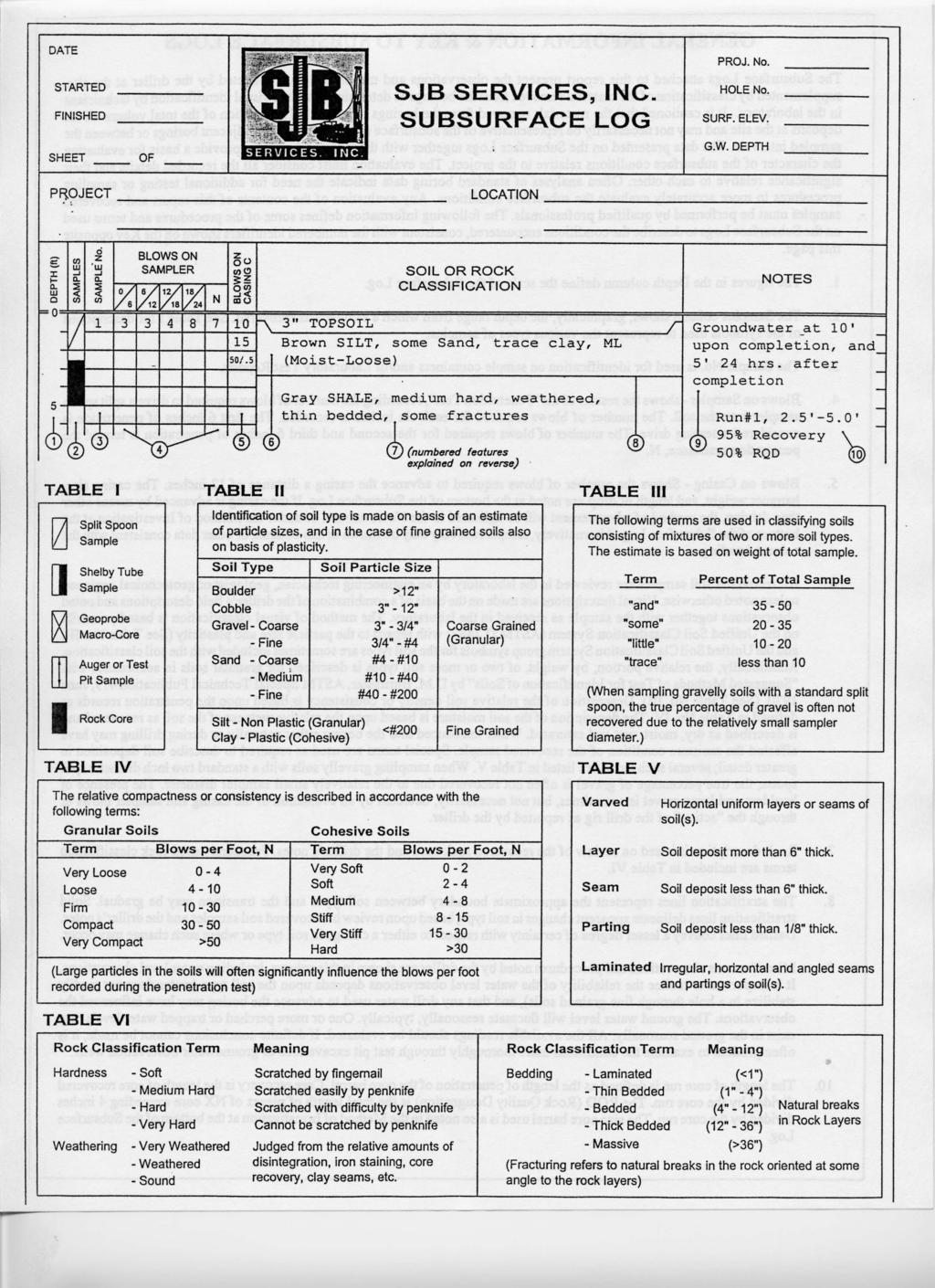
13 DATE START 5/11/2010 SJB SERVICES, INC. HOLE NO. C-1 FINISH 5/11/2010 SUBSURFACE LOG SURF. ELEV SHEET 1 OF 2 G.W. DEPTH See Notes PROJECT: PROPOSED CELL TOWER SITE LOCATION: 172 COUNTY HIGHWAY, ROUTE 33W PROJ. NO.: BE C COOPERSTOWN, NEW YORK DEPTH SMPL BLOWS ON SAMPLER SOIL OR ROCK NOTES FT. NO. 0/6 6/12 12/18 N CLASSIFICATION Brown-Black Clayey SILT, some f-c Sand, tr.gravel (moist, FILL) Brown f-c GRAVEL and f-c Sand, little Silt (moist, firm, GM) (loose) Brown f-c SAND, tr.-little Silt (moist-wet, v.loose, SW) Brown Fine SAND, tr.-little Silt, tr.gravel (moist, firm, SP-SM) (moist-wet, loose) Brown Fine SAND, little-some Silt (moist, firm, SM) Brown-Grey Fine SAND, little Silt, little f-c Gravel (moist, firm, SM) Contains occasional Silt partings and seams Brown Fine SAND, tr.-little Silt (wet, firm, SP-SM) Contains little Silt (SM) No Recovery Sample #7 N = NO. BLOWS TO DRIVE 2-INCH SPOON 12-INCHES WITH A 140 LB. PIN WT. FALLING 30-INCHES PER BLOW CLASSIFIED BY: Geologist DRILLER: K. FULLER DRILL RIG TYPE : CME 550X METHOD OF INVESTIGATION ASTM D-1586 USING HOLLOW STEM AUGERS
14 DATE START 5/11/2010 SJB SERVICES, INC. HOLE NO. C-1 FINISH 5/11/2010 SUBSURFACE LOG SURF. ELEV SHEET 2 OF 2 G.W. DEPTH See Notes PROJECT: PROPOSED CELL TOWER SITE LOCATION: 172 COUNTY HIGHWAY, ROUTE 33W PROJ. NO.: BE C COOPERSTOWN, NEW YORK DEPTH SMPL BLOWS ON SAMPLER SOIL OR ROCK NOTES FT. NO. 0/6 6/12 12/18 N CLASSIFICATION WOH Becomes Brown-Grey (loose) WOH = Weight of Hammer and Rods Boring Complete at 52.0' Free standing water recorded at 38.3' at boring completion. 60 Ground Rod installed at completion N = NO. BLOWS TO DRIVE 2-INCH SPOON 12-INCHES WITH A 140 LB. PIN WT. FALLING 30-INCHES PER BLOW CLASSIFIED BY: Geologist DRILLER: K. FULLER DRILL RIG TYPE : CME 550X METHOD OF INVESTIGATION ASTM D-1586 USING HOLLOW STEM AUGERS
15 DATE START 5/12/2010 SJB SERVICES, INC. HOLE NO. C-2 FINISH 5/12/2010 SUBSURFACE LOG SURF. ELEV SHEET 1 OF 1 G.W. DEPTH See Notes PROJECT: PROPOSED CELL TOWER SITE LOCATION: 172 COUNTY HIGHWAY, ROUTE 33W PROJ. NO.: BE C COOPERSTOWN, NEW YORK DEPTH SMPL BLOWS ON SAMPLER SOIL OR ROCK NOTES FT. NO. 0/6 6/12 12/18 N CLASSIFICATION Brown SILT, little-some fine Sand, tr.gravel (moist, loose, ML) Brown f-c GRAVEL and f-c Sand, little Silt (moist, firm, GM) Brown f-c SAND, some f-c Gravel, little Silt (moist, firm, SM) No Recovery Sample # Brown Fine SAND, little-some Silt (moist, firm, SM) 25 Boring Complete at 20.0' No free standing water encountered at boring completion. Ground Rod installed at completion N = NO. BLOWS TO DRIVE 2-INCH SPOON 12-INCHES WITH A 140 LB. PIN WT. FALLING 30-INCHES PER BLOW CLASSIFIED BY: Geologist DRILLER: K. FULLER DRILL RIG TYPE : CME 550X METHOD OF INVESTIGATION ASTM D-1586 USING HOLLOW STEM AUGERS
16 ATTACHMENT B GEOTECHNICAL REPORT LIMITATIONS
17 GEOTECHNICAL REPORT LIMITATIONS Empire Geo-Services, Inc. (Empire) has endeavored to meet the generally accepted standard of care for the services completed, and in doing so is obliged to advise the geotechnical report user of our report limitations. Empire believes that providing information about the report preparation and limitations is essential to help the user reduce geotechnical-related delays, cost over-runs, and other problems that can develop during the design and construction process. Empire would be pleased to answer any questions regarding the following limitations and use of our report to assist the user in assessing risks and planning for site development and construction. PROJECT SPECIFIC FACTORS: The conclusions and recommendations provided in our geotechnical report were prepared based on project specific factors described in the report, such as size, loading, and intended use of structures; general configuration of structures, roadways, and parking lots; existing and proposed site grading; and any other pertinent project information. Changes to the project details may alter the factors considered in development of the report conclusions and recommendations. Accordingly, Empire cannot accept responsibility for problems which may develop if we are not consulted regarding any changes to the project specific factors that were assumed during the report preparation. SUBSURFACE CONDITIONS: The site exploration investigated subsurface conditions only at discrete test locations. Empire has used judgement to infer subsurface conditions between the discrete test locations, and on this basis the conclusions and recommendations in our geotechnical report were developed. It should be understood that the overall subsurface conditions inferred by Empire may vary from those revealed during construction, and these variations may impact on the assumptions made in developing the report conclusions and recommendations. For this reason, Empire should be retained during construction to confirm that conditions are as expected, and to refine our conclusions and recommendations in the event that conditions are encountered that were not disclosed during the site exploration program. USE OF GEOTECHNICAL REPORT: Unless indicated otherwise, our geotechnical report has been prepared for the use of our client for specific application to the site and project conditions described in the report. Without consulting with Empire, our geotechnical report should not be applied by any party to other sites or for any uses other than those originally intended. CHANGES IN SITE CONDITIONS: Surface and subsurface conditions are subject to change at a project site subsequent to preparation of the geotechnical report. Changes may include, but are not limited to, floods, earthquakes, groundwater fluctuations, and construction activities at the site and/or adjoining properties. Empire should be informed of any such changes to determine if additional investigative and/or evaluation work is warranted. MISINTERPRETATION OF REPORT: The conclusions and recommendations contained in our geotechnical report are subject to misinterpretation. To limit this possibility, Empire should review project plans and specifications relative to geotechnical issues to confirm that the recommendations contained in our report have been properly interpreted and applied. Subsurface exploration logs and other report data are also subject to misinterpretation by others if they are separated from the geotechnical report. This often occurs when copies of logs are given to contractors during the bid preparation process. To minimize the potential for misinterpretation, the subsurface logs should not be separated from our geotechnical report and the use of excerpted or incomplete portions of the report should be avoided. OTHER LIMITATIONS: Geotechnical engineering is less exact than other design disciplines, as it is based partly on judgement and opinion. For this reason, our geotechnical report may include clauses that identify the limits of Empire s responsibility, or that may describe other limitations specific to a project. These clauses are intended to help all parties recognize their responsibilities and to assist them in assessing risks and decision making. Empire would be pleased to discuss these clauses and to answer any questions that may arise.
18
19
20
21
22
23
24
25
26
27

28
29
30
31
32
33
34

35
36
37
38
39
40
41
42

43
44
45
46

47
48
49
50 Blue Wing Services May 20, 2010 Page 2 locations/orientation on the site, was not made available to Empire at this time, and accordingly is not included in this report. The test borings were made using a Central Mine Equipment model 550X allterrain tire mounted drill rig using hollow stem auger and/or split spoon sampling techniques. Both test borings were advanced in soil and weathered shale and sandstone rock to a depth of about 10 feet below the existing ground surface where auger refusal (more competent bedrock refusal) was encountered. Split spoon samples and Standard Penetration Tests (SPTs) were taken continuously from the ground surface to a depth of about 10 feet where auger refusal was met. The split spoon sampling and SPTs were completed in general accordance with ASTM D Standard Test Method for Penetration Test and Split-Barrel Sampling of Soils. The auger refusal material encountered in both test borings was cored using a NQ size double tube core barrel in accordance with ASTM D 2113 Standard Practice for Rock core Drilling and Sampling of Rock for Site Investigation. Fifteen (15) feet and ten (10) feet of the refusal material was cored after reaching auger refusal at boring locations OT-1 and OT-2, respectively. A geologist from SJB prepared the test boring logs based on visual observation of the recovered soil and rock core samples and review of the driller s field notes. The soil samples were described based on visual/manual estimation of the grain size distribution, along with characteristics such as color, relative density, consistency, moisture, etc. The rock core samples were also described, including characteristics such as color, rock type, hardness, weathering, bedding thickness, core recovery and rock quality designation (RQD). The test boring logs are presented in Attachment A, along with general information and a key of terms and symbols used to prepare the logs. SUBSURFACE CONDITIONS Fill soils were not apparent at the surface of either test boring. Accordingly, the indigenous soils, beginning at the ground surface, consisted of a relatively thin upper stratum of red-brown silt and gravely silty sand soil deposits extending to a depth of about 2 feet. These soils are classified as ML and SM group soils using the Unified Soil Classification System (USCS). This stratum is followed by a zone of highly weathered shale and sandstone rock, which extends to a depth about 10 feet and then grades to a more competent Sandstone bedrock, as indicated by the auger refusal and subsequent bedrock cores. The SPT N values obtained in the highly weathered shale and sandstone
51 Blue Wing Services May 20, 2010 Page 3 rock were generally REF (Sample spoon refusal 50 blows or more to advance the sample spoon with less than 6-inches of penetration), indicating this matrix is of a very compact or very hard density/consistency. As mentioned above, auger refusal was encountered in each of the test borings at depths of 10.3 feet and 10.0 feet below the existing site grades. After reaching auger refusal at test boring OT-1 and OT-2, a total of 15 feet and 10 feet of bedrock was cored, respectively. The bedrock was cored in three sections at test boring OT-1 and two sections at OT-2, each section consisting of a five feet long core run. The bedrock encountered at both boring locations consisted of red-brown medium hard, sound, bedded to thickly bedded Sandstone bedrock. Core recoveries ranged from 85% to 100% and the rock quality designation (RQD) values ranged from 65% to 75%, indicating the recovered rock core has a fair rock mass quality. Freestanding water was not apparent within the test borings immediately following the completion of overburden drilling/soil sampling. We note that, groundwater, if present, might not have had sufficient time to accumulate in the boreholes within the time that had elapsed from the completion of drilling and the time of measurement. It should be expected that groundwater conditions could vary with location and with changes in soil conditions, precipitation and seasonal conditions. GEOTECHNICAL EVALUATION AND RECOMMENDATIONS General Based on the subsurface conditions encountered in the test borings, the proposed communication tower can be supported on a spread foundation system bearing within the upper highly weathered shale and sandstone rock encountered at and below a depth of about 2 to 3 feet, or on the underlying more competent Sandstone bedrock, present below a depth of 10 feet. The upper highly weathered shale and sandstone rock appears should be rippable using a large excavator equipped with a rock teeth bucket, although this effort could be difficult in some cases, particularly as the excavation depth in this stratum increases. The underlying more competent Sandstone bedrock most likely will require the use of a hydraulic/pneumatic breaker to loosen the bedrock prior to excavation if the foundation excavations would extend into this material. Accordingly, the Contractor should be prepared to handle such conditions.
52 Blue Wing Services May 20, 2010 Page 4 Spread Foundation Design Spread foundations for supporting the tower structure, should bear on the highly weathered shale and sandstone rock, or on the underlying more competent Sandstone bedrock. The bearing grade surface should be free of all soil and loose rock particles. It may be desirable to level the bearing surface with a lean concrete (f c > 500 psi) mud mat, prior to construction of the foundations. Spread foundations bearing on the upper highly weathered shale and sandstone rock above a depth of 10 feet should be sized based on a maximum net allowable bearing pressure of 5,000 pounds per square foot (psf). Spread foundations bearing on the more competent Sandstone bedrock below a depth of 10 feet can be sized based on a maximum net allowable bearing pressure of 10,000 pounds per square foot (psf). In both cases, isolated footings, with pedestals extending to the surface, should be at least 4 feet in width. In addition a minimum embedment of 4 feet below final grades should be maintained for frost protection. It is estimated that the spread foundation, which are sized and constructed in accordance with our recommendations will undergo total settlement of around ¼- inch or less on the upper highly weathered shale and sandstone rock and insignificant total settlement if bearing on the more competent Sandstone bedrock below a depth of 10 feet. Resistance to Lateral and Uplift Loads The tower foundations should be designed for a factor of safety of 1.5 (F.S.=1.5) against movement, under transient lateral and uplift loading conditions. Passive lateral soil resistance, for spread foundations, which are backfilled using a Structural Fill, as recommended below, can be computed based on a passive earth pressure coefficient (K p ) of 3.2, along with a moist soil unit weight of 130 pounds per cubic foot (pcf) and a submerged soil unit weight of 65 pcf. In addition to the passive soil resistance, sliding resistance can be computed based on a subgrade/foundation interface friction factor of Uplift design, for spread foundations, should be based on the uplift resistance of the backfill soils and the foundation structure. The weight of the soil column above the foundation, extending out at a maximum angle of 20 degrees, from the vertical line above the edge of the footing, can be added to the weight of the foundation when
53 Blue Wing Services May 20, 2010 Page 5 computing the uplift resistance. The weight of the soil column may be computed based on a moist soil unit weight of 130 pcf and a submerged soil unit weight of 65 pcf, provided the backfill is a Structural Fill, which is placed and compacted in accordance with our recommendations below. For design purposes, we recommend that temporary perched groundwater conditions be assumed at a depth of 5 feet below the ground surface. Accordingly, submerged (i.e. buoyant) soil unit weights should be used for computing both the soil passive earth pressure and uplift resistance below a depth of 5 feet. Seismic Design Criteria Based on the subsurface conditions encountered in the test borings, it is Empire s opinion that the upper 100 feet of the site should be classified as Seismic Site Class B in accordance with the criteria presented on Table of the Building Code of New York State (dated August 2007). The spectral accelerations for the project site were obtained by Empire from the United States Geological Survey (USGS) web site ( These accelerations are based on 2003 NEHRP mapping, as published in the Building Code of NYS, dated August 2007, and were obtained by using the Zip Code for the Otego, New York area. The spectral response accelerations in the Otego, New York area (Zip Code 13825) for the Seismic Site Class B classifications are as follows: Short Period Response (S MS ) g 1 Second Period Response (S M1 ) g The corresponding five percent damped design spectral response accelerations (S DS and S D1 ) are as follows: S DS g S D g Spread Foundation Construction Construction dewatering should be required for surface water control and for any excavations, which may encounter groundwater seepage. Surface water should be diverted away from open excavations and prevented from accumulating on
54 Blue Wing Services May 20, 2010 Page 6 exposed subgrades. It is possible that some localized trapped or perched groundwater could be present at various times and locations and could be encountered in the excavations, depending on the excavation location, depth, the permeability of the soils and bedrock encountered and the actual groundwater conditions at the time of construction. It is anticipated that diversion berms, proper site grading, cut-off trenches, and sump and pump methods of dewatering will generally be sufficient to control groundwater conditions. Excavation of the highly weathered shale and sandstone rock and the more competent Sandstone bedrock, should be performed using methods, which minimize disturbance to the foundation bearing grades. All soil and any loose rock material should be removed from the foundation bearing grades. Following excavation, the prepared bearing grades should be observed and evaluated by a representative of Empire. Placement of a lean concrete (f c > 500 psi) mud mat, following observation of the bearing grade may be desirable to level the bearing grade and provide a working surface for setting the reinforcing and constructing the foundation. After completion of the foundation construction, the excavations should be backfilled as soon as possible and prior to construction of the superstructure. It is recommended that the foundation excavations be backfilled with a Structural Fill as recommended below. Structural Fill Material Structural Fill, which is placed as foundation backfill, should consist of a crusher run stone or crushed gravel and sand, free of clay, organics and friable or deleterious particles. As a minimum, the crusher run stone or crushed gravel and sand should meet the requirements of New York State Department of Transportation, Standard Specifications, Item M Type 4 Subbase, with the condition that if a gravel and sand product is used (vs. a crusher run stone), the gravel should be a crushed gravel material. Accordingly, the Structural Fill should have the following gradation requirements. Sieve Size Percent Finer Distribution by Weight 2 inch 100 ¼ inch No No
55
56 ATTACHMENT A SUBSURFACE EXPLORATION LOGS
57

58
59 DATE START 5/12/2010 SJB SERVICES, INC. HOLE NO. OT-1 FINISH 5/12/2010 SUBSURFACE LOG SURF. ELEV SHEET 1 OF 1 G.W. DEPTH See Notes PROJECT: CELL TOWER INVESTIGATION - ROCKDALE LOCATION: 107 DUNCAN LANE PROJ. NO.: BE D OTEGO, NEW YORK DEPTH SMPL BLOWS ON SAMPLER SOIL OR ROCK NOTES FT. NO. 0/6 6/12 12/18 N CLASSIFICATION /0.4 REF /0.4 REF Red-Brown SILT, tr.sand, tr.clay (moist, compact, ML) Red-Brown Highly Weathered SHALE and Sandstone Rock (moist) REF = Sample Spoon Refusal 4 50/0.4 REF /0.3 REF 6 50/0.3 REF Red-Brown SANDSTONE rock, medium hard, sound, bedded to thickly bedded, contains occasional Shale partings and seams NQ '2' Size Rock Core RUN #1: 10.3' ' REC = Approx. 95% RQD - Approx. 70% 20 RUN #2: 15.3' ' REC = Approx. 85% RQD - Approx. 75% 25 RUN #3: 20.3' ' REC = Approx. 90% RQD - Approx. 65% 30 Boring Complete at 25.3' No free standing water reading obtained at boring completion N = NO. BLOWS TO DRIVE 2-INCH SPOON 12-INCHES WITH A 140 LB. PIN WT. FALLING 30-INCHES PER BLOW CLASSIFIED BY: Geologist DRILLER: K. FULLER DRILL RIG TYPE : CME 550X METHOD OF INVESTIGATION ASTM D-1586 USING HOLLOW STEM AUGERS

60 DATE START 5/13/2010 SJB SERVICES, INC. HOLE NO. OT-2 FINISH 5/13/2010 SUBSURFACE LOG SURF. ELEV SHEET 1 OF 1 G.W. DEPTH See Notes PROJECT: CELL TOWER INVESTIGATION - ROCKDALE LOCATION: 107 DUNCAN LANE PROJ. NO.: BE D OTEGO, NEW YORK DEPTH SMPL BLOWS ON SAMPLER SOIL OR ROCK NOTES FT. NO. 0/6 6/12 12/18 N CLASSIFICATION Red-Brown f-c SAND, some f-c Gravel, some Silt REF = Sample Spoon (moist, firm, SM) Refusal /0.4 REF Red-Brown Highly Weathered SANDSTONE Rock (moist) / /0.3 REF No Recovery Sample #5 5 50/0.3 REF 10 NQ '2' Size Rock Core 15 Red-Brown SANDSTONE rock, medium hard, sound, bedded to thickly bedded RUN #1: 10.0' ' REC = Approx. 95% RQD - Approx. 75% 20 RUN #2: 15.0' ' REC = Approx. 100% RQD - Approx. 70% Boring Complete at 20.0' N = NO. BLOWS TO DRIVE 2-INCH SPOON 12-INCHES WITH A 140 LB. PIN WT. FALLING 30-INCHES PER BLOW CLASSIFIED BY: Geologist DRILLER: K. FULLER DRILL RIG TYPE : CME 550X METHOD OF INVESTIGATION ASTM D-1586 USING HOLLOW STEM AUGERS
61 ATTACHMENT B GEOTECHNICAL REPORT LIMITATIONS
62 GEOTECHNICAL REPORT LIMITATIONS Empire Geo-Services, Inc. (Empire) has endeavored to meet the generally accepted standard of care for the services completed, and in doing so is obliged to advise the geotechnical report user of our report limitations. Empire believes that providing information about the report preparation and limitations is essential to help the user reduce geotechnical-related delays, cost over-runs, and other problems that can develop during the design and construction process. Empire would be pleased to answer any questions regarding the following limitations and use of our report to assist the user in assessing risks and planning for site development and construction. PROJECT SPECIFIC FACTORS: The conclusions and recommendations provided in our geotechnical report were prepared based on project specific factors described in the report, such as size, loading, and intended use of structures; general configuration of structures, roadways, and parking lots; existing and proposed site grading; and any other pertinent project information. Changes to the project details may alter the factors considered in development of the report conclusions and recommendations. Accordingly, Empire cannot accept responsibility for problems which may develop if we are not consulted regarding any changes to the project specific factors that were assumed during the report preparation. SUBSURFACE CONDITIONS: The site exploration investigated subsurface conditions only at discrete test locations. Empire has used judgement to infer subsurface conditions between the discrete test locations, and on this basis the conclusions and recommendations in our geotechnical report were developed. It should be understood that the overall subsurface conditions inferred by Empire may vary from those revealed during construction, and these variations may impact on the assumptions made in developing the report conclusions and recommendations. For this reason, Empire should be retained during construction to confirm that conditions are as expected, and to refine our conclusions and recommendations in the event that conditions are encountered that were not disclosed during the site exploration program. USE OF GEOTECHNICAL REPORT: Unless indicated otherwise, our geotechnical report has been prepared for the use of our client for specific application to the site and project conditions described in the report. Without consulting with Empire, our geotechnical report should not be applied by any party to other sites or for any uses other than those originally intended. CHANGES IN SITE CONDITIONS: Surface and subsurface conditions are subject to change at a project site subsequent to preparation of the geotechnical report. Changes may include, but are not limited to, floods, earthquakes, groundwater fluctuations, and construction activities at the site and/or adjoining properties. Empire should be informed of any such changes to determine if additional investigative and/or evaluation work is warranted. MISINTERPRETATION OF REPORT: The conclusions and recommendations contained in our geotechnical report are subject to misinterpretation. To limit this possibility, Empire should review project plans and specifications relative to geotechnical issues to confirm that the recommendations contained in our report have been properly interpreted and applied. Subsurface exploration logs and other report data are also subject to misinterpretation by others if they are separated from the geotechnical report. This often occurs when copies of logs are given to contractors during the bid preparation process. To minimize the potential for misinterpretation, the subsurface logs should not be separated from our geotechnical report and the use of excerpted or incomplete portions of the report should be avoided. OTHER LIMITATIONS: Geotechnical engineering is less exact than other design disciplines, as it is based partly on judgement and opinion. For this reason, our geotechnical report may include clauses that identify the limits of Empire s responsibility, or that may describe other limitations specific to a project. These clauses are intended to help all parties recognize their responsibilities and to assist them in assessing risks and decision making. Empire would be pleased to discuss these clauses and to answer any questions that may arise.
Civil Engineering, Surveying and Environmental Consulting WASP0059.ltr.JLS.Mich Ave Bridge Geotech.docx
 2365 Haggerty Road South * Canton, Michigan 48188 P: 734-397-3100 * F: 734-397-3131 * www.manniksmithgroup.com August 29, 2012 Mr. Richard Kent Washtenaw County Parks and Recreation Commission 2330 Platt
B-1 BORE LOCATION PLAN. EXHIBIT Drawn By: 115G BROOKS VETERINARY CLINIC CITY BASE LANDING AND GOLIAD ROAD SAN ANTONIO, TEXAS.
 N B-1 SYMBOLS: Exploratory Boring Location Project Mngr: BORE LOCATION PLAN Project No. GK EXHIBIT Drawn By: 115G1063.02 GK Scale: Checked By: 1045 Central Parkway North, Suite 103 San Antonio, Texas 78232
ATTACHMENT A PRELIMINARY GEOTECHNICAL SUMMARY
 ATTACHMENT A PRELIMINARY GEOTECHNICAL SUMMARY Kevin M. Martin, P.E. KMM Geotechnical Consultants, LLC 7 Marshall Road Hampstead, NH 0384 603-489-6 (p)/ 603-489-8 (f)/78-78-4084(m) kevinmartinpe@aol.com
Geotechnical Data Report
 Geotechnical Data Report Downtown Greenville Future Conveyance Study December 1, 2015 Terracon Project No. 86155032 Prepared for: Prepared by: Terracon Consultants, Inc. December 1, 2015 561 Mauldin Road
 Photo 1 - Southerly view across 2700 parking lot toward existing building. Multi-residential building borders western side of property in upper right of view. Photo 2 - Southerly view across 2750 parking
Geotechnical Engineering Report
 Geotechnical Engineering Report Turner Turnpike Widening Bridge B Bridge Crossing: South 257 th West Avenue Creek County, Oklahoma June 1, 2016 Terracon Project No. 04155197 Prepared for: Garver, LLC Tulsa,
Geotechnical Engineering Report
 Geotechnical Engineering Report Turner Turnpike Widening Polecat Creek Bridge (Bridge A) June 1, 2016 Terracon Project No. 04155197 Prepared for: Garver, LLC Prepared by: Terracon Consultants, Inc. TABLE
 Project: ITHACA-TOMPKINS REGIONAL AIRPORT EXPANSION Project Location: ITHACA, NY Project Number: 218-34 Key to Soil Symbols and Terms TERMS DESCRIBING CONSISTENCY OR CONDITION COARSE-GRAINED SOILS (major
Limited Geotechnical Engineering Evaluation Classroom Additions Albany County Campus Laramie, Wyoming
 Limited Geotechnical Engineering Evaluation Classroom Additions Albany County Campus 2300 Missile Drive, Cheyenne, Wyoming 82001 Phone 307-635-0222 www.stratageotech.com Limited Geotechnical Engineering
REPORT OF SUBSURFACE EXPLORATION
 REPORT OF SUBSURFACE EXPLORATION GRAND RIVER DAM AUTHORITY HULBERT 69 KV SWITCHING STATION S. 440 Road Hulbert, Cherokee County, Oklahoma ENERCON PROJECT NO. GRDA006 MARCH 7, 2012 PREPARED FOR: C/O ENERCON
Geotechnical Engineering Report
 Geotechnical Engineering Report Turner Turnpike Widening Bridge D Bridge Crossing: South 209 th West Avenue Creek County, Oklahoma June 1, 2016 Terracon Project No. 04155197 Prepared for: Garver, LLC Tulsa,
CITY OF CAPE CORAL NORTH 2 UTILITIES EXTENSION PROJECT CONTRACT 3
 GEOTECHNICAL REPORT CITY OF CAPE CORAL NORTH UTILITIES EXTENSION PROJECT CONTRACT City of Cape Coral Procurement Division Cultural Park Boulevard, nd Floor Cape Coral, FL ISSUED FOR BID VOLUME of GEOTECHNICAL
Northern Colorado Geotech
 PRELIMINARY GEOTECHNICAL ENGINEERING REPORT PROPOSED CECIL FARMS DEVELOPMENT WELD COUNTY ROAD 7, BETWEEN ROADS 7 AND 7 SEVERANCE, COLORADO NORTHERN COLORADO GEOTECH PROJECT NO. 0-6 APRIL 0, 06 Prepared
GEOTECHNICAL REPORT. Matanuska-Susitna Borough. Parks Highway Connections Museum Drive. Matanuska-Susitna Borough, Alaska.
 Matanuska-Susitna Borough GEOTECHNICAL REPORT Parks Highway Connections Museum Drive Matanuska-Susitna Borough, Alaska March 2, 20 Prepared By: John Thornley, PE Geotechnical Engineer 333 Arctic Blvd.,
Boreholes. Implementation. Boring. Boreholes may be excavated by one of these methods: 1. Auger Boring 2. Wash Boring 3.
 Implementation Boreholes 1. Auger Boring 2. Wash Boring 3. Rotary Drilling Boring Boreholes may be excavated by one of these methods: 4. Percussion Drilling The right choice of method depends on: Ground
GEOTECHNICAL INVESTIGATION REPORT
 GEOTECHNICAL INVESTIGATION REPORT SOIL INVESTIGATION REPORT FOR STATIC TEST FACILITY FOR PROPELLANTS AT BDL, IBRAHIMPATNAM. Graphics Designers, M/s Architecture & Engineering 859, Banjara Avenue, Consultancy
APPENDIX C HYDROGEOLOGIC INVESTIGATION
 Figure B-5.7 Figure B-5.8 Preliminary Geotechnical and Environmental Report Appendix C Hydrogeologic Investigation APPENDIX C HYDROGEOLOGIC INVESTIGATION December 21, 2011 WESTSIDE SUBWAY EXTENSION PROJECT
Geotechnical Engineering Study, Conifer Senior High School Football Field Improvements, Conifer, Colorado
 2390 South Lipan Street Denver, CO 80223 phone: (303) 742-9700 fax: (303) 742-9666 email: kadenver@kumarusa.com www.kumarusa.com Office Locations: Denver (HQ), Colorado Springs, Fort Collins, and Frisco,
Report of Preliminary Geotechnical Exploration. CSO-012 Sewer Separation Cincinnati, Hamilton County, Ohio. February, 2011
 11242843_GeoTech_Preliminary - Feburary 2011_1/40 Report of Preliminary Geotechnical Exploration CSO-012 Sewer Separation Cincinnati, Hamilton County, Ohio February, 2011 11242843_GeoTech_Preliminary -
 SOIL CLASSIFICATION CHART COARSE-GRAINED SOILS MORE THAN 50% RETAINED ON NO.200 SIEVE FINE-GRAINED SOILS 50% OR MORE PASSES THE NO.200 SIEVE PRIMARY DIVISIONS GRAVELS MORE THAN 50% OF COARSE FRACTION RETAINED
 R-1 Conveyor Relocation Project Legend 0 500 1000 1500 ft. This map is a user generated static output from an Internet mapping site and is for general reference only. Data layers that appear on this map
SITE INVESTIGATION 1
 SITE INVESTIGATION 1 Definition The process of determining the layers of natural soil deposits that will underlie a proposed structure and their physical properties is generally referred to as site investigation.
Depth (ft) USCS Soil Description TOPSOIL & FOREST DUFF
 USCS Soil Description TOPSOIL & FOREST DUFF") Test Pit No. TP-6 Location: Latitude 47.543003, Longitude -121.980441 Approximate Ground Surface Elevation: 1,132 feet Depth (ft) USCS Soil Description 0 1.5 1.5 5.0 SM 5.0 8.0 SM Loose to medium dense,
Test Pit No. TP-6 Location: Latitude 47.543003, Longitude -121.980441 Approximate Ground Surface Elevation: 1,132 feet Depth (ft) USCS Soil Description 0 1.5 1.5 5.0 SM 5.0 8.0 SM Loose to medium dense,
ENGINEERING ASSOCIATES
 July 16, 211 Vista Design, Inc. 11634 Worcester Highway Showell, Maryland 21862 Attention: Reference: Dear Mr. Polk: Mr. Richard F. Polk, P.E. Geotechnical Engineering Report Charles County RFP No. 11-9
B-1 SURFACE ELEVATION
 5A 5B LOGGED BY El. S. Bhangoo DRILLING CONTRACTOR Pitcher Drilling DRILLING METHOD Rotary Wash BEGIN DATE 12-14-12 SAMPLER TYPE(S) AND SIZE(S) (ID) SPT, MC BOREHOLE BACKFILL AND COMPLETION COMPLETION
Chapter 12 Subsurface Exploration
 Page 12 1 Chapter 12 Subsurface Exploration 1. The process of identifying the layers of deposits that underlie a proposed structure and their physical characteristics is generally referred to as (a) subsurface
APPENDIX C. Borehole Data
 APPENDIX C Borehole Data MAJOR DIVISIONS SOIL CLASSIFICATION CHART SYMBOLS GRAPH LETTER TYPICAL DESCRIPTIONS ADDITIONAL MATERIAL
Pierce County Department of Planning and Land Services Development Engineering Section
 Page 1 of 7 Pierce County Department of Planning and Land Services Development Engineering Section PROJECT NAME: DATE: APPLICATION NO.: PCDE NO.: LANDSLIDE HAZARD AREA (LHA) GEOLOGICAL ASSESSMENT REPORT
Ardaman & Associates, Inc. Geotechnical, Environmental and Materials Consultants
 SUBSURFACE SOIL EXPLORATION 42-INCH FORCE MAIN REPLACEMENT CHIQUITA BOULEVARD S AND SW 34 TH STREET CAPE CORAL, LEE COUNTY, FLORIDA Ardaman & Associates, Inc. Geotechnical, Environmental and Materials
PREPARED FOR MR. JOE WOOD CARTER & SLOOPE, INC PEAKE ROAD MACON, GEORGIA PREPARED BY
 SUBSURFACE EXPLORATION AND GEOTECHNICAL ENGINEERING EVALUATION MACON WATER AUTHORITY (MWA) SANITARY SEWER RELOCATION MACON, GEORGIA GEC PROJECT NO. 14077.2 PREPARED FOR MR. JOE WOOD CARTER & SLOOPE, INC.
Geotechnical Engineering Report
 Geotechnical Engineering Report Single-Span Bridge North Western Road & Hall of Fame Avenue August 25, 2015 Terracon Project No. 03155156 Prepared for: Olsson Associates Prepared by: Terracon Consultants,
DATA REPORT GEOTECHNICAL INVESTIGATION GALVESTON CRUISE TERMINAL 2 GALVESTON, TEXAS
 DATA REPORT GEOTECHNICAL INVESTIGATION GALVESTON CRUISE TERMINAL 2 GALVESTON, TEXAS SUBMITTED TO PORT OF GALVESTON 123 ROSENBERG AVENUE, 8TH FLOOR GALVESTON, TEXAS 77553 BY HVJ ASSOCIATES, INC. HOUSTON,
Geotechnical Engineering Report
 Geotechnical Engineering Report Richland Creek Trunk Sewer Greenville, South Carolina March 31, 2014 Terracon Project No. 86145008 Prepared for: Renewable Water Resources Greenville, South Carolina Prepared
M E M O R A N D U M. Mr. Jonathan K. Thrasher, P.E., Mr. Ian Kinnear, P.E. (FL) PSI
 PSI") M E M O R A N D U M TO: FROM: Mr. Mark Schilling Gulf Interstate Engineering Mr. Jonathan K. Thrasher, P.E., Mr. Ian Kinnear, P.E. (FL) PSI DATE: November 11, 2014 RE: Summary of Findings Geotechnical
M E M O R A N D U M TO: FROM: Mr. Mark Schilling Gulf Interstate Engineering Mr. Jonathan K. Thrasher, P.E., Mr. Ian Kinnear, P.E. (FL) PSI DATE: November 11, 2014 RE: Summary of Findings Geotechnical
Geotechnical Investigation Juneau Seawalk - Taku Fisheries to Miner s Wharf Juneau, Alaska DM&A Job No
 Duane Miller & Associates 5821 Arctic Boulevard, Suite A Anchorage, AK 99518-1654 (907) 644-3200 Fax 644-0507 Arctic & Geotechnical Engineering May 4, 2006 Tetra Tech/KCM, Inc. 1971 First Avenue Seattle,
TIERRA. Florida License No Florida License No
 March 9, 208 TIERRA AECOM 7650 West Courtney Campbell Cswy Tampa, FL 33607 Attn: RE: Mr. Edgar Figueroa, P.E. Geotechnical Engineering Services Report Purchase Order No.: 9532 AECOM Project Number: 6055499
PRELIMINARY GEOTECHNICAL ENGINEERING REPORT. Proposed Re-Development 44 Old Worcester Road Charlton, Massachusetts. Prepared For:
 PRELIMINARY GEOTECHNICAL ENGINEERING REPORT Proposed Re-Development 44 Old Worcester Road Charlton, Massachusetts Prepared For: Meridian Associates, Inc. 500 Cummings Center, Suite 5950 Beverly, Massachusetts
Ardaman & Associates, Inc. Geotechnical, Environmental and Materials Consultants
 SUBSURFACE SOIL EXPLORATION ANALYSIS AND RECOMMENDATIONS LELY AREA STORMWATER IMPROVEMENT PROJECT (LASIP) COUNTY BARN ROAD AND WING SOUTH CHANNELS NAPLES, COLLIER CO., FLORIDA Ardaman & Associates, Inc.
IN SITU SPECIFIC GRAVITY VS GRAIN SIZE: A BETTER METHOD TO ESTIMATE NEW WORK DREDGING PRODUCTION
 IN SITU SPECIFIC GRAVITY VS GRAIN SIZE: A BETTER METHOD TO ESTIMATE NEW WORK DREDGING PRODUCTION Nancy Case O Bourke, PE 1, Gregory L. Hartman, PE 2 and Paul Fuglevand, PE 3 ABSTRACT In-situ specific gravity
Preliminary Geotechnical Engineering Report
 Preliminary Geotechnical Engineering Report Park 3 Barrow County, Georgia July, Terracon Project No. 4906 Prepared For: Winder Barrow Industrial Authority Prepared By: Terracon Consultants, Inc. Atlanta,
Geotechnical Data Report
 Geotechnical Data Report ReWa Solar Farm at Durbin Creek Fountain Inn, South Carolina September 1, 2017 Terracon Project No. 86165043 Prepared for: Renewable Water Resources Greenville, South Carolina
December 5, Junction Gateway, LLC 7551 W. Sunset Boulevard #203 Los Angeles, CA Mr. James Frost P: Dear Mr.
 December 5, 2014 Junction Gateway, LLC 7551 W. Sunset Boulevard #203 90046 Attn: Re: Mr. James Frost P: 323.883.1800 Geotechnical Update Letter Sunset & Effie Mixed Use Development 4301 to 4311 Sunset
Field Exploration. March 31, J-U-B ENGINEERS, Inc. 115 Northstar Avenue Twin Falls, Idaho Attn: Mr. Tracy Ahrens, P. E. E:
 March 31, 201 11 Northstar Avenue 83301 Attn: Mr. Tracy Ahrens, P. E. E: taa@jub.com Re: Geotechnical Data Report Preliminary Phase 1 Field Exploration Revision No. 1 Proposed Rapid Infiltration Basin
Ardaman & Associates, Inc. Geotechnical, Environmental and Materials Consultants
 SUBSURFACE SOIL EXPLORATION DRAINAGE IMPROVEMENTS TO THE HENDRY COUNTY, FLORIDA Ardaman & Associates, Inc. Geotechnical, Environmental and Materials Consultants OFFICES Orlando, 88 S. Orange Avenue, Orlando,
Appendix 11-B Preliminary Geotechnical Investigation
 Appendix 11-B Preliminary Geotechnical Investigation 11.0 Soil, Geology, and Seismology PRELIMINARY SUBSURFACE EXPLORATION AND CONCEPTUAL FOUNDATION ENGINEERING REPORT CPV VALLEY ENERGY CENTER Wawayanda,
Geotechnical Recommendations for Proposed Additions to the Three Mile Creek Severe Weather Attenuation Tank Project
 TECHNICAL MEMORANDUM Geotechnical Recommendations for Proposed Additions to the Three Mile Creek Severe Weather Attenuation Tank Project PREPARED FOR: PREPARED BY: DATE: June 28, 218 PROJECT NUMBER: 697482
3.0 SUMMARY OF FINDINGS
 AECOM 500 W Jefferson St. Suite 1600 Louisville, KY 40202 www.aecom.com 502-569-2301 tel 502-569-2304 fax October 17, 2018 Big Rivers Electric Corporation Sebree Generating Station 9000 Highway 2096 Robards,
ADDENDUM 1 FISHER SLOUGH RESTORATION PROJECT SKAGIT COUNTY, WASHINGTON
 F I N A L A D D E N D U M 1 R E P O R T ADDENDUM 1 FISHER SLOUGH RESTORATION PROJECT SKAGIT COUNTY, WASHINGTON REPORT OF GEOTECHNICAL INVESTIGATION URS JOB NO. 3376186 Prepared for Tetra Tech Inc. 142
Safe bearing capacity evaluation of the bridge site along Syafrubesi-Rasuwagadhi road, Central Nepal
 Bulletin of the Department of Geology Bulletin of the Department of Geology, Tribhuvan University, Kathmandu, Nepal, Vol. 12, 2009, pp. 95 100 Safe bearing capacity evaluation of the bridge site along
February 22, 2016 AG File No
 Ainley Graham & Associates Limited 1-50 Grant Timmins Drive, Kingston, Ontario, K7M 8N2 Tel: (343) 266-0002 Fax: (343) 266-0028 E-mail Kingston@ainleygroup.com February 22, 2016 AG File No. 15062-1 Ministry
The attitude he maintains in his relation to the engineer is very well stated in his own words:
 Su bsurface Soil Exploration, 53: 139 Foundation Engineering Geotechnical companies that have a history of experience in a given region usually have extensive boring logs and maps telling where the borings
Town of Amenia Dutchess County New York
 Appendix 9.14.2 Preliminary Geotechnical Investigation 2/2007 Preliminary Geotechnical Interpretive Report for Silo Ridge Golf Resort Community Town of Amenia Dutchess County New York February 16, 2007
PRELIMINARY GEOTECHNICAL REPORT. State College Redevelopment State College Borough, Centre County, Pennsylvania. CMT Laboratories File No.
 PRELIMINARY GEOTECHNICAL REPORT State College Redevelopment State College Borough, Centre County, Pennsylvania CMT Laboratories File No. 1638700 Prepared for: National Development Council One Battery Park
Geotechnical Subsurface Exploration, Engineering Evaluation and Dam Visual Observation Sun Valley Drive Extension Roswell, Fulton County, GA
 Ranger Consulting, Inc. Geotechnical, Environmental, Drilling, Construction 3147 Martha Berry Highway, Rome, Georgia 165; Phone: 76-29-1782; Fax: 76-29-171 April 2, 215 Mr. Tommy Crochet, PE McGee Partners,
ENCE 3610 Soil Mechanics. Site Exploration and Characterisation Field Exploration Methods
 ENCE 3610 Soil Mechanics Site Exploration and Characterisation Field Exploration Methods Geotechnical Involvement in Project Phases Planning Design Alternatives Preparation of Detailed Plans Final Design
Preliminary Geotechnical Investigation Cadiz / Trigg County I-24 Business Park. Cadiz, Kentucky
 Environmental & Geoscience, LLC 834 Madisonville Road Hopkinsville, KY 440 70.44.000 FAX 70.44.8300 www.wedrill.com A member of Trinity Energy & Infrastructure Group, LLC Preliminary Geotechnical Investigation
New WW Hastings Hospital Geotechnical Investigation RFP Addendum #1
 88 E. Marshall Street, Suite 0 Tulsa, OK 76 98 8 9 Phone 98 8 798 FAX DATE: April 9, 0 ADDENDUM NO.: PROJECT: New WW Hastings Hospital BID PACKAGE NO: Geotechnical Investigation RFP SUBMITTED BY: CNCR
June 9, R. D. Cook, P.Eng. Soils Engineer Special Services Western Region PUBLIC WORKS CANADA WESTERN REGION REPORT ON
 PUBLIC WORKS CANADA WESTERN REGION REPORT ON GEOTECHNICAL INVESTIGATION PROPOSED MARTIN RIVER BRIDGE MILE 306.7 MACKENZIE HIGHWAY Submitted by : R. D. Cook, P.Eng. Soils Engineer Special Services Western
Eastgate Parking Lot Geotechnical Investigation
 Eastgate Parking Lot Geotechnical Investigation Cambium Reference No.: 336- March 4, 24 Prepared for: City of Peterborough Cambium Inc. P.O. Box 325 52 Hunter Street East, Peterborough Ontario, K9H G5
REPORT OF PRELIMINARY GEOTECHNICAL EXPLORATION
 REPORT OF PRELIMINARY GEOTECHNICAL EXPLORATION ENKA INTERMEDIATE SCHOOL Sand Hill Road Candler, North Carolina Prepared For: BUNCOMBE COUNTY SCHOOLS Prepared By: AMEC ENVIRONMENT & INFRASTRUCTURE, INC.
PLATE 6 FEB G r o v e l a n d F l o o d w a l l - B o r e h o l e M a p. Legend. Groveland Floodwall Boreholes. Contour Lines.
 611 6 Defau FALS conto Conto DPLV lt Eurs20 01_to 3po Defau FALS conto Conto DPLV lt Eurs20 01_to 4po 612 Conto DPLV conto Defau FALS 01_to urs20 Elt po 5 Conto DPLV conto Defau FALS 01_to urs15 Elt po
Project No: 68R3056 Client: City of Frederick Project: RFQ 14-H Future North Side Water Tank City/State: 7516 Hayward Road, Frederick, MD
 Boring: SB-1 (1 of 1) Moist, brown to orange brown CLAY and SILT, trace sand with fine weathered rock fragments. POSSIBLE FILL. Dry, orange brown sandy SILT trace clay (SM-ML). RESIDUAL SOIL : Not Surveyed
 TP-1 N61E 0 DARK BROWN SANDY SILT (ML) stiff, wet with roots (Disturbed Surficial Soil) DEPTH (FEET) 5 REDDISH BROWN SANDSTONE intensely fractured, weak to friable, deeply weathered, tight (Franciscan
PRELIMINARY GEOTECHNICAL ENGINEERING REPORT
 PRELIMINARY GEOTECHNICAL ENGINEERING REPORT TOWN OF ASHLAND TOWN HALL 101 THOMPSON STREET ASHLAND, VIRGINIA JOB NUMBER: 39016 PREPARED FOR: PMA PLANNERS & ARCHITECTS 10325 WARWICK BOULEVARD NEWPORT NEWS,
AN EMPLOYEE OWNED COMPANY
 CTL Engineering, Inc. 2860 Fisher Road, P.O. Box 4448, Columbus, Ohio 43204338 Phone: 614/2768123 Fax: 614/2766377 Email: ctl@ctleng.com AN EMPLOYEE OWNED COMPANY Consulting Engineers Testing Inspection
SUBSURFACE EXPLORATION AND SUBGRADE EVALUATION. Proposed North Main Street Reconstruction (Contract 14-02) From New York Avenue and Murdoch Avenue
 From New York Avenue and Murdoch Avenue") SUBSURFACE EXPLORATION AND SUBGRADE EVALUATION Proposed North Main Street Reconstruction (Contract 14-02) From New York Avenue and Murdoch Avenue Prepared for City of Oshkosh Department of Public Works
SUBSURFACE EXPLORATION AND SUBGRADE EVALUATION Proposed North Main Street Reconstruction (Contract 14-02) From New York Avenue and Murdoch Avenue Prepared for City of Oshkosh Department of Public Works
Report of Preliminary Geotechnical Investigation for Ponds
 Florida Department of TRANSPORTATION Report of Preliminary Geotechnical Investigation for Ponds Malabar Road (SR 514) PD&E Study From East of Babcock Street (SR 507) to US 1 Brevard County, Florida FPID:
Town of Brunswick, Maine
 1. Project Presentation Town of Brunswick, Maine Miller Point Shoreline Stabilization Project Rob and Nancy King Applicant Staff Meeting 6:00 P.M. June 27, 2016 Room 206 Town Hall 85 Union Street Open
General. DATE December 10, 2013 PROJECT No TO Mary Jarvis Urbandale/Riverside South Development Corporation
 DATE December 10, 201 PROJECT No. 10-1121-0260- TO Mary Jarvis Urbandale/Riverside South Development Corporation CC Justin Robitaille, Urbandale Jonathan Párraga, J.L. Richards & Associates Limited FROM
Appendix G GEOLOGICAL INVESTIGATION
 Appendix G GEOLOGICAL INVESTIGATION JOB NUMBER: 3268.001 DATE: 10-14-13 BY: CC SITE 0 2000 1"=2000' VICINITY MAP CARGILL PARCEL HICKORY STREET AND ENTERPRISE DRIVE NEWARK, CALIFORNIA FOR
Converse Consultants Geotechnical Engineering, Environmental & Groundwater Science, Inspection & Testing Services
 Converse Consultants Geotechnical Engineering, Environmental & Groundwater Science, Inspection & Testing Services Ms. Rebecca Mitchell Mt. San Antonio College Facilities Planning & Management 1100 North
APPENDIX A GEOTECHNICAL REPORT
 The City of Winnipeg Bid Opportunity No. 529-2017 Template Version: C420170317 - RW APPENDIX A GEOTECHNICAL REPORT Quality Engineering Valued Relationships KGS Group 2017 Industrial Street Rehabilitation
INVITATION TO BID CITY OF CAPE CORAL SW 6&7 UTILITIES EXTENSION PROJECT CONTRACT VII CENTRAL AREA 6 AND CENTRAL AREA 8 ITB UT13-02/TM-G
 GEOTECHNICAL REPORT INVITATION TO BID CITY OF CAPE CORAL SW 6&7 UTILITIES EXTENSION PROJECT CONTRACT VII CENTRAL AREA 6 AND CENTRAL AREA 8 ITB UT13-02/TM-G City of Cape Coral Procurement Division 1015
APPENDICES. Appendix A City Standard Details Appendix B Engineering Geology Report
 APPENDICES Appendix A City Standard Details Appendix B Engineering Geology Report APPENDIX A CITY STANDARDS DETAILS APPENDIX B ENGINEERING GEOLOGY REPORT ENGINEERING GEOLOGY REPORT WATER
SUBSURFACE EXPLORATION REPORT FOR THE MARITIME INFRACTURE REHABILITATION AT WHISKEY ISLAND BULK TERMINAL CLEVELAND, OHIO PGI PROJECT NO.
 SUBSURFACE EXPLORATION REPORT FOR THE MARITIME INFRACTURE REHABILITATION AT WHISKEY ISLAND BULK TERMINAL CLEVELAND, OHIO PGI PROJECT NO. G1G PREPARED FOR KS ASSOCIATES, INC. PREPARED BY PRO GEOTECH, INC.
Preliminary Geotechnical Engineering Report
 Preliminary Geotechnical Engineering Report BOLIVAR BUSINESS PARK Bolivar, Missouri October 7, 2016 Project No. B5165061 Prepared for: City of Bolivar Bolivar, Missouri Prepared by: Terracon Consultants,
REPORT. Explorations and Geotechnical Engineering Services
 REPORT September 9, 2015 15-0690 S Explorations and Geotechnical Engineering Services Runway 35 Localizer Slope Reconstruction MHT Airport Goffs Falls Road Manchester, New Hampshire PREPARED FOR: Jacobs
CITY OF VALDEZ Project Title: East Pioneer Reconstruction Project No.: Contract No.: TO: All Recipients Date: April 14, 2014
 CITY OF VALDEZ Project Title: East Pioneer Reconstruction Project No.: 13-3-1.32 Contract No.: 11 TO: All Recipients Date: April 14, 214 SUBJECT: Addendum No.1 This seventeen (17) page Addendum forms a
GZA GeoEnvironmental, Inc.
 GZA BORING NO.: GZ-1 SHEET: 1 of 1 PROJECT NO: 9.223. Drilling Co.: Geologic Type of Rig: Skid Boring Location: See Plan H. Datum: See Plan Rig Model: Mudline : Foreman: Ray Eastwood CME -.8 Final Boring
May 8, Mr. Jeff Dingman Abundant Land Partners LLC P.O. Box 471 Genoa, Nevada 89411
 Construction Materials Testing Geotechnical Engineering Environmental Consulting May 8, 2014 Mr. Jeff Dingman Abundant Land Partners LLC P.O. Box 471 Genoa, Nevada 89411 RE: Geotechnical Evaluation Stimson
Reference No S072 APRIL 2012
 A REPORT TO SOLMAR DEVELOPMENT CORP. A PRELIMINARY SOIL INVESTIGATION FOR PROPOSED SUBDIVISION DEVELOPMENT NORTHEAST OF SIDEROAD 5 AND 0 LINE TOWN OF ERIN Reference No. 202-S072 APRIL 202 DISTRIBUTION
GEOTECHNICAL EXPLORATION REPORT
 110001_Report_Geotech, 2/ GEOTECHNICAL EXPLORATION REPORT BENSON STREET SEWER REPLACEMENT READING, HAMILTON COUNTY, OHIO MSDGC PROJECT NO. 20031 PREPARED FOR AECOM 219 MALSBURY ROAD CINCINNATI, OHIO 22
The process of determining the layers of natural soil deposits that will underlie a proposed structure and their physical properties is generally
 The process of determining the layers of natural soil deposits that will underlie a proposed structure and their physical properties is generally referred to as sub surface investigation 2 1 For proper
EIGHT POINT WIND LLC
 GEOTECHNICAL INVESTIGATION REPORT PRELIMINARY EIGHT POINT WIND FARM WIND TURBINES AND TRANSMISSION LINE STEUBEN COUNTY NEW YORK PREPARED FOR EIGHT POINT WIND LLC 700 UNIVERSE BLVD. JUNO BEACH, FL 33408
Report of Subsurface Exploration and Geotechnical Engineering Evaluation
 Report of Subsurface Exploration and Geotechnical Engineering Evaluation Proposed Chatham County Jail Pittsboro, North Carolina F&R Project No. 66N-0097 Prepared For: CHATHAM COUNTY P.O. Box 1809 Pittsboro,
GEOTECHNICAL INVESTIGATION REPORT INFRASTRUCTURE PVT LTD
 GEOTECHNICAL INVESTIGATION REPORT Client : TAEIN CONSTRUCTION & INFRASTRUCTURE PVT LTD Office address : Flat No.104, A -Wing,1st floor,gloria Park, Paranjape Scheme, Bavdhan Khurd, Chandni Chowk, Pune
Cabarrus County, NC Construction and Demolition Debris Landfill Phase 1L Expansion Project Bidder's List CDM Project No.
 Attachment No. 1 Cabarrus County, NC Construction and Demolition Debris Landfill Phase 1L Expansion Project Bidder's List CDM Project No. 1200 Contractor Contact Name Contractor Type? Cabarrus County Solid
EIGHT POINT WIND LLC
 GEOTECHNICAL INVESTIGATION REPORT EIGHT POINT WIND FARM SUBSTATION AND OPERATION AND MAINTENANCE FACILITY STEUBEN COUNTY NEW YORK PREPARED FOR EIGHT POINT WIND LLC 700 UNIVERSE BLVD. JUNO BEACH, FL 33408
FINAL GEOTECHNICAL INVESTIGATION BURNS BRIDGE REPLACEMENT COLORADO RIVER ROAD BURNS, COLORADO. December 12, 2012
 FINAL GEOTECHNICAL INVESTIGATION BURNS BRIDGE REPLACEMENT COLORADO RIVER ROAD BURNS, COLORADO December 12, 2012 Prepared For: AMEC Environment & Infrastructure 2000 South Colorado Boulevard, Suite 21000
UAS Student Residence
 General Notes, Abbreviations and Symbols C100 MATCH LINE - SEE SHEET L6 Existing Site Topographic Conditions C101 MATCH LINE - SEE SHEET L5 Existing Site Topographic Conditions C102 DEPTH(FT.) 5 FROZEN
REPORT OF PRELIMINARY SUBSURFACE EXPLORATION. VCU Basketball Practice Facility 1300/1328 West Marshall Street City of Richmond, Virginia.
 REPORT OF PRELIMINARY SUBSURFACE EXPLORATION VCU Basketball Practice Facility 100/18 West Marshall Street City of Richmond, Virginia For Mr. Carl F. Purdin, AIA Assistant Director of Design Services VCU
Date: April 2, 2014 Project No.: Prepared For: Mr. Adam Kates CLASSIC COMMUNITIES 1068 E. Meadow Circle Palo Alto, California 94303
 City of Newark - 36120 Ruschin Drive Project Draft Initial Study/Mitigated Negative Declaration Appendix C: Geologic Information FirstCarbon Solutions H:\Client (PN-JN)\4554\45540001\ISMND\45540001 36120
APPENDIX A. Borehole Logs Explanation of Terms and Symbols
 APPENDIX A Borehole Logs Explanation of Terms and Symbols Page 153 of 168 EXPLANATION OF TERMS AND SYMBOLS The terms and symbols used on the borehole logs to summarize the results of field investigation
GEOTECHNICAL ENGINEERING REPORT LOWER VALLEY LAGOON PHASE I AND II SAN JUAN COUNTY, NEW MEXICO. Submitted To:
 GEOTECHNICAL ENGINEERING REPORT LOWER VALLEY LAGOON PHASE I AND II SAN JUAN COUNTY, NEW MEXICO Submitted To: Wade Chacon, P.E. Louisiana Boulevard NE, Suite 00 Albuquerque, New Mexico 0 Submitted By: GEOMAT
Gotechnical Investigations and Sampling
 Gotechnical Investigations and Sampling Amit Prashant Indian Institute of Technology Gandhinagar Short Course on Geotechnical Investigations for Structural Engineering 12 14 October, 2017 1 Purpose of
Soil Mechanics Brief Review. Presented by: Gary L. Seider, P.E.
 Soil Mechanics Brief Review Presented by: Gary L. Seider, P.E. 1 BASIC ROCK TYPES Igneous Rock (e.g. granite, basalt) Rock formed in place by cooling from magma Generally very stiff/strong and often abrasive
Geotechnical Engineering Report
 Geotechnical Engineering Report SH-9 Bridge over Wewoka Creek Hughes County, Oklahoma Job Piece No. 27059(04) July 16, 2015 Terracon Project No. 04125055 Prepared for: Holloway, Updike, and Bellen, Inc.
Geotechnical Engineering Report
 REPORT COVER PAGE Geotechnical Engineering Report Proposed T-Line Structure Tahlequah, Oklahoma October 17, 2018 Terracon Project No. 04185192 Prepared for: GRDA Tulsa, Oklahoma Prepared by: Terracon Consultants,
GEOTECHNICAL SITE INVESTIGATION REPORT SUBDIVISION - SELECTED LOTS AKISQNUK FIRST NATION WINDERMERE, BC
 GEOTECHNICAL SITE INVESTIGATION REPORT SUBDIVISION - SELECTED LOTS AKISQNUK FIRST NATION WINDERMERE, BC Prepared For: Akisqnuk First Nation Windermere, BC Box 688 Fernie, BC V0B 1M0 250 423 4829 August
 PRELIMINARY GEOTECHNICAL EXPLORATION Additional MeadWestvaco Ridgeville Property 331 acres Dorchester County, South Carolina S&ME Project No. 1131-09-259A Prepared For: BP Barber & Associates Post Office