SCOPE OF INVESTIGATION Simple visual examination of soil at the surface or from shallow test pits. Detailed study of soil and groundwater to a
|
|
|
- Theresa Lyons
- 5 years ago
- Views:
Transcription
1 Lecture-5 Soil Exploration Dr. Attaullah Shah 1
2 Today s Lecture Purpose of Soil Exploration Different methods 1. Test trenches and Pits 2. Auger and Wash Boring 3. Rotary Drilling 4. Geophysical Methods Soil Sampling (Disturbed and Undisturbed) 2
 Preliminary Ground Investigation b)")

3 COMMON STAGES IN SITE INVESTIGATION Desk Study Site Reconnaissance Field Investigations a) Preliminary Ground Investigation b) Detailed Ground Investigation Laboratory Testing Report Writing Follow up Investigations during design & construction Appraisal of performance 3
4 SOIL INVESTIGATION Determination of surface and subsurface soil conditions and features in an area of proposed construction that may influence the design and construction and address expected post construction problems. SCOPE OF INVESTIGATION Simple visual examination of soil at the surface or from shallow test pits. Detailed study of soil and groundwater to a reasonable depth (influence zone) by sampling from bore holes, shafts and audits and in-situ and laboratory tests. 4
5 PURPOSE OF SOIL INVESTIGATION: The site investigation provides first hand information for; Selection of foundation type. Design of foundations. Contractors to quote realistic and competitive tenders. Planning construction techniques. Selection of appropriate construction equipment (especially for excavation and foundations). Feasibility studies of the site. Estimating development cost for the site. Study of environmental impacts of the proposed construction. 5
6 PURPOSE OF SOIL INVESTIGATION: Selection of borrow areas for embankments. Need for any suitable soil improvements. Requirement of any surface or subsurface drainage. Selection of the most suitable and economical route for highways with respect to soil conditions. Selecting areas (better soil) for engineering structures where there is flexibility in relocating the structure thus realizing considerable savings in foundation costs. The design of extension works to existing structures. the investigation of the cases where failure has occurred, to know the causes and design of remedial works. 6 6
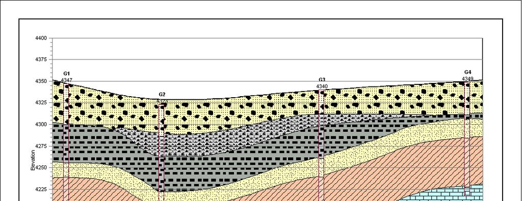
7 Boring Logs 7
8 8
9 METHODS OF INVESTIGATION 9
10 METHODS OF INVESTIGATION The methods to determine the sequence, thickness and lateral extent of the soil strata and, where appropriate the level of bedrock. The common methods include Test pits Shafts and audits Boring or drilling 10
11 Test Pits The excavation of test pits is a simple and reliable method. The depth is limited to 4-5m only. The in-situ conditions are examined visually It is easy to obtain disturbed and undisturbed samples Block samples can be cut by hand tools and tube samples can be taken from the bottom of the pit. 11
12 Walls of the test pit indicate four layers (1) Clayey silt (2) Sandy silt (3) Clean sand (4) Sandy gravel
13 Boring or Drilling Boring refers to advancing a hole in the ground. Boring is required for the following: To obtain representative soil and rock samples for laboratory tests. To identify the groundwater conditions. Performance of in-situ tests to assess appropriate soil characteristics. Some of the common types of boring are as follows Auger boring Wash boring Percussion boring Rotary drilling 13
14 Auger Boring Hand Auger Mechanical Auger Hand Auger It is the simplest method of boring used for small projects in soft cohesive soils. For hard soil and soil containing gravels boring with hand auger becomes difficult. Hand-augered augered holes can be made upto about 20m depth, although depth greater than about 8-10m is usually not practical. The length of the auger blade varies from m. 0.5m. The auger is rotated until it is full of soil, then it is withdrawn to remove the soil and the soil type present at various depths is noted. Repeated with drawl of auger for soil removal makes boring difficult below 8-10m depth. The soil samples collected in this manner are disturbed samples and can be used for classification test. Auger boring may not be possible in very soft clay or coarse sand because the hole tends to collapse when auger is removed 14 14
15 a. Helical (worm types) Augers b. Short flight Auger c. Iwan (posthole) Auger a b c 15
16 Mechanical Auger Mechanical Auger means power operated augers. The power required to rotate the auger depends on the type and size of auger and the type of soil. Downwards pressure can be applied hydraulically, mechanically or by dead weight a a b c a. Continuous Flight Auger b. Hallow-stem auger plugged during advancing bore c. Plug removed and sampler inserted d. Truck mounted auger boring machine d 16
17 The diameter of the flight auger usually is between 75 to 300mm, although diameters up to 1m and bucket augers up to2m are available. Borehole depths up to 50m are possible with continuous-flight augers. The most common method is to use continuous flight augers. Continuous flight augers can be solid stem or hollow stem with internal diameter of mm. Hollow stem augers are used when undisturbed samples are required. Plug is withdrawn and sampler is lowered down and driven in to the soil below the auger. If bed rock is reached drilling can also take place through the hollow stem. As the auger acts as a casing it can be used in sand below water table. The possibility of rising sand in to the stem by hydrostatic pressure can be avoided by filling the stem with water up to the water table 17 17
18 The soil rises to the surface along the helical blades, obviating the necessity of withdrawal. They are not suitable for soil bore that require casing, which demand removal of auger for driving the casing. The presence of cobbles and boulders create problems with small-sized sized augers. There is a possibility that different soil types may become mixed as they rise to the surface and it may be difficult to determine the depths of changes of strata. Experienced driller can however detect the change of strata by the change of speed and the sound of drilling. 18
19 Wash boring Water with high pressure pumped through hallow boring rods is released from narrow holes in a chisel attach to the lower end of the rods. The soil is loosened and broken by the water jet and the up- down moment of the chisel. The soil particles are carried in suspension to the surface between the rock and the borehole sites. The rods are raised and drop for chopping action of the chisel by means of winch. Wash boring can be used in most type of soil but the progress is slow in coarse gravel strata
20 The accurate identification of soil strata is difficult due to mixing of the material has they are carried to the surface. The method is unacceptable for obtaining soil samples. It is only used for advancing the borehole to enable tube sample to be taken or field test to be carried at the hole bottom. The advantage is that the soil immediately below the hole remains relatively un-disturbed 20
21 Wash boring rig 21
22 ROTARY DRILLING The rig consists of a derrick, power unit, winch, pump and a drill head to apply high-speed rotary drive and downward thrust to the drilling rods. Primarily intended for investigation in rock, but also used in soils. The drilling tool, (cutting bit or a coring bit) is attached to the lower end of hollow drilling rods The coring bit is fixed to the lower end of a core Water or drilling fluid is pumped down the hollow rods and passes under pressure through narrow holes in the bit or barrel The drilling fluid cools and lubricates the drilling tool and carries the loose debris to the surface between the rods and the side of the hole. 22
23 The fluid (bentonite slurry) also provides some support to the sides of the hole if no casing is used. There are two forms of rotary drilling, open-hole drilling and core drilling. Open- hole drilling, which is generally used in soils and weak rock, just for advancing the hole The drilling rods can then be removed to allow tube samples to be taken or in-situ tests to be carried out. In core drilling, which is used in rocks and hard clays, the diamond or tungsten carbide bit cuts an annular hole in the material and an intact core enters the barrel, to be removed as a sample. Typical core diameters are 41, 54 and 76mm, but can range up to 165 mm. 23
24 Advantages The advantage of rotary drilling in soils is that progress is much faster than with other investigation methods and disturbance of the soil below the borehole is slight. Limitations The method is not suitable if the soil contains a high percentage of gravel/cobbles, as they tend to rotate beneath the bit and are not broken up. The natural water content of the material is liable to be increased due to contact with the drilling fluid 24
25 Rotary Drilling rig 25
26 GEOPHYSICAL METHOD Although boring and test pits provide definite results but they are time consuming and expensive. Subsurface conditions are known only at the bore or test pit location. The subsurface conditions between the boring need to be interpolated or estimated. Geophysical methods are more quick and cheaper. They provide thorough coverage of the entire area. The results of Geophysical testing however are less definitive and require subjective interpretation. Therefore both methods are important. In case geophysical testing in major in scope, few borings and sampling will be required for accurate determination of soil properties. If boring is major in scope then few geophysical lines will be required to know the conditions in-between the borings. 26
27 Site Evaluation Direct Methods Boreholes/Probes Test Pits/Trenches Cores 27 27
28 Geophysical Techniques Indirect Methods Ground Penetrating Radar (GPR) Electromagnetic (EM) Magnetic Utility Locating Seismic Electrical Resistivity Gravity Very Low Frequency (VLF) 28


29 Geophysical Techniques Indirect Methods Advantages Non-Destructive Cost Effective Provides Preliminary or Supplemental Information 29 29
30 Soil Sampling Split Spoon/SPT sampler Thin-wall tube/shelby tube Augers 30
31 Soil Sampling Disturbed In situ structure not retained Water content, classification, compaction Undisturbed Less disturbed Shear strength, consolidation, permeability 31
32 Soil Sampling Disturbances Shearing and compression In situ stress release Drying Vibrations 32
33 How do we Sample Soil? Is it just digging holes? 33
34 Amount of sampling Depends upon; Time constraints Topography Cost factors Reasons for sampling There are no specific guidelines Soil Analysis Ch 8
35 Soil Sampling How many samples do we take? At least 20 single samples per m 2 must be taken with an earth boring tool (or spade) and combined to a mixed sample. To what depth do we sample? The usual sampling depth is up to 20 cm in arable land or 10cm in pasture. Undisturbed soil samples are obtained with a cutting cylinder with minimum capacity of 100cm
36 GROUND INVESTIGATION TESTING Selection of Testing for SPECIFIERS 36
37 Laboratory Testing Testing by a laboratory accredited to ISO is an essential part of soil and rock testing Competency of staff Control of test conditions Accuracy of test measurements Traceability of measurements to national standards Control of test material Repeatability of results 37
38 Laboratory Testing Soil and Water testing Rock Testing Chemical Testing (for effect on construction materials) Contamination (Analytical) Testing 38
39 Types of Laboratory Tests Classification tests Chemical Tests Compaction Tests Shear strength and triaxial tests Consolidation Tests Permeability Tests Specialist Tests Rock Tests Contamination Tests 39
40 Structuring the Test Schedule Design data required and for what purpose Identification of material characteristics Identification of contamination levels Type of sample needed Minimum mass of sample Multiple tests on samples
41 Classification Tests Moisture content Density Atterberg limits Particle size distribution
42 Rock Testing Classification (moisture, density, porosity, slake durability) Point load strength Uniaxial compressive strength and modulus Triaxial strength Permeability 42 42
43 Chemical Tests To provide design parameters for civil engineering materials in the ground ph, sulphate, chloride, carbonate Organic content and mass loss on ignition Special testing (eg SD1) 43 43
44 Compaction Tests Density/moisture content relationships California bearing ratio (CBR) Moisture condition value tests (MCV) Maximum/minimum density Combined relationship testing 44 44
45 Shear Strength and Triaxial Tests Shear Box Laboratory vane shear Quick undrained triaxial test (total stress) Consolidated undrained triaxial test (effective stress) Consolidated drained triaxial test (effective stress) Ring shear for residual strength 45 45
46 Consolidation Tests One dimensional consolidation Triaxial consolidation Hydraulic cells (Rowe) Swelling tests 46 46
47 Permeability Tests Constant head permeameter Falling head permeameter Triaxial permeability 47
48 Contamination Testing ph Organics Inorganics Metals Asbestos 48
Boreholes. Implementation. Boring. Boreholes may be excavated by one of these methods: 1. Auger Boring 2. Wash Boring 3.
 Implementation Boreholes 1. Auger Boring 2. Wash Boring 3. Rotary Drilling Boring Boreholes may be excavated by one of these methods: 4. Percussion Drilling The right choice of method depends on: Ground
ENCE 3610 Soil Mechanics. Site Exploration and Characterisation Field Exploration Methods
 ENCE 3610 Soil Mechanics Site Exploration and Characterisation Field Exploration Methods Geotechnical Involvement in Project Phases Planning Design Alternatives Preparation of Detailed Plans Final Design
Chapter 12 Subsurface Exploration
 Page 12 1 Chapter 12 Subsurface Exploration 1. The process of identifying the layers of deposits that underlie a proposed structure and their physical characteristics is generally referred to as (a) subsurface
Manual on Subsurface Investigations National Highway Institute Publication No. FHWA NHI Federal Highway Administration Washington, DC
 Manual on Subsurface Investigations National Highway Institute Publication No. FHWA NHI-01-031 Federal Highway Administration Washington, DC Geotechnical Site Characterization July 2001 by Paul W. Mayne,
Gotechnical Investigations and Sampling
 Gotechnical Investigations and Sampling Amit Prashant Indian Institute of Technology Gandhinagar Short Course on Geotechnical Investigations for Structural Engineering 12 14 October, 2017 1 Purpose of
KDOT Geotechnical Manual Edition. Table of Contents
 KDOT Geotechnical Manual 2007 Edition The KDOT Geotechnical Manual is available two volumes. Both volumes are very large electronic (pdf) files which may take several minutes to download. The table of
SITE INVESTIGATION 1
 SITE INVESTIGATION 1 Definition The process of determining the layers of natural soil deposits that will underlie a proposed structure and their physical properties is generally referred to as site investigation.
Module 1 : Site Exploration and Geotechnical Investigation
 Objectives In this section you will learn the following Displacement borings Wash boring Auger boring Rotary drilling Percussion drilling Continuous sampling Boring methods of exploration The boring methods
Week 3 : (3HL) Coverage : Typical geotechnical problems and usual application of SI methods
 Coverage : Typical geotechnical problems and usual application of SI methods") LEARNING OUTCOMES Week 3 : (3HL) Coverage : Typical geotechnical problems and usual application of SI methods Learning Outcomes : At the end of this lecture/week, the students will be able to : 1. Discuss
LEARNING OUTCOMES Week 3 : (3HL) Coverage : Typical geotechnical problems and usual application of SI methods Learning Outcomes : At the end of this lecture/week, the students will be able to : 1. Discuss
The process of determining the layers of natural soil deposits that will underlie a proposed structure and their physical properties is generally
 The process of determining the layers of natural soil deposits that will underlie a proposed structure and their physical properties is generally referred to as sub surface investigation 2 1 For proper
10. GEOTECHNICAL EXPLORATION PROGRAM
 Geotechnical site investigations should be conducted in multiple phases to obtain data for use during the planning and design of the tunnel system. Geotechnical investigations typically are performed in
Geotechnical Testing Methods I
 Geotechnical Testing Methods I Ajanta Sachan Assistant Professor Civil Engineering IIT Gandhinagar Hiding World of Geotechnical Engg!! Foundations Shoring Tunneling Soil Exploration Geotechnical Engg Structures
Chapter 3 SUBSOIL EXPLORATION. Omitted parts: Sections & 3.24, 3.25 Examples 3.3, 3.4,3.5
 Chapter 3 SUBSOIL EXPLORATION Omitted parts: Sections 3.2-3.10 & 3.24, 3.25 Examples 3.3, 3.4,3.5 GENERAL OBSERVATION Soil does not posses a unique or linear stress-strain relationship. Soil behavior depends
 UNIT I SITE INVESTIGATION AND SELECTION OF FOUNDATION Types of boring 1.Displacement borings It is combined method of sampling & boring operation. Closed bottom sampler, slit cup, or piston type is forced
SI Planning & Laboratory Testing for Hill-Site Development
 SI Planning & Laboratory Testing for Hill-Site Development 21 April 2009 IEM Penang Ir. Tan Yean Chin G&P Geotechnics Sdn Bhd Cameron Highlands, 1961 Genting Highland Tower 1993 Bukit Antarabangsa, 1999
GEOTECHNICAL ENGINEERING II. Subject Code : 06CV64 Internal Assessment Marks : 25 PART A UNIT 1
 GEOTECHNICAL ENGINEERING II Subject Code : 06CV64 Internal Assessment Marks : 25 PART A UNIT 1 1. SUBSURFACE EXPLORATION 1.1 Importance, Exploration Program 1.2 Methods of exploration, Boring, Sounding
SHEAR STRENGTH OF SOIL
 Soil Failure Criteria SHEAR STRENGTH OF SOIL Knowledge about the shear strength of soil important for the analysis of: Bearing capacity of foundations, Slope stability, Lateral pressure on retaining structures,
Highway Subsurface Exploration
 Highway Subsurface Exploration D. G. S hurig, Research A ssistant E. J. Yoder, Research E ngineer Joint Highway Research Project Purdue University Introduction This paper pertains to the operation and
Rotary Drilling Rotary Drilling Bits
 GE 343 SUBSURFACE EXPLORATION CH 8 Rock Drilling, Testing, and Sampling Text Ch. 7. Dr. Norbert H. Maerz Missouri University of Science and Technology (573) 341-6714 norbert@mst.edu Instructional Objectives
Underground Risk Management Course Marina Del Rey, California November, Geotechnical Data Reports. Greg Raines, PE
 Underground Risk Management Course Marina Del Rey, California November, 2018 Geotechnical Data Reports Greg Raines, PE Gregory.Raines@Stantec.com Introduction What is a Geotechnical Data Report? The GDR
APPENDIX F CORRELATION EQUATIONS. F 1 In-Situ Tests
 APPENDIX F 1 APPENDIX F CORRELATION EQUATIONS F 1 In-Situ Tests 1. SPT (1) Sand (Hatanaka and Uchida, 1996), = effective vertical stress = effective friction angle = atmosphere pressure (Shmertmann, 1975)
Instructional Objectives
 GE 343 SUBSURFACE EXPLORATION CH 8 Rock Drilling, Testing, and Sampling Text Ch. 7. Dr. Norbert H. Maerz Missouri University of Science and Technology (573) 341-6714 norbert@mst.edu Instructional Objectives
Conventional Field Testing & Issues (SPT, CPT, DCPT, Geophysical methods)
") Conventional Field Testing & Issues (SPT, CPT, DCPT, Geophysical methods) Ajanta Sachan Assistant Professor Civil Engineering IIT Gandhinagar Conventional Field Testing 1 Field Test: In-situ shear strength
Conventional Field Testing & Issues (SPT, CPT, DCPT, Geophysical methods) Ajanta Sachan Assistant Professor Civil Engineering IIT Gandhinagar Conventional Field Testing 1 Field Test: In-situ shear strength
The attitude he maintains in his relation to the engineer is very well stated in his own words:
 Su bsurface Soil Exploration, 53: 139 Foundation Engineering Geotechnical companies that have a history of experience in a given region usually have extensive boring logs and maps telling where the borings
NHBRA SOIL LABORATORY SECTION INTERIM REVISED TEST RATES FOR THE MATERIALS LABORATORY
 NHBRA SOIL LABORATORY SECTION INTERIM REVISED TEST RATES FOR THE MATERIALS LABORATORY DATE OF REVISION: ) 10th October 2010 S/N TEST DESCRIPTION UNIT RATE REMARKS 1 Sieve Analysis (wet and dry methods
How to Interpret Mining Company Drill Reports & Announcements
 How to Interpret Mining Company Drill Reports & Announcements A Simple Guide amscot Stockbroking Pty Ltd A division of State One Stockbroking Ltd (AFSL 247 100) Disclaimer: All information in this document
Chapter 5 Shear Strength of Soil
 Page 5 Chapter 5 Shear Strength of Soil. The internal resistance per unit area that the soil mass can offer to resist failure and sliding along any plane inside it is called (a) strength (b) shear strength
GUIDELINE FOR HAND HELD SHEAR VANE TEST
 GUIDELINE FOR HAND HELD SHEAR VANE TEST NZ GEOTECHNICAL SOCIETY INC August 2001 CONTENTS Page 1.0 Introduction 2 2.0 Background 2 3.0 Recommended Practice 3 4.0 Undrained Shear Strength 3 5.0 Particular
Soils. Technical English - I 10 th week
 Technical English - I 10 th week Soils Soil Mechanics is defined as the branch of engineering science which enables an engineer to know theoretically or experimentally the behavior of soil under the action
Advanced Foundation Engineering
 2013 Advanced Foundation Engineering Prof.T.G. Sitharam Indian Institute of Science, Bangalore CHAPTER 1: Soil Exploration 1.1 Introduction 1.2 Boring of Holes 1.2.1 Auger Method 1.2.1.1 Hand Operated
Geotechnical Geotechnical Assessment
 Site Investigation Site Investigation Pile Probing Pile Probing Geotechnical Logging Geotechnical and Sampling Logging and Sampling Streetworks and Utilities Streetworks Avoidance and Utilities Avoidance
SASKATCHEWAN STRATIGRAPHY GLACIAL EXAMPLE BOULDERS IN GLACIAL DEPOSITS
 SASKATCHEWAN STRATIGRAPHY GLACIAL EXAMPLE BOULDERS IN GLACIAL DEPOSITS 51 SASKATCHEWAN STRATIGRAPHY GLACIAL SURFICIAL STRATIFIED DEPOSITS 52 SASKATCHEWAN STRATIGRAPHY GLACIAL EXAMPLE OF SEDIMENT DEPOSITION
APPENDIX A. Borehole Logs Explanation of Terms and Symbols
 APPENDIX A Borehole Logs Explanation of Terms and Symbols Page 153 of 168 EXPLANATION OF TERMS AND SYMBOLS The terms and symbols used on the borehole logs to summarize the results of field investigation
Schedule of Accreditation issued by United Kingdom Accreditation Service 2 Pine Trees, Chertsey Lane, Staines-upon-Thames, TW18 3HR, UK
 2 Pine Trees, Chertsey Lane, Staines-upon-Thames, TW18 3HR, UK Parkside Lane Dewsbury Road Leeds LS11 5SX Contact: Mr K Walker Tel: +44 (0)113 385 9157 Fax: +44 (0)113 276 0472 E-Mail: Kevin.Walker@soil-engineering.co.uk
 QUESTION BANK DEPARTMENT: CIVIL SUBJECT CODE / Name: CE 2251 / SOIL MECHANICS SEMESTER: IV UNIT 1- INTRODUCTION PART - A (2 marks) 1. Distinguish between Residual and Transported soil. (AUC May/June 2012)
Appendix J. Geological Investigation
 Appendix J Geological Investigation Appendix J Geological Environment Table of Contents Page 1 INTRODUCTION...J-1 1.1 Purpose of the Investigation...J-1 1.2 Scope of the Investigation...J-1 2 METHODO OF
General. DATE December 10, 2013 PROJECT No TO Mary Jarvis Urbandale/Riverside South Development Corporation
 DATE December 10, 201 PROJECT No. 10-1121-0260- TO Mary Jarvis Urbandale/Riverside South Development Corporation CC Justin Robitaille, Urbandale Jonathan Párraga, J.L. Richards & Associates Limited FROM
GEOTECHNICAL INVESTIGATION REPORT INFRASTRUCTURE PVT LTD
 GEOTECHNICAL INVESTIGATION REPORT Client : TAEIN CONSTRUCTION & INFRASTRUCTURE PVT LTD Office address : Flat No.104, A -Wing,1st floor,gloria Park, Paranjape Scheme, Bavdhan Khurd, Chandni Chowk, Pune
Introduction to Soil Mechanics Geotechnical Engineering
 Introduction to Soil Mechanics Geotechnical Engineering Dr. Attaullah Shah ground SIVA 1 Soil Mechanics= Soil+Mechanics Branch of Science dealing with the structure, Engineering properties and reactions
An Introduction to Field Explorations for Foundations
 An Introduction to Field Explorations for Foundations J. Paul Guyer, P.E., R.A. Paul Guyer is a registered mechanical engineer, civil engineer, fire protection engineer and architect with over 35 years
B-1 BORE LOCATION PLAN. EXHIBIT Drawn By: 115G BROOKS VETERINARY CLINIC CITY BASE LANDING AND GOLIAD ROAD SAN ANTONIO, TEXAS.
 N B-1 SYMBOLS: Exploratory Boring Location Project Mngr: BORE LOCATION PLAN Project No. GK EXHIBIT Drawn By: 115G1063.02 GK Scale: Checked By: 1045 Central Parkway North, Suite 103 San Antonio, Texas 78232
SHEAR STRENGTH OF SOIL
 SHEAR STRENGTH OF SOIL Necessity of studying Shear Strength of soils : Soil failure usually occurs in the form of shearing along internal surface within the soil. Shear Strength: Thus, structural strength
IN SITU SPECIFIC GRAVITY VS GRAIN SIZE: A BETTER METHOD TO ESTIMATE NEW WORK DREDGING PRODUCTION
 IN SITU SPECIFIC GRAVITY VS GRAIN SIZE: A BETTER METHOD TO ESTIMATE NEW WORK DREDGING PRODUCTION Nancy Case O Bourke, PE 1, Gregory L. Hartman, PE 2 and Paul Fuglevand, PE 3 ABSTRACT In-situ specific gravity
IAEA SAFETY STANDARDS Geotechnical Aspects of Site Evaluation and Foundations in NPPs, NS-G-3.6
 IAEA SAFETY STANDARDS Geotechnical Aspects of Site Evaluation and Foundations in NPPs, NS-G-3.6 Regional Workshop on Volcanic, Seismic, and Tsunami Hazard Assessment Related to NPP Siting Activities and
PRINCIPLES OF GEOTECHNICAL ENGINEERING
 PRINCIPLES OF GEOTECHNICAL ENGINEERING Fourth Edition BRAJA M. DAS California State University, Sacramento I(T)P Boston Albany Bonn Cincinnati London Madrid Melbourne Mexico City New York Paris San Francisco
Site Investigations and Geotechnical Risk For Underground Construction Greg Raines, PE
 August 14, 2017 Site Investigations and Geotechnical Risk For Underground Construction Greg Raines, PE Gregory.Raines@Stantec.com Develop Preliminary Geologic / Geotech Conceptual Model for the Project
CONTENTS. 1. GeneralsG Field Investigation WorkG Laboratory Testing Work Surface Soil Description-- 7.
 CONTENTS Page 1. GeneralsG 4 2. Field Investigation WorkG 4 3. Laboratory Testing Work--- 5 4. Surface Soil Description-- 7 Appendix A Borehole Location Plan 11 Soil Profile-- 15 Bore Logs--=---- 18 Appendix
Soil Mechanics Brief Review. Presented by: Gary L. Seider, P.E.
 Soil Mechanics Brief Review Presented by: Gary L. Seider, P.E. 1 BASIC ROCK TYPES Igneous Rock (e.g. granite, basalt) Rock formed in place by cooling from magma Generally very stiff/strong and often abrasive
CE 240 Soil Mechanics & Foundations Lecture 5.2. Permeability III (Das, Ch. 6) Summary Soil Index Properties (Das, Ch. 2-6)
 Summary Soil Index Properties (Das, Ch. 2-6)") CE 40 Soil Mechanics & Foundations Lecture 5. Permeability III (Das, Ch. 6) Summary Soil Index Properties (Das, Ch. -6) Outline of this Lecture 1. Getting the in situ hydraulic conductivity 1.1 pumping
CE 40 Soil Mechanics & Foundations Lecture 5. Permeability III (Das, Ch. 6) Summary Soil Index Properties (Das, Ch. -6) Outline of this Lecture 1. Getting the in situ hydraulic conductivity 1.1 pumping
CHAPTER 3.0 DRILLING AND SAMPLING OF SOIL AND ROCK
 HAPTER 3.0 DRILLING AND SAMPLING OF SOIL AND ROK This chapter describes the equipment and procedures commonly used for the drilling and sampling of soil and rock. The methods addressed in this chapter
Table of Contents Chapter 1 Introduction to Geotechnical Engineering 1.1 Geotechnical Engineering 1.2 The Unique Nature of Soil and Rock Materials
 Table of Contents Chapter 1 Introduction to Geotechnical Engineering 1.1 Geotechnical Engineering 1.2 The Unique Nature of Soil and Rock Materials 1.3 Scope of This Book 1.4 Historical Development of Geotechnical
GEOTECHNICAL INVESTIGATION OF RAILWAYS
 GEOTECHNICAL INVESTIGATION OF RAILWAYS Prof. Hannes Gräbe University of Pretoria Transnet Chair in Railway Engineering May 2011 Contents Cost considerations Objectives Phased approach to site investigation
Introduction to Soil Mechanics
 Introduction to Soil Mechanics Sela Sode and Colin Jones WILEY Blackwell Contents Preface Dedication and Acknowledgments List of Symbols Soil Structure 1.1 Volume relationships 1.1.1 Voids ratio (e) 1.1.2
Core Barrels. Core Barrels
 Core Barrels To collect the core of the rock drilled, a device known as the core barrel is used. Core barrel retains rock core samples from drilling operations Its length varies from 0.5 to 3 m. There
East Land Quality Forum Drilling Techniques; Old and New
 East Land Quality Forum Drilling Techniques; Old and New 1 Introduction Different Drilling Methods Rota-sonic drilling What is it and how does it work? Different types of Rota-Sonic/Sonic Drilling Rigs
LECTURE 10. Module 3 : Field Tests in Rock 3.6 GEOPHYSICAL INVESTIGATION
 LECTURE 10 3.6 GEOPHYSICAL INVESTIGATION In geophysical methods of site investigation, the application of the principles of physics are used to the study of the ground. The soil/rock have different characteristics
GEOTECHNICAL POLICIES AND PROCEDURES MANUAL CHAPTER 5 GEOTECHNICAL INVESTIGATION PLANNING GUIDELINES
 GEOTECHNICAL POLICIES AND PROCEDURES MANUAL CHAPTER 5 GEOTECHNICAL INVESTIGATION PLANNING GUIDELINES GEOTECHNICAL INVESTIGATION PLANNING GUIDELINES 5-i TABLE OF CONTENTS 1. PURPOSE... 1 2. INTRODUCTION...
Enhanced In-Situ Testing for Geotechnical Site Characterization. Graduate Course CEE 6423
 Enhanced In-Situ Testing for Geotechnical Site Characterization SPT, VST, DMT, PMT, CHT, DHT, CPT Graduate Course CEE 6423 Paul W. Mayne, PhD, P.E. Professor, Geosystems Program Civil & Environmental Engineering
THE INSTITUTE OF COST ACCOUNTANTS OF INDIA (ICAI)
") THE INSTITUTE OF COST ACCOUNTANTS OF INDIA (ICAI) GEOTECHNICAL INVESTIGATION REPORT FOR PROPOSED PROJECT INSTITUTIONAL BUILDING FOR ICAI AT CBD BELAPUR, NAVI MUMBAI OCTOBER 2012 1281-2012-073 BY THANE
THE INSTITUTE OF COST ACCOUNTANTS OF INDIA (ICAI) GEOTECHNICAL INVESTIGATION REPORT FOR PROPOSED PROJECT INSTITUTIONAL BUILDING FOR ICAI AT CBD BELAPUR, NAVI MUMBAI OCTOBER 2012 1281-2012-073 BY THANE
APPENDIX C. Borehole Data
 APPENDIX C Borehole Data MAJOR DIVISIONS SOIL CLASSIFICATION CHART SYMBOLS GRAPH LETTER TYPICAL DESCRIPTIONS ADDITIONAL MATERIAL
CHAPTER 3 PLANNING A SUBSURFACE INVESTIGATION AND LABORATORY TESTING PROGRAM
 CHAPTER 3 PLANNING A SUBSURFACE INVESTIGATION AND LABORATORY TESTING PROGRAM 3.1 INTRODUCTION To evaluate soil and rock properties required for geotechnical design related to transportation projects, subsurface
Chapter (12) Instructor : Dr. Jehad Hamad
 Instructor : Dr. Jehad Hamad") Chapter (12) Instructor : Dr. Jehad Hamad 2017-2016 Chapter Outlines Shear strength in soils Direct shear test Unconfined Compression Test Tri-axial Test Shear Strength The strength of a material is the
Chapter (12) Instructor : Dr. Jehad Hamad 2017-2016 Chapter Outlines Shear strength in soils Direct shear test Unconfined Compression Test Tri-axial Test Shear Strength The strength of a material is the
Early Exploration Plan Activity Information
 Early Exploration Plan Activity Information Activities That Require an Early Exploration Plan: Line cutting that is a width of 1.5 metres or less; Geophysical surveys on the ground requiring the use of
Cyclic Behavior of Sand and Cyclic Triaxial Tests. Hsin-yu Shan Dept. of Civil Engineering National Chiao Tung University
 Cyclic Behavior of Sand and Cyclic Triaxial Tests Hsin-yu Shan Dept. of Civil Engineering National Chiao Tung University Causes of Pore Pressure Buildup due to Cyclic Stress Application Stress are due
Introduction to Soil Mechanics Geotechnical Engineering-II
 Introduction to Soil Mechanics Geotechnical Engineering-II ground SIVA Dr. Attaullah Shah 1 Soil Formation Soil derives from Latin word Solum having same meanings as our modern world. From Geologist point
GEOTECHNICAL INVESTIGATION REPORT
 GEOTECHNICAL INVESTIGATION REPORT SOIL INVESTIGATION REPORT FOR STATIC TEST FACILITY FOR PROPELLANTS AT BDL, IBRAHIMPATNAM. Graphics Designers, M/s Architecture & Engineering 859, Banjara Avenue, Consultancy
(Refer Slide Time: 02:18)
") Geology and Soil Mechanics Prof. P. Ghosh Department of Civil Engineering Indian Institute of Technology Kanpur Lecture 40 Shear Strength of Soil - C Keywords: Shear strength of soil, direct shear test,
Geology and Soil Mechanics Prof. P. Ghosh Department of Civil Engineering Indian Institute of Technology Kanpur Lecture 40 Shear Strength of Soil - C Keywords: Shear strength of soil, direct shear test,
3.0 SUMMARY OF FINDINGS
 AECOM 500 W Jefferson St. Suite 1600 Louisville, KY 40202 www.aecom.com 502-569-2301 tel 502-569-2304 fax October 17, 2018 Big Rivers Electric Corporation Sebree Generating Station 9000 Highway 2096 Robards,
Interpretation of Pile Integrity Test (PIT) Results
 Results") Annual Transactions of IESL, pp. 78-84, 26 The Institution of Engineers, Sri Lanka Interpretation of Pile Integrity Test (PIT) Results H. S. Thilakasiri Abstract: A defect present in a pile will severely
Annual Transactions of IESL, pp. 78-84, 26 The Institution of Engineers, Sri Lanka Interpretation of Pile Integrity Test (PIT) Results H. S. Thilakasiri Abstract: A defect present in a pile will severely
Chapter 1 Introduction
 Chapter 1 Introduction 1.1 Statement of the Problem Engineering properties of geomaterials are very important for civil engineers because almost everything we build - tunnels, bridges, dams and others
Foundation Engineering Prof. Mahendra Singh Department of Civil Engineering Indian Institute of Technology, Roorkee
 Foundation Engineering Prof. Mahendra Singh Department of Civil Engineering Indian Institute of Technology, Roorkee Module - 03 Lecture - 05 Field Tests Hello viewers, welcome back to the course on Foundation
1.8 Unconfined Compression Test
 1-49 1.8 Unconfined Compression Test - It gives a quick and simple measurement of the undrained strength of cohesive, undisturbed soil specimens. 1) Testing method i) Trimming a sample. Length-diameter
EVALUATION OF STRENGTH OF SOILS AGAINST LIQUEFACTION USING PIEZO DRIVE CONE
 4 th International Conference on Earthquake Geotechnical Engineering June 25-28, 2007 Paper No. 1146 EVALUATION OF STRENGTH OF SOILS AGAINST LIQUEFACTION USING PIEZO DRIVE CONE Shun-ichi Sawada 1 ABSTRACT
Exploration Drilling Techniques
 Exploration Techniques Why do we need natural resources? average increase in demand: 5 % per year How do we find new resources? How do we find new resources? Fun! Geological methods: In my view the greatest
VALLIAMMAI ENGINEERING COLLEGE
 VALLIAMMAI ENGINEERING COLLEGE DEPARTMENT OF CIVIL ENGINEERING SUBJECT CODE : CE6405 YEAR : II SUBJECT NAME : SOIL MECHANICS SEM : IV QUESTION BANK (As per Anna University 2013 regulation) UNIT 1- SOIL
Principal Symbols. f. Skin friction G Shear modulus. Cu Coefficient of uniformity Cc Coefficient of curvature
 Principal Symbols A, a Area A Air content A, A Pore pre.ssure coefficients a' Modified shear strength parameter (effective stress) a Dial gauge reading in oedometer test B Width of footing B, B Pore pressure
iii CONTENTS vii ACKNOWLEDGMENTS EXECUTIVE SUMMARY INTRODUCTION Study Area Data Sources Preparation of Geologic Maps
 CONTENTS ACKNOWLEDGMENTS EXECUTIVE SUMMARY INTRODUCTION Study Area Data Sources Preparation of Geologic Maps GEOLOGY Bedrock Geology Succession and Distribution Structural Features Description of Bedrock
Triaxial Shear Test. o The most reliable method now available for determination of shear strength parameters.
 TOPICS Introduction Components of Shear Strength of Soils Normal and Shear Stresses on a Plane Mohr-Coulomb Failure Criterion Laboratory Shear Strength Testing Direct Shear Test Triaxial Compression Test
Measurement of effective stress shear strength of rock
 Measurement of effective stress shear strength of rock R. A. Failmezger, P.E., F. ASCE In-Situ Soil Testing, L.C., Lancaster, Virginia USA D. J. White, Ph. D., P.E. Iowa State University, Ames, Iowa USA
Pierce County Department of Planning and Land Services Development Engineering Section
 Page 1 of 7 Pierce County Department of Planning and Land Services Development Engineering Section PROJECT NAME: DATE: APPLICATION NO.: PCDE NO.: LANDSLIDE HAZARD AREA (LHA) GEOLOGICAL ASSESSMENT REPORT
Cone Penetration Testing in Geotechnical Practice
 Cone Penetration Testing in Geotechnical Practice Table Of Contents: LIST OF CONTENTS v (4) PREFACE ix (2) ACKNOWLEDGEMENTS xi (1) SYMBOL LIST xii (4) CONVERSION FACTORS xvi (6) GLOSSARY xxii 1. INTRODUCTION
Role of the Geotechnical Consultant in Design Build Projects a General Contractors Geotechnical Engineer s Perspective
 Role of the Geotechnical Consultant in Design Build Projects a General Contractors Geotechnical Engineer s Perspective Steven R. Saye Kiewit Engineering Group, Inc. Design Build Geotechnical Goal All parties
Depth (ft) USCS Soil Description TOPSOIL & FOREST DUFF
 USCS Soil Description TOPSOIL & FOREST DUFF") Test Pit No. TP-6 Location: Latitude 47.543003, Longitude -121.980441 Approximate Ground Surface Elevation: 1,132 feet Depth (ft) USCS Soil Description 0 1.5 1.5 5.0 SM 5.0 8.0 SM Loose to medium dense,
Test Pit No. TP-6 Location: Latitude 47.543003, Longitude -121.980441 Approximate Ground Surface Elevation: 1,132 feet Depth (ft) USCS Soil Description 0 1.5 1.5 5.0 SM 5.0 8.0 SM Loose to medium dense,
Appendix E. Phase 2A Geotechnical Data
 Appendix E Phase 2A Geotechnical Data Appendix E1 Geotechnical Testing of Sediment ApPENDIX El. GEOTECHNICAL TESTING OF SEDIMENT (Modified from Exponent, 20Q1c) E.I Introduction This appendix presents
June 9, R. D. Cook, P.Eng. Soils Engineer Special Services Western Region PUBLIC WORKS CANADA WESTERN REGION REPORT ON
 PUBLIC WORKS CANADA WESTERN REGION REPORT ON GEOTECHNICAL INVESTIGATION PROPOSED MARTIN RIVER BRIDGE MILE 306.7 MACKENZIE HIGHWAY Submitted by : R. D. Cook, P.Eng. Soils Engineer Special Services Western
Geotechnical Investigation Juneau Seawalk - Taku Fisheries to Miner s Wharf Juneau, Alaska DM&A Job No
 Duane Miller & Associates 5821 Arctic Boulevard, Suite A Anchorage, AK 99518-1654 (907) 644-3200 Fax 644-0507 Arctic & Geotechnical Engineering May 4, 2006 Tetra Tech/KCM, Inc. 1971 First Avenue Seattle,
REQUEST FOR QUOTATION FOR ONSHORE GEOTECHNICAL INVESTIGATION
 MLT-II JETTY AT KAMARAJAR PORT REQUEST FOR QUOTATION FOR ONSHORE GEOTECHNICAL INVESTIGATION Consultant DEPARTMENT OF OCEAN ENGINEERING INDIAN INSTITUTE OF TECHNOLOGY MADRAS CHENNAI 600 036 Client Hindustan
SOIL MECHANICS: palgrave. Principles and Practice. Graham Barnes. macmiiian THIRD EDITION
 SOIL MECHANICS: Principles and Practice THIRD EDITION Graham Barnes palgrave macmiiian 'running Contents Preface xii Fine soil 19 List of symbols xiv Mass structure 21 Note on units xix Degree of weathering
Horizontal Directional Drilling: An Approach to Design and Construction. Presenter: John Briand, PE Co-Author: Danielle Neamtu, PE
 Horizontal Directional Drilling: An Approach to Design and Construction Presenter: John Briand, PE Co-Author: Danielle Neamtu, PE Presentation Outline General HDD overview Conceptual-level evaluation Detailed
ATTACHMENT A PRELIMINARY GEOTECHNICAL SUMMARY
 ATTACHMENT A PRELIMINARY GEOTECHNICAL SUMMARY Kevin M. Martin, P.E. KMM Geotechnical Consultants, LLC 7 Marshall Road Hampstead, NH 0384 603-489-6 (p)/ 603-489-8 (f)/78-78-4084(m) kevinmartinpe@aol.com
Geotechnical Indications Of Eastern Bypass Area In Port Harcourt, Niger Delta
 Geotechnical Indications Of Eastern Bypass Area In Port Harcourt, Niger Delta Warmate Tamunonengiyeofori Geostrat International Services Limited, Rivers State, Nigeria www.geostratinternational.com info@geostratinternational.com,
 SOIL CLASSIFICATION CHART COARSE-GRAINED SOILS MORE THAN 50% RETAINED ON NO.200 SIEVE FINE-GRAINED SOILS 50% OR MORE PASSES THE NO.200 SIEVE PRIMARY DIVISIONS GRAVELS MORE THAN 50% OF COARSE FRACTION RETAINED
APPENDIX C HYDROGEOLOGIC INVESTIGATION
 Figure B-5.7 Figure B-5.8 Preliminary Geotechnical and Environmental Report Appendix C Hydrogeologic Investigation APPENDIX C HYDROGEOLOGIC INVESTIGATION December 21, 2011 WESTSIDE SUBWAY EXTENSION PROJECT
APPENDIX E SOILS TEST REPORTS
 Otsego County, NY Site Work Specifications APPENDIX E SOILS TEST REPORTS Blue Wing Services, Inc. July 1, 2010 Blue Wing Services May 20, 2010 Page 2 the site, was not made available to Empire at this
Site Characterization & Hydrogeophysics
 Site Characterization & Hydrogeophysics (Source: Matthew Becker, California State University) Site Characterization Definition: quantitative description of the hydraulic, geologic, and chemical properties
REPORT OF SUBSURFACE EXPLORATION
 REPORT OF SUBSURFACE EXPLORATION GRAND RIVER DAM AUTHORITY HULBERT 69 KV SWITCHING STATION S. 440 Road Hulbert, Cherokee County, Oklahoma ENERCON PROJECT NO. GRDA006 MARCH 7, 2012 PREPARED FOR: C/O ENERCON
Safe bearing capacity evaluation of the bridge site along Syafrubesi-Rasuwagadhi road, Central Nepal
 Bulletin of the Department of Geology Bulletin of the Department of Geology, Tribhuvan University, Kathmandu, Nepal, Vol. 12, 2009, pp. 95 100 Safe bearing capacity evaluation of the bridge site along
Geotechnical Engineering Report
 Geotechnical Engineering Report Turner Turnpike Widening Polecat Creek Bridge (Bridge A) June 1, 2016 Terracon Project No. 04155197 Prepared for: Garver, LLC Prepared by: Terracon Consultants, Inc. TABLE
Instructional Objectives
 GE 343 SUBSURFACE EXPLORATION CH 6 Drilling in Overburden Text Ch. 7. Dr. Norbert H. Maerz Missouri University of Science and Technology (573) 341-6714 norbert@mst.edu Instructional Objectives 1. List
Liquefaction Resistance and Internal Erosion Potential of Non-Plastic Silty Sand
 Liquefaction Resistance and Internal Erosion Potential of Non-Plastic Silty Sand Jing-Wen CHEN 1, Wei F. LEE 2, Chun-Chi CHEN 3 1 Professor, Department of Civil Engineering, National Chen-Kung University