Instructional Objectives
|
|
|
- Eugenia Paul
- 5 years ago
- Views:
Transcription
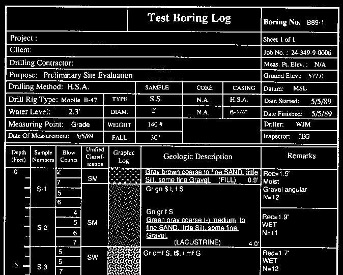
1 GE 343 SUBSURFACE EXPLORATION CH 6 Drilling in Overburden Text Ch. 7. Dr. Norbert H. Maerz Missouri University of Science and Technology (573) norbert@mst.edu Instructional Objectives 1. List the rules of thumb for boring spacing and depths. 2. Explain the requirements for locating underground services before you dig. 3. Select and justify a drilling method for a given design use and geological scenario. 4. Select and justify a sampling method and strategy for a given design use and geological scenario. 5. Select and justify an insitu testing method and strategy for a given design use and geological scenario. 1
2 Exploration Program Evaluate the variety of methods and procedures available Depends on the type of construction and the geological conditions encountered Exploration Plan 1. Key locations to clarify the geological interpretation as a whole. 2. Key location that could lead to relocation or redesign. 3. Bridges or other structures. 4. Deep cuts and high embankments. 5. Areas of engineering difficulty or complicated ground surface. 6. Off-line investigations for geological hazards or borrow surveys. 2
3 Exploration Plan 7. Points of Interpolation (function of complexity of the geology). 8. Least expensive methods of investigation should be used first. These may provide sufficient information by themselves, or will indicate where more detailed and expensive investigations may be required. 9. In areas of intense, complex, or expensive construction activity, it may be necessary to conduct very sophisticated and expensive which include horizontal boring, inspection shafts or pilot tunnels. Types of Borings 1. Pilot borings 2. Control borings 3. Verification borings 3
4 Exploration Spacing 1. Narrow right of ways 150 m 2. Uniform conditions for subgrade m, up to 300 m in the Midwest 3. With increasing complexity m 4. Highly erratic critical foundations 8-15 m 5. High embankments and deep cuts 60 m, in compressible materials 30 m 6. Specific structure borings, 30 m or at each end of the structure Exploration Spacing 7. Critical Areas (irregular bedrock, bogs, caverns 15 m grid 8. Tunnels: soft ground adverse conditions m, favorable conditions m 9. Tunnels: mixed-face adverse conditions 8-15 m, favorable conditions m 10.Tunnels: hard ground adverse conditions m, favorable conditions m 4
5 Exploration Depths 1. Subgrade borings 2-3 meters below profile elevation 2. High embankments, 2-4 times the height of the embankment 3. Excavations > 5 m, 2 times depth 4. Specific structure borings- to depth of where net increase in soil stress due to structural load is less than 10 of effective stress. Minimum 10 m below footing (3 m into rock) Exploration Depths 5. Critical Areas deep enough to evaluate their extent 6. Tunnel borings: 1 to 1.5 time tunnel diameter below grade. If alignment is subject to modifications, then 2 to 3 times 5
6 Sampling Requirements Every change in soil strata At interval not to exceed 1.5 m Rock core continuously Right of Way, Permits, Utilities Permission from property owners, preferably written Formalized permits for certain access Underground utilities Overhead utilities 6


7 1-800-Dig-Rite /excavmanual.pdf 7
")
8 Color codes Soil Drilling Methods Displacement boring Wash boring Percussive drilling (rock) Rotary drilling (rock) Auger boring Sonic Drilling 8

9 Displacement Boring Method where a piston or plug-type sampler is forced into the soil to the desired depth, displacing all the material on its path. Upon reaching the desired depth, the sampler is retracted and "grabs' a sample on its way back to the surface. PROS: Does not require heavy equipment (by hand or lightweight equipment); Clean method for shallow well installation; CONS: Method limited to shallow depths; Method limited to soft soils and boulder, cobble-free zones; Not efficient if necessary to install several wells; Practical limitation up to ~ 2" diameter sampler. Similar to the above method is "Direct Push Technology" or DPT. A common trade name is GeoProbe. DPT does not require heavy equipment, most units are pickup mounted or ATV mounted for easy accessibility. Wash Borings 9


10 Continuous Flight Augers Construction Augers Solid stem Hollow stem Truck mounted Track mounted Construction Auger 10

11 Solid Stem Continuous Flight Augers FHWA NHI

12 Solid-stem auger Method consists of drilling a continuous helix into the ground. The torque is provided by a top drive auger drilling machine, which permits both downward push and retraction. Individual flights are normally 5 feet long. Different drill bits can be attached to the bottom of the auger to meet the formation requirement, which cut a hole ~10 % greater in diameter than the diameter of the auger. PROS: Rapid and low-cost drilling in clayey formations; Clean method, does not require circulation fluids; No casing necessary where the formation is stable; Allows collection of representative sample in semi-consolidated formations; CONS: Practical limitation to 24" diameter; Inefficient in loose, sandy material (depends on the depth); Inefficient below the water table (depends on the depth). Hollow Stem Continuous Flight Augers FHWA NHI
13 13


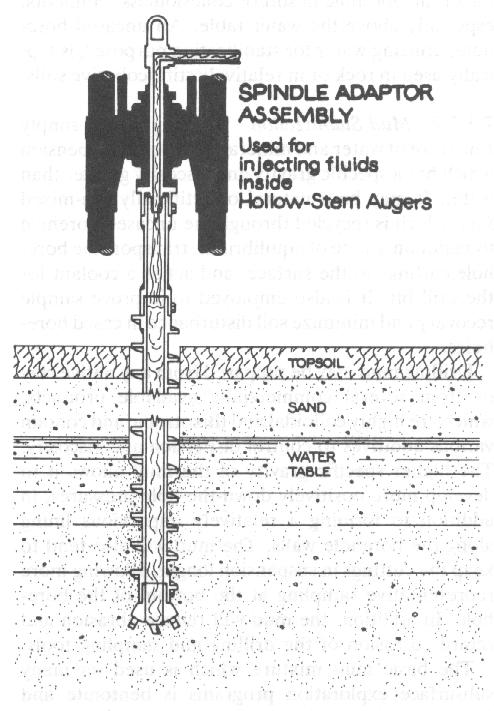
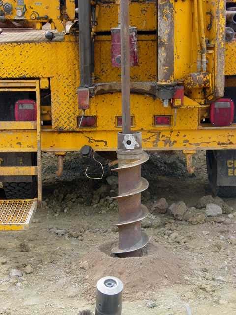
14 Hollow-stem auger This is a form of continuous-flight auger where the helices are wound around and welded to a tubular center stem or axle. Drilling proceeds essentially as in solid-stem drilling. When the sections are connected however, the hollow-stem auger will present a smooth, uniform bore throughout its length thus providing an open, cased hole in which samplers can be used or well installation can be performed. Other drilling methods can also proceed within the hollow stem, which can be used as temporary casing to prevent caving. PROS: Allows collection of uncontaminated sample in unconsolidated formation; Can be used as temporary casing to prevent caving; Relatively rapid, especially in clayey formations; CONS: Ineffective through boulders; Limited drilling in loose, granular soils, particularly below the water table where sample recovery can be compromised; Difficult to retrieve a sample in loose, granular soil because cuttings don't always want to come to the surface. Samples must be collected with a split spoon or a continuous corer, either of which can provide excellent samples if done correctly; Limited to rather shallow depths. Hollow stem auger drilling 14


15 Hollow stem auger drilling Rotary Wash Boring FHWA NHI
 that flows down inside the pipe string and up-hole along the annular space between the")

16 Rotary Wash Boring This method makes use of a constantly rotating bit to penetrate any type of formation to depths that can exceed 1,000 feet. As drilling proceeds, cuttings are removed by a continuous circulation of fluid (either air or water based) that flows down inside the pipe string and up-hole along the annular space between the borehole walls and the pipe string. The penetration rate is often faster and the bit life longer when using air as compared with water based drilling fluids. A drag bit is normally used to penetrate unconsolidated to semi-consolidated sediments; while a conetype or roller bit is used to drill consolidated rock. PROS: High penetration rate; Drilling operation requires a minimum amount of casing; Rapid mobilization and demobilization; CONS: Use of a drilling fluid, both in terms of sample contamination and water management (in the case of water-based fluids and air injected by gasoline compressors); Circulation of drilling fluid may be lost in loose/coarse formations, hence making difficult to transport drill cuttings; Difficult to collect accurate samples, i.e. a sample from a discrete zone since the cuttings accumulate at surface around the rim of the borehole. MODOT Rig 16
 Up to 12 core Up to")


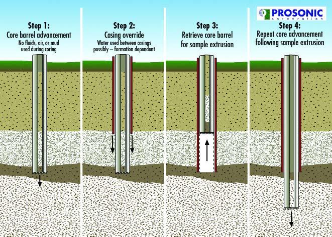
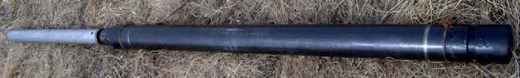
17 Sonic Drilling Faster speed (2-3x) Better core recovery Less waste (70-80%) Up to 12 core Up to 500 deep No drilling mud Less collapse problems Boart Longyear rig 17

18 Rotosonic Video 18


19 Home Depot Other Tools Test pits (backhoe, bulldozer) Hand dug test pits Hand Augers Portable powered auger Franklin Horizontal Drilling Horizontal drilling in rock Horizontal drains and tiebacks Ditch Witch Coil tubing drilling 19


20 Ditch Witch Coil Tubing Drilling 20
21 Drilling Fluids/Stabiliztion Water stabilization Drilling mud Air stabilization Casing stabilization Grout stabilization Freezing Stabilization Soil Sampling Disturbed Samples Wash sampling Auger cuttings Bulk Modified California Split spoon Undisturbed Samples Thin walled sampling tube (Shelby Tube) Piston sampler Bishop sand sampler Continuous push (Geoprobe) Pitcher Denison Block Core barrel (rock) 21

22 Undisturbed Sampling ASCE FHWA NHI

23 Split Spoon FHWA NHI
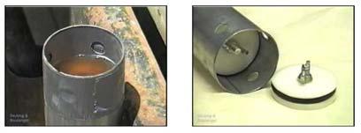
24 Thin Walled Samplers/Shelby Tube FHWA NHI Sampling tools inside augers 24


25 Piston Samplers FHWA NHI Osterberg sampler 25

26 Mechanical Stationary Piston Sampler Retractable Piston Sampler 26


27 Hydraulic Piston Sampler Bishop Sand Sampler 27

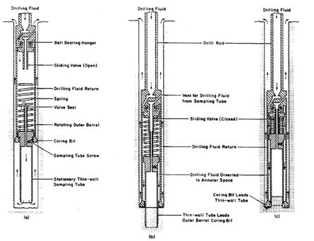
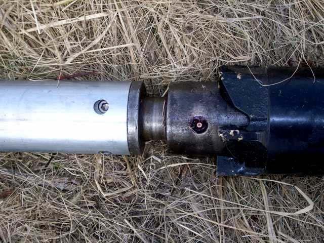
28 Pitcher Tube FHWA NHI Pitcher Tube Sampler 28

 29")
29 Insitu Tests in Soil FHWA NHI Standard Penetration Test (STP) FHWA NHI
30 Standard Penetration Test (STP) Driven by a 140 lb hammer dropping 30, multiple blows (counts) = standard penetration test Standard Penetration Test (STP) ADVANTAGES DISADVANTAGES Obtain both a sample & a number Simple & Rugged Suitable in many soil types Can perform in weak rocks Available throughout the U.S. Obtain both a sample & a number * Disturbed sample (index tests only) Crude number for analysis Not applicable in soft clays & silts High variability and uncertainty FHWA NHI
 videos")
 FHWA")
31 Standard Penetration Test (STP) videos Cone Penetrometer Test (CPT) FHWA NHI

32 Cone Penetrometer Test (CPT) FHWA NHI Cone Penetrometer Test (CPT) FHWA NHI

33 Cone Penetrometer Test (CPT) ADVANTAGES DISADVANTAGES Fast and continuous profiling Economical and productive Results not operatordependent Strong theoretical basis in interpretation Particularly suitable for soft soils High capital investment Requires skilled operator to run Electronic drift, noise, and calibration No soil samples are obtained Unsuitable for gravel or boulder deposits FHWA NHI Flat Plate Dilatometer (DMT) FHWA NHI

34 Flat Plate Dilatometer (DMT) FHWA NHI Flat Plate Dilatometer (DMT) ADVANTAGES DISADVANTAGES Simple and Robust Repeatable & Operator- Independent Quick and economical Difficult to push in dense and hard materials Primarily relies on correlative relationships Need calibrations for local geologies FHWA NHI
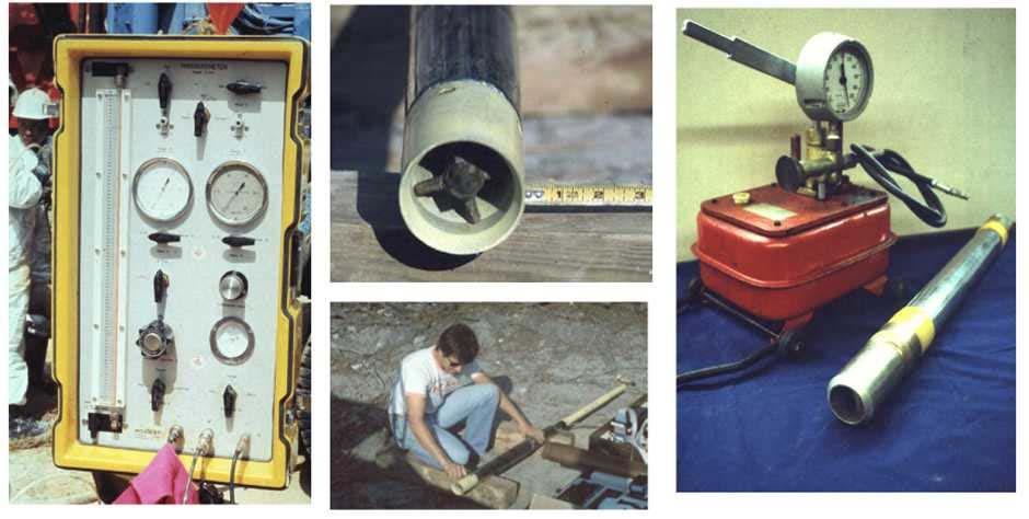
35 Pressuremeter Test (PMT) FHWA NHI

36 Pressuremeter Test (PMT) FHWA NHI Pressuremeter Test (PMT) ADVANTAGES DISADVANTAGES Theoretically sound in determination of soil parameters Tests larger zone of soil mass than other in-situ tests Develop complete σ-ε-τ curve. Complicated procedures; requires high level of expertise in the field Time consuming and expensive (good day gives 6 to 8 complete tests) Delicate, easily damaged FHWA NHI
 FHWA")

37 Vane Shear Test (VST) FHWA NHI Vane Shear Test (VST) FHWA NHI
38 Vane Shear Test (VST) ADVANTAGES DISADVANTAGES Assessment of undrained strength Simple test and equipment Measure in-situ clay sensitivity Long history of use in practice Limited application to soft to stiff clays Slow and time-consuming Raw undrained strength needs (empirical ) correction Can be affected by sand lenses and seams FHWA NHI Downhole Geophysics ADVANTAGES DISADVANTAGES Nondestructive and/or noninvasive Fast and economical testing Theoretical basis for interpretation Applicable to soils and rocks No samples or direct physical penetration Models assumed for interpretation Affected by cemented layers or inclusions Results influenced by water, clay, & depth FHWA NHI

39 Relevance of In-situ Tests to Different Soil Types FHWA NHI Obstructions 39

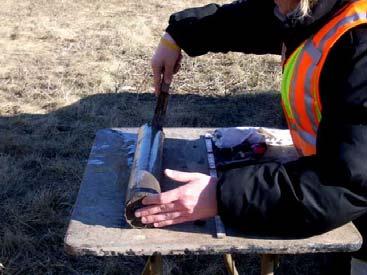

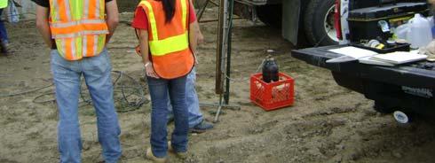
40 Taking samples (extruding from Shelby Tube) Cutting the sample 40


41 Cutting a sample to testing size Testing a sample with Torvane 41


42 Sample Preservation Clearly, permanently and accurately labeled, and position recorded on drill log Sealed against moisture loss if appropriate Put in appropriate container/box Not left in unattended vehicles to freeze or over heat, taken to office/lab in a timely fashion Waxing samples 42
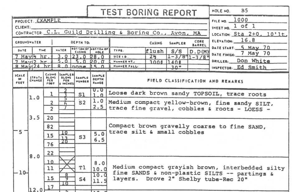
 Boring (hole) number b) Start and finish date c) Name of driller and logger d) Elevation at top of hole e) Depth of hole and reason for")
43 AASHTO Man Sub Inv Boring Logs 1. Description and classification of each layer of soil 2. Depth for each 3. Depths and results of field tests 4. Information a) Boring (hole) number b) Start and finish date c) Name of driller and logger d) Elevation at top of hole e) Depth of hole and reason for terminatioin 43
44 Boring Logs f. Diameter of any casing used g. Size of hammer and free fall distance h. Blows per 0.3 m i. Description and size of sampler j. Size of drive hammer and free fall distance k. Blow count (SPT) each 150 mm drive of sampler l. Type of drilling machine used m. Drilling time for each core run n. Sample recovery o. Project identification p. Client name Boring Logs 5. Notes regarding any other pertinent info a) Dept of observed groundwater, time, conditions b) Artesian condition c) Obstructions d) Drilling difficulties (caving, coring boulders, surging of sands, caverns) e) Loss of circulation f) Drilling mud and casing as needed g) Odor of sample 6. Any other information required 44
45 45
46 Borehole Sealing Cement grout from the bottom Bentonite Remove casing Bad Actors Organic Soils Normally consolidated clays Metastable soils (loess, alluvial, mud flows) Caliche Expansive soils Loose granular soils Sensitive clays 46
47 Bad Actors Noxious or explosive gasses Slope movements Kettle holes Meander loops and cutoffs Artificial fill Karst Weathered shale Abandoned mines Frozen soils SLIDE SHOW: Geological Environments 47


48 Fluvial / Breccia Images from Monro and Wicander Fluvial Variability Images from Monro and Wicander 48


49 Braided River / Point Bars Images from Monro and Wicander Oxbow Meanders Images from Monro and Wicander 49


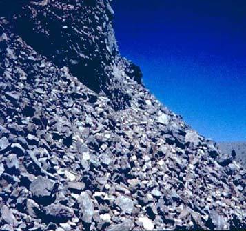
50 River Terrace / Delta Images from Monro and Wicander Aluvial Fans / Talus Images from Monro and Wicander 50


51 Glacial Variability Images from Monro and Wicander 51


52 Till / Moraine Eskers Images from Monro and Wicander 52


53 Esker Cross section of an esker 53


54 Outwash Images from Monro and Wicander Buried Valleys 54


55 Beach Deposit Images from Monro and Wicander Raised beach ridges 55

")


56 Raised beach ridges (air photo) Aolean: Desert Pavements Images from Monro and Wicander 56


57 Desert Pavement Images from Monro and Wicander Salt Flats / Dunes Images from Monro and Wicander 57


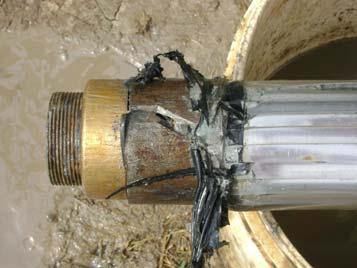
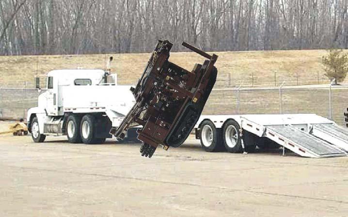
58 Tropical Regions: Weathering Products Images from Monro and Wicander Drilling gone wrong 58
59 59
Instructional Objectives
 GE 343 SUBSURFACE EXPLORATION CH 8 Rock Drilling, Testing, and Sampling Text Ch. 7. Dr. Norbert H. Maerz Missouri University of Science and Technology (573) 341-6714 norbert@mst.edu Instructional Objectives
Rotary Drilling Rotary Drilling Bits
 GE 343 SUBSURFACE EXPLORATION CH 8 Rock Drilling, Testing, and Sampling Text Ch. 7. Dr. Norbert H. Maerz Missouri University of Science and Technology (573) 341-6714 norbert@mst.edu Instructional Objectives
Boreholes. Implementation. Boring. Boreholes may be excavated by one of these methods: 1. Auger Boring 2. Wash Boring 3.
 Implementation Boreholes 1. Auger Boring 2. Wash Boring 3. Rotary Drilling Boring Boreholes may be excavated by one of these methods: 4. Percussion Drilling The right choice of method depends on: Ground
Chapter 12 Subsurface Exploration
 Page 12 1 Chapter 12 Subsurface Exploration 1. The process of identifying the layers of deposits that underlie a proposed structure and their physical characteristics is generally referred to as (a) subsurface
Gotechnical Investigations and Sampling
 Gotechnical Investigations and Sampling Amit Prashant Indian Institute of Technology Gandhinagar Short Course on Geotechnical Investigations for Structural Engineering 12 14 October, 2017 1 Purpose of
ENCE 3610 Soil Mechanics. Site Exploration and Characterisation Field Exploration Methods
 ENCE 3610 Soil Mechanics Site Exploration and Characterisation Field Exploration Methods Geotechnical Involvement in Project Phases Planning Design Alternatives Preparation of Detailed Plans Final Design
SITE INVESTIGATION 1
 SITE INVESTIGATION 1 Definition The process of determining the layers of natural soil deposits that will underlie a proposed structure and their physical properties is generally referred to as site investigation.
SCOPE OF INVESTIGATION Simple visual examination of soil at the surface or from shallow test pits. Detailed study of soil and groundwater to a
 Lecture-5 Soil Exploration Dr. Attaullah Shah 1 Today s Lecture Purpose of Soil Exploration Different methods 1. Test trenches and Pits 2. Auger and Wash Boring 3. Rotary Drilling 4. Geophysical Methods
Manual on Subsurface Investigations National Highway Institute Publication No. FHWA NHI Federal Highway Administration Washington, DC
 Manual on Subsurface Investigations National Highway Institute Publication No. FHWA NHI-01-031 Federal Highway Administration Washington, DC Geotechnical Site Characterization July 2001 by Paul W. Mayne,
KDOT Geotechnical Manual Edition. Table of Contents
 KDOT Geotechnical Manual 2007 Edition The KDOT Geotechnical Manual is available two volumes. Both volumes are very large electronic (pdf) files which may take several minutes to download. The table of
10. GEOTECHNICAL EXPLORATION PROGRAM
 Geotechnical site investigations should be conducted in multiple phases to obtain data for use during the planning and design of the tunnel system. Geotechnical investigations typically are performed in
Module 1 : Site Exploration and Geotechnical Investigation
 Objectives In this section you will learn the following Displacement borings Wash boring Auger boring Rotary drilling Percussion drilling Continuous sampling Boring methods of exploration The boring methods
How to Interpret Mining Company Drill Reports & Announcements
 How to Interpret Mining Company Drill Reports & Announcements A Simple Guide amscot Stockbroking Pty Ltd A division of State One Stockbroking Ltd (AFSL 247 100) Disclaimer: All information in this document
June 9, R. D. Cook, P.Eng. Soils Engineer Special Services Western Region PUBLIC WORKS CANADA WESTERN REGION REPORT ON
 PUBLIC WORKS CANADA WESTERN REGION REPORT ON GEOTECHNICAL INVESTIGATION PROPOSED MARTIN RIVER BRIDGE MILE 306.7 MACKENZIE HIGHWAY Submitted by : R. D. Cook, P.Eng. Soils Engineer Special Services Western
Week 3 : (3HL) Coverage : Typical geotechnical problems and usual application of SI methods
 Coverage : Typical geotechnical problems and usual application of SI methods") LEARNING OUTCOMES Week 3 : (3HL) Coverage : Typical geotechnical problems and usual application of SI methods Learning Outcomes : At the end of this lecture/week, the students will be able to : 1. Discuss
LEARNING OUTCOMES Week 3 : (3HL) Coverage : Typical geotechnical problems and usual application of SI methods Learning Outcomes : At the end of this lecture/week, the students will be able to : 1. Discuss
B-1 BORE LOCATION PLAN. EXHIBIT Drawn By: 115G BROOKS VETERINARY CLINIC CITY BASE LANDING AND GOLIAD ROAD SAN ANTONIO, TEXAS.
 N B-1 SYMBOLS: Exploratory Boring Location Project Mngr: BORE LOCATION PLAN Project No. GK EXHIBIT Drawn By: 115G1063.02 GK Scale: Checked By: 1045 Central Parkway North, Suite 103 San Antonio, Texas 78232
Chapter 3 SUBSOIL EXPLORATION. Omitted parts: Sections & 3.24, 3.25 Examples 3.3, 3.4,3.5
 Chapter 3 SUBSOIL EXPLORATION Omitted parts: Sections 3.2-3.10 & 3.24, 3.25 Examples 3.3, 3.4,3.5 GENERAL OBSERVATION Soil does not posses a unique or linear stress-strain relationship. Soil behavior depends
The process of determining the layers of natural soil deposits that will underlie a proposed structure and their physical properties is generally
 The process of determining the layers of natural soil deposits that will underlie a proposed structure and their physical properties is generally referred to as sub surface investigation 2 1 For proper
 UNIT I SITE INVESTIGATION AND SELECTION OF FOUNDATION Types of boring 1.Displacement borings It is combined method of sampling & boring operation. Closed bottom sampler, slit cup, or piston type is forced
APPENDIX C HYDROGEOLOGIC INVESTIGATION
 Figure B-5.7 Figure B-5.8 Preliminary Geotechnical and Environmental Report Appendix C Hydrogeologic Investigation APPENDIX C HYDROGEOLOGIC INVESTIGATION December 21, 2011 WESTSIDE SUBWAY EXTENSION PROJECT
Table of Contents 8.1 GENERAL Overview Subsurface Exploration Methods Responsibilities... 8.
 Table of Contents Section Page 8.1 GENERAL... 8.1-1 8.1.1 Overview... 8.1-1 8.1.2 Subsurface Exploration Methods... 8.1-2 8.1.3 Responsibilities... 8.1-3 8.1.3.1 Geotechnical Section... 8.1-3 8.1.3.2 District
Geotechnical Geotechnical Assessment
 Site Investigation Site Investigation Pile Probing Pile Probing Geotechnical Logging Geotechnical and Sampling Logging and Sampling Streetworks and Utilities Streetworks Avoidance and Utilities Avoidance
Site Investigations and Geotechnical Risk For Underground Construction Greg Raines, PE
 August 14, 2017 Site Investigations and Geotechnical Risk For Underground Construction Greg Raines, PE Gregory.Raines@Stantec.com Develop Preliminary Geologic / Geotech Conceptual Model for the Project
Regional Structure - Global Centers
 October 22, 2009 Regional Structure - Global Centers Boart Longyear Europe (BLE) Salt Lake City Burghaun Boart Longyear Americas (BLA) Peru Sandton Boart Longyear Far East (BLFE) Adelaide Boart Longyear
Conventional Field Testing & Issues (SPT, CPT, DCPT, Geophysical methods)
") Conventional Field Testing & Issues (SPT, CPT, DCPT, Geophysical methods) Ajanta Sachan Assistant Professor Civil Engineering IIT Gandhinagar Conventional Field Testing 1 Field Test: In-situ shear strength
Conventional Field Testing & Issues (SPT, CPT, DCPT, Geophysical methods) Ajanta Sachan Assistant Professor Civil Engineering IIT Gandhinagar Conventional Field Testing 1 Field Test: In-situ shear strength
SI Planning & Laboratory Testing for Hill-Site Development
 SI Planning & Laboratory Testing for Hill-Site Development 21 April 2009 IEM Penang Ir. Tan Yean Chin G&P Geotechnics Sdn Bhd Cameron Highlands, 1961 Genting Highland Tower 1993 Bukit Antarabangsa, 1999
Depth (ft) USCS Soil Description TOPSOIL & FOREST DUFF
 USCS Soil Description TOPSOIL & FOREST DUFF") Test Pit No. TP-6 Location: Latitude 47.543003, Longitude -121.980441 Approximate Ground Surface Elevation: 1,132 feet Depth (ft) USCS Soil Description 0 1.5 1.5 5.0 SM 5.0 8.0 SM Loose to medium dense,
Test Pit No. TP-6 Location: Latitude 47.543003, Longitude -121.980441 Approximate Ground Surface Elevation: 1,132 feet Depth (ft) USCS Soil Description 0 1.5 1.5 5.0 SM 5.0 8.0 SM Loose to medium dense,
GEOTECHNICAL POLICIES AND PROCEDURES MANUAL CHAPTER 5 GEOTECHNICAL INVESTIGATION PLANNING GUIDELINES
 GEOTECHNICAL POLICIES AND PROCEDURES MANUAL CHAPTER 5 GEOTECHNICAL INVESTIGATION PLANNING GUIDELINES GEOTECHNICAL INVESTIGATION PLANNING GUIDELINES 5-i TABLE OF CONTENTS 1. PURPOSE... 1 2. INTRODUCTION...
East Land Quality Forum Drilling Techniques; Old and New
 East Land Quality Forum Drilling Techniques; Old and New 1 Introduction Different Drilling Methods Rota-sonic drilling What is it and how does it work? Different types of Rota-Sonic/Sonic Drilling Rigs
Underground Risk Management Course Marina Del Rey, California November, Geotechnical Data Reports. Greg Raines, PE
 Underground Risk Management Course Marina Del Rey, California November, 2018 Geotechnical Data Reports Greg Raines, PE Gregory.Raines@Stantec.com Introduction What is a Geotechnical Data Report? The GDR
SASKATCHEWAN STRATIGRAPHY GLACIAL EXAMPLE BOULDERS IN GLACIAL DEPOSITS
 SASKATCHEWAN STRATIGRAPHY GLACIAL EXAMPLE BOULDERS IN GLACIAL DEPOSITS 51 SASKATCHEWAN STRATIGRAPHY GLACIAL SURFICIAL STRATIFIED DEPOSITS 52 SASKATCHEWAN STRATIGRAPHY GLACIAL EXAMPLE OF SEDIMENT DEPOSITION
CHAPTER 3.0 DRILLING AND SAMPLING OF SOIL AND ROCK
 HAPTER 3.0 DRILLING AND SAMPLING OF SOIL AND ROK This chapter describes the equipment and procedures commonly used for the drilling and sampling of soil and rock. The methods addressed in this chapter
OBJECTIVES OF SUBSURFACE EXPLORATION
 OBJECTIVES OF SUBSURFACE EXPLORATION Three (3) General Objectives for Subsurface Exploration: 1. Define Soil and Rock Stratigraphy and Structure within Proposed Construction Zone of Influence. 2. Obtain
Geotechnical Investigation Juneau Seawalk - Taku Fisheries to Miner s Wharf Juneau, Alaska DM&A Job No
 Duane Miller & Associates 5821 Arctic Boulevard, Suite A Anchorage, AK 99518-1654 (907) 644-3200 Fax 644-0507 Arctic & Geotechnical Engineering May 4, 2006 Tetra Tech/KCM, Inc. 1971 First Avenue Seattle,
Geotechnical Testing Methods I
 Geotechnical Testing Methods I Ajanta Sachan Assistant Professor Civil Engineering IIT Gandhinagar Hiding World of Geotechnical Engg!! Foundations Shoring Tunneling Soil Exploration Geotechnical Engg Structures
CHAPTER 3 PLANNING A SUBSURFACE INVESTIGATION AND LABORATORY TESTING PROGRAM
 CHAPTER 3 PLANNING A SUBSURFACE INVESTIGATION AND LABORATORY TESTING PROGRAM 3.1 INTRODUCTION To evaluate soil and rock properties required for geotechnical design related to transportation projects, subsurface
An Introduction to Field Explorations for Foundations
 An Introduction to Field Explorations for Foundations J. Paul Guyer, P.E., R.A. Paul Guyer is a registered mechanical engineer, civil engineer, fire protection engineer and architect with over 35 years
 Photo 1 - Southerly view across 2700 parking lot toward existing building. Multi-residential building borders western side of property in upper right of view. Photo 2 - Southerly view across 2750 parking
Soil Mechanics Brief Review. Presented by: Gary L. Seider, P.E.
 Soil Mechanics Brief Review Presented by: Gary L. Seider, P.E. 1 BASIC ROCK TYPES Igneous Rock (e.g. granite, basalt) Rock formed in place by cooling from magma Generally very stiff/strong and often abrasive
The attitude he maintains in his relation to the engineer is very well stated in his own words:
 Su bsurface Soil Exploration, 53: 139 Foundation Engineering Geotechnical companies that have a history of experience in a given region usually have extensive boring logs and maps telling where the borings
INTRODUCTION TO STATIC ANALYSIS PDPI 2013
 INTRODUCTION TO STATIC ANALYSIS PDPI 2013 What is Pile Capacity? When we load a pile until IT Fails what is IT Strength Considerations Two Failure Modes 1. Pile structural failure controlled by allowable
Enhanced In-Situ Testing for Geotechnical Site Characterization. Graduate Course CEE 6423
 Enhanced In-Situ Testing for Geotechnical Site Characterization SPT, VST, DMT, PMT, CHT, DHT, CPT Graduate Course CEE 6423 Paul W. Mayne, PhD, P.E. Professor, Geosystems Program Civil & Environmental Engineering
Horizontal Directional Drilling: An Approach to Design and Construction. Presenter: John Briand, PE Co-Author: Danielle Neamtu, PE
 Horizontal Directional Drilling: An Approach to Design and Construction Presenter: John Briand, PE Co-Author: Danielle Neamtu, PE Presentation Outline General HDD overview Conceptual-level evaluation Detailed
SITE CHARACTERIZATION
 SITE CHARACTERIZATION Part 2. Intrusive Investigation Technologies Tyler E. Gass, CPG Tetra Tech, Inc. Louisville, CO SITE CHARACTERIZATION INTRUSIVE TECHNOLOGIES Defining the Objectives of the Investigation
APPENDIX C. Borehole Data
 APPENDIX C Borehole Data MAJOR DIVISIONS SOIL CLASSIFICATION CHART SYMBOLS GRAPH LETTER TYPICAL DESCRIPTIONS ADDITIONAL MATERIAL
Early Exploration Permit Activity Information
 Early Exploration Permit Activity Information Activities That Require an Early Exploration Permit: Line cutting that is a width greater than 1.5 metres Mechanized stripping of a total surface area of greater
Instructional Objectives
 GE 6477 DISCONTINUOUS ROCK 8. Fracture Detection Dr. Norbert H. Maerz Missouri University of Science and Technology (573) 341-6714 norbert@mst.edu Instructional Objectives 1. List the advantages and disadvantages
From - To 0,00-4,90 4,90-6,40 6,40-8,60 8,60-9,60 9,60-10,50 10,50-12,00 12,00-14,80 14,80-15,80 15,80-19,30 19, ,00
 Závěrka 12,Praha 6,169 00 Log of Boring BH1 Project ID: 2018_A-017 Annex no.: A.1G Drilling equipment: Hütte 202 TF Location: Prague 12 Overall depth: 2 m Borehole position: Date start: 22.11.2017 Foreman:
Geotechnical Engineering Report
 Geotechnical Engineering Report Turner Turnpike Widening Polecat Creek Bridge (Bridge A) June 1, 2016 Terracon Project No. 04155197 Prepared for: Garver, LLC Prepared by: Terracon Consultants, Inc. TABLE
3.0 SUMMARY OF FINDINGS
 AECOM 500 W Jefferson St. Suite 1600 Louisville, KY 40202 www.aecom.com 502-569-2301 tel 502-569-2304 fax October 17, 2018 Big Rivers Electric Corporation Sebree Generating Station 9000 Highway 2096 Robards,
CHARACTERIZATION OF SOFT CLAY- A CASE STUDY AT CRANEY ISLAND
 National Defense Industrial Association 2005 Tri-Service Infrastructure Systems Conference and Exhibition Re-Energizing Engineering Excellence CHARACTERIZATION OF SOFT CLAY- A CASE STUDY AT CRANEY ISLAND
REPORT OF SUBSURFACE EXPLORATION
 REPORT OF SUBSURFACE EXPLORATION GRAND RIVER DAM AUTHORITY HULBERT 69 KV SWITCHING STATION S. 440 Road Hulbert, Cherokee County, Oklahoma ENERCON PROJECT NO. GRDA006 MARCH 7, 2012 PREPARED FOR: C/O ENERCON
Advanced Foundation Engineering
 2013 Advanced Foundation Engineering Prof.T.G. Sitharam Indian Institute of Science, Bangalore CHAPTER 1: Soil Exploration 1.1 Introduction 1.2 Boring of Holes 1.2.1 Auger Method 1.2.1.1 Hand Operated
MUDLOGGING, CORING, AND CASED HOLE LOGGING BASICS COPYRIGHT. Coring Operations Basics. By the end of this lesson, you will be able to:
 LEARNING OBJECTIVES MUDLOGGING, CORING, AND CASED HOLE LOGGING BASICS Coring Operations Basics By the end of this lesson, you will be able to: Understand why cores are justified and who needs core data
M E M O R A N D U M. Mr. Jonathan K. Thrasher, P.E., Mr. Ian Kinnear, P.E. (FL) PSI
 PSI") M E M O R A N D U M TO: FROM: Mr. Mark Schilling Gulf Interstate Engineering Mr. Jonathan K. Thrasher, P.E., Mr. Ian Kinnear, P.E. (FL) PSI DATE: November 11, 2014 RE: Summary of Findings Geotechnical
M E M O R A N D U M TO: FROM: Mr. Mark Schilling Gulf Interstate Engineering Mr. Jonathan K. Thrasher, P.E., Mr. Ian Kinnear, P.E. (FL) PSI DATE: November 11, 2014 RE: Summary of Findings Geotechnical
General. DATE December 10, 2013 PROJECT No TO Mary Jarvis Urbandale/Riverside South Development Corporation
 DATE December 10, 201 PROJECT No. 10-1121-0260- TO Mary Jarvis Urbandale/Riverside South Development Corporation CC Justin Robitaille, Urbandale Jonathan Párraga, J.L. Richards & Associates Limited FROM
ATTACHMENT A PRELIMINARY GEOTECHNICAL SUMMARY
 ATTACHMENT A PRELIMINARY GEOTECHNICAL SUMMARY Kevin M. Martin, P.E. KMM Geotechnical Consultants, LLC 7 Marshall Road Hampstead, NH 0384 603-489-6 (p)/ 603-489-8 (f)/78-78-4084(m) kevinmartinpe@aol.com
EROSION AND DEPOSITION
 CHAPTER 8 EROSION AND DEPOSITION SECTION 8 1 Changing Earth s Surface (pages 252-255) This section explains how sediment is carried away and deposited elsewhere to wear down and build up Earth s surface.
CONTENTS. 1. GeneralsG Field Investigation WorkG Laboratory Testing Work Surface Soil Description-- 7.
 CONTENTS Page 1. GeneralsG 4 2. Field Investigation WorkG 4 3. Laboratory Testing Work--- 5 4. Surface Soil Description-- 7 Appendix A Borehole Location Plan 11 Soil Profile-- 15 Bore Logs--=---- 18 Appendix
Laboratory Testing Total & Effective Stress Analysis
 SKAA 1713 SOIL MECHANICS Laboratory Testing Total & Effective Stress Analysis Prepared by: Dr. Hetty Mohr Coulomb failure criterion with Mohr circle of stress 2 ' 2 ' ' ' 3 ' 1 ' 3 ' 1 Cot Sin c ' ' 2
Early Exploration Plan Activity Information
 Early Exploration Plan Activity Information Activities That Require an Early Exploration Plan: Line cutting that is a width of 1.5 metres or less; Geophysical surveys on the ground requiring the use of
PRELIMINARY GEOTECHNICAL ENGINEERING REPORT. Proposed Re-Development 44 Old Worcester Road Charlton, Massachusetts. Prepared For:
 PRELIMINARY GEOTECHNICAL ENGINEERING REPORT Proposed Re-Development 44 Old Worcester Road Charlton, Massachusetts Prepared For: Meridian Associates, Inc. 500 Cummings Center, Suite 5950 Beverly, Massachusetts
APPENDIX F CORRELATION EQUATIONS. F 1 In-Situ Tests
 APPENDIX F 1 APPENDIX F CORRELATION EQUATIONS F 1 In-Situ Tests 1. SPT (1) Sand (Hatanaka and Uchida, 1996), = effective vertical stress = effective friction angle = atmosphere pressure (Shmertmann, 1975)
Geotechnical Engineering Report
 Geotechnical Engineering Report Turner Turnpike Widening Bridge B Bridge Crossing: South 257 th West Avenue Creek County, Oklahoma June 1, 2016 Terracon Project No. 04155197 Prepared for: Garver, LLC Tulsa,
Liquefaction Resistance and Internal Erosion Potential of Non-Plastic Silty Sand
 Liquefaction Resistance and Internal Erosion Potential of Non-Plastic Silty Sand Jing-Wen CHEN 1, Wei F. LEE 2, Chun-Chi CHEN 3 1 Professor, Department of Civil Engineering, National Chen-Kung University
Remediation of Soft Clay Utilizing the Dry Mix Method. of Batavia, New York to its discharge into the Niagara River at Tonawanda, New York.
 Introduction Tonawanda Creek meanders as it flows in a generally westerly direction from its headwaters east of Batavia, New York to its discharge into the Niagara River at Tonawanda, New York. The geologic
 SOIL CLASSIFICATION CHART COARSE-GRAINED SOILS MORE THAN 50% RETAINED ON NO.200 SIEVE FINE-GRAINED SOILS 50% OR MORE PASSES THE NO.200 SIEVE PRIMARY DIVISIONS GRAVELS MORE THAN 50% OF COARSE FRACTION RETAINED
Safe bearing capacity evaluation of the bridge site along Syafrubesi-Rasuwagadhi road, Central Nepal
 Bulletin of the Department of Geology Bulletin of the Department of Geology, Tribhuvan University, Kathmandu, Nepal, Vol. 12, 2009, pp. 95 100 Safe bearing capacity evaluation of the bridge site along
Soils. Technical English - I 10 th week
 Technical English - I 10 th week Soils Soil Mechanics is defined as the branch of engineering science which enables an engineer to know theoretically or experimentally the behavior of soil under the action
Role of the Geotechnical Consultant in Design Build Projects a General Contractors Geotechnical Engineer s Perspective
 Role of the Geotechnical Consultant in Design Build Projects a General Contractors Geotechnical Engineer s Perspective Steven R. Saye Kiewit Engineering Group, Inc. Design Build Geotechnical Goal All parties
Chapter 2. Wearing Down Landforms: Rivers and Ice. Physical Weathering
 Chapter 2 Wearing Down Landforms: Rivers and Ice Physical Weathering Weathering vs. Erosion Weathering is the breakdown of rock and minerals. Erosion is a two fold process that starts with 1) breakdown
ENGINEERING ASSOCIATES
 July 16, 211 Vista Design, Inc. 11634 Worcester Highway Showell, Maryland 21862 Attention: Reference: Dear Mr. Polk: Mr. Richard F. Polk, P.E. Geotechnical Engineering Report Charles County RFP No. 11-9
CENTRAL REGION GEOHAZARDS RISK ASSESSMENT SITE INSPECTION FORM
 SITE NUMBER AND NAME C55 H861:02 Slide LEGAL DESCRIPTION NW 14-40-14-W4 CENTRAL REGION GEOHAZARDS RISK ASSESSMENT SITE INSPECTION FORM HIGHWAY & KM NAD 83 COORDINATES N 5811217 E 437291 PREVIOUS INSPECTION
NEW DOWN-HOLE PENETROMETER (DHP-CIGMAT) FOR CONSTRUCTION APPLICATIONS
 FOR CONSTRUCTION APPLICATIONS") NEW DOWN-HOLE PENETROMETER (DHP-CIGMAT) FOR CONSTRUCTION APPLICATIONS 1 2 C. Vipulanandan 1, Ph.D., M. ASCE and Omer F. Usluogullari 2 Chairman, Professor, Director of Center for Innovative Grouting Materials
NEW DOWN-HOLE PENETROMETER (DHP-CIGMAT) FOR CONSTRUCTION APPLICATIONS 1 2 C. Vipulanandan 1, Ph.D., M. ASCE and Omer F. Usluogullari 2 Chairman, Professor, Director of Center for Innovative Grouting Materials
14 Geotechnical Hazards
 Volume 2: Assessment of Environmental Effects 296 14 Geotechnical Hazards Overview This Chapter provides an assessment of the underlying geotechnical conditions to identify: any potential liquefaction
GEOTECHNICAL REPORT. Matanuska-Susitna Borough. Parks Highway Connections Museum Drive. Matanuska-Susitna Borough, Alaska.
 Matanuska-Susitna Borough GEOTECHNICAL REPORT Parks Highway Connections Museum Drive Matanuska-Susitna Borough, Alaska March 2, 20 Prepared By: John Thornley, PE Geotechnical Engineer 333 Arctic Blvd.,
Preliminary Investigation to Eliminate Soft Spots + (Remediation of Soft Subgrade)
") Preliminary Investigation to Eliminate Soft Spots + (Remediation of Soft Subgrade) By Jim Coffin, P.G. Chief Engineering Geologist Wyoming Department of Transportation WYDOT Geology Crew: 24 Total- 1 Admin.
Preliminary Investigation to Eliminate Soft Spots + (Remediation of Soft Subgrade) By Jim Coffin, P.G. Chief Engineering Geologist Wyoming Department of Transportation WYDOT Geology Crew: 24 Total- 1 Admin.
This document downloaded from vulcanhammer.net vulcanhammer.info Chet Aero Marine
 This document downloaded from vulcanhammer.net vulcanhammer.info Chet Aero Marine Don t forget to visit our companion site http://www.vulcanhammer.org Use subject to the terms and conditions of the respective
DRILLED DISPLACMENT PILE PERFORMANCE IN COASTAL PLAIN AND RESIDUAL SOILS
 DRILLED DISPLACMENT PILE PERFORMANCE IN COASTAL PLAIN AND RESIDUAL SOILS Presented by: W. Morgan NeSmith, P.E. Berkel & Company Contractors Inc. 770.941.5100 mnesmith@berkelapg.com SC Engineering Conference
LECTURE 10. Module 3 : Field Tests in Rock 3.6 GEOPHYSICAL INVESTIGATION
 LECTURE 10 3.6 GEOPHYSICAL INVESTIGATION In geophysical methods of site investigation, the application of the principles of physics are used to the study of the ground. The soil/rock have different characteristics
Highway Subsurface Exploration
 Highway Subsurface Exploration D. G. S hurig, Research A ssistant E. J. Yoder, Research E ngineer Joint Highway Research Project Purdue University Introduction This paper pertains to the operation and
Civil Engineering, Surveying and Environmental Consulting WASP0059.ltr.JLS.Mich Ave Bridge Geotech.docx
 2365 Haggerty Road South * Canton, Michigan 48188 P: 734-397-3100 * F: 734-397-3131 * www.manniksmithgroup.com August 29, 2012 Mr. Richard Kent Washtenaw County Parks and Recreation Commission 2330 Platt
UAS Student Residence
 General Notes, Abbreviations and Symbols C100 MATCH LINE - SEE SHEET L6 Existing Site Topographic Conditions C101 MATCH LINE - SEE SHEET L5 Existing Site Topographic Conditions C102 DEPTH(FT.) 5 FROZEN
Sonic Drilling Offers Quality Control and Non-destructive Advantages to Geotechnical and Construction Drilling on Sensitive Infrastructure Sites
 Sonic Drilling Offers Quality Control and Non-destructive Advantages to Geotechnical and Construction Drilling on Sensitive Infrastructure Sites John P. Davis Manager, Construction Drilling Services Boart
Mechanical Wave Measurements. Electromagnetic Wave Techniques. Geophysical Methods GEOPHYSICAL SITE CHARACTERIZATION. Mechanical Wave Geophysics
 Geophysical Methods GEOPHYSICAL SITE CHARACTERIZATION Mechanical Wave Measurements Electromagnetic Wave Techniques Mechanical Wave Measurements Crosshole Tests (CHT) Downhole Tests (DHT) Spectral Analysis
NHBRA SOIL LABORATORY SECTION INTERIM REVISED TEST RATES FOR THE MATERIALS LABORATORY
 NHBRA SOIL LABORATORY SECTION INTERIM REVISED TEST RATES FOR THE MATERIALS LABORATORY DATE OF REVISION: ) 10th October 2010 S/N TEST DESCRIPTION UNIT RATE REMARKS 1 Sieve Analysis (wet and dry methods
B-1 SURFACE ELEVATION
 5A 5B LOGGED BY El. S. Bhangoo DRILLING CONTRACTOR Pitcher Drilling DRILLING METHOD Rotary Wash BEGIN DATE 12-14-12 SAMPLER TYPE(S) AND SIZE(S) (ID) SPT, MC BOREHOLE BACKFILL AND COMPLETION COMPLETION
GZA GeoEnvironmental, Inc.
 GZA BORING NO.: GZ-1 SHEET: 1 of 1 PROJECT NO: 9.223. Drilling Co.: Geologic Type of Rig: Skid Boring Location: See Plan H. Datum: See Plan Rig Model: Mudline : Foreman: Ray Eastwood CME -.8 Final Boring
Cone Penetration Testing in Geotechnical Practice
 Cone Penetration Testing in Geotechnical Practice Table Of Contents: LIST OF CONTENTS v (4) PREFACE ix (2) ACKNOWLEDGEMENTS xi (1) SYMBOL LIST xii (4) CONVERSION FACTORS xvi (6) GLOSSARY xxii 1. INTRODUCTION
Erosion and Deposition
 Erosion and Deposition Erosion Sediment natural forces move rock/soil from one place to another. gravity, water, wind, glaciers, waves are causes material moved by erosion Deposition when erosion lays
ISC 5 SELF-BORING PRESSUREMETER TESTS AT THE NATIONAL FIELD TESTING FACILITY, BALLINA 5 9 SEPT 2016
 ISC 5 5 9 SEPT 2016 SELF-BORING PRESSUREMETER TESTS AT THE NATIONAL FIELD TESTING FACILITY, BALLINA Fillippo Gaone James Doherty Susan Gourvenec Centre for Offshore Foundation Systems, UWA School of Civil,
IN SITU SPECIFIC GRAVITY VS GRAIN SIZE: A BETTER METHOD TO ESTIMATE NEW WORK DREDGING PRODUCTION
 IN SITU SPECIFIC GRAVITY VS GRAIN SIZE: A BETTER METHOD TO ESTIMATE NEW WORK DREDGING PRODUCTION Nancy Case O Bourke, PE 1, Gregory L. Hartman, PE 2 and Paul Fuglevand, PE 3 ABSTRACT In-situ specific gravity
Predicting Settlement and Stability of Wet Coal Ash Impoundments using Dilatometer Tests
 Predicting Settlement and Stability of Wet Coal Ash Impoundments using Dilatometer Tests Chris Hardin, P.E. CH2M Hill, Charlotte, North Carolina, E-mail: Chris.Hardin@ch2m.com Roger Failmezger, P.E., F.
patersongroup Design for Earthquakes Consulting Engineers May 19, 2016 File: PG3733-LET.01
 patersongroup May 19, 2016 File: PG3733-LET.01 Hydro Ottawa Limited c/o Cresa Toronto 170 University Avenue, Suite 1 Toronto, Ontario M5H 3B3 Attention: Ms. Barbara Wright Consulting Engineers 154 Colonnade
Limited Geotechnical Engineering Evaluation Classroom Additions Albany County Campus Laramie, Wyoming
 Limited Geotechnical Engineering Evaluation Classroom Additions Albany County Campus 2300 Missile Drive, Cheyenne, Wyoming 82001 Phone 307-635-0222 www.stratageotech.com Limited Geotechnical Engineering
GEOTECHNICAL SITE CHARACTERIZATION
 GEOTECHNICAL SITE CHARACTERIZATION Neil Anderson, Ph.D. Professor of Geology and Geophysics Richard W. Stephenson, P.E., Ph.D. Professor of Civil, Architectural and Environmental Engineering University
Appendix D: Subsurface Investigation
 Independent Expert Engineering Investigation and Review Panel Report on Mount Polley Tailings Storage Facility Breach Appendix D: Subsurface Investigation January 30, 2015 Report on Mount Polley Tailings
What are the different ways rocks can be weathered?
 Romano - 223 What are the different ways rocks can be weathered? Weathering - the breakdown of rocks and minerals at the Earth s surface 1. 2. PHYSICAL WEATHERING Rock is broken into smaller pieces with
DRILL HOLE # BH-BGC13-FN-01
 DILL HOLE # BH-BGC3-FN-0 Drill Method: Mud otary/coring Depth To ock (m): N/A Page of 7 eviewed by: AJB 0 GAVEL (GW) Fine to coarse, sandy, well graded, dense, max particle size = 30 mm, angular to subrounded,
IAEA SAFETY STANDARDS Geotechnical Aspects of Site Evaluation and Foundations in NPPs, NS-G-3.6
 IAEA SAFETY STANDARDS Geotechnical Aspects of Site Evaluation and Foundations in NPPs, NS-G-3.6 Regional Workshop on Volcanic, Seismic, and Tsunami Hazard Assessment Related to NPP Siting Activities and