TECHNICAL MEMORANDUM. SUBJECT: Round 1 Sediment Investigation and Plan for Round 2 Investigation Sparrows Point Phase I Area
|
|
|
- June Mitchell
- 5 years ago
- Views:
Transcription
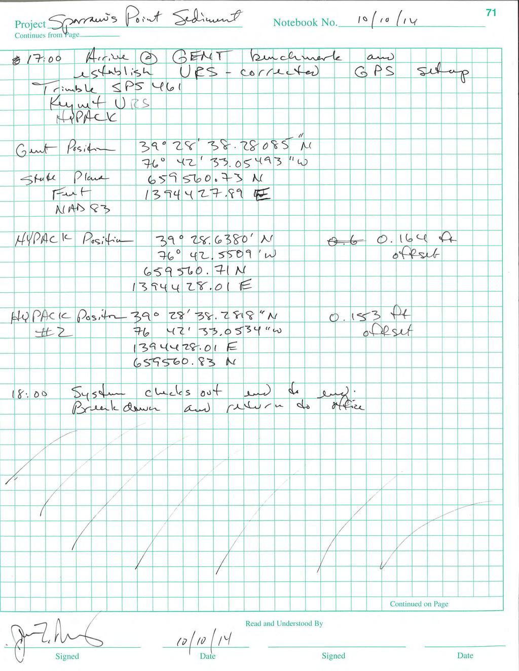
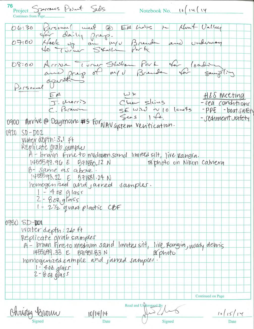
1 EA Engineering, Science, and Technology, Inc., PBC 225 Schilling Circle Hunt Valley, MD Telephone: FAX: January 2015 TECHNICAL MEMORANDUM TO: FROM: Andrew Fan (EPA) Barbara Brown (MDE) Madi Novak (Maul Foster & Alongi, Inc.) Dan Silver (Sparrows Point Environmental Trust) John Morris, Field Lead Samantha Saalfield, Project Geologist Frank Barranco, Project Manager SUBJECT: Round 1 Sediment Investigation and Plan for Round 2 Investigation Sparrows Point Phase I Area Background The Sparrows Point Environmental Trust (the Trust) has contracted EA Engineering, Science, and Technology, Inc., PBC (EA) to plan and implement the Offshore Investigation of the Phase I, Northwest Shoreline study area, adjacent to the Sparrows Point Facility. The first round of sampling for the Offshore Investigation consisted of sediment sampling conducted on 13 and 14 October All work was conducted in accordance with the Work Plan for Offshore Investigation of the Phase I Area of the Sparrows Point Site, dated September 2014, with minor exceptions noted below. The Phase I area is located approximately 6 miles southeast of Baltimore, Maryland, in the vicinity of I-695 and Bear Creek. The Round 1 sediment investigation included sampling within approximately 1,000 feet of the shoreline in the Phase I area. Sampling Locations During the first round of the offshore investigation, surface sediment was collected from 20 locations, along eight transects (A-H) oriented perpendicular to the shoreline. The locations, chosen to provide good spatial coverage of the Phase I area, are listed on Table 1 and illustrated on Figure 1. Note that for locations where more than one Ponar grab sample was needed to yield sufficient volume for the required analyses, Table 1 presents the coordinates of each grab sample taken at the location. Duplicate grab samples were taken within 10 ft of the target location for each sample. Sediment Sampling and Analysis A 23-ft Monark aluminum hull survey boat was launched from the Turner Station Park boat ramp, directly across Bear Creek from the Phase I area. This vessel was chosen for field sampling due to anticipated weather conditions and necessity for space to collect decontamination water and extra
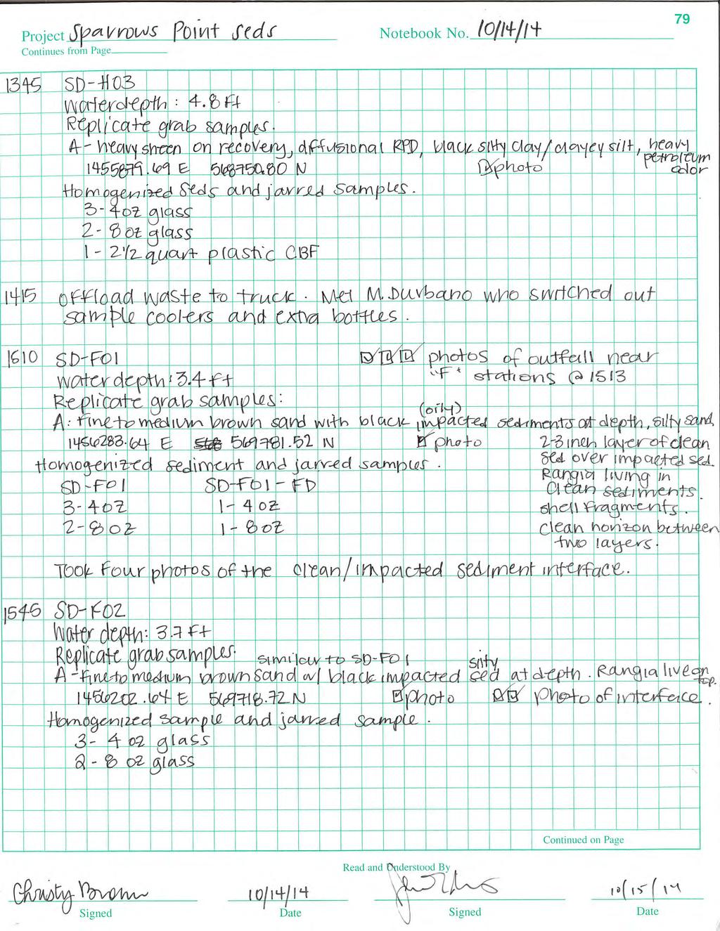
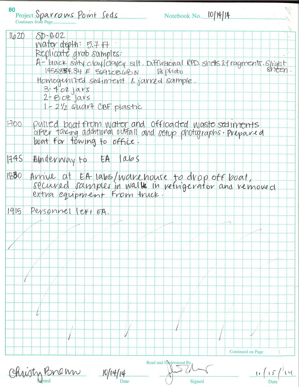
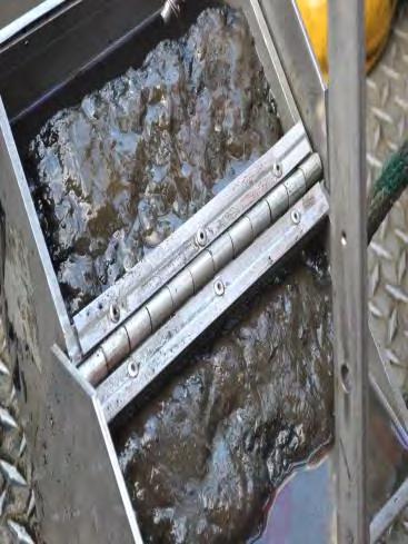
2 14 January 2015 sediment volume for proper disposal. The roving Trimble SPS 461 global positioning system (GPS) receiver was initialized and differential corrections for the satellite positioning data were loaded. The GPS system was connected through HYPACK, and Beacon Marker 5 location was collected as a daily check for the accuracy of the GPS unit. The boat was navigated to each targeted sampling location and surface sediments were collected. Surface sediment samples were collected to approximately 6 inches below the sediment surface using a Ponar grab sampler. If needed, replicate grab samples were collected using the Ponar until adequate volume had been obtained for the required analysis (including volume required for quality control samples and for separate analysis by Chesapeake Bay Foundation [CBF]). Each grab sample was taken within 10 ft of the target location for the sample; Table 1 presents the coordinates of each grab sample. The field logbook documenting the sampling is included in Attachment A, and a photographic log is included in Attachment B. Descriptions of the sediment grab samples collected are also recorded in Table 1. Following collection of the required sample volume, the sample was homogenized using a decontaminated stainless steel spoon in a stainless steel pot and immediately sub-sampled for volatile organic compound (VOC) and simultaneously extracted metals/acid volatile sulfide (SEM/AVS) analysis (as applicable). Note that these sub-samples were not collected prior to homogenization, as indicated in the work plan, because of the heterogeneity within and between Ponar samples at many of the sites (see Table 1 and photographic log, Attachment B). Rather, they were collected expediently following homogenization, and placed in laboratory-cleaned 4- ounce bottles with no headspace. The remainder of the sample was then sub-sampled into appropriate laboratory-cleaned containers using stainless steel sampling tools. Sample processing equipment that came into direct contact with the sediment (e.g., the Ponar sampler and stainless steel pot) was decontaminated according to the protocols specified in the Work Plan. Additional sample volume for the CBF was collected in 2.5-quart plastic containers from the following 11 locations: SD-A02, SD-A03, SD-B02, SD-C02, SD-C03, SD-D02, SD-E02, SD-E03, SD-G02, SD-H01, and SD-H03. These containers were taped to prevent leaking, and stored in a separate cooler from project samples. Unused sediment and decontamination water were containerized in 50-gallon drums, in accordance with the special condition included in Maryland Wetlands License No , under which the Maryland Board of Public Works authorized this sampling on 1 October The containerized material was drummed and transported to a secure offsite staging area. The results of the sediment sampling will be used to characterize the material for disposal. Samples were placed in a cooler with ice to maintain a temperature of <4 0 C, and stored in the cooler until delivery to the laboratory. Two field duplicate samples were collected, from locations SD-B02 and SD-F01, and a trip blank was included in each cooler containing bottles for analyses of VOCs. Two rinsate blanks were also collected after the sampling effort, one from the Ponar sampler and one from the stainless steel pot used to homogenize the samples (note that the analytical results from the rinsate blanks are not yet available). 2
3 14 January 2015 Samples were packaged in bubble wrap, placed in an ice-filled cooler, and shipped via overnight delivery to TestAmerica Pittsburgh in Pittsburgh, Pennsylvania on the day following collection. Coolers were sealed with packing tape and custody seals, and a completed chain-of-custody record representing the packaged samples was taped to the inside of the cooler lid. A representative from the CBF picked up CBF s samples, which had been kept in EA s walk-in refrigerator, on 15 October TestAmerica analyzed sediment samples from each transect for the analytes specified in the Work Plan, with one addition (Table 2): the sample from location C-02 was also analyzed for grain size and moisture content due to the finding of unexpectedly coarse sediment, possibly associated with a washout from the shoreline. The suites of analytes for which samples were analyzed included the following: Priority pollutant list (PPL) VOCs by EPA Method 8260C Low-level (LL) PPL semivolatile organic compounds (SVOCs) by EPA Method 8270D LL Low-level polychlorinated biphenyl (PCB) Aroclors by EPA Method 8082A LL PPL metals by EPA Method 6020A Mercury by EPA Method 7471B Cyanide by EPA Method 9014 Oil and Grease by EPA Method 9071B SEM/AVS by EPA Methods 6010B and 9034 Total Solids by EPA Method SM 2540G Total Organic Carbon (TOC) by Lloyd Kahn Grain Size by ASTM D422 Moisture Content by D Results Tables 3 through 9 present the results of the sediment analyses. Analytical reports have been provided under separate cover and will be retained by EA. Comparison of results for the field duplicates and their parent samples generally indicated acceptable agreement (within approximately 50 percent) when both results were detected. However, the reported concentrations of copper in the parent-duplicate pair from location SD-F01 differed by roughly 100 percent, a reflection of the potential for small-scale heterogeneity during sediment sampling. Contaminants of potential concern (COPCs) detected in laboratory method blanks included chromium, lead, zinc, oil and grease, and toluene. Results for associated samples have been B-qualified. Validated results, with any necessary changes or qualifications, will be used in the risk assessment. Sediments from two transects (B and E), along with the sample from location SD-C02, underwent grain size analysis (Table 3). As expected, the near-shore samples (SD-B01, SD-E01, and SD-E- 01) contained the highest percentages of sand (92.5 percent, 96.8 percent, and 83.4 percent, respectively). The samples from B-02 and E-03 were composed of approximately three-quarters silt and one-quarter sand, with no gravel and only trace amounts of clay. Sample SD-C02, which 3
4 14 January 2015 was added to the grain size analysis due to its unexpectedly coarse composition, was composed of 28.7 percent gravel and 56.6 percent sand. All samples were analyzed for TOC (Table 3), and concentrations ranged from 2,300 mg/kg in the sandy sediments from location E-01 to 180,000 mg/kg in the fine-grained sediments from locations SD-G02 and SD-H03. Figures 2 through 7 present the distribution of the concentrations of selected COPCs in the surface sediment, across the Phase I area. Note that in these figures, results are presented using color-coded concentration ranges to illustrate trends in relative concentrations. The data were also screened against risk-based criteria following review of the draft version of this memorandum by EPA and MDE. The screening methodology and results are summarized in the EPA comments provided in Attachment C. Nickel and zinc were chosen to represent metals in the figures (Figures 2 and 3, Table 4), as they show spatial distribution similar to other metals. The highest concentrations of nickel and zinc (170 mg/kg and 10,000 mg/kg respectively) were reported in sample SD-H03, from the southern end of the Phase I area. Other samples from Transects G and H, as well as samples SD-A03, SD- B02, SD-C03, and SD-E03, also contained elevated metals concentrations. All of these samples were classified as fine-grained (silt and clay). Mercury, which was analyzed in samples from transects A, B, C, F, G, and H, showed the same general trend as other metals, with the highest concentrations in fine-grained sediments farther offshore, up to 0.83 mg/kg in sample SD-H03 (Table 4). Cyanide concentrations showed a similar pattern to the metals (Figure 4, Table 4), with the highest concentration (21 mg/kg) in the sample from SD-G02, and concentrations over 1 mg/kg also in samples from SD-C03, SD-E03, SD-H01, and SD-H02. PAH concentrations exceeded 1,000 µg/kg in at least one sample from each transect except for the D and E transects, with concentrations generally higher farther offshore, where sediment has higher clay and silt content. The highest concentrations of Total PAHs (Figure 5, Table 5) were reported in samples SD-E03, SD-G02, and SD-H03 (10,360, 14,330, and 11,600 µg/kg, respectively). SD- E03 was observed to have a slight odor, SD-G02 had a slight sheen, and SD-H03 had a heavy sheen and heavy petroleum odor. SD-G01 and SD-H01 were also observed to have a heavy petroleum odor with sheen, while SD-H02 had a slight odor with sheen, and SD-G02 had slight sheen but no observed odor. SD-F01 and SD-F02 contained sediment that appeared oily at depths greater than a few inches. A slight odor and sheen were also noted in SD-C03. Bis(2-ethylhexyl)phthalate was the only SVOC detected. The sample from location SD-H03 contained the highest concentration of bis(2-ethylhexyl)phthalate (33,000 µg/kg) (Figure 6, Table 6). Concentrations exceeding 1,000 µg/kg were reported in all samples from the G and H transects, in one sample each from the E and F transects, and in none of the samples collected farther north (although for some samples the reporting limit for this compound exceeded 1,000 µg/kg). 4
5 14 January 2015 Analysis of PCB Aroclors was performed only on samples from transects associated with active stormwater outfalls (B, C, F, G, and H). Concentrations were highest in the H transect and in the sample from SD-F01 (Figure 7, Table 7). The following VOCs were detected in one or more samples (Table 8): 1,2-dichlorobenzene, benzene, chlorobenzene, ethylbenzene, and toluene. Toluene was detected in all samples; however, this analyte was also detected in the laboratory method blanks, at concentrations of a similar order of magnitude (1.17 µg/kg and 1.7 µg/kg). The sample from location SD-H03 was the only sample containing toluene at a concentration (16 µg/kg) approaching 10 times the method blank detections, and therefore the most likely to contain toluene. This sample also had the only detection of benzene (6.9 µg/kg) and the highest detected concentrations of chlorobenzene (250 µg/kg) and ethylbenzene (33 µg/kg). All of the surface sediment samples collected were analyzed for AVS/SEM, to aid with assessment of bioavailability for toxicity (Table 9). Samples from the following locations did not have detectable AVS, so the SEM/AVS ratio could not be calculated: SD-A01, SD-B01, SD-C01, and all samples from the D and E transects. The SEM/AVS ratio for the following locations was equal to or greater than 1, indicating that the metals present in the sediment may be bioavailable: SD- C03, SD-F02, SD-G02, SD-H01, SD-H02, and SD-H03. The highest ratio was 21, in the sample from SD-H03. These results indicate that metals may be bioavailable in the sediments of the Phase I area. To better assess which areas show impacts by groundwater COPCs, the metals and PAH data from Round 1 were normalized to TOC concentrations (Figures 8, 9, and 10). Because coarser-grained sediments, often located near-shore, tend to contain less organic carbon and also contain less surface area for adsorption of constituents such as metals and PAHs, the concentrations of contaminants in these sediments may be diluted out and appear less significant than they are. By normalizing to the TOC concentration, this effect is removed and the possibility of groundwater impacts can be better assessed. In summary of the analytical results, the most elevated concentrations of metals, PAHs, Bis(2- ethylhexyl)pthalate, and PCBs were associated with sediments toward the southern end of the study area, adjacent to the outlet of the Tin Mill Canal. Additionally, an observable trend exists between the elevation of these constituents and grain size; higher concentration associated with finer grained sediments. Considering finer grained sediments are associated with samples further offshore, elevation in concentration of these constituents varies inversely with distance from the shoreline in certain cases. Proposed Sampling Plan for Round 2 Sampling As stated in the Work Plan for the Offshore Investigation, the locations of pore water sampling and additional sediment sampling are to be determined based on the results from the Round 1 sediment investigation. The proposed sampling locations and rationale for their selection are presented below. 5
6 14 January 2015 Pore Water The following criteria were identified for selection of pore water sampling locations: Locations near onshore areas where groundwater COPCs exceeding the BTAG surface water screening criteria by at least five-fold (or consistently exceeding the criteria by twofold) have been identified (Attachment C). Note that if a chemical was not detected from , then any prior exceedances were excluded. However, prior exceedances were taken into account if there were no analyses for the chemical from Sandy locations where pore water upwelling is thought to be likely. The proposed locations for pore water sampling and the rationale for selecting each location are presented in Table 10. The proposed locations are shown on Figure 11. All except one of selected locations (F03) are within approximately 100 feet of the shoreline because this is thought to be the most likely location of groundwater upwelling. This interpretation is based on the underlying geology, which does not include prominent shallow confining layers, as well as the sandy sediment lithology in the near-shore area. The water depth at all of the selected locations is expected to be less than approximately 10 ft. At each of these locations, a pore water sample will be collected using a push-point sampler, from approximately 1 ft below the sediment-water interface. Collection of pore water from this depth will produce data relevant to the biologically active zone for the risk assessment, while minimizing any possible intrusion of surface water from above the sediment-water interface. As stated in the Work Plan, in situ water quality measurements will be used to monitor for potential incursion of surface water, which must be avoided during sampling. Each pore water sample will be analyzed for the COPCs identified in the associated monitoring wells identified in Table 10, and also for dissolved organic carbon (DOC) and magnesium and calcium (to allow calculation of surface water screening criteria) (Table 11). The analytical methods, total numbers of samples to be analyzed, and quality control samples are presented in Table 12. Sediment The following criteria were identified for selection of additional sediment sampling locations: Locations identified for pore water sampling where no sediment sample was collected during Round 1. Locations in the vicinity of Transects G and H, where the lateral and vertical extent of contamination require delineation to support a future Corrective Measures Study for the Phase I area. The proposed locations for Round 2 sediment sampling and the rationale for selecting each location are presented in Table 13. The proposed locations are shown on Figure 11. 6
7 14 January 2015 Surface sediment will be collected from one location identified for pore water analysis, where no sediment sample was collected during Round 1. Surface sediment results from this location will be collected for comparison to pore water. The Round 2 surface sediment samples will be collected using the same methodology as were the Round 1 sediments. Up to 12 sediment cores will be collected from the area of the G and H transects, where high concentrations of oil and grease (up to 11%), observable sheen and petroleum odor, and metals concentrations exceeding sediment PECs were reported in surface sediment. Additionally, two cores, co-located with pore water analyses, will be collected from the F transect, where an oily black sediment layer with 1.5% oil and grease was observed near the shoreline. Although the Work Plan indicated that sediment cores, if required, would be collected using manual push cores to a depth of approximately 2 ft, it was determined based on the Round 1 data that deeper delineation is likely necessary to define the extent of contamination in the targeted area. An electric vibracorer will be deployed from a 28-ft aluminum-hull survey and research vessel and used to advance cores to a penetration depth of 5 to 6 feet below the sediment-water interface or refusal. Upon recovery, the cores will be held at 4 C, transferred to a processing facility, then split, described and photographed. Any observable impacts (sheen and/or odor) will be assessed and recorded. Generally, sediment sub-samples will be generated based on 2-foot intervals below the sediment-water interface (0-2 ft, 2-4 ft, 4-6 ft, etc.). A surface interval sample from every core will be submitted for analysis. If a core has no observable impacts, then the next deeper interval (2-4 ft) will also be submitted for analysis. Alternatively, if multiple intervals in the middle and bottom portions of a core contain observable impacts, then only the lowest of the impacted intervals, and any un-impacted intervals below the lowest impacted interval, will be submitted for laboratory analysis. Each interval will be homogenized using decontaminated stainless steel mixing equipment and transferred to pre-cleaned, 8 ounce jars for analytical testing. Cores from locations F03, F04, G01, G01.5, G02, H01, H02.5, and H03 will be collected and sampled first, followed by cores from locations G03 and H04. If no contamination (sheen or petroleum odor) is apparent in cores G03 and H04 (at the edge of the subaqueous survey area), then no more cores will be sampled. However, if contamination is apparent in these cores, cores will be advanced at locations G04 and H05, and these cores will be sampled as described above. If no contamination (obvious sheen or petroleum odor) is apparent in these cores, then no more cores will be sampled. If contamination is apparent in cores from G04 and H05, then cores will be advanced at locations G05 and H06, and all four of these cores will be sampled as described above. Thus, up to 14 cores may be sampled. For planning purposes, it is assumed that an average of three samples will be collected from each core; however, as described above, only two samples may be required from some cores, based on field observations. The sediment samples will be analyzed for the parameters indicated in Table 14. As in Round 1, the analytical parameters for the surface sediment grab samples are based on whether they are adjacent to an active stormwater outfall. Parameters to be analyzed in sediment core samples were selected based on the primary contaminants identified in the area of the G and H transects, based on Round 1 sampling, and potential historical releases from the Tin Mill Canal. The analytical methods, total numbers of samples to be analyzed, and quality control samples are presented in Table 12. 7
8 14 January 2015 If the findings of the Data Gaps Report, which will be based on the Round 1 and Round 2 results, indicate that the Round 2 coring did not achieve delineation, further expansion of the investigation area and/or use of a barge with larger vibracorer may be considered to obtain deeper cores. 8


9 Document Path: \\lovetonfederal\gisdata\northeast\maryland\sparrowspoint\mxd\phasei_nwshoreline\sp_phasei Figure 1 Sampling Locations for First Round.mxd MD^_ ,200 Feet 1 inch = 1,200 feet Turner Station $ Legend Phase 1 Northwest Shoreline Perennial Creek/Stream Boundary between Sand and Fine Grained Sediment Sediment Sampling Location D Approximate Location of Active Stormwater Outfall Approximate Location of Inactive Stormwater Outfall SD-E03 SD-D01 SD-D02 SD-E01 SD-E02 SD-G02 SD-C03 SD-H03 Greys Landfill Well SD-B02 @A@A SD-F01 SD-F02 SD-B01 SD-C01 SD-A03 SD-H02 Groundwater Well Sampled in SD-A01 RW18-PZM047 RW19-PZM020 RW19-PZM050 RW19-PZP000 TS04-PDM004 RW20-PZP000 HI08-PZM003 SD-H01 Outfall 071 Outfall 070 Outfall HI08-PZM060 Outfall 014 GL-16(-32) GL-15(-36) GL-15(-6) TS-01(-7) GL-02(-5) GL-12(-3) GL-12(-17) Outfall UNNAMED GL-02(-29) GL-05(-7) GL-05(-25) Tin Mill Canal Map Date: January 2015 Image Source: ESRI 2011 Projection: NAD 1983 StatePlane Maryland FIPS 1900 (US Feet) Figure 1 Sampling Locations for the First Round of the Offshore Investigation Phase I Northwest Shoreline Baltimore, Maryland
10 SD-A03 46 mg/kg SD-A02 30 mg/kg SD-A mg/kg Document Path: \\lovetonfederal\gisdata\northeast\maryland\sparrowspoint\mxd\phasei_nwshoreline\sp_phasei Figure 2 Nickel Conc in Seds Rd1.mxd Turner Station Bear Creek SD-E03 76 mg/kg SD-D mg/kg SD-C03 46 mg/kg SD-H mg/kg D SD-F02 10 mg/kg SD-B02 46 mg/kg SD-C mg/kg SD-C mg/kg SD-G mg/kg SD-D mg/kg SD-E mg/kg SD-E mg/kg SD-F01 19 mg/kg SD-H mg/kg SD-B mg/kg SD-G01 63 mg/kg SD-H01 95 mg/kg Tin Mill Canal MD^_ ,000 Feet 1 inch = 1,000 feet $ Legend D Phase 1 Northwest Shoreline Perennial Creek/Stream Boundary between Sand and Fine Grained Sediment Approximate Location of Active Stormwater Outfall Approximate Location of Inactive Stormwater Outfall Nickel in Sediments <10 mg/kg mg/kg mg/kg >100 mg/kg Figure 2 Nickel Concentrations in Sediments from Round 1 Sampling Phase I Northwest Shoreline Baltimore, Maryland Map Date: January 2015 Image Source: ESRI 2011 Projection: NAD 1983 StatePlane Maryland FIPS 1900 (US Feet)
11 SD-A03 1,400 mg/kg SD-A mg/kg SD-A mg/kg Document Path: \\lovetonfederal\gisdata\northeast\maryland\sparrowspoint\mxd\phasei_nwshoreline\sp_phasei Figure 3 Zinc Conc in Seds Rd1.mxd Turner Station Bear Creek SD-D mg/kg SD-E03 1,200 mg/kg SD-C03 1,500 mg/kg SD-G02 1,700 mg/kg SD-H03 10,000 mg/kg D SD-F mg/kg SD-B02 1,600 mg/kg SD-D mg/kg SD-E mg/kg SD-E mg/kg SD-C mg/kg SD-C01 98 mg/kg SD-F mg/kg SD-H02 1,900 mg/kg SD-B01 99 mg/kg SD-G01 1,100 mg/kg SD-H01 1,900 mg/kg Tin Mill Canal MD^_ ,000 Feet 1 inch = 1,000 feet $ Legend D Phase 1 Northwest Shoreline Perennial Creek/Stream Boundary between Sand and Fine Grained Sediment Approximate Location of Active Stormwater Outfall Approximate Location of Inactive Stormwater Outfall Zinc in Sediments <500 mg/kg 500-1,000 mg/kg 1,000-2,000 mg/kg >2,000 mg/kg Figure 3 Zinc Concentrations in Sediments from Round 1 Sampling Phase I Northwest Shoreline Baltimore, Maryland Map Date: January 2015 Image Source: ESRI 2011 Projection: NAD 1983 StatePlane Maryland FIPS 1900 (US Feet)
12 SD-A U mg/kg SD-A U mg/kg SD-A mg/kg Document Path: \\lovetonfederal\gisdata\northeast\maryland\sparrowspoint\mxd\phasei_nwshoreline\sp_phasei Figure 4 Cyanide Conc in Seds Rd1.mxd Turner Station MD^_ ,000 Feet 1 inch = 1,000 feet $ Legend D Bear Creek SD-E mg/kg SD-D mg/kg SD-G02 21 mg/kg SD-H03 12 mg/kg SD-C mg/kg D SD-F mg/kg Phase 1 Northwest Shoreline Perennial Creek/Stream Boundary between Sand and Fine Grained Sediment Approximate Location of Active Stormwater Outfall Approximate Location of Inactive Stormwater Outfall SD-B02 1 U mg/kg SD-E mg/kg SD-E mg/kg SD-D U mg/kg SD-C mg/kg SD-C01 37 U mg/kg SD-F mg/kg SD-H mg/kg SD-B U mg/kg SD-G mg/kg SD-H mg/kg Total Cyanide in Sediments ND <1 mg/kg 1-10 mg/kg >10 mg/kg Tin Mill Canal Figure 4 Total Cyanide Concentrations in Sediments from Round 1 Sampling Phase I Northwest Shoreline Baltimore, Maryland Note: U = Compound was not detected. Value is the reporting limit. Map Date: January 2015 Image Source: ESRI 2011 Projection: NAD 1983 StatePlane Maryland FIPS 1900 (US Feet)
13 SD-A03 1,449 ug/kg SD-A02 2,749 ug/kg SD-A ug/kg Document Path: \\lovetonfederal\gisdata\northeast\maryland\sparrowspoint\mxd\phasei_nwshoreline\sp_phasei Figure 5 PAH Conc in Seds Rd1.mxd Turner Station Bear Creek SD-E03 10,360 ug/kg SD-D ug/kg SD-G02 14,330 ug/kg SD-C03 5,630 ug/kg SD-H03 11,600 ug/kg D SD-F ug/kg SD-B02 2,309 ug/kg SD-E02 61 ug/kg SD-E01 24 ug/kg SD-D01 76 ug/kg SD-C ug/kg SD-C ug/kg SD-F01 1,604 ug/kg SD-H02 5,910 ug/kg SD-B ug/kg SD-G01 2,400 ug/kg SD-H01 2,920 ug/kg Tin Mill Canal MD^_ ,000 Feet 1 inch = 1,000 feet $ Legend D Phase 1 Northwest Shoreline Perennial Creek/Stream Boundary between Sand and Fine Grained Sediment Approximate Location of Active Stormwater Outfall Approximate Location of Inactive Stormwater Outfall Total PAHs in Sediments <10 ug/kg ug/kg 100-6,000 ug/kg >6,000 ug/kg Figure 5 Total PAH Concentrations in Sediments from Round 1 Sampling Phase I Northwest Shoreline Baltimore, Maryland Map Date: January 2015 Image Source: ESRI 2011 Projection: NAD 1983 StatePlane Maryland FIPS 1900 (US Feet)
14 SD-A03 2,900 U ug/kg SD-A ug/kg SD-A01 27 ug/kg Document Path: \\lovetonfederal\gisdata\northeast\maryland\sparrowspoint\mxd\phasei_nwshoreline\sp_phasei Figure 6 BIS Conc in Seds Rd1.mxd Turner Station MD^_ ,000 Feet 1 inch = 1,000 feet $ Legend D Bear Creek SD-E03 3,700 ug/kg SD-D02 29 ug/kg SD-C03 3,500 U ug/kg SD-C02 1,400 U ug/kg SD-G02 13,000 ug/kg SD-H03 33,000 ug/kg D SD-E02 42 ug/kg SD-F ug/kg Phase 1 Northwest Shoreline Perennial Creek/Stream Boundary between Sand and Fine Grained Sediment Approximate Location of Active Stormwater Outfall Approximate Location of Inactive Stormwater Outfall SD-B ug/kg SD-D U ug/kg SD-E01 18 ug/kg SD-F01 1,600 ug/kg SD-H02 3,500 ug/kg SD-B U ug/kg SD-C U ug/kg SD-G01 3,300 ug/kg SD-H01 7,500 ug/kg Bis(2-ethylhexyl)phthalate in Sediments ND <100 ug/kg 100-4,000 ug/kg >4,000 ug/kg Tin Mill Canal Figure 6 Bis(2-ethylhexyl)phthalate Concentrations in Sediments from Round 1 Sampling Phase I Northwest Shoreline Baltimore, Maryland Note: U = Compound was not detected. Value is the reporting limit. Map Date: January 2015 Image Source: ESRI 2011 Projection: NAD 1983 StatePlane Maryland FIPS 1900 (US Feet)
15 SD-A03 SD-A02 SD-A01 Document Path: \\lovetonfederal\gisdata\northeast\maryland\sparrowspoint\mxd\phasei_nwshoreline\sp_phasei Figure 7 PCB Conc in Seds Rd1.mxd Turner Station Bear Creek SD-E03 SD-D02 SD-C ug/kg SD-C02 47 ug/kg SD-G ug/kg SD-H03 1,910 ug/kg D SD-E02 SD-F ug/kg SD-B ug/kg SD-D01 SD-E01 SD-F01 1,600 ug/kg SD-H ug/kg SD-B ug/kg SD-C ug/kg SD-G ug/kg SD-H ug/kg Tin Mill Canal MD^_ ,000 Feet 1 inch = 1,000 feet $ Legend Phase 1 Northwest Shoreline Perennial Creek/Stream Boundary between Sand and Fine Grained Sediment Not Sampled for PCBs D Approximate Location of Active Stormwater Outfall Approximate Location of Inactive Stormwater Outfall Total PCBs in Sediments <50 ug/kg ug/kg 500-1,000 ug/kg >1,000 ug/kg Figure 7 Total PCB Concentrations in Sediments from Round 1 Sampling Phase I Northwest Shoreline Baltimore, Maryland Map Date: January 2015 Image Source: ESRI 2011 Projection: NAD 1983 StatePlane Maryland FIPS 1900 (US Feet)
16 SD-A mg/kg SD-A mg/kg SD-A01 14 mg/kg Document Path: \\lovetonfederal\gisdata\northeast\maryland\sparrowspoint\mxd\phasei_nwshoreline\sp_phasei Figure 8 TOC Normalized Nickel Conc in Seds Rd1.mxd Turner Station Bear Creek SD-E mg/kg SD-D02 17 mg/kg SD-G mg/kg SD-C mg/kg SD-C mg/kg SD-H mg/kg D SD-F02 17 mg/kg SD-B mg/kg SD-E02 11 mg/kg SD-E01 21 mg/kg SD-D01 16 mg/kg SD-H02 8 mg/kg SD-F01 11 mg/kg SD-B mg/kg SD-C mg/kg SD-G mg/kg SD-H mg/kg Tin Mill Canal MD^_ ,000 Feet 1 inch = 1,000 feet $ Legend D Phase 1 Northwest Shoreline Perennial Creek/Stream Boundary between Sand and Fine Grained Sediment Approximate Location of Active Stormwater Outfall Approximate Location of Inactive Stormwater Outfall Nickel in Sediments <5 mg/kg 5-10 mg/kg mg/kg >15 mg/kg Figure 8 TOC-Normalized Nickel Concentrations in Sediments from Round 1 Sampling Phase I Northwest Shoreline Baltimore, Maryland Note: Data for each sample were normalized by dividing the data by the Total Organic Carbon concentration in the sample (in g/kg divided by 10). Map Date: January 2015 Image Source: ESRI 2011 Projection: NAD 1983 StatePlane Maryland FIPS 1900 (US Feet)
17 SD-A mg/kg SD-A mg/kg SD-A mg/kg Document Path: \\lovetonfederal\gisdata\northeast\maryland\sparrowspoint\mxd\phasei_nwshoreline\sp_phasei Figure 9 TOC Normalized Zinc Conc in Seds Rd1.mxd Turner Station Bear Creek SD-E mg/kg SD-D mg/kg SD-G02 94 mg/kg SD-C mg/kg SD-C mg/kg SD-H mg/kg D SD-F mg/kg SD-B mg/kg SD-E mg/kg SD-D mg/kg SD-E mg/kg SD-F mg/kg SD-H mg/kg SD-B mg/kg SD-C mg/kg SD-G01 85 mg/kg SD-H mg/kg Tin Mill Canal MD^_ ,000 Feet 1 inch = 1,000 feet $ Legend D Phase 1 Northwest Shoreline Perennial Creek/Stream Boundary between Sand and Fine Grained Sediment Approximate Location of Active Stormwater Outfall Approximate Location of Inactive Stormwater Outfall Zinc in Sediments <100 mg/kg mg/kg 500-1,000 mg/kg >1,000 mg/kg Figure 9 TOC-Normalized Zinc Concentrations in Sediments from Round 1 Sampling Phase I Northwest Shoreline Baltimore, Maryland Note: Data for each sample were normalized by dividing the data by the Total Organic Carbon concentration in the sample (in g/kg divided by 10). Map Date: January 2015 Image Source: ESRI 2011 Projection: NAD 1983 StatePlane Maryland FIPS 1900 (US Feet)
18 SD-A ug/kg SD-A ug/kg SD-A ug/kg Document Path: \\lovetonfederal\gisdata\northeast\maryland\sparrowspoint\mxd\phasei_nwshoreline\sp_phasei Figure 10 TOC Normalized PAH Conc in Seds Rd1.mxd Turner Station MD^_ ,000 Feet 1 inch = 1,000 feet $ Legend D Bear Creek SD-E ug/kg SD-D02 66 ug/kg SD-C ug/kg SD-C ug/kg SD-G ug/kg SD-H ug/kg D SD-F ug/kg Phase 1 Northwest Shoreline Perennial Creek/Stream Boundary between Sand and Fine Grained Sediment Approximate Location of Active Stormwater Outfall Approximate Location of Inactive Stormwater Outfall SD-B ug/kg SD-E ug/kg SD-D ug/kg SD-E ug/kg SD-G ug/kg SD-H ug/kg SD-F ug/kg SD-B01 82 ug/kg SD-C01 25 ug/kg SD-H ug/kg Total PAH in Sediments <100 ug/kg ug/kg 500-1,500 ug/kg >1,500 ug/kg Tin Mill Canal Figure 10 TOC-Normalized Total PAH Concentrations in Sediments from Round 1 Sampling Phase I Northwest Shoreline Baltimore, Maryland Note: Data for each sample were normalized by dividing the data by the Total Organic Carbon concentration in the sample (in g/kg divided by 10). Map Date: January 2015 Image Source: ESRI 2011 Projection: NAD 1983 StatePlane Maryland FIPS 1900 (US Feet)
19 Document Path: \\lovetonfederal\gisdata\northeast\maryland\sparrowspoint\mxd\phasei_nwshoreline\sp_phasei Figure 11 Proposed Sampling Locations for Second Round.mxd MD^_ ,200 Feet 1 inch = 1,200 feet Turner Station $ Legend SD-G05 SD-H06 Phase 1 Northwest Shoreline Perennial Creek/Stream Boundary between Sand and Fine Grained Sediment SD-H05 Bear Creek SD-G04 Round 1 Sediment Sampling Location Proposed Surface Sediment Sampling Location Proposed Sediment Coring Location SD-E03 SD-G03 SD-D01 SD-D02 # SD-E01 SD-E02 SD-F03 SD-H04 SD-DE01 SD-G02 SD-C03 SD-H03 # @A@A SD-B01 SD-B02 SD-C02 SD-F01 SD-F02 SD-G01.5 SD-A03 SD-C01 # # # # SD-H02.5 Proposed Sediment Coring Contingency SD-A01 SD-A02 RW18-PZM047 RW19-PZM020 RW19-PZM050 RW19-PZP000 TS04-PDM004 RW20-PZP000 RW20-PZM020 SD-F04 HI08-PZM003 SD-H01 # Proposed Pore Water D Greys Landfill Well Groundwater Well Sampled in June 2014 Approximate Location of Active Stormwater Outfall Approximate Location of Inactive Stormwater Outfall Outfall 071 Outfall 070 Outfall HI08-PZM060 Outfall 014 GL-16(-32) GL-15(-36) GL-15(-6) TS-01(-7) GL-02(-5) GL-12(-3) GL-12(-17) Outfall UNNAMED GL-02(-29) GL-05(-7) GL-05(-25) Tin Mill Canal Figure 11 Proposed Sampling Locations for the Second Round of the Offshore Investigation Phase I Northwest Shoreline Baltimore, Maryland Map Date: January 2015 Image Source: ESRI 2011 Projection: NAD 1983 StatePlane Maryland FIPS 1900 (US Feet)
20 Table 1. Sampling Locations and Sediment Descriptions, Round 1 Sediment Sampling Phase I Offshore Investigation Transect A B C D Location SD-A01 SD-A02 SD-A03 Target Sampling Coordinates (Maryland State Plane North American Datum 1983, feet) Northing Easting Sediment Samples SD-B Medium brown sand with limited silt SD-B02 SD-C01 SD-C SD-C SD-D SD-D02 Ponar Replicate Description Tan/brown sand with limited silt; live Rangia Soft black silty clay or clayey silt; natural woody debris; thin RPD Soft black silty clay or claey silt; thin RPD Soft black silty clay or clayey silt; live Macoma Fine to medium brown sand with silt; live Macoma Soft black sediment; surface mussel bed; rocks Black silty clay or clayey silt; diffusional RPD; slight odor and sheen noted Brown fine to medium sand with limited silt; live Rangia ; woody debris Brown fine to medium sand with limited silt; live Rangia SD-E Fine to medium brown sand with limited silt; live Rangia E SD-E Brown fine to medium sand; pebbles; live Rangia ; mussel shell fragments SD-E Soft black silty clay or claey sily; live Macoma ; slight petroleum odor F G H SD-F SD-F SD-G SD-G Fine to medium brown sand (2-3 inch) at surface; black impacted (oily) sediments at lower depth; live Rangia in clean sediments; shell fragments; clean horizon between two layers Fine to medium brown sand at surface; black impacted silty sediment at depth; live Rangia in clean sediments; clean horizon between two layers. Diffusional RPD; shells; heavy sheen upon recovery with oily runoff; black silty clay or clayey silt; heavy odor Black silty clay or clayey silt; diffusional RPD; shell fragments; slight sheen SD-H RPD layer; heavy oil based odor; surface sheen on sediments SD-H SD-H Notes: Macoma = genus of clams Rangia = genus of clams RPD = Redox potential discontuity (vertical boundary between oxidized and reduced sediments) RPD layer; some shells; slight oil based odor and sheen (Note: methane release when weight hit sediment surface) Diffusional RPD; black silty clay or clayey silt; heavy sheen upon recovery and heavy petroleum odor
21 Transect Category VOCs PAHs SVOCs (w/pahs) DEHP only PCBs Metals Mercury Cyanide Oil & Grease SEM/AVS Percent Solids TOC Grain Size A non-sw B SW Moisture Content C SW (C-02) 1 (C-02) D non-sw E non-sw F SW G SW H SW Total Notes: SW = sediment transect located adjacent to an active stormwater outfall non-sw = sediment transect not located adjacent to an active stormwater outfall AVS = Acid Volatile Sulfide DEHP = bis(2-ethylhexyl)phthalate (an SVOC) PAH = Polycyclic Aromatic Hydrocarbon PCB = Polychlorinated Biphenyl SEM = Simultaneously Extracted Metals SVOC = Semivolatile Organic Compound TOC = Total Organic Carbon VOC = Volatile Organic Compound Table 2 Analytical Program for the First Round Sediment Sampling by Transect Sparrows Point Offshore Investigation
22 Table 3 Sediment Chemical and Physical Parameters ANALYTE UNITS AVG RL SD-B01 SD-B02 SD-C02 SD-E01 SD-E02 SD-E03 Hydrometer Analysis GRAVEL % SAND % SILT % CLAY % SILTCLAY % General Chemistry UNITS AVG RL SD-A01 SD-A02 SD-A03 SD-B01 SD-B02 SD-B02-FD SD-C01 SD-C02 SD-C03 SD-D01 SD-D02 MOISTURE CONTENT % PERCENT MOISTURE % TOTAL ORGANIC CARBON MG/KG General Chemistry UNITS AVG RL SD-E01 SD-E02 SD-E03 SD-F01 SD-F01-FD SD-F02 SD-G01 SD-G02 SD-H01 SD-H02 SD-H03 MOISTURE CONTENT % PERCENT MOISTURE % TOTAL ORGANIC CARBON MG/KG ,300 5, ,000 18,000 20,000 5, , , , , ,000 B = compound was detected in the method blank
23 Table 4 Concentrations of Inorganic Constituents in Sediment ANALYTE UNITS AVG RL SD-A01 SD-A02 SD-A03 SD-B01 SD-B02 SD-B02-FD SD-C01 SD-C02 SD-C03 SD-D01 SD-D02 ANTIMONY MG/KG J B 0.36 B ARSENIC MG/KG BERYLLIUM MG/KG J J CADMIUM MG/KG CHROMIUM MG/KG B 400 B 760 B 33 B 790 B 710 B 32 B 130 B 800 B 44 B 170 B COPPER MG/KG LEAD MG/KG B 160 B 240 B 9.7 B 260 B 230 B 11 B 51 B 250 B MERCURY MG/KG J J J NA NA NICKEL MG/KG SELENIUM MG/KG J J J J 0.25 J SILVER MG/KG J J J J 0.16 THALLIUM MG/KG J J J J J ZINC MG/KG B 980 B 1400 B 99 B 1600 B 1500 B 98 B 380 B 1500 B CYANIDE, TOTAL MG/KG J 0.73 U 1.1 U 0.35 U 1 U 0.95 U 0.37 U 0.36 J U 0.66 ANALYTE UNITS AVG RL SD-E01 SD-E02 SD-E03 SD-F01 SD-F01-FD SD-F02 SD-G01 SD-G02 SD-H01 SD-H02 SD-H03 ANTIMONY MG/KG B 0.22 B 4.1 B 1.1 B 1.1 B 0.68 B 7.8 B 7 B 6.1 B 6.6 B 6.8 B ARSENIC MG/KG BERYLLIUM MG/KG J 0.46 J 0.35 J 0.31 J 0.29 J CADMIUM MG/KG CHROMIUM MG/KG B 66 B 1400 B 530 B 530 B 250 B 800 B 2700 B 1400 B 1700 B 2600 B COPPER MG/KG LEAD MG/KG MERCURY MG/KG 0.04 NA NA NA NICKEL MG/KG SELENIUM MG/KG J 0.22 J J 6 U 8.7 U 5.2 U 4.9 U 7.7 U SILVER MG/KG J J THALLIUM MG/KG J J J 0.3 J 0.3 J 0.27 J 0.2 J ZINC MG/KG CYANIDE, TOTAL MG/KG J 0.18 J J 0.31 J 0.37 J NOTES: Bold values represent detected concentrations. RL is reported for non-detected constituents NA = Not Analyzed RL = reporting limit B = compound was detected in the method blank J = compound was detected, but below the reporting limit (value is estimated) U = compound was analyzed, but not detected
24 Table 5 Concentrations of Polycyclic Aromatic Hydrocarbons and Oil and Grease in Sediment ANALYTE UNITS AVG RL SD-A01 SD-A02 SD-A03 SD-B01 SD-B02 SD-B02-FD SD-C01 SD-C02 SD-C03 SD-D01 SD-D02 ACENAPHTHENE UG/KG U 49 U 300 U 19 U 350 U 310 U 49 U 140 U 360 U 25 U 18 U ACENAPHTHYLENE UG/KG U J 19 U 89 J 310 U 49 U 140 U 120 J 25 U 18 U ANTHRACENE UG/KG U J 19 U 110 J 310 U 49 U 28 J 140 J 25 U 18 U FLUORENE UG/KG U 29 J 300 U 19 U 350 U 310 U 49 U 140 U 360 U 25 U 18 U NAPHTHALENE UG/KG J J J 74 J U 4.2 J PHENANTHRENE UG/KG U J 19 U 220 J 310 U 49 U 54 J 200 J 25 U 18 U BENZO[A]ANTHRACENE UG/KG U U 19 U 280 J 210 J 49 U 140 U 270 J 14 J 18 U BENZO[A]PYRENE UG/KG U U 19 U 350 U U 140 U U 18 U BENZO[B]FLUORANTHENE UG/KG U U 19 U 350 U 310 U 49 U 140 U J 18 U BENZO[G,H,I]PERYLENE UG/KG U U 19 U 350 U 310 U 49 U 140 U U 18 U BENZO[K]FLUORANTHENE UG/KG U U 19 U 350 U 310 U 49 U 140 U 280 J 25 U 18 U CHRYSENE UG/KG U U 19 U 250 J 260 J 49 U 140 U J 18 U DIBENZ(A,H)ANTHRACENE UG/KG U U 19 U 350 U 310 U 49 U 140 U 360 U 25 U 18 U FLUORANTHENE UG/KG J J U 110 J J 14 J INDENO[1,2,3-CD]PYRENE UG/KG U U 19 U 350 U 310 U 49 U 140 U U 18 U PYRENE UG/KG J J U 90 J J 6.3 J TOTAL PAHs ND=0 UG/KG , HEM (OIL AND GREASE) MG/KG B B B 310 B 1600 B B ANALYTE UNITS AVG RL SD-E01 SD-E02 SD-E03 SD-F01 SD-F02 SD-G01 SD-G02 SD-H01 SD-H02 SD-H03 ACENAPHTHENE UG/KG U 26 U 730 U 82 U 48 U 880 U 660 U 1200 U 1200 U 1900 U ACENAPHTHYLENE UG/KG U 8.5 J 320 J 82 U 48 U 880 U 660 U 1200 U 1200 U 1900 U ANTHRACENE UG/KG U 26 U 730 U 82 U 48 U 880 U 660 U 1200 U 1200 U 1900 U FLUORENE UG/KG U 26 U 730 U 82 U 48 U 880 U 660 U 1200 U 1200 U 1900 U NAPHTHALENE UG/KG U 17 J 530 J 34 J 16 J 200 J 430 J 220 J 210 J 4000 PHENANTHRENE UG/KG U 26 U 730 U 82 U 48 U 880 U 660 U 1200 U 1200 U 1900 U BENZO[A]ANTHRACENE UG/KG U 26 U 610 J U 880 U U 1200 U 1900 U BENZO[A]PYRENE UG/KG U 26 U U 48 U 880 U U 1200 U 1900 U BENZO[B]FLUORANTHENE UG/KG U 26 U U 48 U 880 U 660 U 1200 U 1200 U 1900 U BENZO[G,H,I]PERYLENE UG/KG U 26 U U 48 U 880 U 1200 U 1200 U 1900 U BENZO[K]FLUORANTHENE UG/KG U 26 U 280 J 82 U 48 U 880 U 660 U 1200 U 1200 U 1900 U CHRYSENE UG/KG U 26 U 720 J U 880 U U 1200 U 1900 U DIBENZ(A,H)ANTHRACENE UG/KG U 26 U 730 U 82 U 48 U 880 U 660 U 1200 U 1200 U 1900 U FLUORANTHENE UG/KG J INDENO[1,2,3-CD]PYRENE UG/KG U 26 U 730 U 82 U 48 U 880 U 660 U 1200 U 1200 U 1900 U PYRENE UG/KG J 18 J TOTAL PAHs ND=0 UG/KG HEM (OIL AND GREASE) MG/KG B 2500 B B B B B B NOTES: Bold values represent detected concentrations. RL is reported for non-detected constituents RL = reporting limit J = compound was detected, but below the reporting limit (value is estimated) U = compound was analyzed, but not detected
25 Table 6 Concentrations of Semivolatile Organic Compounds in Sediment ANALYTE UNITS AVG RL SD-A01 SD-A02 SD-A03 SD-B01 SD-B02 SD-B02-FD SD-C01 SD-C02 SD-C03 SD-D01 SD-D02 SD-E01 SD-E02 SD-E03 SD-F01 SD-F01-FD SD-F02 SD-G01 SD-G02 SD-H01 SD-H02 SD-H03 1,2,4-TRICHLOROBENZENE UG/KG U 1700 U 1500 U 240 U 710 U 1800 U U U 4300 U 3300 U 5800 U 5900 U 9400 U 1,2-DIPHENYLHYDRAZINE(AS AZOBENZENE) UG/KG U 1700 U 1500 U 240 U 710 U 1800 U U U 4300 U 3300 U 5800 U 5900 U 9400 U 2,2'-OXYBIS[1-CHLOROPROPANE] UG/KG U 350 U 310 U 49 U 140 U 360 U U U 880 U 660 U 1200 U 1200 U 1900 U 2,4,6-TRICHLOROPHENOL UG/KG U 1700 U 1500 U 240 U 710 U 1800 U U U 4300 U 3300 U 5800 U 5900 U 9400 U 2,4-DICHLOROPHENOL UG/KG U 350 U 310 U 49 U 140 U 360 U U U 880 U 660 U 1200 U 1200 U 1900 U 2,4-DIMETHYLPHENOL UG/KG U 1700 U 1500 U 240 U 710 U 1800 U U U 4300 U 3300 U 5800 U 5900 U 9400 U 2,4-DINITROPHENOL UG/KG U 8800 U 7800 U 1200 U 3700 U 9000 U U U U U U U U 2,4-DINITROTOLUENE UG/KG U 1700 U 1500 U 240 U 710 U 1800 U U U 4300 U 3300 U 5800 U 5900 U 9400 U 2,6-DINITROTOLUENE UG/KG U 1700 U 1500 U 240 U 710 U 1800 U U U 4300 U 3300 U 5800 U 5900 U 9400 U 2-CHLORONAPHTHALENE UG/KG U 350 U 310 U 49 U 140 U 360 U U U 880 U 660 U 1200 U 1200 U 1900 U 2-CHLOROPHENOL UG/KG U 1700 U 1500 U 240 U 710 U 1800 U U U 4300 U 3300 U 5800 U 5900 U 9400 U 2-NITROPHENOL UG/KG U 1700 U 1500 U 240 U 710 U 1800 U U U 4300 U 3300 U 5800 U 5900 U 9400 U 3,3'-DICHLOROBENZIDINE UG/KG U 1700 U 1500 U 240 U 710 U 1800 U U U 4300 U 3300 U 5800 U 5900 U 9400 U 4,6-DINITRO-2-METHYLPHENOL UG/KG U 8800 U 7800 U 1200 U 3700 U 9000 U U U U U U U U 4-BROMOPHENYL PHENYL ETHER UG/KG U 1700 U 1500 U 240 U 710 U 1800 U U U 4300 U 3300 U 5800 U 5900 U 9400 U 4-CHLORO-3-METHYLPHENOL UG/KG U 1700 U 1500 U 240 U 710 U 1800 U U U 4300 U 3300 U 5800 U 5900 U 9400 U 4-CHLOROPHENYL PHENYL ETHER UG/KG U 1700 U 1500 U 240 U 710 U 1800 U U U 4300 U 3300 U 5800 U 5900 U 9400 U 4-NITROPHENOL UG/KG U 8800 U 7800 U 1200 U 3700 U 9000 U U U U U U U U BENZIDINE UG/KG U U U 4900 U U U U U U U U U U BENZOIC ACID UG/KG U * 8800 U * 7800 U * 1200 U * 3700 U * 9000 U * U U U U U U U BIS(2-CHLOROETHOXY)METHANE UG/KG U 1700 U 1500 U 240 U 710 U 1800 U U U 4300 U 3300 U 5800 U 5900 U 9400 U BIS(2-CHLOROETHYL)ETHER UG/KG U 350 U 310 U 49 U 140 U 360 U U U 880 U 660 U 1200 U 1200 U 1900 U BIS(2-ETHYLHEXYL) PHTHALATE UG/KG J 250 J 2900 U 190 U 910 J 3100 U 490 U 1400 U 3500 U 250 U 29 J 18 J 42 J 3700 J J 3300 J J 3500 J BUTYL BENZYL PHTHALATE UG/KG U 1700 U 1500 U 240 U 710 U 1800 U U U 4300 U 3300 U 5800 U 5900 U 9400 U DIETHYL PHTHALATE UG/KG U 1700 U 1500 U 240 U 710 U 1800 U U U 4300 U 3300 U 5800 U 5900 U 9400 U DIMETHYL PHTHALATE UG/KG U 1700 U 1500 U 240 U 710 U 1800 U U U 4300 U 3300 U 5800 U 5900 U 9400 U DI-N-BUTYL PHTHALATE UG/KG U 1700 U 1500 U 240 U 710 U 1800 U U U 4300 U 3300 U 5800 U 5900 U 9400 U DI-N-OCTYL PHTHALATE UG/KG U 1700 U 1500 U 240 U 710 U 1800 U U U 4300 U 3300 U 5800 U 5900 U 9400 U HEXACHLOROBENZENE UG/KG U 350 U 310 U 49 U 140 U 360 U U U 880 U 660 U 1200 U 1200 U 1900 U HEXACHLOROBUTADIENE UG/KG U 350 U 310 U 49 U 140 U 360 U U U 880 U 660 U 1200 U 1200 U 1900 U HEXACHLOROCYCLOPENTADIENE UG/KG U 1700 U 1500 U 240 U 710 U 1800 U U U 4300 U 3300 U 5800 U 5900 U 9400 U HEXACHLOROETHANE UG/KG U 1700 U 1500 U 240 U 710 U 1800 U U U 4300 U 3300 U 5800 U 5900 U 9400 U ISOPHORONE UG/KG U 1700 U 1500 U 240 U 710 U 1800 U U U 4300 U 3300 U 5800 U 5900 U 9400 U NITROBENZENE UG/KG U 3500 U 3100 U 490 U 1400 U 3500 U U U 8800 U 6600 U U U U N-NITROSODIMETHYLAMINE UG/KG U 1700 U 1500 U 240 U 710 U 1800 U U U 4300 U 3300 U 5800 U 5900 U 9400 U N-NITROSODI-N-PROPYLAMINE UG/KG U 350 U 310 U 49 U 140 U 360 U U U 880 U 660 U 1200 U 1200 U 1900 U N-NITROSODIPHENYLAMINE UG/KG U 1700 U 1500 U 240 U 710 U 1800 U U U 4300 U 3300 U 5800 U 5900 U 9400 U PENTACHLOROPHENOL UG/KG U 1700 U 1500 U 240 U 710 U 1800 U U U 4300 U 3300 U 5800 U 5900 U 9400 U PHENOL UG/KG U 350 U 310 U 49 U 140 U 360 U U U 880 U 660 U 1200 U 1200 U 1900 U NOTES: Bold values represent detected concentrations. RL is reported for non-detected constituents RL = reporting limit J = compound was detected, but below the reporting limit (value is estimated) U = compound was analyzed, but not detected
26 Table 7 Concentrations of Polychlorinated Biphenyl Aroclors in Sediment ANALYTE UNITS AVG RL SD-B01 SD-B02 SD-B02-FD SD-C01 SD-C02 SD-C03 SD-F01 SD-F02 SD-G01 SD-G02 SD-H01 SD-H02 SD-H03 PCB-1016 UG/KG U 17 U 15 U 6.1 U 7.2 U 18 U 6.8 U 6 U 22 U 17 U 19 U 20 U 32 U PCB-1221 UG/KG U 17 U 15 U 6.1 U 7.2 U 18 U 6.8 U 6 U 22 U 17 U 19 U 20 U 32 U PCB-1232 UG/KG U 17 U 15 U 6.1 U 7.2 U 18 U 6.8 U 6 U 22 U 17 U 19 U 20 U 32 U PCB-1242 UG/KG U 17 U 15 U 6.1 U 7.2 U 18 U 6.8 U 6 U 22 U 17 U 19 U 20 U 32 U PCB-1248 UG/KG U U PCB-1254 UG/KG J 17 U 15 U 3.7 J 7.2 U 18 U 6.8 U 6 U 22 U 17 U 19 U 20 U 32 U PCB-1260 UG/KG J J U 6 U 22 U 17 U 19 U 20 U 1000 Total PCBs ND=0 UG/KG NOTES: Bold values represent detected concentrations. RL is reported for non-detected constituents RL = reporting limit J = compound was detected, but below the reporting limit (value is estimated) U = compound was analyzed, but not detected
27 Table 8 Concentrations of Volatile Organic Compounds in Sediment ANALYTE UNITS AVG RL SD-B01 SD-B02 SD-B02-FD SD-C01 SD-C02 SD-C03 SD-F01 SD-F02 SD-G01 SD-G02 SD-H01 SD-H02 SD-H03 1,1,1-TRICHLOROETHANE UG/KG U 21 U 18 U 7.4 U 8.6 U 21 U 8.2 U 7.2 U 13 U 20 U 12 U 12 U 19 U 1,1,2,2-TETRACHLOROETHANE UG/KG U 21 U 18 U 7.4 U 8.6 U 21 U 8.2 U 7.2 U 13 U 20 U 12 U 12 U 19 U 1,1,2-TRICHLOROETHANE UG/KG U 21 U 18 U 7.4 U 8.6 U 21 U 8.2 U 7.2 U 13 U 20 U 12 U 12 U 19 U 1,1-DICHLOROETHANE UG/KG U 21 U 18 U 7.4 U 8.6 U 21 U 8.2 U 7.2 U 13 U 20 U 12 U 12 U 19 U 1,1-DICHLOROETHENE UG/KG U 21 U 18 U 7.4 U 8.6 U 21 U 8.2 U 7.2 U 13 U 20 U 12 U 12 U 19 U 1,2-DICHLOROBENZENE UG/KG U 21 U 18 U 7.4 U 8.6 U 21 U 8.2 U 7.2 U 13 U 8.8 J 12 U 12 U 19 U 1,2-DICHLOROETHANE UG/KG U 21 U 18 U 7.4 U 8.6 U 21 U 8.2 U 7.2 U 13 U 20 U 12 U 12 U 19 U 1,2-DICHLOROPROPANE UG/KG U 21 U 18 U 7.4 U 8.6 U 21 U 8.2 U 7.2 U 13 U 20 U 12 U 12 U 19 U 1,3-DICHLOROBENZENE UG/KG U 21 U 18 U 7.4 U 8.6 U 21 U 8.2 U 7.2 U 13 U 20 U 12 U 12 U 19 U 1,4-DICHLOROBENZENE UG/KG U 21 U 18 U 7.4 U 8.6 U 21 U 8.2 U 7.2 U 13 U 20 U 12 U 12 U 19 U 2-CHLOROETHYL VINYL ETHER UG/KG U 42 U 37 U 15 U 17 U 43 U 16 U 14 U 26 U 40 U 23 U 24 U 38 U ACROLEIN UG/KG U 420 U 370 U 150 U 170 U 430 U 160 U 140 U 260 U 400 U 230 U 240 U 380 U ACRYLONITRILE UG/KG U 420 U 370 U 150 U 170 U 430 U 160 U 140 U 260 U 400 U 230 U 240 U 380 U BENZENE UG/KG U 21 U 18 U 7.4 U 8.6 U 21 U 8.2 U 7.2 U 13 U 20 U 12 U 12 U 6.9 J BROMOFORM UG/KG U 21 U 18 U 7.4 U 8.6 U 21 U 8.2 U 7.2 U 13 U 20 U 12 U 12 U 19 U BROMOMETHANE UG/KG U 21 U 18 U 7.4 U 8.6 U 21 U 8.2 U 7.2 U 13 U 20 U 12 U 12 U 19 U CARBON TETRACHLORIDE UG/KG U 21 U 18 U 7.4 U 8.6 U 21 U 8.2 U 7.2 U 13 U 20 U 12 U 12 U 19 U CHLOROBENZENE UG/KG U 21 U 18 U 7.4 U 8.6 U 21 U 8.2 U 7.2 U 13 U 16 J 12 U 2.4 J 250 CHLORODIBROMOMETHANE UG/KG U 21 U 18 U 7.4 U 8.6 U 21 U 8.2 U 7.2 U 13 U 20 U 12 U 12 U 19 U CHLOROETHANE UG/KG U 21 U 18 U 7.4 U 8.6 U 21 U 8.2 U 7.2 U 13 U 20 U 12 U 12 U 19 U CHLOROFORM UG/KG U 21 U 18 U 7.4 U 8.6 U 21 U 8.2 U 7.2 U 13 U 20 U 12 U 12 U 19 U CHLOROMETHANE UG/KG U 21 U 18 U 7.4 U 8.6 U 21 U 8.2 U 7.2 U 13 U 20 U 12 U 12 U 19 U CIS-1,3-DICHLOROPROPENE UG/KG U 21 U 18 U 7.4 U 8.6 U 21 U 8.2 U 7.2 U 13 U 20 U 12 U 12 U 19 U DICHLOROBROMOMETHANE UG/KG U 21 U 18 U 7.4 U 8.6 U 21 U 8.2 U 7.2 U 13 U 20 U 12 U 12 U 19 U ETHYLBENZENE UG/KG U 21 U 18 U 7.4 U 8.6 U 21 U 8.2 U 7.2 U 2.1 J 5.8 J 12 U 12 U 33 METHYLENE CHLORIDE UG/KG U 21 U 18 U 7.4 U 8.6 U 21 U 8.2 U 7.2 U 13 U 20 U 12 U 12 U 19 U TETRACHLOROETHENE UG/KG U 21 U 18 U 7.4 U 8.6 U 21 U 8.2 U 7.2 U 13 U 20 U 12 U 12 U 19 U TOLUENE UG/KG J B 5.1 J B 4.2 J B 1.9 J B 2.2 J B 5.7 J B 1.8 J 1.6 J 3.6 J 5.3 J 2.6 J 3.3 J B 16 J B TRANS-1,2-DICHLOROETHENE UG/KG U 21 U 18 U 7.4 U 8.6 U 21 U 8.2 U 7.2 U 13 U 20 U 12 U 12 U 19 U TRANS-1,3-DICHLOROPROPENE UG/KG U 21 U 18 U 7.4 U 8.6 U 21 U 8.2 U 7.2 U 13 U 20 U 12 U 12 U 19 U TRICHLOROETHENE UG/KG U 21 U 18 U 7.4 U 8.6 U 21 U 8.2 U 7.2 U 13 U 20 U 12 U 12 U 19 U VINYL CHLORIDE UG/KG U 21 U 18 U 7.4 U 8.6 U 21 U 8.2 U 7.2 U 13 U 20 U 12 U 12 U 19 U NOTES: Bold values represent detected concentrations. RL is reported for non-detected constituents RL = reporting limit B = compound was detected in the method blank J = compound was detected, but below the reporting limit (value is estimated) U = compound was analyzed, but not detected
28 Table 9 Acid Volatile Sulfides and Simultaneously Extracted Metals in Sediment ANALYTE UNITS AVG RL SD-A01 SD-A02 SD-A03 SD-B01 SD-B02 SD-B02-FD SD-C01 SD-C02 SD-C03 SD-D01 SD-D02 CADMIUM SEM UMOL/G COPPER SEM UMOL/G B 0.62 B 1.8 B B 1.8 B 1.5 B B 0.37 B 0.86 B LEAD SEM UMOL/G NICKEL SEM UMOL/G ZINC SEM UMOL/G B 10 B 18 B 1.6 B 21 B 19 B 1.4 B 5.5 B 20 B ACID VOLATILE SULFIDES (AVS) MG/KG U U U U 21 U SEM/AVS RATIO NONE NC NC NC NC NC ANALYTE UNITS AVG RL SD-E01 SD-E02 SD-E03 SD-F01 SD-F01-FSD-F02 SD-G01 SD-G02 SD-H01 SD-H02 SD-H03 CADMIUM SEM UMOL/G COPPER SEM UMOL/G LEAD SEM UMOL/G NICKEL SEM UMOL/G ZINC SEM UMOL/G ACID VOLATILE SULFIDES (AVS) MG/KG U 47 U SEM/AVS RATIO NONE NC NC NOTES: Bold values represent detected concentrations. RL is reported for non-detected constituents B = compound was detected in the method blank NC = not calculated RL = reporting limit
29 Location A01 Associated Monitoring Well(s) GL16, GL02, Table 10 Pore Water Sampling Locations and Rationale Rationale Near GL16, GL02, and TS01 well clusters, where copper, nickel, zinc, and bis(2-ethylhexyl)phthalate were identified as groundwater COPCs TS01 B01 GL05, GL15 Near GL05 and GL15 well clusters, where chromium, copper, nickel, zinc, and bis(2-ethylhexyl)phthalate were identified as groundwater COPCs C01 GL12 Near GL12 well cluster, where mercury, zinc, and bis(2- ethylhexyl)phthalate were identified as groundwater COPCs D01 DE01 E01 RW18-20, TS04 RW18-20, TS04 RW18-20, TS04 Near RW18, RW19, RW20, and TS04 well clusters, where cadmium, copper, lead, nickel, zinc, cyanide, PAHs, and bis(2-ethylhexyl)phthalate were identified as groundwater COPCs Near RW18, RW19, RW20, and TS04 well clusters, where cadmium, copper, lead, nickel, zinc, cyanide, PAHs, and bis(2-ethylhexyl)phthalate were identified as groundwater COPCs South of RW18, RW19, RW20, and TS04 well clusters, where cadmium, copper, lead, nickel, zinc, cyanide, PAHs, and bis(2-ethylhexyl)phthalate were identified as groundwater COPCs F01 HI08 Near well HI08, where copper, lead, cyanide, PAHs, and bis(2- ethylhexyl)phthalate were identified as groundwater COPCs F03 HI08 Offshore of well HI08, where copper, lead, cyanide, PAHs, and bis(2- ethylhexyl)phthalate were identified as groundwater COPCs; assess changes in pore water composition with distance from shore and along a depth gradient, relative to F01 F04 HI08 Directly offshore from impacted well HI08, where copper, lead, cyanide, PAHs, and bis(2-ethylhexyl)phthalate were identified as groundwater COPCs
30 Table 11 Analytical Program for the Second Round Pore Water Sampling by Transect Sparrows Point Offshore Investigation Location PAHs DEHP Cadmium Chromium Copper Lead Mercury Nickel Zinc Cyanide DOC Hardness (Ca+Mg) A B C D DE E F F F Total Notes: DEHP = bis(2-ethylhexyl)phthalate (an SVOC) DOC = Dissolved Organic Carbon PAH = Polycyclic Aromatic Hydrocarbon
31 Table 12 Analytical Summary for the Second Round of Phase I Offshore Sampling Sparrows Point Offshore Investigation Parameter Method Sediment Grab Samples Sediment Core Samples 1 Field Duplicates Rinsate Blanks Trip Blanks Total Sediment 1 Pore Water Rinsate Blanks Field Duplicates VOCs SW C PPL PAHs SW D Low-Level PPL SVOCs (including PAHs) SW D Low-Level SVOCs (bis(2-ethylhexyl)phthalate only) SW D Low-Level PCB Aroclors SW A PPL Metals SW A Mercury SW A/7471B Cyanide EPA Oil and Grease SW B/9071B SEM/AVS SW B/ Percent Solids SW G Total Organic Carbon Lloyd Kahn Dissolved Organic Carbon SM 5310C Sample number is approximate, and may change based on field observations. Approximately 12 additional samples may be collected from sediment cores, in addition to those indicated, based on field evidence of contamination along the G and H transects. The quantities of quality control samples will be adjusted as needed to maintain a rate of approximately 10 percent. Notes: AVS = Acid Volatile Sulfide PAH = Polycyclic Aromatic Hydrocarbon PCB = Polychlorinated Biphenyl PPL = Priority Pollutant List SEM = Simultaneously Extracted Metals SVOC = Semivolatile Organic Compound VOC = Volatile Organic Compound Total Pore Water
32 Transect Table 13 Round 2 Sediment Sampling Locations and Rationale Location Type Rationale DE DE01 Surface Grab Co-located surface sediment for correlation with pore water F03 Vibracore Co-located surface sediment for correlation with pore water F and horizontal and vertical delineation of contaminated F04 Vibracore sediments north of the G transect. G G01 Vibracore G01.5 Vibracore G02 Vibracore G03 Vibracore G04 Vibracore (contingency) G05 Vibracore (contingency) H H01 Vibracore H02.5 Vibracore H03 H04 H05 H06 Vibracore Vibracore Vibracore (contingency) Vibracore (contingency) Horizontal and vertical delineation of contaminated sediments along the G and H transects.
33 Transect Category VOCs PAHs SVOCs (w/pahs) DEHP only PCBs Metals Mercury Cyanide Oil & Grease SEM/AVS Percent Solids DE non-sw Total F SW G SW H SW Total Estimates of sample numbers for cores are approximate and are based on an average core depth of 5-6 ft, yielding an average of 3 samples (each on a 2-ft interval) per core. 2 Approximately 12 additional samples may be collected (from up to 4 cores from contingency locations), in addition to the 30 indicated, based on field evidence of contamination along the G and H transects. Notes: SW = sediment transect located adjacent to an active stormwater outfall non-sw = sediment transect not located adjacent to an active stormwater outfall AVS = Acid Volatile Sulfide DEHP = bis(2-ethylhexyl)phthalate (an SVOC) PAH = Polycyclic Aromatic Hydrocarbon PCB = Polychlorinated Biphenyl SEM = Simultaneously Extracted Metals SVOC = Semivolatile Organic Compound TOC = Total Organic Carbon VOC = Volatile Organic Compound Table 14 Analytical Program for the Second Round Sediment Sampling by Transect Sparrows Point Offshore Investigation Surface Sediment Grab Samples Sediment Core Samples 1 TOC
34 30 December 2014 ATTACHMENT A FIELD LOGBOOK 8
35

36

37

38

39
40

41

42
43
44
45 30 December 2014 ATTACHMENT B PHOTOGRAPHIC LOG 9


46 Photographic Record Offshore Shallow Sediment Sampling Sparrows Point, MD October 2014 Sediment sample from SD-A01 Sediment sample from SD-A02 Sediment sample from SD-A03 Sediment sample from SD-B01 Sediment sample from SD-B02, first grab 1 Sediment sample from SD-B02, second grab


47 Photographic Record Offshore Shallow Sediment Sampling Sparrows Point, MD October 2014 Shoreline near transect C Sediment sample from SD-C01 Sediment sample from SD-C02 Sediment sample from SD-C03 Sediment sample from SD-D01 Sediment sample from SD-D02 2


48 Photographic Record Offshore Shallow Sediment Sampling Sparrows Point, MD October 2014 Sediment sample from SD-D02 Sediment sample from SD-E01 Sediment sample from SD-E01 (zoomed in view) Sediment sample from SD-E02 Sediment sample from SD-F01 Sediment interface from SD-F01 3


49 Photographic Record Offshore Shallow Sediment Sampling Sparrows Point, MD October 2014 Sediment interface from SD-F01 Sediment interface from SD-F01 Sediment sample from SD-F02 SD-F02 interface SD-F02 Interface Sediment sample from SD-G01 4


50 Photographic Record Offshore Shallow Sediment Sampling Sparrows Point, MD October 2014 Sediment sample from SD-G01 Sediment sample from SD-G02 Sediment sample from SD-G02 Sediment sample from SD-H01 Sediment sample from SD-H02 Sediment sample from SD-H03 5


51 Photographic Record Offshore Shallow Sediment Sampling Sparrows Point, MD October 2014 Sample collected in stainless steel pot Homogenized sediment sample in stainless steel pot Homogenized sediment sample Samples collected for sample location SD-E02 Sampling area with rinsate collection tub 6 Five gallon buckets for collection of extra volume of sediments to be transferred to 55 gallon drums


52 Photographic Record Offshore Shallow Sediment Sampling Sparrows Point, MD October 2014 Rinsate water collection at back of boat Ponar deployment Ponar deployment 7
Amec Foster Wheeler Environment & Infrastructure, Inc BIG SHANTY ROAD, NW, SUITE 100 KENNESAW, GEORGIA (770)
") Dutch Valley Rd NE Worchester Dr NE Hillpine Dr NE Maddox Dr NE Lee St SW Maddox Dr NE Avery Dr NE E Park Ln NE Piedmont Ave NE Yorkshire Rd NE ³ Park Ln NE Westminster Dr NE Piedmont Way NE Westminster
Dutch Valley Rd NE Worchester Dr NE Hillpine Dr NE Maddox Dr NE Lee St SW Maddox Dr NE Avery Dr NE E Park Ln NE Piedmont Ave NE Yorkshire Rd NE ³ Park Ln NE Westminster Dr NE Piedmont Way NE Westminster
2. September 2015 Sub-Concrete Slab Soil Investigation
 To: Pam Barnett, RACER Ref. No.: 11109615 From: John-eric Pardys/kf/1 Date: October 30, 2015 Re: Summary of Sub-Concrete Slab Soil Investigation RACER Fredericksburg Facility Spotsylvania County, Virginia
Appendix 2 Data Distributions for Contaminants in Water and Sediment Samples in Response to the Deepwater Horizon Oil Spill, 2010
 University of Nebraska - Lincoln DigitalCommons@University of Nebraska - Lincoln Publications of the US Geological Survey US Geological Survey 2013 Appendix 2 Data Distributions for Contaminants in Water
Table 1 Soil and Groundwater Sampling Summary Table
 Table Soil and Groundwater Sampling Summary Table Phase II Investigation Consolidated Edison - Former kent Avenue Generating Station 0 Kent Avenue Brooklyn, NY Sample ID Date Installed Date Sample Collected
The Role of the Carbon Cartridge in the One-Pass System
 The Role of the Carbon Cartridge in the One-Pass System William Jones and Zoe Grosser, Horizon Technology, Inc. Key Words Solid phase extraction, spe, one-pass system, carbon cartridges Introduction Horizon
Non-Potable Water A2LA Certificate
 COLOR Color Biochemical Oxygen Demand (BOD); Carbonaceous DEMAND BOD; Chemical Oxygen Demand (COD); Total Organic Carbon (TOC) HEXAVALENT CHROMIUM INORGANIC NUTRIENTS LOW-LEVEL MERCURY METALS I & II METALS
Results of a Sediment Survey in the Near Offshore Waters of the Proposed Quarry Site in the Vicinity of Whites Cove, Digby Neck, Nova Scotia
 Results of a Sediment Survey in the Near Offshore Waters of the Proposed Quarry Site in the Vicinity of Whites Cove, Digby Neck, Nova Scotia Prepared for Paul G. Buxton P.O. Box 98 Annapolis Royal, Nova
POTENTIAL VAPOR INTRUSION ENVIRONMENTAL
 POTENTIAL VAPOR INTRUSION ENVIRONMENTAL INVESTIGATION INVESTIGATION FOR: Michael Lee Bronxville School District 77 Pondfield Road Bronxville, NY 0708 SITE INVESTIGATED: Bronxville Elementary School Parking
TETRA TECH, INC. December 8, Lynn Nakashima Berkeley Regional Office 700 Heinz Avenue, Suite 200C Berkeley, California 94710
 TETRA TECH, INC. December 8, 2014 Lynn Nakashima Berkeley Regional Office 700 Heinz Avenue, Suite 200C Berkeley, California 94710 Subject: LBNL Fiber Optic Distributed Acoustic Sensor (DAS) Survey Sampling
October 26, Dear Mr. White:
 ExxonMobil Environmental Services Company 38 Varick Street Brooklyn, New York 11222 October 26, 2011 New York State Department of Environmental Conservation Division of Environmental Remediation Remedial
Faster Semivolatiles Analysis with a Scaled- Down Method and GC Accelerator Kit
 Faster Semivolatiles Analysis with a Scaled- Down Method and GC Accelerator Kit Analysis times for semivolatile compounds can limit sample throughput and decrease overall lab productivity. You can significantly
Certificate of Accreditation
 PERRY JOHNSON LABORATORY ACCREDITATION, INC. Certificate of Accreditation Perry Johnson Laboratory Accreditation, Inc. has assessed the Laboratory of: (Hereinafter called the Organization) and hereby declares
Certificate of Accreditation
 PERRY JOHNSON LABORATORY ACCREDITATION, INC. Certificate of Accreditation Perry Johnson Laboratory Accreditation, Inc. has assessed the Laboratory of: (Hereinafter called the Organization) and hereby declares
Method 8270C PAH. FD- Field Duplicate Samples
 Mr. John Rendall Maine Yankee 321 Old Ferry Road Wiscasset, Maine 04578 RE: Project No.: Maine Yankee Sediment Samples Lab Name: Katahdin Analytical Services, Westbrook, Maine Site Name: Maine Yankee Nuclear
Semivolatile Organics Analysis Using an Agilent J&W HP-5ms Ultra Inert Capillary GC Column
 Semivolatile Organics Analysis Using an Agilent J&W HP-5ms Ultra Inert Capillary GC Column Application Note Environmental Author Doris Smith and Kenneth Lynam Agilent Technologies, Inc. 285 Centerville
Certificate of Accreditation
 PERRY JOHNSON LABORATORY ACCREDITATION, INC. Certificate of Accreditation Perry Johnson Laboratory Accreditation, Inc. has assessed the Laboratory of: (Hereinafter called the Organization) and hereby declares
Methods and Analytes Requiring Laboratory Certification Attachment 3
 s and s Requiring Laboratory Certification Attachment 3 Current as of July 1, 2011 Laboratory Certificates need to accurately reflect the methods performed and reported by the laboratory, including the
Analysis of Semivolatile Organic Compounds Using the Agilent Intuvo 9000 Gas Chromatograph
 Analysis of Semivolatile Organic Compounds Using the Agilent Intuvo 9 Gas Chromatograph Application Note Author Matthew Giardina, Ph.D., Applications Chemist, Gas Phase Separations Division, Agilent Technologies,
TECHNICAL MEMORANDUM June 16, 2011
 TECHNICAL MEMORANDUM June 16, 2011 Tier 1 Remedial Investigation Results and Tier 2 Sampling Plan Former Salinas Manufactured Gas Plant To: Mr. Henry Chui, Department of Toxics Substances Control From:
Page 1 of 7 ADEQ Water Div NPDES 9/18/2017 8:52 AM
 1 2 3 4 5 6 7 8 9 10 11 12 13 14 15 16 17 18 19 20 21 22 23 24 25 26 27 28 29 30 31 32 33 34 35 36 37 38 39 40 Page 1 of 7 ADEQ Water Div NPDES 9/18/2017 8:52 AM CALCULATIONS OF ARKANSAS WATER QUALITY-BASED
Certificate of Accreditation
 PERRY JOHNSON LABORATORY ACCREDITATION, INC. Certificate of Accreditation Perry Johnson Laboratory Accreditation, Inc. has assessed the Laboratory of: (Hereinafter called the Organization) and hereby declares
APPENDIX G. Data Management Rules. Dioxin Data Report Appendix G. Lower Duwamish Waterway Superfund Site: T-117 Early Action Area
 APPENDIX G Data Management Rules Data Management Rules G.1 LABORATORY REPLICATE SAMPLES Chemical concentrations obtained from the analysis of laboratory duplicate or replicate samples (two or more analyses
18/05/2010 Soil. 18/05/2010 Soil
 CERTIFICATE OF ANALYSIS Client: MPL Laboratories 1618 Hayden Court Myaree WA 6153 Attention: Tania Notaras Sample log in details: : No. of samples: Date samples received: Date completed instructions received:
Forebay Confirmatory Sediment Sampling Results
 Forebay Confirmatory Sediment Sampling Results Maine Yankee Decommissioning Project Corrective Measures Study May 2004 Prepared for: Maine Yankee 321 Old Ferry Road, Bailey Point Wiscasset, ME 04578 Prepared
Certificate of Accreditation
 PERRY JOHNSON LABORATORY ACCREDITATION, INC. Certificate of Accreditation Perry Johnson Laboratory Accreditation, Inc. has assessed the Laboratory of: 6701 Aberdeen Avenue, Suite #9, Lubbock, TX 79424
2015 Toxicity Testing of BEAR CREEK SEDIMENT
 2015 Toxicity Testing of BEAR CREEK SEDIMENT Sparrows Point Meeting Sollers Pt / Dundalk Public Library DECEMBER 16TH, 2015 LANCE YONKOS / SHARON HARTZELL PAST INVESTIGATIONS: 2004 Reported toxicity in
APPENDIX D Laboratory Analytical Reports
 Allied Aviation Initial Abatement Report, Arlington, VA December 4, 2015 Amec Foster Wheeler Project 37650016 APPENDIX D Laboratory Analytical Reports #=CL# LIMS USE: FR - JOHN MITTAUER LIMS OBJECT ID:
Table of Contents ~ 1 ~
 Table of Contents 0 JANUARY - JUNE TOXICS POLLUTANTS SUMMARY... SAMPLING PROCEDURES... METHOD OF SAMPLE DE-CHLORINATION... SAMPLE COMPOSITING... DATA VALIDATION... RESULTS... DISCUSSION OF RESULTS... INFLUENT
May 3, Dear Ms. Hudson:
 AECOM 4168 Southpoint Parkway South Suite 205 Jacksonville, Florida 32216 www.aecom.com 904 281 9251 tel 904 296 1289 fax May 3, 2018 Ms. Julie Hudson Waste Cleanup Section Florida Department of Environmental
SUBSURFACE (PHASE II) INVESTIGATION REPORT
 INVESTIGATION REPORT") SUBSURFACE (PHASE II) INVESTIGATION REPORT AKRF, Inc. 440 Park Avenue South New York, NY 10016 212-696-0670 Submitted to: Cayuga Indian Nation P.O. Box 11 Versailles, New York 14168 299 Cayuga Street Village
SUBSURFACE (PHASE II) INVESTIGATION REPORT AKRF, Inc. 440 Park Avenue South New York, NY 10016 212-696-0670 Submitted to: Cayuga Indian Nation P.O. Box 11 Versailles, New York 14168 299 Cayuga Street Village
Submitted to Fernando Trevino Executive Director East Chicago Waterway Management District 4444 Railroad Avenue East Chicago, Indiana 46312
 Remedial Investigation and Baseline Assessment of Contaminated Sediments in the Grand Calumet River Area of Concern East Chicago, Indiana Prepared by: Project No. 103S3132 REMEDIAL INVESTIGATION AND BASELINE
May 4, Mr. Bruce Hampson Town of Wilton Miller-Driscoll School Building Committee 238 Danbury Road Wilton, Connecticut 06897
 May 4, 2015 Mr. Bruce Hampson Town of Wilton Miller-Driscoll School Building Committee 238 Danbury Road Wilton, Connecticut 06897 RE: Focused Soil Investigation Miller-Driscoll School Wilton, CT TRC Project
Imagine the result. Sediment Investigation Work Plan. Former Tidewater Facility
 Imagine the result Sediment Investigation Work Plan Former Tidewater Facility July 2008 Sediment Investigation Work Plan Former Tidewater Facility Prepared for: National Grid Prepared by: ARCADIS 100 Cummings
Appendix C. Validation Standard Operating Procedures
 Appendix C Validation Standard Operating Procedures VALIDATION SOP Semivolatile Organics USEPA Region 2 SOP HW-35 Rev. 1 SOP HW-35 Revision 1 August 2007 SOP NO. HW-35/SVOA Data Validation USEPA Contract
Meeting Challenging Laboratory Requirements for USEPA Method 8270 Using a Highly Sensitive, Robust, and Easy-to-Use GC/MS
 Application Note # CA 284780 Meeting Challenging Laboratory Requirements for USEPA Method 8270 Using a Highly Sensitive, Robust, and Easy-to-Use GC/MS Abstract The analysis of semi-volatile organic compounds
Table 5-1 Sampling Program Summary for Milltown Ford Avenue Redevelopment Area, NJ.
 Table 5- Sampling Program Summary for Milltown Ford Avenue Redevelopment Area, NJ. Transformer Pads (9 pads: PAD 9) Evaluate if PCBs presently exist in soils adjacent to, and/or beneath the transformer
BOUCHARD B120 RELEASE SHORELINE SEGMENT SUMMARY
 BOUCHARD B120 RELEASE SHORELINE SEGMENT SUMMARY 5 Lan Drive, Suite 200 Westford, Massachusetts 01886 Tel. (978) 692-1114 Fax (978) 692-1115 GeoInsight Project Number 3871-002 SEGMENT IDENTIFICATION: SEGMENT
STANDARD OPERATING PROCEDURES SOP: 1821 PAGE: 1 of 33 REV: 0.0 DATE: 11/25/94
 PAGE: 1 of 33 1.0 SCOPE AND APPLICATION 2.0 METHOD SUMMARY CONTENTS 3.0 SAMPLE PRESERVATION, CONTAINERS, HANDLING AND STORAGE 3.1 Sample Storage 3.2 Holding Times 4.0 INTERFERENCES AND POTENTIAL PROBLEMS
317 Elm Street Milford, NH (603) Fax (603)
 Fax (603)") 317 Elm Street Milford, NH 03055 (603) 673-5440 Fax (603) 673-0366 Sales@chemservelab.com Friday, October 06, 2017 Domenic Carapella Greenplay Organics, LLC 6 Hawthorne Ave Merrick NY 11566 Project Name:
317 Elm Street Milford, NH 03055 (603) 673-5440 Fax (603) 673-0366 Sales@chemservelab.com Friday, October 06, 2017 Domenic Carapella Greenplay Organics, LLC 6 Hawthorne Ave Merrick NY 11566 Project Name:
Presentation Title. Isotope Dilution: Where it doesn t work Where we should expand its use. August 10, David I. Thal Principal Chemist
 Presentation Title Isotope Dilution: Subtitle Where / Author it works Where it doesn t work Where we should expand its use August 10, 2017 David I. Thal Principal Chemist Isotope Dilution - Definitions
Assessment of Burrard Inlet Water and Sediment Quality 2000
 Assessment of Burrard Inlet Water and Sediment Quality 000 Prepared by: Burke Phippen BWP Consulting Prepared for: Water Protection Branch Ministry of Water, Land, and Air Protection Victoria, BC December
Soil Sampling Results Former Truck Maintenance Garage
 Soil Sampling Results Former Truck Maintenance Garage Maine Yankee Decommissioning Project Corrective Measures Study May 2004 Prepared for: Maine Yankee 321 Old Ferry Road, Bailey Point Wiscasset, ME 04578
June 2007 IRON GATES SEDIMENT EVALUATION - SERBIA. Final Report
 June 27 ION GATES SEDIMENT EVALUATION - SEBIA Final eport PEPAED BY: Institute for the Development of Water esources Jaroslav Cerni AUTHOS: Milena Damjanovic, Chem.Eng. Nenad Milenkovic, Chem.Eng. Jaroslav
BOUCHARD B120 RELEASE SHORELINE SEGMENT SUMMARY
 BOUCHARD B120 RELEASE SHORELINE SEGMENT SUMMARY 5 Lan Drive, Suite 200 Westford, Massachusetts 01886 Tel. (978) 692-1114 Fax (978) 692-1115 GeoInsight Project Number 3871-002 SEGMENT IDENTIFICATION: SEGMENT
Guidance on the Major Source Determination for Certain Hazardous Air Pollutants
 MEMORANDUM SUBJECT: FROM: TO: Guidance on the Major Source Determination for Certain Hazardous Air Pollutants John S. Seitz, Director Office of Air Quality Planning and Standards (MD-10) Director, Office
Helcom Submerged Bonn
 HAZARD OF SEABED CONTAMINATION BY OIL PRODUCTS FROM MOTOR SHIP WRECKS BASED ON THE EXAMPLE OF THE STUTTGART SHIP WRECK Hac B., Helcom Submerged Bonn 22-23.04.2015 s/s Stuttgart Stuttgart ship wreck Main
Tidewater Atlantic Research, Inc. Post Office Box River Road Washington NC Web: iimr.home.coastalnet.com 1
 Tidewater Atlantic Research, Inc. Post Office Box 2494 5290 River Road Email: iimr@coastalnet.com Washington NC 27889 Web: iimr.home.coastalnet.com 1 August 2010 Jeffrey L. Andrews, PSM, CH Vice President
Certificate of Analysis
 T +44 (0)1462480400, F +44 (0)1462480403, E rpsmh@rpsgroup.com, W rpsgroup.com Report No.: 17-61493-1 Issue No.: 1 Date of Issue 20/06/2017 Certificate of Analysis Customer Details: Malahide Marina, Malahide,,
EAA STAFF ATTACHMENT 13 DECEMBER Appendix D Analytical Data Validation Discussion
 Appendix D Analytical Data Validation Discussion Introduction This appendix provides an overview of the EAA s post analyses review of the TestAmerica analytical data set. In general, the data are considered
March 6, Mr. John Meyer DRI Coordinator Tampa Bay Regional Planning Council 4000 Gateway Center Blvd. Pinellas Park, FL 33782
 Cardno ENTRIX March, 0 Mr. John Meyer RI Coordinator Tampa Bay Regional Planning Council 000 Gateway Center Blvd. Pinellas Park, FL 0 Crescent Park rive Riverview, FL USA Phone 00 Toll-free 00 Fax 00 www.cardno.com
Sediment Sampling Protocols
 Sediment Sampling Protocols February 2017 Sampler Training Workshop Thomas Seal, ES III Watershed Monitoring Section (WMS) Water Quality Assessment Program DEAR Tallahassee Sediment Sampling in Large and
EL608. Deodorants [EL /1/ ]
![EL608. Deodorants [EL /1/ ]](/thumbs/90/102201221.jpg "EL608. Deodorants [EL /1/ ]") EL608. Deodorants [EL608-2004/1/2004-125] 1. Scope The criteria shall apply to the chemical deodorant which is used in closed or stuffy space (hereinafter referred to as close space ), or in opened space
EL608. Deodorants [EL608-2004/1/2004-125] 1. Scope The criteria shall apply to the chemical deodorant which is used in closed or stuffy space (hereinafter referred to as close space ), or in opened space
Table 1. Inventory of Historical Land Uses around Minnesota Slip
 TABLES 58 Table. Inventory of Historical Land Uses around Minnesota Slip Date of Beginning Ending Develop- Date of Date of Property Name ment Operation Operation Address A.H. Thompson Planing Mill (Geo.
 Project: ITHACA-TOMPKINS REGIONAL AIRPORT EXPANSION Project Location: ITHACA, NY Project Number: 218-34 Key to Soil Symbols and Terms TERMS DESCRIBING CONSISTENCY OR CONDITION COARSE-GRAINED SOILS (major
ATTACHMENT A WEAVER BOTTOMS SEDIMENT BASIN MAINTENANCE PROJECT PROJECT REPORT SUMMARY (APRIL 7, 2014)
") ATTACHMENT A WEAVER BOTTOMS SEDIMENT BASIN MAINTENANCE PROJECT PROJECT REPORT SUMMARY (APRIL 7, 2014) PRE-PROJECT DREDGE MATERIAL SEDIMENT CORE AND BASELINE CONTAMINANT ANALYSIS PREPARED BY BRAUN INTERTEC
ATTACHMENT A WEAVER BOTTOMS SEDIMENT BASIN MAINTENANCE PROJECT PROJECT REPORT SUMMARY (APRIL 7, 2014) PRE-PROJECT DREDGE MATERIAL SEDIMENT CORE AND BASELINE CONTAMINANT ANALYSIS PREPARED BY BRAUN INTERTEC
Pursuant to Chapter 4 of the Code of Ethics, ETAD members may not manufacture or sell dyes referred to in Annexes A and B. Annex A
 Implementation of Chapter 4 of the Code of Ethics Pursuant to Chapter 4 of the Code of Ethics, ETAD members may not manufacture or sell dyes referred to in Annexes A and B. Annex A Dyes or preparations
ONONDAGA LAKE PRE-DESIGN INVESTIGATION: PHASE III WORK PLAN - ADDENDUM 2 Syracuse, New York
 ONONDAGA LAKE PRE-DESIGN INVESTIGATION: PHASE III WORK PLAN - Syracuse, New York Prepared For: 5000 Brittonfield Parkway Suite 700 East Syracuse, NY 13057 Prepared By: Parsons 290 Elwood Davis Road, Suite
INDIANA HARBOR AND CANAL AIR MONITORING DATA ANALYSIS
 INDIANA HARBOR AND CANAL AIR MONITORING DATA ANALYSIS Prepared by U.S. Army Corps of Engineers Chicago District July 25, 2014 1 This Page Left Intentionally Blank 2 INDIANA HARBOR AND CANAL AIR MONITORING
PHASE II ENVIRONMENTAL SITE ASSESSMENT RICKENBACKER MARINA PARCELS 3301 RICKENBACKER CAUSEWAY MIAMI-DADE COUNTY, FLORIDA
 PHASE II ENVIRONMENTAL SITE ASSESSMENT RICKENBACKER MARINA PARCELS 3301 RICKENBACKER CAUSEWAY MIAMI-DADE COUNTY, FLORIDA PREPARED FOR: The City of Miami Department of Real Estate & Asset Management 444
Sediment Characterization and Metal Bioavailability within a Range Complex, MCRD Parris Island, South Carolina. 6 May 2009
 Sediment Characterization and Metal Bioavailability within a Range Complex, MCRD Parris Island, South Carolina 1 6 May 2009 Contributing Authors Daniel Tomczak, CH2M HILL, Raleigh, North Carolina Kristen
WORK PLAN SEDIMENT, SURFACE WATER, AND GROUNDWATER SAMPLING PLAN TO ASSESS CURRENT GROUNDWATER DISCHARGE IMPACTS TO THE OFFSHORE ENVIRONMENT
 WORK PLAN SEDIMENT, SURFACE WATER, AND GROUNDWATER SAMPLING PLAN TO ASSESS CURRENT GROUNDWATER DISCHARGE IMPACTS TO THE OFFSHORE ENVIRONMENT Prepared for Severstal-Sparrows Point, LLC 1430 Sparrows Point
appendix C QUALITY ASSURANCE/ QUALITY CONTROL
 appendix C QUALITY ASSURANCE/ QUALITY CONTROL Appendix C QUALITY ASSURANCE/QUALITY CONTROL This appendix details quality assurance/quality control information for the water quality analyses, sediment geochemistry
DEPARTMENT OF THE ARMY BADGER ARMY AMMUNITION PLANT S7273 BLUFF ROAD MERRIMAC, WISCONSIN June 6, 2018
 DEPARTMENT OF THE ARMY BADGER ARMY AMMUNITION PLANT S7273 BLUFF ROAD MERRIMAC, WISCONSIN 53561 June 6, 2018 SUBJECT: Gruber s Grove Bay Sediment Sampling Work Plan Addendum Mr. Bill Fitzpatrick, P.E.,
AMBIENT AIR MONITORING PROGRAM MUGGAH CREEK REMEDIATION PROJECT JANUARY 2003 SAMPLING EVENTS FINAL REPORT
 AMBIENT AIR MONITORING PROGRAM MUGGAH CREEK REMEDIATION PROJECT JANUARY 2003 SAMPLING EVENTS FINAL REPORT AMBIENT AIR MONITORING PROGRAM MUGGAH CREEK REMEDIATION PROJECT JANUARY 2003 SAMPLING EVENTS FINAL
San Francisco Bay Ambient Water Monitoring Interim Report
 San Francisco Bay Ambient Water Monitoring Interim Report prepared for San Francisco Bay Regional Water Quality Control Board (SFBRWQCB) submitted by Bay Area Clean Water Agencies (BACWA) on behalf of
Sediment and Water Quality Study
 Sediment and Water Quality Study APRIL 215 Preface Technical studies were initiated in 214 to support ongoing planning and future permitting and approval requirements for the George Massey Tunnel Replacement
PROFESSIONAL SERVICES DESCRIPTION FOR THE POSITION OF:
 PROFESSIONAL SERVICES DESCRIPTION FOR THE POSITION OF: Paulsboro Marine Terminal Sediment and Benthic Sampling and Characterization Plan Addendum No. 1 SUBMISSION DEADLINE: May 27, 2009 at 11:00 A.M. FAIR
KSA Environmental Laboratory Inc.
 February 26, 07 KSA Environmental Laboratory Inc. Hydrologic Associates - Miami Attn: Brad Waller 8925 S.W. 148th Street Suite 212 Miami, FL 33176 RE: Parkland KSA Workorder: Q0012 Dear Brad Waller, Enclosed
Revisions to Text Based on Completion of Tier III Validation. Section 1. Section 4.2
 Revisions to Text Based on Completion of Tier III Validation Section 1 Section 4.2 Downstream Areas Data Assessment Report Revision 2 1. Introduction ARCADIS U.S., Inc. (ARCADIS) has prepared this Downstream
Application Note # Performance of Method 8270 Using Hydrogen Carrier Gas on SCION Bruker SCION GC-MS
 Application Note #1820230 Performance of Method 8270 Using Hydrogen Carrier Gas on SCION Bruker SCION GC-MS GC-MS Introduction USEPA Method 8270 [1] for semivolatiles is is used by by laboratories to measure
Imagine the result Sediment Sampling Plan. 1½-Mile Reach of the Housatonic River. General Electric Company Pittsfield, Massachusetts
 Imagine the result General Electric Company Pittsfield, Massachusetts 2012 Sediment Sampling Plan 1½-Mile Reach of the Housatonic River March 2012 2012 Sediment Sampling Plan 1½-Mile Reach of the Housatonic
Certificate of Analysis
 Certificate of Analysis 2139 Certificate Number: 13-92896 Date: 27/11/2013 Client: Stainton Quarry Stainton Quarry Stainton Barnard Castle DL12 8RB Our Reference: 13-92896 Client Reference: Description:
January Submitted by: 2200 Commonwealth Blvd, Suite 300 Ann Arbor, MI Ph: Fax:
 BOARDMAN RIVER FEASIBILITY STUDY A Report on Boardman River Existing Sediment Chemistry Data January 2009 Submitted by: 2200 Commonwealth Blvd, Suite 300 Ann Arbor, MI 48105 Ph: 734-769-3004 Fax: 734-769-3164
ANALYTICAL RESULTS. Project: Mayflower, AR Pipeline Incident
 ANALYTICAL RESULTS Prepared by: Eurofins Lancaster Laboratories Environmental 2425 New Holland Pike Lancaster, PA 760 Prepared for: Houston TX 7720-4592 August 9, 204 Project: Mayflower, AR Pipeline Incident
BOUCHARD B120 RELEASE SHORELINE SEGMENT SUMMARY
 BOUCHARD B120 RELEASE SHORELINE SEGMENT SUMMARY 5 Lan Drive, Suite 200 Westford, Massachusetts 01886 Tel. (978) 692-1114 Fax (978) 692-1115 GeoInsight Project Number 3871-002 SEGMENT IDENTIFICATION: SEGMENT
Quarterly Groundwater Monitoring Report Third Quarter 2018
 Quarterly Groundwater Monitoring Report Third Quarter 2018 Piper s Wine & Spirit Barn 4127 Hanover Pike Manchester, Maryland 21102 MDE Case No. 18-0496CL Facility I.D. No. 17166 AEC Project No. 14-059
Appendix B. Sediment Sampling Memo Winnetka Pond East
 Appendix B Sediment Sampling Memo Winnetka Pond East Technical Memorandum To: Bassett Creek Watershed Management Commission From: Kevin Menken and Candice Kantor Subject: Winnetka Pond East Sediment Characterization
TABLE OF CONTENTS LIST OF TABLES LIST OF FIGURES
 TABLE OF CONTENTS 3.3 POLYCYCLIC AROMATIC HYDROCARBONS (PAHS) IN YALE RESERVOIR (WAQ 3)...WAQ 3-1 3.3.1 Study Objectives...WAQ 3-1 3.3.2 Study Area...WAQ 3-1 3.3.3 Methods...WAQ 3-1 3.3.4 Key Questions...WAQ
Test Report No. : CE/2008/38467 Date : 2008/04/07 Page : 2 of 11 Test Result(s) PART NAME NO.1 : BLACK PLASTIC TUBE Cadmium (Cd) Lead (Pb) Mercury (Hg
 PART NAME NO.1 : BLACK PLASTIC TUBE Cadmium (Cd) Lead (Pb) Mercury (Hg") Test Report No. : CE/2008/38467 Date : 2008/04/07 Page : 1 of 11 The following sample(s) was/were submitted and identified by/on behalf of the client as : Sample Description : Style/Item No. : Lot No.
Test Report No. : CE/2008/38467 Date : 2008/04/07 Page : 1 of 11 The following sample(s) was/were submitted and identified by/on behalf of the client as : Sample Description : Style/Item No. : Lot No.
Sediment characteristics of Beaver Lake and implications for remediation; A Pilot Project.
 Sediment characteristics of Beaver Lake and implications for remediation; A Pilot Project. Delphine Faugeraux Leah Bendell A report to the Stanley Park Ecological Society. September 15 th 2011. Abstract
Semivolatile Organic Reference Materials
 At-a-Glance Product Information from Restek US Environmental Protection Agency (EPA) Method 8270D outlines the analysis of semivolatile organic pollutants in solid waste, soil, water, and air matrices
Optimizing GC Parameters for Faster Separations with Conventional Instrumentation
 Optimizing GC Parameters for Faster Separations with Conventional Instrumentation Anila I. Khan, Thermo Fisher Scientific, Runcorn, Cheshire, UK Technical Note 243 Key Words TraceGOLD fast GC analysis
STANDARD OPERATING PROCEDURES
 PAGE: 1 of 32 1.0 SCOPE AND APPLICATION* 2.0 METHOD SUMMARY CONTENTS 3.0 SAMPLE PRESERVATION, CONTAINERS, HANDLING AND STORAGE 3.1 Sample Storage 3.2 Holding Times 4.0 INTERFERENCES AND POTENTIAL PROBLEMS
Building 280A and Building 450 Soil Sampling Results Richmond Field Station Site Berkeley Global Campus at Richmond Bay, Richmond, California
 TETRA TECH, INC. February 5, 2016 Lynn Nakashima Berkeley Regional Office 700 Heinz Avenue, Suite 200C Berkeley, California 94710 Subject: Building 280A and Building 450 Soil Sampling Results Richmond
ANALYTICAL RESULTS. Project: Mayflower, AR Pipeline Incident
 ANALYTICAL RESULTS Prepared by: Eurofins Lancaster Laboratories Environmental 2425 New Holland Pike Lancaster, PA 760 Prepared for: Mobil Pipeline Company PO Box 446 Houston TX 7720-446 July 30, 203 Project:
ONONDAGA LAKE PRE-DESIGN INVESTIGATION: PHASE VI WORK PLAN - ADDENDUM 5 SMU 8 PECQ SEDIMENT SAMPLING Syracuse, New York
 ONONDAGA LAKE PRE-DESIGN INVESTIGATION: PHASE VI WORK PLAN - SMU 8 PECQ SEDIMENT SAMPLING Syracuse, New York Prepared For: 301 Plainfield Road Suite 330 Syracuse, New York 13212 Prepared By: and and APRIL
APPENDIX K. Fingerprinting Justification Memo
 APPENDIX K Fingerprinting Justification Memo TECHNICAL MEMORANDUM Oakland Bay Sediment Investigation Potential for Fingerprinting Analysis using Sediment Data April 2009 Prepared for Washington Department
DUAL CARTRIDGE SYSTEM FOR THE EXTRACTION OF ACIDS, BASES, AND NEUTRALS IN WATER
 E N V I R O DUAL CARTRIDGE SYSTEM FOR THE EXTRACTION OF ACIDS, BASES, AND NEUTRALS IN WATER ENVIRO-CLEAN METHOD 8270 ENVIRO-CLEAN METHOD 8270 UCT, Inc. offers a unique, 2 cartridge system and extraction
Section 8 Results Toxicity
 Section 8 Results Toxicity Summary of Toxicity Test Results Most samples collected from Mission Bay were not significantly toxic to bivalve larvae or amphipods. When present, however, toxicity was greatest
Facility: Mansfield Revision 3. Title: PAHs by SPME Page 1 of 11
 Title: PAHs by SPME Page 1 of 11 Determination of Parent and Alkyl Polycyclic Aromatics in sediment Pore Water Using Solid-Phase Microextraction and Gas Chromatography/Mass Spectrometry in Selected Ion
Multi-residue Analysis for PAHs, PCBs and OCPs on Agilent J&W FactorFour VF-Xms
 Multi-residue Analysis for PAHs, PCBs and OCPs on Agilent J&W FactorFour VF-Xms Application Note Author Laura Provoost Agilent Technologies, Inc. Introduction In multi-residue analysis different groups
IN SITU SPECIFIC GRAVITY VS GRAIN SIZE: A BETTER METHOD TO ESTIMATE NEW WORK DREDGING PRODUCTION
 IN SITU SPECIFIC GRAVITY VS GRAIN SIZE: A BETTER METHOD TO ESTIMATE NEW WORK DREDGING PRODUCTION Nancy Case O Bourke, PE 1, Gregory L. Hartman, PE 2 and Paul Fuglevand, PE 3 ABSTRACT In-situ specific gravity
Appendix B RFI Sampling Program Summary (appears on CD only)
") Appendix B 2013 RFI Sampling Program Summary (appears on CD only) APPENDI B 2013 SOIL INVESTIGATION SUMMARY 1. Background By letter dated February 26, 2013, the New York State Department of Environmental
Appendix B 2013 RFI Sampling Program Summary (appears on CD only) APPENDI B 2013 SOIL INVESTIGATION SUMMARY 1. Background By letter dated February 26, 2013, the New York State Department of Environmental
BOUCHARD B120 RELEASE SHORELINE SEGMENT SUMMARY
 BOUCHARD B120 RELEASE SHORELINE SEGMENT SUMMARY 5 Lan Drive, Suite 200 Westford, Massachusetts 01886 Tel. (978) 692-1114 Fax (978) 692-1115 GeoInsight Project Number 3871-002 SEGMENT IDENTIFICATION: SEGMENT
Appendix I. Dredged Volume Estimates. Draft Contractor Document: Subject to Continuing Agency Review
 Appendix I Dredged Volume Estimates Draft Contractor Document: Subject to Continuing Agency Review Interoffice Correspondence Date: April 6, 2007 To: L. Bossi (WHI) Copy: S. Thompson (WHI), B. Fidler (NNJ)
Metals Sediment Study in Lower Newport Bay (Post-dredging) Final Report
 Final Report") Metals Sediment Study in Lower Newport Bay (Post-dredging) Final Report by Orange County Coastkeeper and Linda M. Candelaria, PhD for the Santa Ana Regional Water Quality Control Board March 2014 Page
Metals Sediment Study in Lower Newport Bay (Post-dredging) Final Report by Orange County Coastkeeper and Linda M. Candelaria, PhD for the Santa Ana Regional Water Quality Control Board March 2014 Page
ANALYTICAL RESULTS. Project: Mayflower, AR Pipeline Incident
 ANALYTICAL RESULTS Prepared by: Eurofins Lancaster Laboratories Environmental 2425 New Holland Pike Lancaster, PA 760 Prepared for: PO Box 4592 Houston TX 7720-4592 June 8, 204 Project: Mayflower, AR Pipeline
TABLE OF CONTENTS. LIST OF FIGURES 1. Site Location Map 2. Assessment Map. LIST OF APPENDICES I. Laboratory Analytical Report
 Additional Limited Phase II Environmental Site Assessment Report S&ME Project No. -- Former Baucom s Nursery Facility Omni / Trammell Crow Parcel December, 0 TABLE OF CONTENTS. INTRODUCTION.... BACKGROUND....
QAPP AMENDMENT FORM: Amendment # 18
 QAPP AMENDMENT FORM: Amendment # 18 DATE FORM SUBMITTED: 2/10/11 QAPP Title Quality Assurance Project Plan for the Ambient Air Monitoring Program 130 Liberty Street Deconstruction Project September 7,
METHOD 8100 POLYNUCLEAR AROMATIC HYDROCARBONS
 METHOD 8100 POLYNUCLEAR AROMATIC HYDROCARBONS 1.0 SCOPE AND APPLICATION 1.1 Method 8100 is used to determine the concentration of certain polynuclear aromatic hydrocarbons (PAH). Table 1 indicates compounds