STATICS VECTOR MECHANICS FOR ENGINEERS: Eleventh Edition CHAPTER. Ferdinand P. Beer E. Russell Johnston, Jr. David F. Mazurek
|
|
|
- Ginger Park
- 6 years ago
- Views:
Transcription


1 Eleventh E 6 Analysis CHAPTER VECTOR MECHANICS OR ENGINEERS: STATICS erdinand P. Beer E. Russell Johnston, Jr. David. Mazurek of Structures
2 Contents Application Introduction Definition of a Truss Simple Trusses Method of Joints Joints Under Special Loading Cons Space Trusses Sample Problem 6.1 Method of Sections Trusses Made of Several Simple Trusses Sample Problem 6.3 Analysis of a rame rames That Collapse Without Supports Sample Problem 6.4 Machines 6-2


3 Application 6-3

 rames: contain at least one multi-force member, i.e., member acted upon by 3 or more forces.")
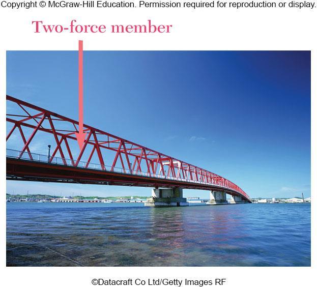
4 Introduction or the equilibrium of structures made of several connected parts, the internal forces as well the external forces are considered. In the interaction between connected parts, Newton s 3 rd Law states that the forces of action and reaction between bodies in contact have the same magnitude, same line of action, and opposite sense. Three categories of engineering structures are considered: a) Trusses: formed from two-force members, i.e., straight members with end point connections and forces that act only at these end points. b) rames: contain at least one multi-force member, i.e., member acted upon by 3 or more forces. c) Machines: structures containing moving parts designed to transmit and modify forces. 6-4

5 Definition of a Truss A truss consists of straight members connected at joints. No member is continuous through a joint. Most structures are made of several trusses joined together to form a space framework. Each truss carries those loads which act in its plane and may be treated as a two-dimensional structure. Bolted or welded connections are assumed to be pinned together. orces acting at the member ends reduce to a single force and no couple. Only twoforce members are considered. When forces tend to pull the member apart, it is in tension. When the forces tend to compress the member, it is in compression. 6-5

6 Definition of a Truss Members of a truss are slender and not capable of supporting large lateral loads. Loads must be applied at the joints. 6-6
7 Definition of a Truss 6-7
8 Simple Trusses A rigid truss will not collapse under the application of a load. A simple truss is constructed by successively adding two members and one connection to the basic triangular truss. 6-8
9 Method of Joints Dismember the truss and create a freebody diagram for each member and pin. Cons for equilibrium for the entire truss can be used to solve for 3 support reactions. The two forces exerted on each member are equal, have the same line of action, and opposite sense. orces exerted by a member on the pins or joints at its ends are directed along the member and equal and opposite. Cons of equilibrium are used to solve for 2 unknown forces at each pin (or joint), giving a total of 2n solutions, where n=number of joints. orces are found by solving for unknown forces while moving from joint to joint sequentially. 6-9


10 Joints Under Special Loading Cons orces in opposite members intersecting in two straight lines at a joint are equal. The forces in two opposite members are equal when a load is aligned with a third member. The third member force is equal to the load (including zero load). The forces in two members connected at a joint are equal if the members are aligned and zero otherwise. Recognition of joints under special loading cons simplifies a truss analysis. 6-10


11 Space Trusses An elementary space truss consists of 6 members connected at 4 joints to form a tetrahedron. A simple space truss is formed and can be extended when 3 new members and 1 joint are added at the same time. In a simple space truss, m = 3n - 6 where m is the number of members and n is the number of joints. Cons of equilibrium for the joints provide 3n equations. or a simple truss, 3n = m + 6 and the equations can be solved for m member forces and 6 support reactions. Equilibrium for the entire truss provides 6 adal equations which are not independent of the joint equations. 6-11
 and solve for the 3 support reactions Using the method of joints, determine the force in each member of the truss.")
12 Sample Problem 6.1 STRATEGY: What s the first step to solving this problem? Think, then discuss this with a neighbor. DRAW THE REE BODY DIAGRAM OR THE ENTIRE TRUSS (always first) and solve for the 3 support reactions Using the method of joints, determine the force in each member of the truss. Draw this BD and compare your sketch with a neighbor. Discuss with each other any differences. 6-12
13 Sample Problem 6.1 MODELING and ANALYSIS: Based on a free body diagram of the entire truss, solve the 3 equilibrium equations for the reactions at E and C. Looking at the BD, which sum of moments equation could you apply in order to find one of the unknown reactions with just this one equation? M C 0 E 2000 lb24 ft 1000 lb12 ft 6 ft E 10,000 lb Next, apply the remaining equilibrium cons to find the remaining 2 support reactions. 0 C 0 x y x C x lb lb 10,000 lb C C y y 7000lb 6-13

14 Sample Problem 6.1 We now solve the problem by moving sequentially from joint to joint and solving the associated BD for the unknown forces. Which joint should you start with, and why? Think, then discuss with a neighbor. Joints A or C are equally good because each has only 2 unknown forces. Use joint A and draw its BD and find the unknown forces. 2000lb AB AD Which joint should you move to next, and why? Discuss. AB AD 1500 lb 2500 lb Joint D, since it has 2 unknowns remaining (joint B has 3). Draw the BD and solve. T C DB DA DE DA DB DE 2500lb 3000lb T C 6-14
.")
15 Sample Problem 6.1 There are now only two unknown member forces at joint B. Assume both are in tension. y BE lb BE BE 3750lb C x BC 0 BC 5250 lb BC lb T There is one remaining unknown member force at joint E (or C). Use joint E and assume the member is in tension. x EC EC 8750 lb EC 8750lb C 6-15

16 Sample Problem 6.1 RELECT and THINK: Using the computed values of CB and CE, you can determine the reactions C x and C y by considering the equilibrium of Joint C (ig. 6). Since these reactions have already been determined from the equilibrium of the entire truss, this provides two checks of your computations. You can also simply use the computed values of all forces acting on the joint (forces in members and reactions) and check that the joint is in equilibrium. x y checks checks 6-16
17 Method of Sections When the force in only one member or the forces in a very few members are desired, the method of sections works well. To determine the force in member BD, form a section by cutting the truss at n-n and create a free body diagram for the left side. An BD could have been created for the right side, but why is this a less desirable choice? Think and discuss. Notice that the exposed internal forces are all assumed to be in tension. With only three members cut by the section, the equations for static equilibrium may be applied to determine the unknown member forces, including BD. 6-17
18 Method of Sections Using the left-side BD, write one equilibrium equation that can be solved to find BD. Check your equation with a neighbor; resolve any differences between your answers if you can. p k p Assume that the initial section cut was made using line k-k. Why would this be a poor choice? Think, then discuss with a neighbor. Notice that any cut may be chosen, so long as the cut creates a separated section. k So, for example, this cut with line p-p is acceptable. 6-18

19 Trusses Made of Several Simple Trusses Compound trusses are statically determinant, rigid, and completely constrained. m 2n 3 Truss contains a redundant member and is statically indeterminate. m 2n 3 Adal reaction forces may be necessary for a rigid truss. non-rigid m 2n 3 rigid m 2n 4 Necessary but insufficient con for a compound truss to be statically determinant, rigid, and completely constrained, m r 2n 6-19
20 Sample Problem 6.3 STRATEGY: List the steps for solving this problem. Discuss your list with a neighbor. 1. Draw the BD for the entire truss. Apply the equilibrium cons and solve for the reactions at A and L. Determine the force in members H, GH, and GI. 2. Make a cut through members H, GH, and GI and take the right-hand section as a free body (the left side would also be good). 3. Apply the cons for static equilibrium to determine the desired member forces. 6-20

21 Sample Problem 6.3 MODELING and ANALYSIS: A x Take the entire truss as a free body. Apply the cons for static equilibrium to solve for the reactions at A and L. A y M A 0 5 m 6 kn 10 m 6 kn 15 m 6 kn L 7.5 kn y 20 m1 kn 25 m1 kn 25 ml 0 20 kn L A y A y 12.5 kn x 0 A x L 6-21


22 Sample Problem 6.3 Make a cut through members H, GH, and GI and take the right-hand section as a free body. Draw this BD. What is the one equilibrium equation that could be solved to find GI? Confirm your answer with a neighbor. Sum of the moments about point H: M H kn10 m 1 kn GI kn 5 m GI 5.33 m 0 GI kn T 6-22


23 Sample Problem 6.3 H is shown as its components. What one equilibrium equation will determine H? tan G GL 8 m m M G 0 10 m 1 kn 7.5 kn15 m 1 kn H cos 8 m 0 H kn 5 m H kn C There are many options for finding GH at this point (e.g., S x =0, S y =0). Here is one more: tan GI HI M L 0 5 m 2 8 m 3 1 kn10 m 1 kn GH kn m GH cos10 m 0 GH 1.371kN C 6-23
24 Sample Problem 6.3 RELECT and THINK: Sometimes you should resolve a force into components to include it in the equilibrium equations. By first sliding this force along its line of action to a more strategic point, you might eliminate one of its components from a moment equilibrium equation. 2-24


25 Analysis of a rame rames and machines are structures with at least one multiforce (>2 forces) member. rames are designed to support loads and are usually stationary. Machines contain moving parts and transmit and modify forces. A free body diagram of the complete frame is used to determine the external forces acting on the frame. Internal forces are determined by dismembering the frame and creating free-body diagrams for each component. orces on two force members have known lines of action but unknown magnitude and sense. orces on multiforce members have unknown magnitude and line of action. They must be represented with two unknown components. orces between connected components are equal, have the same line of action, and opposite sense. 6-25
.")
26 rames That Collapse Without Supports Some frames may collapse if removed from their supports. Such frames can not be treated as rigid bodies. A free-body diagram of the complete frame indicates four unknown force components which cannot be determined from the three equilibrium cons (statically indeterminate). The frame must be considered as two distinct, but related, rigid bodies. With equal and opposite reactions at the contact point between members, the two free-body diagrams show 6 unknown force components. Equilibrium requirements for the two rigid bodies yield 6 independent equations. Thus, taking the frame apart made the problem solvable. 6-26
27 Sample Problem 6.4 STRATEGY: ollow the general procedure discussed in this section. irst treat the entire frame as a free body, which will enable you to find the reactions at A and B. Then dismember the frame and treat each member as a free body, which will give you the equations needed to find the force at C. Members ACE and BCD are connected by a pin at C and by the link DE. or the loading shown, determine the force in link DE and the components of the force exerted at C on member BCD. 6-27
28 Sample Problem 6.4 MODELING and ANALYSIS: Create a free-body diagram for the complete frame and solve for the support reactions. y 0 A y 480 N A y 480 N M A Note: N100 mm B160 mm x 0 B A x B 300 N A x 300 N A x 300 N 1 tan
29 Sample Problem 6.4 Create a free body diagram for member BCD (since the problem asked for forces on this body). Choose the best BD, then discuss your choice with a neighbor. Justify your choice. DE,x DE,y DE DE,x DE DE,y 6-29

30 Sample Problem 6.4 Using the best BD for member BCD, what is the one equilibrium equation that can directly find DE? Please discuss. M C DE 0 561N sin 250 mm 300 N60 mm 480 N100 mm DE 1 tan DE 561N C Sum of forces in the x and y directions may be used to find the force components at C. x 0 0 C C x x DE cos 300 N 561Ncos 300 N C x 795 N y 0 0 C C y y DE sin 480 N 561Nsin 480 N C y 216 N 6-30
31 Sample Problem 6.4 RELECT and THINK: Check the computations by considering the free body ACE. M A DE cos 300 mm DE sin 100 mm Cx 220 mm 561cos 300 mm 561sin 100 mm mm 0 (checks) 6-31

32 Machines Machines are structures designed to transmit and modify forces. Typically they transform input forces (P) into output forces (Q). Given the magnitude of P, determine the magnitude of Q. Create a free-body diagram of the complete machine, including the reaction that the wire exerts. The machine is a nonrigid structure. Use one of the components as a free-body. Discuss why the forces at A are such. Sum moments about A, 0 ap bq M A Q a b P 6-32
STATICS. Vector Mechanics for Engineers: Statics VECTOR MECHANICS FOR ENGINEERS: Contents 9/3/2015
 6 Analsis CHAPTER VECTOR MECHANICS OR ENGINEERS: STATICS erdinand P. Beer E. Russell Johnston, Jr. of Structures Lecture Notes: J. Walt Oler Texas Tech Universit Contents Introduction Definition of a Truss
CHAPTER 5 ANALYSIS OF STRUCTURES. Expected Outcome:
 CHAPTER ANALYSIS O STRUCTURES Expected Outcome: Able to analyze the equilibrium of structures made of several connected parts, using the concept of the equilibrium of a particle or of a rigid body, in
ENT 151 STATICS. Contents. Introduction. Definition of a Truss
 CHAPTER 6 Analysis ENT 151 STATICS Lecture Notes: Mohd Shukry Abdul Majid KUKUM of Structures Contents Introduction Definition of a Truss Simple Trusses Analysis of Trusses by the Method of Joints Joints
MEE224: Engineering Mechanics Lecture 4
 Lecture 4: Structural Analysis Part 1: Trusses So far we have only analysed forces and moments on a single rigid body, i.e. bars. Remember that a structure is a formed by and this lecture will investigate
Outline: Frames Machines Trusses
 Outline: Frames Machines Trusses Properties and Types Zero Force Members Method of Joints Method of Sections Space Trusses 1 structures are made up of several connected parts we consider forces holding
Chapter 6: Structural Analysis
 Chapter 6: Structural Analysis Chapter Objectives To show how to determine the forces in the members of a truss using the method of joints and the method of sections. To analyze the forces acting on the
Lecture 23. ENGR-1100 Introduction to Engineering Analysis FRAMES S 1
 ENGR-1100 Introduction to Engineering Analysis Lecture 23 Today s Objectives: Students will be able to: a) Draw the free body diagram of a frame and its members. FRAMES b) Determine the forces acting at
Announcements. Trusses Method of Joints
 Announcements Mountain Dew is an herbal supplement Today s Objectives Define a simple truss Trusses Method of Joints Determine the forces in members of a simple truss Identify zero-force members Class
Equilibrium Equilibrium and Trusses Trusses
 Equilibrium and Trusses ENGR 221 February 17, 2003 Lecture Goals 6-4 Equilibrium in Three Dimensions 7-1 Introduction to Trusses 7-2Plane Trusses 7-3 Space Trusses 7-4 Frames and Machines Equilibrium Problem
ENGR-1100 Introduction to Engineering Analysis. Lecture 23
 ENGR-1100 Introduction to Engineering Analysis Lecture 23 Today s Objectives: Students will be able to: a) Draw the free body diagram of a frame and its members. FRAMES b) Determine the forces acting at
6.6 FRAMES AND MACHINES APPLICATIONS. Frames are commonly used to support various external loads.
 6.6 FRAMES AND MACHINES APPLICATIONS Frames are commonly used to support various external loads. How is a frame different than a truss? How can you determine the forces at the joints and supports of a
Chapter 6: Structural Analysis
 Chapter 6: Structural Analysis APPLICATIONS Trusses are commonly used to support a roof. For a given truss geometry and load, how can we determine the forces in the truss members and select their sizes?
SRSD 2093: Engineering Mechanics 2SRRI SECTION 19 ROOM 7, LEVEL 14, MENARA RAZAK
 SRSD 2093: Engineering Mechanics 2SRRI SECTION 19 ROOM 7, LEVEL 14, MENARA RAZAK SIMPLE TRUSSES, THE METHOD OF JOINTS, & ZERO-FORCE MEMBERS Today s Objectives: Students will be able to: a) Define a simple
FRAMES AND MACHINES Learning Objectives 1). To evaluate the unknown reactions at the supports and the interaction forces at the connection points of a
. To evaluate the unknown reactions at the supports and the interaction forces at the connection points of a") FRAMES AND MACHINES Learning Objectives 1). To evaluate the unknown reactions at the supports and the interaction forces at the connection points of a rigid frame in equilibrium by solving the equations
FRAMES AND MACHINES Learning Objectives 1). To evaluate the unknown reactions at the supports and the interaction forces at the connection points of a rigid frame in equilibrium by solving the equations
ENGR-1100 Introduction to Engineering Analysis. Lecture 19
 ENGR-1100 Introduction to Engineering Analysis Lecture 19 SIMPLE TRUSSES, THE METHOD OF JOINTS, & ZERO-FORCE MEMBERS Today s Objectives: Students will be able to: In-Class Activities: a) Define a simple
READING QUIZ. 2. When using the method of joints, typically equations of equilibrium are applied at every joint. A) Two B) Three C) Four D) Six
 Two B) Three C) Four D) Six") READING QUIZ 1. One of the assumptions used when analyzing a simple truss is that the members are joined together by. A) Welding B) Bolting C) Riveting D) Smooth pins E) Super glue 2. When using the method
READING QUIZ 1. One of the assumptions used when analyzing a simple truss is that the members are joined together by. A) Welding B) Bolting C) Riveting D) Smooth pins E) Super glue 2. When using the method
Plane Trusses Trusses
 TRUSSES Plane Trusses Trusses- It is a system of uniform bars or members (of various circular section, angle section, channel section etc.) joined together at their ends by riveting or welding and constructed
Engineering Mechanics: Statics STRUCTURAL ANALYSIS. by Dr. Ibrahim A. Assakkaf SPRING 2007 ENES 110 Statics
 CHAPTER Engineering Mechanics: Statics STRUCTURAL ANALYSIS College of Engineering Department of Mechanical Engineering Tenth Edition 6a by Dr. Ibrahim A. Assakkaf SPRING 2007 ENES 110 Statics Department
ME Statics. Structures. Chapter 4
 ME 108 - Statics Structures Chapter 4 Outline Applications Simple truss Method of joints Method of section Germany Tacoma Narrows Bridge http://video.google.com/videoplay?docid=-323172185412005564&q=bruce+lee&pl=true
The analysis of trusses Mehrdad Negahban (1999)
") The analysis of trusses Mehrdad Negahban (1999) A truss: A truss is a structure made of two force members all pin connected to each other. The method of joints: This method uses the free-body-diagram of
The analysis of trusses Mehrdad Negahban (1999) A truss: A truss is a structure made of two force members all pin connected to each other. The method of joints: This method uses the free-body-diagram of
Newton s Third Law Newton s Third Law: For each action there is an action and opposite reaction F
 FRAMES AND MACHINES Learning Objectives 1). To evaluate the unknown reactions at the supports and the interaction forces at the connection points of a rigid frame in equilibrium by solving the equations
STATICS. Bodies VECTOR MECHANICS FOR ENGINEERS: Ninth Edition CHAPTER. Ferdinand P. Beer E. Russell Johnston, Jr.
 N E 4 Equilibrium CHAPTER VECTOR MECHANICS FOR ENGINEERS: STATICS Ferdinand P. Beer E. Russell Johnston, Jr. Lecture Notes: J. Walt Oler Texas Tech University of Rigid Bodies 2010 The McGraw-Hill Companies,
Method of Sections for Truss Analysis
 Method of Sections for Truss Analysis Notation: (C) = shorthand for compression P = name for load or axial force vector (T) = shorthand for tension Joint Configurations (special cases to recognize for
To show how to determine the forces in the members of a truss using the method of joints and the method of sections.
 5 Chapter Objectives To show how to determine the forces in the members of a truss using the method of joints and the method of sections. To analyze the forces acting on the members of frames and machines
SIMPLE TRUSSES, THE METHOD OF JOINTS, & ZERO-FORCE MEMBERS
 SIMPLE TRUSSES, THE METHOD OF JOINTS, & ZERO-FORCE MEMBERS Today s Objectives: Students will be able to: a) Define a simple truss. b) Determine the forces in members of a simple truss. c) Identify zero-force
7 STATICALLY DETERMINATE PLANE TRUSSES
 7 STATICALLY DETERMINATE PLANE TRUSSES OBJECTIVES: This chapter starts with the definition of a truss and briefly explains various types of plane truss. The determinancy and stability of a truss also will
Pin-Jointed Frame Structures (Frameworks)
") Pin-Jointed rame Structures (rameworks) 1 Pin Jointed rame Structures (rameworks) A pin-jointed frame is a structure constructed from a number of straight members connected together at their ends by frictionless
Pin-Jointed rame Structures (rameworks) 1 Pin Jointed rame Structures (rameworks) A pin-jointed frame is a structure constructed from a number of straight members connected together at their ends by frictionless
Statics: Lecture Notes for Sections
 Chapter 6: Structural Analysis Today s Objectives: Students will be able to: a) Define a simple truss. b) Determine the forces in members of a simple truss. c) Identify zero-force members. READING QUIZ
Equilibrium. Rigid Bodies VECTOR MECHANICS FOR ENGINEERS: STATICS. Eighth Edition CHAPTER. Ferdinand P. Beer E. Russell Johnston, Jr.
 Eighth E 4 Equilibrium CHAPTER VECTOR MECHANICS FOR ENGINEERS: STATICS Ferdinand P. Beer E. Russell Johnston, Jr. Lecture Notes: J. Walt Oler Texas Tech University of Rigid Bodies Contents Introduction
CHAPTER 2: EQUILIBRIUM OF RIGID BODIES
 For a rigid body to be in equilibrium, the net force as well as the net moment about any arbitrary point O must be zero Summation of all external forces. Equilibrium: Sum of moments of all external forces.
Static Equilibrium. University of Arizona J. H. Burge
 Static Equilibrium Static Equilibrium Definition: When forces acting on an object which is at rest are balanced, then the object is in a state of static equilibrium. - No translations - No rotations In
Calculating Truss Forces. Method of Joints
 Calculating Truss Forces Method of Joints Forces Compression body being squeezed Tension body being stretched Truss truss is composed of slender members joined together at their end points. They are usually
Tenth Edition STATICS 1 Ferdinand P. Beer E. Russell Johnston, Jr. David F. Mazurek Lecture Notes: John Chen California Polytechnic State University
 T E CHAPTER 1 VECTOR MECHANICS FOR ENGINEERS: STATICS Ferdinand P. Beer E. Russell Johnston, Jr. David F. Mazurek Lecture Notes: Introduction John Chen California Polytechnic State University! Contents
CHAPTER 5 Statically Determinate Plane Trusses
 CHAPTER 5 Statically Determinate Plane Trusses TYPES OF ROOF TRUSS TYPES OF ROOF TRUSS ROOF TRUSS SETUP ROOF TRUSS SETUP OBJECTIVES To determine the STABILITY and DETERMINACY of plane trusses To analyse
CHAPTER 5 Statically Determinate Plane Trusses TYPES OF ROOF TRUSS
 CHAPTER 5 Statically Determinate Plane Trusses TYPES OF ROOF TRUSS 1 TYPES OF ROOF TRUSS ROOF TRUSS SETUP 2 ROOF TRUSS SETUP OBJECTIVES To determine the STABILITY and DETERMINACY of plane trusses To analyse
STATICS. Bodies. Vector Mechanics for Engineers: Statics VECTOR MECHANICS FOR ENGINEERS: Design of a support
 4 Equilibrium CHAPTER VECTOR MECHANICS FOR ENGINEERS: STATICS Ferdinand P. Beer E. Russell Johnston, Jr. Lecture Notes: J. Walt Oler Texas Tech University of Rigid Bodies 2010 The McGraw-Hill Companies,
The centroid of an area is defined as the point at which (12-2) The distance from the centroid of a given area to a specified axis may be found by
 The distance from the centroid of a given area to a specified axis may be found by") Unit 12 Centroids Page 12-1 The centroid of an area is defined as the point at which (12-2) The distance from the centroid of a given area to a specified axis may be found by (12-5) For the area shown
Unit 12 Centroids Page 12-1 The centroid of an area is defined as the point at which (12-2) The distance from the centroid of a given area to a specified axis may be found by (12-5) For the area shown
ME 201 Engineering Mechanics: Statics. Final Exam Review
 ME 201 Engineering Mechanics: Statics inal Exam Review inal Exam Testing Center (Proctored, 1 attempt) Opens: Monday, April 9 th Closes : riday, April 13 th Test ormat 15 Problems 10 Multiple Choice (75%)
Similar to trusses, frames are generally fixed, load carrying structures.
 Similar to trusses, frames are generally fixed, load carrying structures. The main difference between a frame and a truss is that in a frame at least one member is a multi force member (çoklu kuvvet elemanı).
EQUATIONS OF EQUILIBRIUM & TWO- AND THREE-FORCE MEMEBERS
 EQUATIONS OF EQUILIBRIUM & TWO- AND THREE-FORCE MEMEBERS Today s Objectives: Students will be able to: a) Apply equations of equilibrium to solve for unknowns, and, b) Recognize two-force members. In-Class
ENGINEERING MECHANICS STATIC
 Trusses Simple trusses The basic element of a truss is the triangle, three bars joined by pins at their ends, fig. a below, constitutes a rigid frame. The term rigid is used to mean noncollapsible and
STATICALLY INDETERMINATE STRUCTURES
 STATICALLY INDETERMINATE STRUCTURES INTRODUCTION Generally the trusses are supported on (i) a hinged support and (ii) a roller support. The reaction components of a hinged support are two (in horizontal
MECHANICS OF MATERIALS
 Third E CHAPTER 1 Introduction MECHANICS OF MATERIALS Ferdinand P. Beer E. Russell Johnston, Jr. John T. DeWolf Lecture Notes: J. Walt Oler Texas Tech University Concept of Stress Contents Concept of Stress
EQUATIONS OF EQUILIBRIUM & TWO-AND THREE-FORCE MEMEBERS
 EQUATIONS OF EQUILIBRIUM & TWO-AND THREE-FORCE MEMEBERS Today s Objectives: Students will be able to: a) Apply equations of equilibrium to solve for unknowns, and, b) Recognize two-force members. READING
3.1 CONDITIONS FOR RIGID-BODY EQUILIBRIUM
 3.1 CONDITIONS FOR RIGID-BODY EQUILIBRIUM Consider rigid body fixed in the x, y and z reference and is either at rest or moves with reference at constant velocity Two types of forces that act on it, the
Calculating Truss Forces Unit 2 Lesson 2.1 Statics
 alculating Truss Forces alculating Truss Forces Principles of Engineering 22 Forces ompression body being squeezed Tension body being stretched Truss truss is composed of slender members joined together
ME 201 Engineering Mechanics: Statics
 ME 201 Engineering Mechanics: Statics Unit 7.1 Simple Trusses Method of Joints Zero Force Members Simple Truss structure composed of slender members joined together at their end points Planar Truss Simple
Vector Mechanics: Statics
 PDHOnline Course G492 (4 PDH) Vector Mechanics: Statics Mark A. Strain, P.E. 2014 PDH Online PDH Center 5272 Meadow Estates Drive Fairfax, VA 22030-6658 Phone & Fax: 703-988-0088 www.pdhonline.org www.pdhcenter.com
Mechanics of Materials
 Mechanics of Materials 2. Introduction Dr. Rami Zakaria References: 1. Engineering Mechanics: Statics, R.C. Hibbeler, 12 th ed, Pearson 2. Mechanics of Materials: R.C. Hibbeler, 9 th ed, Pearson 3. Mechanics
Engineering Mechanics Department of Mechanical Engineering Dr. G. Saravana Kumar Indian Institute of Technology, Guwahati
 Engineering Mechanics Department of Mechanical Engineering Dr. G. Saravana Kumar Indian Institute of Technology, Guwahati Module 3 Lecture 6 Internal Forces Today, we will see analysis of structures part
EQUATIONS OF EQUILIBRIUM & TWO- AND THREE-FORCE MEMBERS
 EQUATIONS OF EQUILIBRIUM & TWO- AND THREE-FORCE MEMBERS Today s Objectives: Students will be able to: a) Apply equations of equilibrium to solve for unknowns, and, b) Recognize two-force members. APPLICATIONS
Statics and Mechanics of Materials
 Second E 1 Introduction CHAPTER Ferdinand P. Beer E. Russell Johnston, Jr. John T. DeWolf David F. Mazurek Contents What is Mechanics? Systems of Units Method of Solving Problems Numerical Accuracy 1-2
Method of Sections for Truss Analysis
 RH 331 Note Set 5.2 F2013abn Method of Sections for Truss nalysis Notation: () = shorthand for compression = name for load or axial force vector (T) = shorthand for tension Joint onfigurations (special
Equilibrium of Rigid Bodies
 Equilibrium of Rigid Bodies 1 2 Contents Introduction Free-Bod Diagram Reactions at Supports and Connections for a wo-dimensional Structure Equilibrium of a Rigid Bod in wo Dimensions Staticall Indeterminate
Chapter 3 Trusses. Member CO Free-Body Diagram. The force in CO can be obtained by using section bb. Equations of Equilibrium.
 Chapter 3 Trusses Procedure for analysis 1 Free body diagram: make a decision as to how to cut or section the truss through the members where forces are to be determined. 2 Equation of equilibrium: apply
Lecture 17 February 23, 2018
 Statics - TAM 20 & TAM 2 Lecture 7 ebruary 23, 208 Announcements Monday s lecture: watch for Piazza announcement over weekend for possible change Concept Inventory: Ungraded assessment of course knowledge
three Equilibrium 1 and planar trusses ELEMENTS OF ARCHITECTURAL STRUCTURES: FORM, BEHAVIOR, AND DESIGN DR. ANNE NICHOLS SPRING 2015 lecture ARCH 614
 ELEMENTS OF ARCHITECTURAL STRUCTURES: FORM, BEHAVIOR, AND DESIGN DR. ANNE NICHOLS SPRING 2015 lecture three equilibrium and planar trusses Equilibrium 1 Equilibrium balanced steady resultant of forces
1. Determine the Zero-Force Members in the plane truss.
 1. Determine the Zero-orce Members in the plane truss. 1 . Determine the force in each member of the loaded truss. Use the Method of Joints. 3. Determine the force in member GM by the Method of Section.
three Point Equilibrium 1 and planar trusses ARCHITECTURAL STRUCTURES: FORM, BEHAVIOR, AND DESIGN DR. ANNE NICHOLS SUMMER 2014 lecture
 ARCHITECTURAL STRUCTURES: FORM, BEHAVIOR, AND DESIGN DR. ANNE NICHOLS SUMMER 2014 lecture three point equilibrium http:// nisee.berkeley.edu/godden and planar trusses Point Equilibrium 1 Equilibrium balanced
Engineering Mechanics: Statics in SI Units, 12e
 Engineering Mechanics: Statics in SI Units, 12e 5 Equilibrium of a Rigid Body Chapter Objectives Develop the equations of equilibrium for a rigid body Concept of the free-body diagram for a rigid body
Similar to trusses, frames are generally fixed, load carrying structures.
 Similar to trusses, frames are generally fixed, load carrying structures. The main difference between a frame and a truss is that in a frame at least one member is a multi force member (çoklu kuvvet elemanı).
Announcements. Equilibrium of a Rigid Body
 Announcements Equilibrium of a Rigid Body Today s Objectives Identify support reactions Draw a free body diagram Class Activities Applications Support reactions Free body diagrams Examples Engr221 Chapter
EQUATIONS OF EQUILIBRIUM & TWO- AND THREE-FORCE MEMBERS
 EQUATIONS OF EQUILIBRIUM & TWO- AND THREE-FORCE MEMBERS Today s Objectives: Students will be able to: a) Apply equations of equilibrium to solve for unknowns b) Identify support reactions c) Recognize
MECHANICS OF MATERIALS
 Fifth SI Edition CHTER 1 MECHNICS OF MTERILS Ferdinand. Beer E. Russell Johnston, Jr. John T. DeWolf David F. Mazurek Introduction Concept of Stress Lecture Notes: J. Walt Oler Teas Tech University Contents
1. Determine the Zero-Force Members in the plane truss.
 1. Determine the Zero-orce Members in the plane truss. 1 . Determine the forces in members G, CG, BC, and E for the loaded crane truss. Use the Method of Joints. 3. Determine the forces in members CG and
REVIEW. Final Exam. Final Exam Information. Final Exam Information. Strategy for Studying. Test taking strategy. Sign Convention Rules
 Final Exam Information REVIEW Final Exam (Print notes) DATE: WEDNESDAY, MAY 12 TIME: 1:30 PM - 3:30 PM ROOM ASSIGNMENT: Toomey Hall Room 199 1 2 Final Exam Information Comprehensive exam covers all topics
EQUATIONS OF EQUILIBRIUM & TWO- AND THREE-FORCE MEMEBERS
 EQUATIONS OF EQUILIBRIUM & TWO- AND THREE-FORCE MEMEBERS Today s Objectives: Students will be able to: a) Apply equations of equilibrium to solve for unknowns, and b) Recognize two-force members. In-Class
 Name ME 270 Summer 2006 Examination No. 1 PROBLEM NO. 3 Given: Below is a Warren Bridge Truss. The total vertical height of the bridge is 10 feet and each triangle has a base of length, L = 8ft. Find:
Figure 9.1 (a) Six performers in the circus; (b) free-body diagram of the performers / Alan Thornton/Stone/Getty Images
 Six performers in the circus; (b) free-body diagram of the performers / Alan Thornton/Stone/Getty Images") Creatas In this chapter we use equilibrium analysis to look at loads internal to three types of systems: frames, machines, and trusses. By the end of this chapter, you will be able to systematically find
Creatas In this chapter we use equilibrium analysis to look at loads internal to three types of systems: frames, machines, and trusses. By the end of this chapter, you will be able to systematically find
Lecture 20. ENGR-1100 Introduction to Engineering Analysis THE METHOD OF SECTIONS
 ENGR-1100 Introduction to Engineering Analysis Lecture 20 THE METHOD OF SECTIONS Today s Objectives: Students will be able to determine: 1. Forces in truss members using the method of sections. In-Class
ENGR-1100 Introduction to Engineering Analysis. Lecture 20
 ENGR-1100 Introduction to Engineering Analysis Lecture 20 Today s Objectives: THE METHOD OF SECTIONS Students will be able to determine: 1. Forces in truss members using the method of sections. In-Class
MT225 Homework 6 - Solution. Problem 1: [34] 5 ft 5 ft 5 ft A B C D. 12 kips. 10ft E F G
![MT225 Homework 6 - Solution. Problem 1: [34] 5 ft 5 ft 5 ft A B C D. 12 kips. 10ft E F G](/thumbs/73/69403767.jpg "MT225 Homework 6 - Solution. Problem 1: [34] 5 ft 5 ft 5 ft A B C D. 12 kips. 10ft E F G") MT225 Homework 6 - Solution Problem 1: [34] 5 ft 5 ft 5 ft C D 10ft 12 kips E G To begin, we need to find the reaction forces at supports and E. To do so, we draw a free-body diagram of the entire structure
MT225 Homework 6 - Solution Problem 1: [34] 5 ft 5 ft 5 ft C D 10ft 12 kips E G To begin, we need to find the reaction forces at supports and E. To do so, we draw a free-body diagram of the entire structure
Lecture 17 February 23, 2018
 Statics - TAM 20 & TAM 2 Lecture 7 ebruary 23, 208 Announcements Monday s lecture: watch for Piazza announcement over weekend for possible change Concept Inventory: Ungraded assessment of course knowledge
Chapter Objectives. Copyright 2011 Pearson Education South Asia Pte Ltd
 Chapter Objectives To develop the equations of equilibrium for a rigid body. To introduce the concept of the free-body diagram for a rigid body. To show how to solve rigid-body equilibrium problems using
MECHANICS OF MATERIALS
 STATICS AND MECHANICS OF MATERIALS Ferdinand P. Beer E. Russell Johnston, Jr, John T. DeWolf David E Mazurek \Cawect Mc / iur/» Craw SugomcT Hilt Introduction 1 1.1 What is Mechanics? 2 1.2 Fundamental
Please review the following statement: I certify that I have not given unauthorized aid nor have I received aid in the completion of this exam.
 Please review the following statement: I certify that I have not given unauthorized aid nor have I received aid in the completion of this exam. Signature: INSTRUCTIONS Begin each problem in the space provided
Eng Sample Test 4
 1. An adjustable tow bar connecting the tractor unit H with the landing gear J of a large aircraft is shown in the figure. Adjusting the height of the hook F at the end of the tow bar is accomplished by
Module 3. Analysis of Statically Indeterminate Structures by the Displacement Method
 odule 3 Analysis of Statically Indeterminate Structures by the Displacement ethod Lesson 16 The Slope-Deflection ethod: rames Without Sidesway Instructional Objectives After reading this chapter the student
STATICS. Statics of Particles VECTOR MECHANICS FOR ENGINEERS: Eighth Edition CHAPTER. Ferdinand P. Beer E. Russell Johnston, Jr.
 Eighth E CHAPTER VECTOR MECHANICS FOR ENGINEERS: STATICS Ferdinand P. Beer E. Russell Johnston, Jr. Statics of Particles Lecture Notes: J. Walt Oler Teas Tech Universit Contents Introduction Resultant
Lecture 8: Flexibility Method. Example
 ecture 8: lexibility Method Example The plane frame shown at the left has fixed supports at A and C. The frame is acted upon by the vertical load P as shown. In the analysis account for both flexural and
Equilibrium of rigid bodies Mehrdad Negahban (1999)
") Equilibrium of rigid bodies Mehrdad Negahban (1999) Static equilibrium for a rigid body: A body (or any part of it) which is currently stationary will remain stationary if the resultant force and resultant
Equilibrium of rigid bodies Mehrdad Negahban (1999) Static equilibrium for a rigid body: A body (or any part of it) which is currently stationary will remain stationary if the resultant force and resultant
ENGR-1100 Introduction to Engineering Analysis. Lecture 13
 ENGR-1100 Introduction to Engineering Analysis Lecture 13 EQUILIBRIUM OF A RIGID BODY & FREE-BODY DIAGRAMS Today s Objectives: Students will be able to: a) Identify support reactions, and, b) Draw a free-body
Equilibrium of a Particle
 ME 108 - Statics Equilibrium of a Particle Chapter 3 Applications For a spool of given weight, what are the forces in cables AB and AC? Applications For a given weight of the lights, what are the forces
Lecture 0. Statics. Module 1. Overview of Mechanics Analysis. IDeALab. Prof. Y.Y.KIM. Solid Mechanics
 Lecture 0. Statics Module 1. Overview of Mechanics Analysis Overview of Mechanics Analysis Procedure of Solving Mechanics Problems Objective : Estimate the force required in the flexor muscle Crandall,
In this chapter trusses, frames and machines will be examines as engineering structures.
 In the previous chapter we have employed the equations of equilibrium in order to determine the support / joint reactions acting on a single rigid body or a system of connected members treated as a single
Introduction. 1.1 Introduction. 1.2 Trigonometrical definitions
 Introduction 1.1 Introduction Stress analysis is an important part of engineering science, as failure of most engineering components is usually due to stress. The component under a stress investigation
If the solution does not follow a logical thought process, it will be assumed in error.
 Please review the following statement: I certify that I have not given unauthorized aid nor have I received aid in the completion of this exam. If I detect cheating I will write a note on my exam and raise
Statics Chapter II Fall 2018 Exercises Corresponding to Sections 2.1, 2.2, and 2.3
 Statics Chapter II Fall 2018 Exercises Corresponding to Sections 2.1, 2.2, and 2.3 2 3 Determine the magnitude of the resultant force FR = F1 + F2 and its direction, measured counterclockwise from the
Equilibrium of a Rigid Body. Chapter 5
 Equilibrium of a Rigid Body Chapter 5 Overview Rigid Body Equilibrium Free Body Diagrams Equations of Equilibrium 2 and 3-Force Members Statical Determinacy CONDITIONS FOR RIGID-BODY EQUILIBRIUM Recall
MECHANICS OF MATERIALS
 GE SI CHAPTER 3 MECHANICS OF MATERIALS Ferdinand P. Beer E. Russell Johnston, Jr. John T. DeWolf David F. Mazurek Torsion Lecture Notes: J. Walt Oler Texas Tech University Torsional Loads on Circular Shafts
FORCE ANALYSIS OF MACHINERY. School of Mechanical & Industrial Engineering, AAiT
 1 FORCE ANALYSIS OF MACHINERY School of Mechanical & Industrial Engineering, AAiT INTRODUCTION 2 A machine is a device that performs work and, as such, transmits energy by means mechanical force from a
Supplement: Statically Indeterminate Trusses and Frames
 : Statically Indeterminate Trusses and Frames Approximate Analysis - In this supplement, we consider an approximate method of solving statically indeterminate trusses and frames subjected to lateral loads
Name. ME 270 Fall 2005 Final Exam PROBLEM NO. 1. Given: A distributed load is applied to the top link which is, in turn, supported by link AC.
 Name ME 270 Fall 2005 Final Exam PROBLEM NO. 1 Given: A distributed load is applied to the top link which is, in turn, supported by link AC. Find: a) Draw a free body diagram of link BCDE and one of link
Truss Analysis Method of Joints. Steven Vukazich San Jose State University
 Truss nalysis Method of Joints Steven Vukazich San Jose State University General Procedure for the nalysis of Simple Trusses using the Method of Joints 1. raw a Free Body iagram (FB) of the entire truss
MECE 3321 MECHANICS OF SOLIDS CHAPTER 1
 MECE 3321 MECHANICS O SOLIDS CHAPTER 1 Samantha Ramirez, MSE WHAT IS MECHANICS O MATERIALS? Rigid Bodies Statics Dynamics Mechanics Deformable Bodies Solids/Mech. Of Materials luids 1 WHAT IS MECHANICS
Unit M1.4 (All About) Trusses
 Trusses") Unit M1.4 (ll bout) Trusses Readings: DL 1.9 16.001/002 -- Unified Engineering Department of eronautics and stronautics Massachusetts Institute of Technology LERNING OBJETIVES FOR UNIT M1.4 Through participation
Unit M1.4 (ll bout) Trusses Readings: DL 1.9 16.001/002 -- Unified Engineering Department of eronautics and stronautics Massachusetts Institute of Technology LERNING OBJETIVES FOR UNIT M1.4 Through participation
Spring 2018 Lecture 28 Exam Review
 Statics - TAM 210 & TAM 211 Spring 2018 Lecture 28 Exam Review Announcements Concept Inventory: Ungraded assessment of course knowledge Extra credit: Complete #1 or #2 for 0.5 out of 100 pt of final grade
Mechanical Design in Optical Engineering
 OPTI Buckling Buckling and Stability: As we learned in the previous lectures, structures may fail in a variety of ways, depending on the materials, load and support conditions. We had two primary concerns:
EQUILIBRIUM OF RIGID BODIES
 EQUILIBRIUM OF RIGID BODIES Equilibrium A body in equilibrium is at rest or can translate with constant velocity F = 0 M = 0 EQUILIBRIUM IN TWO DIMENSIONS Case where the force system acting on a rigid
and F NAME: ME rd Sample Final Exam PROBLEM 1 (25 points) Prob. 1 questions are all or nothing. PROBLEM 1A. (5 points)
 Prob. 1 questions are all or nothing. PROBLEM 1A. (5 points)") ME 270 3 rd Sample inal Exam PROBLEM 1 (25 points) Prob. 1 questions are all or nothing. PROBLEM 1A. (5 points) IND: In your own words, please state Newton s Laws: 1 st Law = 2 nd Law = 3 rd Law = PROBLEM
ME 270 3 rd Sample inal Exam PROBLEM 1 (25 points) Prob. 1 questions are all or nothing. PROBLEM 1A. (5 points) IND: In your own words, please state Newton s Laws: 1 st Law = 2 nd Law = 3 rd Law = PROBLEM