In this chapter trusses, frames and machines will be examines as engineering structures.
|
|
|
- Philip Hall
- 6 years ago
- Views:
Transcription
1
2 In the previous chapter we have employed the equations of equilibrium in order to determine the support / joint reactions acting on a single rigid body or a system of connected members treated as a single rigid body. Determination of the support / joint reactions constitutes only the first step of the analysis in engineering structures. From now on we will focus on the determination of the forces internal to a structure, that is, forces of action and reaction between the connected members. An engineering structure is any connected system of members built to support or transfer forces and to safely withstand the loads applied to it. To determine the forces internal to an engineering structure, we must dismember the structure and analyze separate free body diagrams of individual members or combination of members which are mostly connected each other using smooth pin connections. Determination of joint reactions is of great importance in the selection of connection members that hold the structure as a whole.
3 Joint reactions always occur in pairs that are equal in magnitude and opposite in direction. If not isolated from the rest of the structure or the environment by means of a free body diagram, joint forces are not included in the diagram since they will be internal forces. In order to determine the joint reactions, the structures must be separated into at least two or more parts. At these separation points the joint reactions become external forces and thus, are included in the equations of equilibrium. In this chapter trusses, frames and machines will be examines as engineering structures.
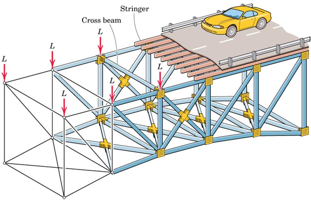
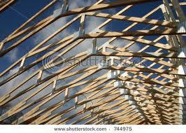
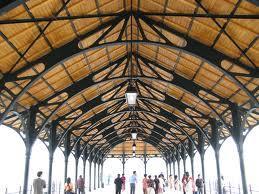
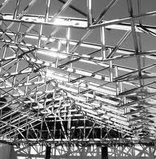
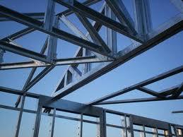
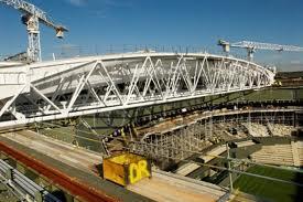
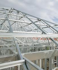
4 A framework composed of members joined at their ends to form a rigid structure is called a truss. Bridges, roof supports, derricks, grid line supports, motorway passages and other such structures are examples of trusses. Structural members commonly used are I-beams, channels, angles, bars and special shapes which are fastened together at their ends by welding, riveted connections, or large bolts or pins using large plates named as gusset plates. For bridges and similar structures, plane trusses are commonly utilized in pairs with one truss assembly placed on each side of the structure. The combined weight of the roadway and vehicles is transferred to either side.
5
6
7
8
9


10
 A Gusset")
) (Köşebent L")
11 I-Beam (I-Kiriş) Channel Beam (U-Profil) A Gusset Plate (Bayrak) Angled Beam Bar (Çubuk)) (Köşebent L profil)
12 The basic element of a plane truss is the triangle. Three bars joined by pins at their ends constitute a rigid frame. In planar trusses all bars and external forces acting on the system lie in a single plane. P A B C
13 A Typical Roof Truss Joint (Düğüm) A Support Reactions G B F Member (Çubuk) External Force E D C Support Reaction A truss can be extended by additing extra tirangles to the system. Such trusses comprising only of trianges are called simple trusses basit kafes. In a simple truss it is possible to check the rigidity of the truss and whether the joint forces can be determined or not by using the following equation: m : number of members j : number of joints m=2j-3 should be satisfied for rigidity
14 1. In a truss system it is assumed that all bars are two forces members. The weights of members are neglected compared to the forces they are supporting. Therefore members work either in tension or compression. (Çeki) (Bası)
15 2. When welded or riveted connections are used to join structural members, we may usually assume that the connection is a pin joint if the centerline of the members are concurrent at the joint. In this case the joint does not support any moment since it allows for the rotation of the members. 3. It is assumed in the analysis of simple trusses that all external forces are applied at the pin connections. 4. Since bars used in trusses are long, slender elements they can support very little transverse loads or bending moments.
16 Determinaton of Zero-Force Members (Boş Çubukların Belirlenmesi) Determination of the zero-force members beforehand will generally facilitate the solution of the problem 1.Rule: When two collinear members are under compression, it is necessary to add a third member to maintain alignment of the two members and prevent buckling. We see from a force summation in the y direction that the force F 3 in the third member must be zero and from the x direction that F 1 =F 2. This conclusion holds regardless of the angle q and holds also if the collinear members are in tension. If an external force in y direction were applied to the joint, then F 3 would no longer be zero.
17 2. Rule : When two noncollinear members are joined as shown, then in the absence of an externally load at this joint, the forces in both members must be zero, as we can see from the two force summations.
18 Determine the Zero-Force Members in the plane truss.
19 Equal Force Members (Eşit Yük Taşıyan Elemanlar) When two pairs of collinear members are joined as shown, the forces in each pair must be equal and opposite. F 1 and F 2, F 3 and F 4 collinear
20 1 This method for finding the forces in the members of a truss consists of satisfying the conditions of equilibrium for the forces acting on the connecting pin of each joint. The method therefore deals with the equilibrium of concurrent forces, and only two independent equilibrium equations are involved (SF x =0, SF y =0).
21 Sign convention (İşaret anlaşması): It is initially assumed that all the members work in tension. Therefore, when the FBDs of pins are being constructed, members are shown directed away from the joint. After employing the equations of equilibrium, if the result yields a positive value (+), it means that the member actually works in tension (T) (çeki), if the result yields a negative value (-), it means that the member works in compression (C) (bası).
22 1. Determine the force in each member of the loaded truss.
23 2) METHOD OF SECTIONS (Kesim Yöntemi) When analyzing plane trusses by the method of joints, we need only two of the three equilibrium equations because the procedures involve concurrent forces at each joint. We can take advantage of the third or moment equation of equilibrium by selecting an entire section of the truss for the free body in equilibrium under the action of nonconcurrent system of forces. The Method of Sections is often employed when forces in limited number of members are asked for and is based on the two dimensional equilibrium of rigid bodies (SF x =0, SF y =0, SM=0). This method has the basic advantage that the force in almost any desired member may be found directly from an analysis of a section which has cut that member. Thus, it is not necessary to proceed with the calculation from joint to joint until the member in question has been reached. In choosing a section of the truss, in general, not more than three members whose forces are unknown should be cut, since there are only three available independent equilibrium relations.
24 Once a truss is cut into two parts, one of the parts is taken into consideration and all the internal forces now become external from where the cut was passed. The forces are initially assumed as working in tension, so, they are shown directed away from the FBD. After employing the equations of equilibrium, if the result yields a positive value (+), it means that the member actually works in tension (T) (çeki), if the result yields a negative value (-), it means that the member works in compression (C) (bası). Before starting to solve with method, if necessary the support reactions can be determined from the FBD of the whole truss and also zero-force members can be identified. It is very important to recognize that, only the forces acting on the part are considered, the forces acting on the other part, which is not considered, should not be included. The moment center can be any point on or out of the part in consideration.
25
26 1. Determine the forces in members FG, CG, BC, and EF for the loaded crane truss.
27 2. Determine the forces in members BC and FG.
28 Cut F BC F CJ F FJ FG
29 3. Determine the forces in members CD, CJ and DJ, state whether they work in tension (T) or compression (C).
30 I. Cut 3 m T F JI F DJ F CD A x A y
31 T F KJ F CJ F CD A x A y II. Cut
32 4. If it is known that the center pin A supports one-half of the vertical loading shown, determine the force in member BF.
33 AB AF Joint A Ay=26 kn I. Cut DE BF DF AF
34 5. a) By inspection, identify the zero-force members in the truss. b) Find the forces in members GI, GJ and GH. H m m D F J L 0.8 m B E G I M m m C 450 N K 0.25 m A N 0.6 m 0.3 m 0.3 m 0.3 m 0.3 m 0.6 m
35 I. Cut m m D F H HJ J L GJ 0.8 m B E G GI I M m m A C 900 N K N 0.25 m 0.6 m 0.3 m 0.3 m 0.3 m 0.3 m 0.6 m A y =450 N N y =450 N
36 6. The truss shown consists of 45 triangles. The cross members in the two center panels that do not touch each other are slender bars which are incapable of carrying compressive loads. Determine the forces in members GM and FL.
37 I. Cut A x A y B y
38 7. The hinged frames ACE and DFB are connected by two hinged bars, AB and CD, which cross without being connected. Compute the force in AB.
39 8. Determine the force acting in member DK.
40 U x U y V y
41 I. Cut III. Cut II. Cut U y =15 kn V y =20 kn
42 9. Determine the forces in members ME, NE and QG.
43 I. Cut II. Cut III. Cut F DE F EK F EK F ME F LB F MB F NF F AF F FQ F FG
44 10. In the truss system shown determine the forces in members EK, LF, FK and CN, state whether they work in tension (T) or compression (C). Crossed members do not touch each other and are slender bars that can only support tensile loads. 4 kn 6 kn 10 kn E F H 2 m B C D G 2 m N J 2 m L K 20 kn A P M 3 m 3 m 4 m 4 m 4 m 4 m Radii of pulleys H, F and K 400 mm
45 4 kn B y 6 kn 10 kn E F 10 kn 10 kn H 2 m B C D 10 kn G B x 2 m N 10 kn J 20 kn 2 m L K 10 kn A x A P M 3 m 3 m 4 m 4 m 4 m 4 m Radii of pulleys H, F and K 400 mm
46 1 st cut 4 kn B y 6 kn 10 kn E F EF F 10 kn 10 kn H 2 m B C D F FL 10 kn G B x 2 m N F EK 10 kn J 20 kn 2 m L F KL K 10 kn A x A P M 3 m 3 m 4 m 4 m 4 m 4 m Radii of pulleys H, F and K 400 mm
47 2 nd cut 4 kn B y 6 kn 10 kn E F EF F 10 kn 10 kn H 2 m B C D F FL FFK 10 kn G B x 2 m N 10 kn F JK J 20 kn 2 m L K 10 kn A x A P M 3 m 3 m 4 m 4 m 4 m 4 m Radii of pulleys H, F and K 400 mm
48 4 kn B y 3 rd cut 6 kn 10 kn E F 10 kn 10 kn H 2 m B C F CD D 10 kn G B x 2 m 2 m F DN N F MN L K 10 kn 10 kn J 20 kn A x A P F PM M 3 m 3 m 4 m 4 m 4 m 4 m Radii of pulleys H, F and K 400 mm
49 4 kn B y 6 kn 10 kn E F 10 kn 10 kn H 2 m B C 4 th cut F CD D 10 kn G B x 2 m 2 m F CN F PN N L K 10 kn 10 kn J 20 kn A x A P F PM M 3 m 3 m 4 m 4 m 4 m 4 m Radii of pulleys H, F and K 400 mm
50 11. Determine the forces in members ON, NL and DL.
51 A x A y I y From equilibrium of whole truss; SF SM SF x y 0 A 0 0 A A A x y y 6 kn (18) 6(2) - 2(15) - 4(9) - 2(6) - 2(3) I y I y 6 kn 0 A y 4 kn
52 F ON F OC F BC I.cut I.cut ) ( (3) (3) 6(2) (6) Compression kn F F F A M ON ON ON kn y C - - S
53 Joint M 4 kn F ML F MN ) ( C kn F F F F F F F F F ML MN MN y ML MN ML MN x S - S
54 II.cut SM SF y D 0 F 0 NL Ay (9) - 2(6) 6(2) F 3 F 4 MN 2 2 MN kn -4.5 kn A y - 2 F ( C) MN F DL F DL F NL 0 ( Zero - force (4) 0 member ) II.cut F MN F NL F DL F DE
55 20 kn 12. Determine the forces in members HG and IG.
56 II.cut I.cut 20 kn 20 kn 20 kn 20 kn 20 kn 20 kn 20 kn
57 II.cut I.cut F CD F CD F HG F BA F HI F HG F GI F GJ 20 kn 20 kn 20 kn 20 kn 20 kn 20 kn 20 kn I.cut SM G =0 F CD =54.14 kn (T) II.cut SM A =0 F HG = kn (C) I.cut SF x =0 F GI =18.29 kn (T)
58 1 kn C 2 kn 2 kn 2 kn 5 kn 3 D E F G 4 4 m B N M O H 4 m A L K J 2 kn 2 kn 2 kn 3 m 3 m 3 m 3 m I 13. Determine the forces in members EF, NK and LK.
59 2 kn 2 kn 2 kn 3 kn I. Cut Top Part 1 kn B C F BN D E F G N F MN M F MO O F HO 4 kn H 4 m From the equilibrium of whole truss A x, A y and I y are determined A x F BA A L K J F HI I 4 m I. Cut SM H =0 F AB is determined A y 2 kn 2 kn 2 kn 3 m 3 m 3 m 3 m I y
60 2 kn 2 kn 2 kn 3 kn C D E F EF F G 4 kn 1 kn II. Cut Top Part B N M F MF O H 4 m II. Cut SM M =0 F BA F BN F MN F MO 4 m F EF and F MF are determined A L K J 2 kn 2 kn 2 kn 3 m 3 m 3 m 3 m I
61 2 kn 2 kn 2 kn 3 kn C F D E EF F G 4 kn 1 kn F MF 4 m B N M F MO O H III. Cut A F NK L K J F LK 2 kn 2 kn 2 kn I 4 m SM N =0 F LK and F NK are determined 3 m 3 m 3 m 3 m III. Cut Left Side
62 G 10 2 kn I H P F E 1 m 10 2 kn 10 2 kn 1 m J M K L N C O D 1 m 25 2 kn 20 2 kn 2 m A B 2 m 1 m 1 m 2 m 14. Determine the forces in members KN and FC.
63 I III. Cut H G P 10 2 F kn I. Cut E 1 m 10 2 kn 10 2 kn 1 m M N O 1 m 25 J 2 kn II. Cut K L C 20 2 D kn 2 m A x A B 2 m 1 m 1 m 2 m Ay B y
1. Determine the Zero-Force Members in the plane truss.
 1. Determine the Zero-orce Members in the plane truss. 1 . Determine the force in each member of the loaded truss. Use the Method of Joints. 3. Determine the force in member GM by the Method of Section.
1. Determine the Zero-Force Members in the plane truss.
 1. Determine the Zero-orce Members in the plane truss. 1 . Determine the forces in members G, CG, BC, and E for the loaded crane truss. Use the Method of Joints. 3. Determine the forces in members CG and
ME Statics. Structures. Chapter 4
 ME 108 - Statics Structures Chapter 4 Outline Applications Simple truss Method of joints Method of section Germany Tacoma Narrows Bridge http://video.google.com/videoplay?docid=-323172185412005564&q=bruce+lee&pl=true
Announcements. Trusses Method of Joints
 Announcements Mountain Dew is an herbal supplement Today s Objectives Define a simple truss Trusses Method of Joints Determine the forces in members of a simple truss Identify zero-force members Class
Chapter 6: Structural Analysis
 Chapter 6: Structural Analysis APPLICATIONS Trusses are commonly used to support a roof. For a given truss geometry and load, how can we determine the forces in the truss members and select their sizes?
ENGR-1100 Introduction to Engineering Analysis. Lecture 19
 ENGR-1100 Introduction to Engineering Analysis Lecture 19 SIMPLE TRUSSES, THE METHOD OF JOINTS, & ZERO-FORCE MEMBERS Today s Objectives: Students will be able to: In-Class Activities: a) Define a simple
To show how to determine the forces in the members of a truss using the method of joints and the method of sections.
 5 Chapter Objectives To show how to determine the forces in the members of a truss using the method of joints and the method of sections. To analyze the forces acting on the members of frames and machines
Chapter 6: Structural Analysis
 Chapter 6: Structural Analysis Chapter Objectives To show how to determine the forces in the members of a truss using the method of joints and the method of sections. To analyze the forces acting on the
Engineering Mechanics: Statics STRUCTURAL ANALYSIS. by Dr. Ibrahim A. Assakkaf SPRING 2007 ENES 110 Statics
 CHAPTER Engineering Mechanics: Statics STRUCTURAL ANALYSIS College of Engineering Department of Mechanical Engineering Tenth Edition 6a by Dr. Ibrahim A. Assakkaf SPRING 2007 ENES 110 Statics Department
Statics: Lecture Notes for Sections
 Chapter 6: Structural Analysis Today s Objectives: Students will be able to: a) Define a simple truss. b) Determine the forces in members of a simple truss. c) Identify zero-force members. READING QUIZ
SRSD 2093: Engineering Mechanics 2SRRI SECTION 19 ROOM 7, LEVEL 14, MENARA RAZAK
 SRSD 2093: Engineering Mechanics 2SRRI SECTION 19 ROOM 7, LEVEL 14, MENARA RAZAK SIMPLE TRUSSES, THE METHOD OF JOINTS, & ZERO-FORCE MEMBERS Today s Objectives: Students will be able to: a) Define a simple
7 STATICALLY DETERMINATE PLANE TRUSSES
 7 STATICALLY DETERMINATE PLANE TRUSSES OBJECTIVES: This chapter starts with the definition of a truss and briefly explains various types of plane truss. The determinancy and stability of a truss also will
ENGINEERING MECHANICS STATIC
 Trusses Simple trusses The basic element of a truss is the triangle, three bars joined by pins at their ends, fig. a below, constitutes a rigid frame. The term rigid is used to mean noncollapsible and
SIMPLE TRUSSES, THE METHOD OF JOINTS, & ZERO-FORCE MEMBERS
 SIMPLE TRUSSES, THE METHOD OF JOINTS, & ZERO-FORCE MEMBERS Today s Objectives: Students will be able to: a) Define a simple truss. b) Determine the forces in members of a simple truss. c) Identify zero-force
Supplement: Statically Indeterminate Trusses and Frames
 : Statically Indeterminate Trusses and Frames Approximate Analysis - In this supplement, we consider an approximate method of solving statically indeterminate trusses and frames subjected to lateral loads
CHAPTER 5 Statically Determinate Plane Trusses
 CHAPTER 5 Statically Determinate Plane Trusses TYPES OF ROOF TRUSS TYPES OF ROOF TRUSS ROOF TRUSS SETUP ROOF TRUSS SETUP OBJECTIVES To determine the STABILITY and DETERMINACY of plane trusses To analyse
CHAPTER 5 Statically Determinate Plane Trusses TYPES OF ROOF TRUSS
 CHAPTER 5 Statically Determinate Plane Trusses TYPES OF ROOF TRUSS 1 TYPES OF ROOF TRUSS ROOF TRUSS SETUP 2 ROOF TRUSS SETUP OBJECTIVES To determine the STABILITY and DETERMINACY of plane trusses To analyse
Equilibrium Equilibrium and Trusses Trusses
 Equilibrium and Trusses ENGR 221 February 17, 2003 Lecture Goals 6-4 Equilibrium in Three Dimensions 7-1 Introduction to Trusses 7-2Plane Trusses 7-3 Space Trusses 7-4 Frames and Machines Equilibrium Problem
Outline: Frames Machines Trusses
 Outline: Frames Machines Trusses Properties and Types Zero Force Members Method of Joints Method of Sections Space Trusses 1 structures are made up of several connected parts we consider forces holding
MEE224: Engineering Mechanics Lecture 4
 Lecture 4: Structural Analysis Part 1: Trusses So far we have only analysed forces and moments on a single rigid body, i.e. bars. Remember that a structure is a formed by and this lecture will investigate
Plane Trusses Trusses
 TRUSSES Plane Trusses Trusses- It is a system of uniform bars or members (of various circular section, angle section, channel section etc.) joined together at their ends by riveting or welding and constructed
The centroid of an area is defined as the point at which (12-2) The distance from the centroid of a given area to a specified axis may be found by
 The distance from the centroid of a given area to a specified axis may be found by") Unit 12 Centroids Page 12-1 The centroid of an area is defined as the point at which (12-2) The distance from the centroid of a given area to a specified axis may be found by (12-5) For the area shown
Unit 12 Centroids Page 12-1 The centroid of an area is defined as the point at which (12-2) The distance from the centroid of a given area to a specified axis may be found by (12-5) For the area shown
Lecture 20. ENGR-1100 Introduction to Engineering Analysis THE METHOD OF SECTIONS
 ENGR-1100 Introduction to Engineering Analysis Lecture 20 THE METHOD OF SECTIONS Today s Objectives: Students will be able to determine: 1. Forces in truss members using the method of sections. In-Class
ENGR-1100 Introduction to Engineering Analysis. Lecture 20
 ENGR-1100 Introduction to Engineering Analysis Lecture 20 Today s Objectives: THE METHOD OF SECTIONS Students will be able to determine: 1. Forces in truss members using the method of sections. In-Class
ENT 151 STATICS. Contents. Introduction. Definition of a Truss
 CHAPTER 6 Analysis ENT 151 STATICS Lecture Notes: Mohd Shukry Abdul Majid KUKUM of Structures Contents Introduction Definition of a Truss Simple Trusses Analysis of Trusses by the Method of Joints Joints
CHAPTER 5 ANALYSIS OF STRUCTURES. Expected Outcome:
 CHAPTER ANALYSIS O STRUCTURES Expected Outcome: Able to analyze the equilibrium of structures made of several connected parts, using the concept of the equilibrium of a particle or of a rigid body, in
FRAMES AND MACHINES Learning Objectives 1). To evaluate the unknown reactions at the supports and the interaction forces at the connection points of a
. To evaluate the unknown reactions at the supports and the interaction forces at the connection points of a") FRAMES AND MACHINES Learning Objectives 1). To evaluate the unknown reactions at the supports and the interaction forces at the connection points of a rigid frame in equilibrium by solving the equations
FRAMES AND MACHINES Learning Objectives 1). To evaluate the unknown reactions at the supports and the interaction forces at the connection points of a rigid frame in equilibrium by solving the equations
READING QUIZ. 2. When using the method of joints, typically equations of equilibrium are applied at every joint. A) Two B) Three C) Four D) Six
 Two B) Three C) Four D) Six") READING QUIZ 1. One of the assumptions used when analyzing a simple truss is that the members are joined together by. A) Welding B) Bolting C) Riveting D) Smooth pins E) Super glue 2. When using the method
READING QUIZ 1. One of the assumptions used when analyzing a simple truss is that the members are joined together by. A) Welding B) Bolting C) Riveting D) Smooth pins E) Super glue 2. When using the method
CHAPTER 2: EQUILIBRIUM OF RIGID BODIES
 For a rigid body to be in equilibrium, the net force as well as the net moment about any arbitrary point O must be zero Summation of all external forces. Equilibrium: Sum of moments of all external forces.
Chapter 3 Trusses. Member CO Free-Body Diagram. The force in CO can be obtained by using section bb. Equations of Equilibrium.
 Chapter 3 Trusses Procedure for analysis 1 Free body diagram: make a decision as to how to cut or section the truss through the members where forces are to be determined. 2 Equation of equilibrium: apply
STATICS VECTOR MECHANICS FOR ENGINEERS: Eleventh Edition CHAPTER. Ferdinand P. Beer E. Russell Johnston, Jr. David F. Mazurek
 Eleventh E 6 Analysis CHAPTER VECTOR MECHANICS OR ENGINEERS: STATICS erdinand P. Beer E. Russell Johnston, Jr. David. Mazurek of Structures Contents Application Introduction Definition of a Truss Simple
Equilibrium of a Particle
 ME 108 - Statics Equilibrium of a Particle Chapter 3 Applications For a spool of given weight, what are the forces in cables AB and AC? Applications For a given weight of the lights, what are the forces
Engineering Mechanics Department of Mechanical Engineering Dr. G. Saravana Kumar Indian Institute of Technology, Guwahati
 Engineering Mechanics Department of Mechanical Engineering Dr. G. Saravana Kumar Indian Institute of Technology, Guwahati Module 3 Lecture 6 Internal Forces Today, we will see analysis of structures part
ENGR-1100 Introduction to Engineering Analysis. Lecture 13
 ENGR-1100 Introduction to Engineering Analysis Lecture 13 EQUILIBRIUM OF A RIGID BODY & FREE-BODY DIAGRAMS Today s Objectives: Students will be able to: a) Identify support reactions, and, b) Draw a free-body
STATICS. Vector Mechanics for Engineers: Statics VECTOR MECHANICS FOR ENGINEERS: Contents 9/3/2015
 6 Analsis CHAPTER VECTOR MECHANICS OR ENGINEERS: STATICS erdinand P. Beer E. Russell Johnston, Jr. of Structures Lecture Notes: J. Walt Oler Texas Tech Universit Contents Introduction Definition of a Truss
Ishik University / Sulaimani Architecture Department. Structure. ARCH 214 Chapter -5- Equilibrium of a Rigid Body
 Ishik University / Sulaimani Architecture Department 1 Structure ARCH 214 Chapter -5- Equilibrium of a Rigid Body CHAPTER OBJECTIVES To develop the equations of equilibrium for a rigid body. To introduce
CH. 5 TRUSSES BASIC PRINCIPLES TRUSS ANALYSIS. Typical depth-to-span ratios range from 1:10 to 1:20. First: determine loads in various members
 CH. 5 TRUSSES BASIC PRINCIPLES Typical depth-to-span ratios range from 1:10 to 1:20 - Flat trusses require less overall depth than pitched trusses Spans: 40-200 Spacing: 10 to 40 on center - Residential
6.6 FRAMES AND MACHINES APPLICATIONS. Frames are commonly used to support various external loads.
 6.6 FRAMES AND MACHINES APPLICATIONS Frames are commonly used to support various external loads. How is a frame different than a truss? How can you determine the forces at the joints and supports of a
Pin-Jointed Frame Structures (Frameworks)
") Pin-Jointed rame Structures (rameworks) 1 Pin Jointed rame Structures (rameworks) A pin-jointed frame is a structure constructed from a number of straight members connected together at their ends by frictionless
Pin-Jointed rame Structures (rameworks) 1 Pin Jointed rame Structures (rameworks) A pin-jointed frame is a structure constructed from a number of straight members connected together at their ends by frictionless
When a rigid body is in equilibrium, both the resultant force and the resultant couple must be zero.
 When a rigid body is in equilibrium, both the resultant force and the resultant couple must be zero. 0 0 0 0 k M j M i M M k R j R i R F R z y x z y x Forces and moments acting on a rigid body could be
Lecture 17 February 23, 2018
 Statics - TAM 20 & TAM 2 Lecture 7 ebruary 23, 208 Announcements Monday s lecture: watch for Piazza announcement over weekend for possible change Concept Inventory: Ungraded assessment of course knowledge
T R U S S. Priodeep Chowdhury;Lecturer;Dept. of CEE;Uttara University//TRUSS Page 1
 T R U S S A truss is a structure that consists of All straight members connected together with pin joints connected only at the ends of the members and All external forces (loads & reactions) must be applied
EQUATIONS OF EQUILIBRIUM & TWO-AND THREE-FORCE MEMEBERS
 EQUATIONS OF EQUILIBRIUM & TWO-AND THREE-FORCE MEMEBERS Today s Objectives: Students will be able to: a) Apply equations of equilibrium to solve for unknowns, and, b) Recognize two-force members. READING
Final Examination Study Set 1. (Solutions will be in the Solutions Manual of Textbook)
") Final Examination Study Set 1 (Solutions will be in the Solutions Manual of Textbook) Final Examination Study Set 2 (Solutions will be in the Solutions Manual of Textbook) 3/86 The shaft, lever,
Final Examination Study Set 1 (Solutions will be in the Solutions Manual of Textbook) Final Examination Study Set 2 (Solutions will be in the Solutions Manual of Textbook) 3/86 The shaft, lever,
Newton s Third Law Newton s Third Law: For each action there is an action and opposite reaction F
 FRAMES AND MACHINES Learning Objectives 1). To evaluate the unknown reactions at the supports and the interaction forces at the connection points of a rigid frame in equilibrium by solving the equations
When a rigid body is in equilibrium, both the resultant force and the resultant couple must be zero.
 When a rigid body is in equilibrium, both the resultant force and the resultant couple must be zero. 0 0 0 0 k M j M i M M k R j R i R F R z y x z y x Forces and moments acting on a rigid body could be
ME 201 Engineering Mechanics: Statics
 ME 201 Engineering Mechanics: Statics Unit 7.1 Simple Trusses Method of Joints Zero Force Members Simple Truss structure composed of slender members joined together at their end points Planar Truss Simple
Announcements. Equilibrium of a Rigid Body
 Announcements Equilibrium of a Rigid Body Today s Objectives Identify support reactions Draw a free body diagram Class Activities Applications Support reactions Free body diagrams Examples Engr221 Chapter
EQUATIONS OF EQUILIBRIUM & TWO- AND THREE-FORCE MEMEBERS
 EQUATIONS OF EQUILIBRIUM & TWO- AND THREE-FORCE MEMEBERS Today s Objectives: Students will be able to: a) Apply equations of equilibrium to solve for unknowns, and, b) Recognize two-force members. In-Class
Eng Sample Test 4
 1. An adjustable tow bar connecting the tractor unit H with the landing gear J of a large aircraft is shown in the figure. Adjusting the height of the hook F at the end of the tow bar is accomplished by
Method of Sections for Truss Analysis
 Method of Sections for Truss Analysis Notation: (C) = shorthand for compression P = name for load or axial force vector (T) = shorthand for tension Joint Configurations (special cases to recognize for
STATICS. Bodies. Vector Mechanics for Engineers: Statics VECTOR MECHANICS FOR ENGINEERS: Design of a support
 4 Equilibrium CHAPTER VECTOR MECHANICS FOR ENGINEERS: STATICS Ferdinand P. Beer E. Russell Johnston, Jr. Lecture Notes: J. Walt Oler Texas Tech University of Rigid Bodies 2010 The McGraw-Hill Companies,
Calculating Truss Forces. Method of Joints
 Calculating Truss Forces Method of Joints Forces Compression body being squeezed Tension body being stretched Truss truss is composed of slender members joined together at their end points. They are usually
Structural Steel Design Project
 Job No: Sheet 1 of 6 Rev Worked Example - 1 Made by Date 4-1-000 Checked by PU Date 30-4-000 Analyse the building frame shown in Fig. A using portal method. 15 kn C F I L 4 m 0 kn B E H K 6 m A D G J 4
Unit M1.4 (All About) Trusses
 Trusses") Unit M1.4 (ll bout) Trusses Readings: DL 1.9 16.001/002 -- Unified Engineering Department of eronautics and stronautics Massachusetts Institute of Technology LERNING OBJETIVES FOR UNIT M1.4 Through participation
Unit M1.4 (ll bout) Trusses Readings: DL 1.9 16.001/002 -- Unified Engineering Department of eronautics and stronautics Massachusetts Institute of Technology LERNING OBJETIVES FOR UNIT M1.4 Through participation
Chapter 5 Equilibrium of a Rigid Body Objectives
 Chapter 5 Equilibrium of a Rigid Bod Objectives Develop the equations of equilibrium for a rigid bod Concept of the free-bod diagram for a rigid bod Solve rigid-bod equilibrium problems using the equations
EQUATIONS OF EQUILIBRIUM & TWO- AND THREE-FORCE MEMBERS
 EQUATIONS OF EQUILIBRIUM & TWO- AND THREE-FORCE MEMBERS Today s Objectives: Students will be able to: a) Apply equations of equilibrium to solve for unknowns, and, b) Recognize two-force members. APPLICATIONS
STATICS. FE Review. Statics, Fourteenth Edition R.C. Hibbeler. Copyright 2016 by Pearson Education, Inc. All rights reserved.
 STATICS FE Review 1. Resultants of force systems VECTOR OPERATIONS (Section 2.2) Scalar Multiplication and Division VECTOR ADDITION USING EITHER THE PARALLELOGRAM LAW OR TRIANGLE Parallelogram Law: Triangle
EQUILIBRIUM OF A RIGID BODY
 EQUILIBRIUM OF A RIGID BODY Today s Objectives: Students will be able to a) Identify support reactions, and, b) Draw a free diagram. APPLICATIONS A 200 kg platform is suspended off an oil rig. How do we
Module 6. Approximate Methods for Indeterminate Structural Analysis. Version 2 CE IIT, Kharagpur
 Module 6 Approximate Methods for Indeterminate Structural Analysis Lesson 35 Indeterminate Trusses and Industrial rames Instructional Objectives: After reading this chapter the student will be able to
EQUATIONS OF EQUILIBRIUM & TWO- AND THREE-FORCE MEMEBERS
 EQUATIONS OF EQUILIBRIUM & TWO- AND THREE-FORCE MEMEBERS Today s Objectives: Students will be able to: a) Apply equations of equilibrium to solve for unknowns, and b) Recognize two-force members. In-Class
three Point Equilibrium 1 and planar trusses ARCHITECTURAL STRUCTURES: FORM, BEHAVIOR, AND DESIGN DR. ANNE NICHOLS SUMMER 2014 lecture
 ARCHITECTURAL STRUCTURES: FORM, BEHAVIOR, AND DESIGN DR. ANNE NICHOLS SUMMER 2014 lecture three point equilibrium http:// nisee.berkeley.edu/godden and planar trusses Point Equilibrium 1 Equilibrium balanced
P.E. Civil Exam Review:
 P.E. Civil Exam Review: Structural Analysis J.P. Mohsen Email: jpm@louisville.edu Structures Determinate Indeterminate STATICALLY DETERMINATE STATICALLY INDETERMINATE Stability and Determinacy of Trusses
Module 2. Analysis of Statically Indeterminate Structures by the Matrix Force Method
 Module 2 Analysis of Statically Indeterminate Structures by the Matrix Force Method Lesson 10 The Force Method of Analysis: Trusses Instructional Objectives After reading this chapter the student will
Equilibrium. Rigid Bodies VECTOR MECHANICS FOR ENGINEERS: STATICS. Eighth Edition CHAPTER. Ferdinand P. Beer E. Russell Johnston, Jr.
 Eighth E 4 Equilibrium CHAPTER VECTOR MECHANICS FOR ENGINEERS: STATICS Ferdinand P. Beer E. Russell Johnston, Jr. Lecture Notes: J. Walt Oler Texas Tech University of Rigid Bodies Contents Introduction
3.1 CONDITIONS FOR RIGID-BODY EQUILIBRIUM
 3.1 CONDITIONS FOR RIGID-BODY EQUILIBRIUM Consider rigid body fixed in the x, y and z reference and is either at rest or moves with reference at constant velocity Two types of forces that act on it, the
Statics - TAM 211. Lecture 14 October 19, 2018
 Statics - TAM 211 Lecture 14 October 19, 2018 Announcements Students are encouraged to practice drawing FBDs, writing out equilibrium equations, and solving these by hand using your calculator. Expending
Chapter Objectives. Copyright 2011 Pearson Education South Asia Pte Ltd
 Chapter Objectives To develop the equations of equilibrium for a rigid body. To introduce the concept of the free-body diagram for a rigid body. To show how to solve rigid-body equilibrium problems using
ME C85 / CE C30 Midterm 1 Exam Monday October 4, 2010
 Name: SID: ME C85 / CE C30 Midterm 1 Exam Monday October 4, 2010 Please 1. Read through the test before starting. 2. If you re out of space, write on back side and add a note in your solution referring
If the number of unknown reaction components are equal to the number of equations, the structure is known as statically determinate.
 1 of 6 EQUILIBRIUM OF A RIGID BODY AND ANALYSIS OF ETRUCTURAS II 9.1 reactions in supports and joints of a two-dimensional structure and statically indeterminate reactions: Statically indeterminate structures
FE Sta'cs Review. Torch Ellio0 (801) MCE room 2016 (through 2000B door)
 MCE room 2016 (through 2000B door)") FE Sta'cs Review h0p://www.coe.utah.edu/current- undergrad/fee.php Scroll down to: Sta'cs Review - Slides Torch Ellio0 ellio0@eng.utah.edu (801) 587-9016 MCE room 2016 (through 2000B door) Posi'on and
FE Sta'cs Review h0p://www.coe.utah.edu/current- undergrad/fee.php Scroll down to: Sta'cs Review - Slides Torch Ellio0 ellio0@eng.utah.edu (801) 587-9016 MCE room 2016 (through 2000B door) Posi'on and
Chapter 7: Bending and Shear in Simple Beams
 Chapter 7: Bending and Shear in Simple Beams Introduction A beam is a long, slender structural member that resists loads that are generally applied transverse (perpendicular) to its longitudinal axis.
The analysis of trusses Mehrdad Negahban (1999)
") The analysis of trusses Mehrdad Negahban (1999) A truss: A truss is a structure made of two force members all pin connected to each other. The method of joints: This method uses the free-body-diagram of
The analysis of trusses Mehrdad Negahban (1999) A truss: A truss is a structure made of two force members all pin connected to each other. The method of joints: This method uses the free-body-diagram of
0.3 m. 0.4 m. 0.3 m. A 2 kn. 0.4 m. tan γ = 7. (BC = kn) γ = Fx = BC cos θ + AC cos γ =0
 γ = Fx = BC cos θ + AC cos γ =0") Problem 6.4 etermine the aial forces in the members of the truss. kn 0.3 m 0.4 m 0.6 m 1. m Solution: irst, solve for the support reactions at and, and then use the method of joints to solve for the forces
Problem 6.4 etermine the aial forces in the members of the truss. kn 0.3 m 0.4 m 0.6 m 1. m Solution: irst, solve for the support reactions at and, and then use the method of joints to solve for the forces
Mechanics of Materials
 Mechanics of Materials 2. Introduction Dr. Rami Zakaria References: 1. Engineering Mechanics: Statics, R.C. Hibbeler, 12 th ed, Pearson 2. Mechanics of Materials: R.C. Hibbeler, 9 th ed, Pearson 3. Mechanics
The case where there is no net effect of the forces acting on a rigid body
 The case where there is no net effect of the forces acting on a rigid body Outline: Introduction and Definition of Equilibrium Equilibrium in Two-Dimensions Special cases Equilibrium in Three-Dimensions
Theory of structure I 2006/2013. Chapter one DETERMINACY & INDETERMINACY OF STRUCTURES
 Chapter one DETERMINACY & INDETERMINACY OF STRUCTURES Introduction A structure refers to a system of connected parts used to support a load. Important examples related to civil engineering include buildings,
PROBLEM 6.1 SOLUTION. Free body: Entire truss: (3.2 m) (48 kn)(7.2 m) = 0 = = = BC. 60 kn. Free body: Joint B: = kn T. = 144.
 (48 kn)(7.2 m) = 0 = = = BC. 60 kn. Free body: Joint B: = kn T. = 144.") PROBLEM 6.1 Using the method of joints, determine the force in each member of the truss shown. State whether each member is in tension or compression. Free bod: Entire truss: Σ F = 0: B = 0 B = 0 Σ M =
PROBLEM 6.1 Using the method of joints, determine the force in each member of the truss shown. State whether each member is in tension or compression. Free bod: Entire truss: Σ F = 0: B = 0 B = 0 Σ M =
EQUILIBRIUM OF A RIGID BODY & FREE-BODY DIAGRAMS
 Today s Objectives: Students will be able to: EQUILIBRIUM OF A RIGID BODY & FREE-BODY DIAGRAMS a) Identify support reactions, and, b) Draw a free-body diagram. In-Class Activities: Check Homework Reading
Chapter - 1. Equilibrium of a Rigid Body
 Chapter - 1 Equilibrium of a Rigid Body Dr. Rajesh Sathiyamoorthy Department of Civil Engineering, IIT Kanpur hsrajesh@iitk.ac.in; http://home.iitk.ac.in/~hsrajesh/ Condition for Rigid-Body Equilibrium
TUTORIAL SHEET 1. magnitude of P and the values of ø and θ. Ans: ø =74 0 and θ= 53 0
 TUTORIAL SHEET 1 1. The rectangular platform is hinged at A and B and supported by a cable which passes over a frictionless hook at E. Knowing that the tension in the cable is 1349N, determine the moment
D : SOLID MECHANICS. Q. 1 Q. 9 carry one mark each. Q.1 Find the force (in kn) in the member BH of the truss shown.
 in the member BH of the truss shown.") D : SOLID MECHANICS Q. 1 Q. 9 carry one mark each. Q.1 Find the force (in kn) in the member BH of the truss shown. Q.2 Consider the forces of magnitude F acting on the sides of the regular hexagon having
D : SOLID MECHANICS Q. 1 Q. 9 carry one mark each. Q.1 Find the force (in kn) in the member BH of the truss shown. Q.2 Consider the forces of magnitude F acting on the sides of the regular hexagon having
Final Exam - Spring
 EM121 Final Exam - Spring 2011-2012 Name : Section Number : Record all your answers to the multiple choice problems (1-15) by filling in the appropriate circle. All multiple choice answers will be graded
Chapter 30 Design and Analysis of
 Chapter 30 Design and Analysis of 2 k DOEs Introduction This chapter describes design alternatives and analysis techniques for conducting a DOE. Tables M1 to M5 in Appendix E can be used to create test
Calculating Truss Forces Unit 2 Lesson 2.1 Statics
 alculating Truss Forces alculating Truss Forces Principles of Engineering 22 Forces ompression body being squeezed Tension body being stretched Truss truss is composed of slender members joined together
three Equilibrium 1 and planar trusses ELEMENTS OF ARCHITECTURAL STRUCTURES: FORM, BEHAVIOR, AND DESIGN DR. ANNE NICHOLS SPRING 2015 lecture ARCH 614
 ELEMENTS OF ARCHITECTURAL STRUCTURES: FORM, BEHAVIOR, AND DESIGN DR. ANNE NICHOLS SPRING 2015 lecture three equilibrium and planar trusses Equilibrium 1 Equilibrium balanced steady resultant of forces
Vector Mechanics: Statics
 PDHOnline Course G492 (4 PDH) Vector Mechanics: Statics Mark A. Strain, P.E. 2014 PDH Online PDH Center 5272 Meadow Estates Drive Fairfax, VA 22030-6658 Phone & Fax: 703-988-0088 www.pdhonline.org www.pdhcenter.com
3.032 Problem Set 1 Fall 2007 Due: Start of Lecture,
 3.032 Problem Set 1 Fall 2007 Due: Start of Lecture, 09.14.07 1. The I35 bridge in Minneapolis collapsed in Summer 2007. The failure apparently occurred at a pin in the gusset plate of the truss supporting
ENGR-1100 Introduction to Engineering Analysis. Lecture 23
 ENGR-1100 Introduction to Engineering Analysis Lecture 23 Today s Objectives: Students will be able to: a) Draw the free body diagram of a frame and its members. FRAMES b) Determine the forces acting at
Lecture 4: PRELIMINARY CONCEPTS OF STRUCTURAL ANALYSIS. Introduction
 Introduction In this class we will focus on the structural analysis of framed structures. We will learn about the flexibility method first, and then learn how to use the primary analytical tools associated
ES230 STRENGTH OF MATERIALS
 ES230 STRENGTH OF MATERIALS Exam 1 Study Guide. Exam 1: Wednesday, February 8 th, in-class Updated 2/5/17 Purpose of this Guide: To thoroughly prepare students for the exact types of problems that will
Determinate portal frame
 eterminate portal frame onsider the frame shown in the figure below with the aim of calculating the bending moment diagram (M), shear force diagram (SF), and axial force diagram (F). P H y R x x R y L
D : SOLID MECHANICS. Q. 1 Q. 9 carry one mark each.
 GTE 2016 Q. 1 Q. 9 carry one mark each. D : SOLID MECHNICS Q.1 single degree of freedom vibrating system has mass of 5 kg, stiffness of 500 N/m and damping coefficient of 100 N-s/m. To make the system
ENGINEERING MECHANICS SOLUTIONS UNIT-I
 LONG QUESTIONS ENGINEERING MECHANICS SOLUTIONS UNIT-I 1. A roller shown in Figure 1 is mass 150 Kg. What force P is necessary to start the roller over the block A? =90+25 =115 = 90+25.377 = 115.377 = 360-(115+115.377)
Engineering Mechanics: Statics in SI Units, 12e
 Engineering Mechanics: Statics in SI Units, 12e 5 Equilibrium of a Rigid Body Chapter Objectives Develop the equations of equilibrium for a rigid body Concept of the free-body diagram for a rigid body
STATICALLY INDETERMINATE STRUCTURES
 STATICALLY INDETERMINATE STRUCTURES INTRODUCTION Generally the trusses are supported on (i) a hinged support and (ii) a roller support. The reaction components of a hinged support are two (in horizontal
Lecture 23. ENGR-1100 Introduction to Engineering Analysis FRAMES S 1
 ENGR-1100 Introduction to Engineering Analysis Lecture 23 Today s Objectives: Students will be able to: a) Draw the free body diagram of a frame and its members. FRAMES b) Determine the forces acting at
Karbala University College of Engineering Department of Civil Eng. Lecturer: Dr. Jawad T. Abodi
 Chapter 04 Structural Steel Design According to the AISC Manual 13 th Edition Analysis and Design of Compression Members By Dr. Jawad Talib Al-Nasrawi University of Karbala Department of Civil Engineering
STATICS. Bodies VECTOR MECHANICS FOR ENGINEERS: Ninth Edition CHAPTER. Ferdinand P. Beer E. Russell Johnston, Jr.
 N E 4 Equilibrium CHAPTER VECTOR MECHANICS FOR ENGINEERS: STATICS Ferdinand P. Beer E. Russell Johnston, Jr. Lecture Notes: J. Walt Oler Texas Tech University of Rigid Bodies 2010 The McGraw-Hill Companies,
Chapter 6, Solution 1. Joint B: Joint C: Joint FBDs: F = 800 lb T. F = 1700 lb C lb lb F
 \ COSMOS: Complete Online Solutions Manual Organization Sstem Chapter 6, Solution 1. Joint FBDs: Joint B: FAB 800 lb F = = 1 8 17 BC so F = 100 lb T AB F = 1700 lb C BC Joint C: FAC Cx 1700 lb = = 8 1