NEW LIMITATION CHANGE TO Approved for public release, distribution unlimited
|
|
|
- Tabitha Leonard
- 6 years ago
- Views:
Transcription
1 UNCLASSIFIED AD NUMBER AD NEW LIMITATION CHANGE TO Approved for public release, distribution unlimited FROM Distribution authorized to U.S. Gov't. agencies and their contractors; Administrative/Operational Use; Sep Other requests shall be referred to Air Force Materials Lab., Wright-Patterson AFB, OH. AUTHORITY AFML ltr, dtd 7 Dec 1972 THIS PAGE IS UNCLASSIFIED
2 FLIGHT TEST-WHIRLING ARM CORRELATION OF RAIN EROSION RESISTANCE OF MATERIALS GEORGE F. SCHMITT, JR. TECHNICAL REPORT AFML-TR SEPTEMBER 1968 This document is subject to special export controls and each transmittal to foreign governments or foreign nationals may be made only with prior approval of the Elastomers and Coatings Branch, MANE, Nonmetallic Materials Division, Air Force Materials Laboratory, Wright-Patterson Air Force Base, Ohio AIR FORCE MATERIALS LABORATORY AIR FORCE SYSTEMS COMMAND WRIGHT-PATTERSON AIR FORCE BASE, OHIO
3 NOTICE When Government drawings, specifications, or other data are used for any purpose other than in connection with a definitely related Government procurement operation, the United States Government thereby incurs no responsibility nor any obligation whatsoever; and the fact that the Government may have formulated, furnished, or in any way supplied the said drawings, specifications, or other data, is not to be regarded by implication or otherwise as in any manner licensing the holder or any other person or corporation, or conveying any rights or permission to manufacture, use, or sell any patented invention that may in any way be related thereto. This document is subject to special export controls and each transmittal to foreign governments or foreign nationals may be made only with prior approval of the Elastomers and Coatings Branch, MANE, Nonmetallic Materials Division Air Force Materials Laboratory, Wright-Patterson Air Force Base, Ohio The distribution of this report is limited because U. S. Export Control and is applicable. Copies of this report should not be returned unless return is required by security considerations, contractual obligations, or notice on a specific document April C
4 FLIGHT TEST-WHIRLING ARM CORRELATION OF RAIN EROSION RESISTANCE OF MATERIALS GEORGE F. SCHMITT, JR. This document is subject to special export controls and each transmittal to foreign governments or foreign nationals may be made only with prior approval of the Elastomers and Coatings Branch, MANE, Nonmetallic Materials Division, Air Force Materials Laboratory, Wright-Patterson Air Force Base, Ohio
5 FOREWORD This report was prepared by the Elastomers and Coatings Branch, Nonmetallic Materials Division, Air Force Materials Laboratory, Directorate of Laboratories, Air Force Systems Command, Wright-Patterson AFB, Ohio. The work was initiated under Project No "Nonmetallic and Composite Materials," Task No "Coating for Energy Utilization, Control, and Protective Functions" and was administered under the direction of the Air Force Materials Laboratory, Mr. G. F. Schmitt, Jr., MANE, Project Engineer. This report covers research conducted from February 1967 to June 1967 and was submitted by the author in December The author wishes to acknowledge the assistance of Captain Edward Miller of the Adverse Weather Branch, Deputy for Flight Test, Aeronautical Systems Division, in observing and recording the condition of the coatings after each flight. The assistance of the personnel of the various industrial concerns who applied their respective coatings to the aircraft and of Mr. Roger Vissoc of the University of Dayton Research Institute is also gratefully acknowledged. This technical report has been reviewed and is approved. W. P. 'ý-jbnson, Acting Chief Elastomers and Coatings Branch Nonmetallic Materials Division Air Force Materials Laboratory
6 ABSTRACT The exposure results of ten experimental rain erosion resistant coatings on an F-100F aircraft which penetrated thunderstorms as part of the Project Rough Rider flight tests have been correlated to whirling arm erosion simulation results. The rankings of the erosion resistance of materials determined on the whirling arm were similar for the same materials in actual flight exposures. These flights confirmed the applicability and superiority of the electroplated nickel and polyurethane coatings to protect aircraft leading edges and helicopter rotor blades from the effects of rain erosion. Because the results from the whirling arm technique and the flight tests were similar, the whirling arm is considered to be a good research tool for exploratory development of rain erosion resistant materials. These results reconfirm previous correlations of whirling arm rain erosion results with aircraft flight tests. (The distribution of this abstract is unlimited.) iii
7 TABLE OF CONTENTS SECTION PAGE I INTRODUCTION 1 II SUMMARY 2 III WHIRLING ARM APPARATUS 4 IV DESCRIPTION OF COATING APPLICATIONS 5 V EROSION RESULTS ON FLIGHT EXPOSURES 9 1. Data Collection 9 2. Erosion Results 9 a. Specification Black Neoprene (MIL-C-7439B) (Position B) 16 b. Clear Urethane (Position C) 16 c. Pigmented Urethane (Position D) 16 d. Clear Urethane (Position E) 17 e. Electroformed Nickel (Position F) 17 f. Y-9265 Urethane Tape (Position G) 18 g. Estane Boot (Position H) 18 h. Neoprene Boot (Position J) 18 i. Hycar Boot (Position K) 19 j. Deicing Boots (Position L) 19 k. P.O. 655 Urethane (Position A) Nordel Ethylene-Propylene Rubber (Position M) 20 m. Neoprene With Nordel Backing (Position N) 20 n. Neoprene With Gum Rubber Backing (Position 0) 20 o. Nordel Ethylene-Propylene Rubber (Position P) 21 p. White Neoprene (Position Q) 21 VI COMPARISON OF WHIRLING ARM AND FLIGHT EXPOSURES 22 VII DISCUSSION 24 VIII CONCLUSIONS 26 IX FUTURE WORK 27 REFERENCES 28 v
8 ILLUSTRATIONS El URE PAGE 1. AFML 500-MPH, 6-Foot Diameter Whirling Arm AFML Whirling Arm Showing Blade With Specimen Installed, Pipe Ring, and Periscope Tube Whirling Arm Rain Erosion Test Specimen Top View of F-100F Aircraft Showing Location of Test Specimens 32 '5. Nose of F-100F Showing Boom Mount With Mounted Neoprene Sample Goodrich Boot Sample Number 5 Installed on the Noseboom Mount 34 Deicing Boot Samples on Wing Inboard Leading Edge Sections of F-100F Aircraft; Two Slits Placed in Each Boot for Tests Goodrich Boot Samples 1 and 2 on Leading Edge of Left Wing of F-100F Aircraft 35. Goodrich Boot Samples 3 and 4 on Leading Edge of Right Wing of F-100F Aircraft Nine Erosion Resistant Samples on Left Horizontal Stabilizer of F-100F Aircraft 36!. Two Erosion Resistant Samples on Vertical 'tabilizer of F-100F Aircraft Nine Erosion Resistant Samples on Right Horizontal Stabilizer of F-100F Aircraft Results of Hail Impact on the Specification Neoprene Sample on Upper Surface of Right Horizontal Stabilizer Hiail Impact Damage to Specification Neoprene on Lower Surface of Right Stabilizer pecification Neoprene on Inboard Section of Left 8%,-'.bilizer After Flight 7 38 i n Sp-cification Neoprene Sample on Lower Surface of Left Stabilizer After Hail Encounter During Flight Erosion of Specification Neoprene on Right Stabilizer After Flight vi
9 AFML-TR ILLUSTRATIONS (CONT) FIGURE PAGE 18. Condition of Specification Neoprene Sample on Lower Surface of Right Stabilizer After Flight Condition of Specification Neoprene on Upper Surface of Right Stabilizer After Flight Condition of Specification Neoprene on Lower Surface of Right Stabilizer After Flight The Clear Urethane Sample on Leading Edge Shows an Approximate One-Inch Peel at End of Flights; the Adjacent Pigmented Urethane on Stabilizer Shows No Adverse Effects at the End of Program The Clear Urethane on Right Stabilizer Had No Visible Adverse Effects and the Pigmented Urethane Inboard of Clear Urethane Had Approximately One-fourth of the Shoe Peeled at the End of Testing Peeled Segment of Pigmented Urethane on Right Stabilizer After Last Thunderstorm Flight Final Condition of Pigmented Urethane Sample on Lower Surface of Right Stabilizer Peeling of Clear Urethane on Right Stabilizer Indicated by Arrow Was Attributed to Overlapping of the Nickel Sample Sections of Clear Urethane Tape (1) Were Torn From Sample on Right Stabilizer During Hail Encounter on Flight 7 and Clear Urethane (2) Was Peeled an Additional Amount on the Inboard Edge Close-up of Damage to Clear Urethane on Lower Surface of Right Stabilizer After Flight After Flight 16 the Clear Urethane on Right Stabilizer was Being Peeled Intact With No Visible Erosion of the Surface Clear Urethane on Lower Surface of Right Stabilizer Was Also Peeling Intact With No Wear on the Surface of the Material Pigmented Urethane and Clear Urethane on Left Stabilizer Completed the Tests With No Adverse Effects 46 vii
10 ILLUSTRATIONS (CONT) FIGURE PAGE 31. First Sign of Breakdown of Nickel Sample on Leading Edge of Vertical Stabilizer After Flight Increased Damage to Nickel Sample on Vertical Stabilizer as of Flight Approximately Two-thirds of the Nickel Sample on the Right Side of the Vertical Stabilizer Was Lost by the End of Program; the Urethane Sample Above the Nickel Had Little Damage Damage to Nickel Sample on Right Stabilizer Upon Completing Tests All Urethane Tape on Upper Surface of Left Stabilizer Was Lost During Flight Urethane Tape Left on Lower Surface of Left Stabilizer After Flight Urethane Tape Remaining on Lower Surface of Right Stabilizer After Hail Encounter During Flight Estane on Inboard Edge of Upper Surface on Left Stabilizer Peeled as a Result of Hail Encounter on Flight Estane on Lower Surface of Left Stabilizer Received Slight Damage During Flight Additional Peeling of Estane on Upper Surface of Left Stabilizer After Flight Damage to Estane on Lower Surface of Left Stabilizer After Flight Estane Boot Almost Completely Peeled From Left Stabilizer and Adjacent Neoprene With Insignificant Amount Remaining on Leading Edge on Flight Damage to Estane and Neoprene on Lower Surface of Left Stabilizer on Flight Slightly Peeled Section of Estane on Upper Surface of Right Stabilizer Corner of Estane Pulled Slightly From Lower Surface of Right Stabilizer 53 viii
11 ILLUSTRATIONS (CONT) FIGURE PAGE 46. Neoprene on Upper Surface of Right Stabilizer Eroded Away During Flight 7 While Adjacent Estane Received No Damage Neoprene on Lower Surface of Right Stabilizer Eroded From Aircraft on Flight One Arrow Points to One of the Cuts in the Leading Edge of Neoprene on Left Stabilizer and the Second Arrow Indicates the Damage to the Hycar Boot During Flight Damage to Neoprene and Hycar Boots on Lower Side of Left Stabilizer After Flight Increased Deterioration of Neoprene and Hycar Boots on Left Stabilizer Observed By Flight Damage to Neoprene and Hycar Boots on Lower Surface of Left Stabilizer After Flight Peeling of Hycar Boot on Right Stabilizer During Flight Hail Encounter on Flight 7 Removed Almost All the Hycar Boot From Upper Surface of Right Stabilizer Severely Damaged Hycar Boot on Lower Surface of Right Stabilizer After Seventh Thunderstorm Penetration Mission Three-fourths of Hycar Boot Removed From Upper Surface of Left Stabilizer During Flight Edge of Slit in Deicing Boot Frayed After Flight One-Inch Square Section of Deicing Boot on Right Stabilizer Lost During Flight Deicing Boot on Left Wing Root With Ruptured Section Increased Failure of Deicing Boot on Left Wing After Flight Severe Damage to Deicing Boot Caused by Hail and Ice Crystal Impingement During Flight 7 61 ix
12 ILLUSTRATIONS (CONT) FIGURE PAGE 61. Significant Damage to Deicing Boot on Left Wing Caused by Hail and Ice Crystal Encounter on Flight Severe Breakdown of Deicing Boot on Right Wing Observed After Flight Increased Visible Erosion of Left Wing Deicing Boot After Flight Complete Breakdown of Deicing Boot on Left Wing After Flight Section of Deicing Boot on Lower Surface of Left Wing Received Little Damage on Flight Surface of Deicing Boot oa Upper Leading Edge of Wing Severely Damaged During Flight Surface of Deicing Boot on Lower Surface of Right Wing Leading Edge Not Damaged as Much as the Section on Top of Wing Goodrich Samples 1 and 2 on Left Wing Tip Show Little Adverse Effect After Flight 16; the Arrow Indicates Slight Damage to Inboard Edge of Sample Final Damage Received by Goodrich Samples on Left Wing Tip Goodrich Samples 3 and 4 on Leading Edge of Right Wing Received Damage During Flight 7; the Arrow Points to a Cut on Leading Edge in Sample Inboard Sample on Right Wing Tip With Torn Leading Edge After Flight Samples 3 and 4 on Right Wing Tip After Flight Leading Edge of Inboard Sample on Right Wing Tip Removed 31 May; Leading Edge of Outboard Sample Peeled From Half of Shoe Damage to Goodrich Sample on Noseboom Mount During Three Flights 68 x
13 TABLES TABLE PAGE I Experimental Coatings 6 II Summary of Coating Applications 8 III Summary of Thunderstorm Penetrations 10 IV Summary of Erosion Damage after Flight Exposures V Comparison of Whirling Arm Erosion and Flight Test Erosion 23 xi
14 SECTION I INTRODUCTION Characterization of materials for rain erosion resistance is conventionally accomplished subsonically with a whirling arm simulation apparatus. In this device, material specimens are fastened to the tips of a propeller-like blade rotated at varying velocities (typically 500 mph) and water is impinged on the specimens from a spray apparatus which simulates either a controlled drop size distribution or a specific drop size. Rankings of materials for rain erosion resistance based on whirling arm devices have been found to be similar for different devices although the time to erode specimens varies because of differences in the intensity of various simulated environments. Correlation of erosion results obtained on the whirling arm formerly located at the Cornell Aeronautical Laboratories with actual flight exposures was accomplished in 1949 based on flights of an F-80 aircraft in rain (Reference 1). The erosion resistance of numerous materials was assessed recently on the Air Force Materials Laboratory (AFML) 500 -mphwhirling arm (Reference 2). However, correlation of the AFML whirling arm exposure with flight experience was needed to guide the research for improved materials. This report discusses the flight experiences in an F-100F and compares the flight tests with the whirling arm tests.
15 SECTION II SUMMARY In a series of flight tests, conducted as part of Project Rough Rider, the rain erosion resistance of experimental coatings after actual exposure on leading edges in flights through thunderstorms was correlated with exposure results obtained on a laboratory whirling arm water spray rain erosion simulation apparatus. These flight tests were a cooperative effort conducted by the Adverse Weather Branch, Deputy for Flight Test, Aeronautical Systems Division, and the Elastomers and Coatings Branch, Nonmetallic Materials Division, Air Force Materials Laboratory. In the Project Rough Rider flight test program, sponsored by the Weather Bureau and conducted by the Adverse Weather Branch, an F-100F aircraft flew into thunderstorms around Tinker AFB, Oklahoma, to gather information for identification, prediction, and the possible prevention of severe storms. Twentyseven patches of 15 experimental coatings were applied to the leading edges of the wing tips, horizontal stabilizers, vertical stabilizer, and the noseboom. Materials selected for this correlation included electroplated nickel, advanced polyurethanes (brush applied), specification neoprene (MIL-C-7439B), clear polyurethane tape, and adhesively bonded, preformed neoprene, urethane, and nitrile rubber boots. After 163 penetrations at 300 mph for 440 minutes in storms with varying degrees of rain and hail intensity, the electroplated nickel coating and the brushapplied clear polyurethane, and pigmented polyurethane coatings were in good to excellent condition, but the specification neoprene coating, the urethane tape, and all three types of performed rubber boots either were completely eroded away or had suffered severe adhesion failures. The materials in the flight tests were ranked in the same order as in the laboratory test results obtained on a 6-foot diameter whirling arm apparatus capable of velocities to 500 mph and rainfall simulation of 2 inches per hour. The erosion resistance of numerous materials has been characterized using 2
16 this laboratory equipment, and the Rough Rider flight series enabled comparison of the laboratory results with actual flight experience. Although the thunderstorms were not well defined as to exact rainfall conditions, the ranking of materials and types of erosion and adhesion failures correlated very well between the flight tests and the whirling arm evaluations. This confirms previous flight test correlations conducted during and after World War II, as well as very recent helicopter rain erosion flight tests on rotor blades. The conclusion is that the laboratory rotating arm, water spray test apparatus does correlate with actual flight tests through rain. This investigation also confirms the applicability and superiority of the electroplated nickel and the polyurethane coatings to protect aircraft leading edges and radomes, engine compressor blades, and helicopter rotor blades from the effects of rain erosion. 3
17 SECTION III WHIRLING ARM APPARATUS Subsonic rain erosion evaluations were conducted by the Air Force Materials Laboratory on a whirling arm apparatus located in Building 20A at Wright- Patterson Air Force Base, Ohio. This equipment included a 6-foot diameter propeller blade made of tempered boiler plate mounted vertically on a 100- horsepower electric motor, and at 2400 rpm was capable of attaining speeds of 500 mph at the blade tip where the specimens were inserted. The speed of the equipment was regulated by a resistor bank from which rigid control was possible. A revolution counter was utilized for monitoring velocity, and vibration pickups were used for gauging specimen balance and smooth operation. The whirling specimens could be observed using a mirror and periscope arrangement and a stroboscopic unit synchronized with the blade revolutions. This system enabled the observer to note the exact moment of coating failure; i.e., penetration to the substrate or loss of adhesion. See Figures 1 and 2 for a pictorial presentation of the equipment. Figure 2 shows the water system used to simulate the rain environment. The 6-foot diameter, 2-inch pipe ring was equipped with twelve equally spaced hypodermic needles to yield a rainfall simulation of from 2 to 24 inches per hour. The hypodermic needles were No. 18 gauge (1.245 mm ID) which produces rain droplets of 1.5- to 2.0-mm diameter as determined photographically. The water system operated with 35 psig in the spray ring; this pressure enabled a stream of water drops to impinge on the material specimens without distorting the drops. The specimen configurations were conformal specimens of aluminum or various laminated materials (Figure 3). The conformal specimens were employed extensively because they were easy to coat and their low drag and light weight enabled efficient operation of the apparatus. 4
18 SECTION IV DESCRIPTION OF COATING APPLICATIONS Coatings selected for the whirling arm-flight test correlation were chosen on the basis of a wide range of erosion resistance determined by whirling arm evaluations. The materials selected for the flight tests were as follows: Military specification neoprene (MIL-C-7439B) Clear polyurethane (2 types) Pigmented polyurethane (white) Electroplated sulfamate nickel Polyurethane boot Neoprene boot Nitrile rubber boot Polyurethane sheet Polyurethane tape Through an agreement between the Adverse Weather Branch and the B. F. Goodrich Company, four additional materials and two deicing boots were applied to the aircraft. These preformed boots included Nordel ethylene-propylene rubber, neoprene with gum rubber backing, neoprene with Nordel backing, and a white neoprene. The materials and their suppliers are listed in Table I. The electroplated nickel and the P urethane were applied by AFML. The other coatings were applied by the representatives of the various suppliers. The coatings were applied in 12-inch wide strips around the leading edges of the horizontal and vertical stabilizers, wing tips, and the nose boom mount. The positioning of these samples is shown in Figure 4. A normalizing of the sample position was attempted on the left and right stabilizers by reversing the inboard to outboard order of the coatings "patches." The specification neoprene, the two clear polyurethanes, and the white polyurethane were applied by brushing the coatings over primers which had been applied to the cleaned stainless steel substrate. The electroformed nickel coatings on horizontal and vertical stabilizers and the polyurethane sheet on the vertical stabilizer were applied using a two-part epoxy adhesive. The 5
19 TABLE I EXPERIMENTAL COATINGS Coating Black neoprene (MIL-C-7439B) Vithane CX-1046 clear polyurethane MS-61 clear polyurethane MS-61P white polyurethane Electroformed sulfamate nickel Supplier Goodyear Tire and Rubber Goodyear Tire and Rubber Olin Mathieson Chemical Corp. Olin Mathieson Chemical Corp. AFML Yellow estane polyurethane boot B. F. Goodrich Company Black neoprene 305 RN 32 boot Hycar nitrile rubber boot Polyurethane P sheet Y-9265 transparent polyurethane tape Nordel 37RM185 ethylene-propylene rubber boot B. F. Goodrich Company B. F. Goodrich Company Armstrong Cork Company 3-M Company B. F. Goodrich Company 305RN32 neoprene with gum rubber backing boot B. F. Goodrich Company 305RN32 neoprene with Nordel backing boot B. F. Goodrich Company White neoprene 121DJ33 boot B. F. Goodrich Company Deicing boots (25S and 26S) B. F. Goodrich Company 6
20 transparent polyurethane tape was applied with its own self-backed acrylic adhesive. The preformed polyurethane, neoprene, nitrile rubber, and the other boots were applied over a primed surface (in many cases) using epoxy- and neoprene-based adhesives specially provided for these materials. The coating application procedures are summarized in Table II. The coating thickness was standardized at inch which was taken as a maximum practical thickness considering application techniques, radar transmission requirements when used on a radome, and number of coats required to obtain a sufficient thickness. All boot materials except the black neoprene ranged from inch to inch. The preformed boots are difficult to fabricate in thin coatings and thin spots often result; furthermore, the use of cloth backing plus adhesive also requires thicker coatings (Table II). The coatings after application are shown in Figures 5 through 12. 7
21 N N N N ~bd N N N 0 0 ~ ~ ~~,.0 o0 w b2 to 02 0 o t to bo b 0o > 0d C d c d ' d b 0 ý4~~~i k4I t ') '0 0 ' 0 ' - t0~'. 0 0o W w -0 's )a '~0 A o'0 04 g -d 0-0 $ ý.~ z o 0-0- *..0 I-D z 0 p 0' $4P400 0 F4 0 r.0r 2t. 0) 0) 0 a ) C0 0 0)01 >~ ~ '- $4 $4 13 F F. 0 o~~ ~ ~~~ 0 ~~ 'D~~~ ~ ~ 0 ~ 0 ' 0 0 ~ :t o o 0 ~ ~ ~0 ~ D 0,< C) 0 0~ 0 0 0= -4 'a r0 ý~~~>,,c 4 w m Q 0 0I 0d, p,p 0 q p L4n LO~ 1O LO 40 to * CI.. ~ 4 o * 0 c,0 0 0 ) I I I 0 0 I d q0 0d bl Z 0 z 2t 0 Cd $-4 p 0 (W 04 d (1 g0 2 zz 0Z 42 E k. C4d 0 C4 m '00 ; 0 0 '00- to $ k 0 4d w k' 0 *D _~~ 0P 0, - c Cd 4-0) 0d 0d o 0 0 p- 04 8
22 SECTION V EROSION RESULTS ON FLIGHT EXPOSURES 1. DATA COLLECTION Samples were exposed to as much thunderstorm environment as feasible from 19 April to 30 May1967. This exposure was accomplished over an area with a radius of 100 -nautical miles about the National Severe Storms Laboratory (NSSL) and radar site, Norman, Oklahoma. The relative severity of the thunderstorm system was determined by the NSSL radar which was also utilized to vector the F-100F aircraft through the thunderstorm. Each traverse was flown at an initial indicated airspeed of 275 knots (317 mph). The altitude depended primarily on the height of the storm system and therefore ranged from 10,000 to 35,000 feet pressure altitude. The pilot's comments were taped during each traverse to tell when hail, slush, and/or liquid water were encountered and the severity of the encounter. An ice detector system provided information on ice crystal encounter, and other test gear was utilized to determine the magnitude of the vertical wind gusts, The samples of materials were examined after eachflight for surface wear, breaks, or peeling. No corrective action was taken to alleviate these forms of breakdown when they occurred. Photographs were taken of all significant deterioration. The test samples were subjected to natural erosion conditions which included hail, ice crystal, and/or liquid water impingement for 439 minutes and 40 seconds (Table III). Transcriptions of the pilot's taped comments and the recorded ice detector data told when these products of the thunderstorm were encountered. 2. EROSION RESULTS Table IV summarizes the erosion results after flight exposure on each material. Reference 3 is an evaluation of erosion materials in severe storms. The individual discussions of progressive erosion and/or failure for individual coatings are in the following paragraphs. 9
23 C ) r 0C C' U l - m~ C.-4f m' 04 eq mc C) 0 -,I 4.- m m ;4-4 4 r- -4.I-q,-I r c-4 0l 04-4 ~ m- 4. z 0 0 to m) m) m U) m to m) U 0 0 0D to to U) to 0> 0> to to 0 w' CC C 4 C) ~ C.4 C.j C C 4 0 C mc CD 0- C)1 00) t- U)) v- 00 VC C'O OD 14 VC Cto OD c)c o I.- I C') c) "' C') C) C' co) Cl) C'M~ U) 0 U) D 0) 0 0> to 0D 0 to 0D 0 0> LO 0D to 0 LO c~cd r. 4,4 C' m U)1 tt CID m' Vj C') C'),.-I o d C')m C') in 00 t- U) v,-i U) m 0> V C') in) 0 C ID' 0 C' C) CC o I C11 C') r-,-4,-i C'1 C") C) r-i.-l,4 C' 1-4 m' C) C') C') -1 C' bfl.0 i if i a) U) CD 0 0, CC U) - t- t- CD co) C'- r1 C' to C') C') 0. CD 'aj ~ F~if i ifif 10I
24 AFMLý-TR TABLE IV SUMMARY OF EROSION DAMAGE AFTER FLIGHT EXPOSURES Cumulative Time in Storms Material Flight No. (Minutes) Damage Description RIGHT STABILIZER Neoprene 7 137:15 Hail damage, bare metal (MIL-C-7439B) exposed on leading edge :10 3/4 of leading edge exposed :25 Entire L. E. and top surface gone. Clear urethane :40 Sample entirely intact and glossy. White urethane :55 No erosion evident at any MS-61P time. 21 and :40 4" peeling of white because of adhesion loss of clear sample next to it. Clear urethane 3 61:55 No erosion evident at any MS-61 time :25 Peeling began :55 Half of shoe peeled and removed. Remaining half lost in flight. Y-9265 urethane 7 137:15 Damaged after flight. tape 8 137:15 Entire tape patch gone. Estane boot :25 Slight peeling of inboard edge :40 Peeled 1" from inboard. No surface roughness or breaks. 11
25 TABLE IV (CONT) Cumulative Time in Storms Material Flight No. (Minutes) Damage Description RIGHT STABILIZER (Continued) Neoprene boot 7 137:15 Almost entire sample removed by hail impact. Hycar boot 2 36:55 Peeling noted. 3 61:55 Peeling advanced :15 Sample almost completely removed :15 Remainder removed. Electroplated :25 No erosion. nickel :40 Breakdown of bond, continued shearing away of nickel. LEFT STABILIZER Hycar boot 7 137:15 1/3 of inboard section gone :10 1/2 of inboard section gone :10 3/4 of inboard section gone :55 Remainder lost. Neoprene boot 7 137:15 Cuts along length of specimen :10 Small cuts enlarged :55 Entire leading edge destroyed. 12
26 TABLE IV (CONT) Cumulative Time in Storms Material Flight No. (Minutes) Damage Description LEFT STABILIZER (Continued) Estane boot 7 137:15 Peeling of inboard edge :10 1/3 of shoe sheared away :55 Shoe completely lost. Y-9265 urethane 6 113:15 Inboard end peeled tape back 1/4" :15 Entire tape patch gone. Electroplated :40 No erosion. Completely nickel intact. Clear urethane :40 Sample entirely intact and MS-61 glossy. White urethane :40 Sample entirely intact and MS-61P glossy. Clear urethane 7 137:15 Excellent condition, peeling CX /4" from inboard end :40 Excellent condition, peeling 1/4" from inboard end. Neoprene 7 137:15 1/3 of leading edge re- (MIL-C-7439B) moved. (Observations terminated.) VERTICAL STABILIZER P.O. 655 urethane :10 Peeling. sheet :40 Peeled segment torn off. Otherwise OK. 13
27 TABLE IV (CONT) Cumulative Time in Storms Material Flight No. (Minutes) Damage Description VERTICAL STABILIZER (Continued) Electroplated 7 137:15 First indication of peeling. nickel :25 Half of right side of sample gone :40 2/3 of metal layer gone, rest separated from base. RIGHT WING Deicing boot 2 36:55 Edges of slits noticeably frayed. 3 61:55 Boot torn, piece missing from outboard edge :25 Removed by Project Engineer. Nordel 5 98:15 Peeling inboard :25 Peeling 1", loss of adhesion :40 Little noticeable erosion of Nordel itself. Neoprene with 7 137:15 Cut along leading edge. gum rubber backing :10 Adhesion loss along leading edge :10 Leading edge eroded. Half of sample on leading edge gone. 14
28 TABLE IV (CONT) Cumulative Time in Storms Material Flight No. (Minutes) Damage Description LEFT WING Deicing boot 2 36:55 First damage noticeable :15 Severe hail damage :25 Erosion through boot. Removed by Project Engineer. Nordel 9 158:15 Peeling 1/4" from inboard edge :25 2" segment of shoe lost. Neoprene with :25 Dulling of leading edge. Nordel backing :55 Peeling on inboard edge. NOSEBOOM MOUNT White neoprene 3 61:55 Shoe cut, loss of adhesion. Smooth surface. Removed by Project Engineer. 15
29 a. Specification Black Neoprene (MIL-C-7439B) (Position B)* The first visible damage received by this coating was noted after Flight 7. Hail approximately the size of marbles was encountered on at least two penetrations. Figures 13 and 14 show that one-third of the leading edge of the sample was removed from the top and bottom of the right stabilizer. The neoprene on the left stabilizer received similar damage on this flight as can be seen in Figures 15 and 16. Only bare metal remained at the exposed sections. Both coatings had been torn from the stabilizer in small segments based on the jaggedness of the edge of the remaining samples. The sample on the left stabilizer was considered to have failed on Flight 7; however, the test continued with the sample on the right stabilizer. The postflight inspection for Flight 13 showed that three-fourths of the leading edge of the right stabilizer initially covered by neoprene was now exposed (Figures 17 and 18). The neoprene adhered to the bottom of the stabilizer but gradually peeled from the top of the stabilizer during Flights 12 through 16. Testing was terminated on this sample after Flight 16 because the entire leading edge and most of the top surface had eroded away (Figures 19 and 20). b. Clear Urethane (Position C) The urethane sample on the left stabilizer peeled 0.25 inch during Flight 7. It is believed the adhesive bond between this segment of urethane and the metal was weakened by the erosion of the adjacent neoprene. Peeling continued at an insignificant pace until termination of the flight phase at which time the sample had been peeled approximately one inch along the leading edge (Figure 21). The rest of the sample was glossy and had no surface roughness, cuts, or peeled sections. The urethane on the right stabilizer was also glossy and had no surface roughness, cuts, or peeled sections on the entire shoe after Flight 22 (Figure 22). c. Pigmented Urethane (Position D) The pigmented urethane on the right stabilizer withstood the adverse conditions until its bond to the metal was broken when the inboard, adjacent urethane sample was blown from the aircraft during Flight20. The sample peeled 4 inches during the next two flights. Figures 23 and 24 show the condition of this sample * Position letters refer to Figure 4 16
30 after Flight 22. The section which remained had a glossy, smooth surface and no cuts or peeled edges. The pigmented urethane on the left stabilizer was completely intact and glossy upon completion of the last flight (Figure 21). d. Clear Urethane (Position E) The sample on the right stabilizer began peeling during Flight 3 (Figure 25). This sample overlapped the electroformed nickel on the inboard side of the urethane. The peeling progression on Flight 7 is shown in Figures 26 and 27 (top and bottom of right stabilizer, respectively). The peeling increased during Flights 4 through 16 until half of the shoe was peeled from the stabilizer (Figures 28 and 29). The segment that peeled was removed on 21 May and forwarded to the Elastomers and Coatings Branch for examination. The remaining half of the sample continued to peel and was lost during Flight 20. This sample failed because the adhesive could not hold bond between the urethane and the metal against the wind blast. The urethane on both stabilizers showed no visible adverse effects or surface roughness. In addition, the urethane sample on the left stabilizer remained on the aircraft until completion of the tests (Figure 30). e. Electroformed Nickel (Position F) This coating showed no sign of erosion or any degree of surface roughness during the entire flight phase; however, two of the three samples did peel at a relatively rapid rate after the bond between the nickel and the base was broken. This peeling occurred on the top surface of the right stabilizer and on the right surface of the vertical stabilizer. The nickel on the vertical stabilizer gave the first sign of peeling after Flight 7 (Figure 31). The peeling continued in each flight until approximately one-half of the sample on the right side of the stabilizer had disappeared after Flight 16 (Figure 32). Two-thirds of the metal layer was removed and the remaining segment had separated from the base upon completion of the last data flight on 30 May 1967 (Figure 33). Breakdown of the bond between the nickel and base on the right stabilizer began during Flight 16. Post-flight inspection showed a 1/32-inch gap between the metal and base. The shearing of the metal occurred during Flight 17 and continued through Flight 22. The final piece of metal had been sheared from the top surface of the stabilizer during Flight 22 (Figure 34). The nickel which was sheared from the aircraft was rolled into a spiral and then was torn away in flight in both the aforementioned flights. The surface to which the nickel had been electroformed did not erode from the aircraft. 17
31 f. Y-9265 Urethane Tape (Position G) The tape showed no visible adverse effects for the first five flights. Then, on Flight 6, the inboard end of the tape on the left stabilizer was peeled back approximately 0.25 inch. The test was completed with this tape on this stabilizer after completion of Flight 7 (Figures 35 and 36), since the entire sample was torn from the aircraft in flight. The tape on the right stabilizer was also damaged as a result of Flight 7 (Figures 26 and 37). The adhesive which remained on both stabilizers was sticky to the touch. The remaining tape on the right stabilizer was lost during Flight 8. Failure of both samples was due primarily to the hail encounter during Flight 7 and to the inability to the adhesive to withstand the wind blast. g. Estane Boot (Position H) The first visible sign of damage was peeling of the inboard edge of the sample on the left stabilizer which occurred during Flight 7 (Figures 38 and 39). This partial breakdown continued through Flight 13 at which time approximately one-third of the shoe had been sheared away (Figures 40 and 41). This loose segment was not brittle nor did it have any surface roughness. (The shoe retained these characteristics until complete removal occurred.) The failure of this sample appears due to the inability of the adhesive to hold the shoe to the metal. This was particularly noticeable during the Flight 16 postflight (Figures 42 and 43)_ The adhesive along the leading edge was adhering to the loosened section of Estane, but no adhesive remained on the exposed metal surface. This shoe was lost during flight 17. The Estane boot on the right stabilizer showed slight peeling of the inboard edge as a result of Flight 16; however, the peel was too insignificant to photograph. This sample remained glossy with no surface roughness or breaks throughout the test phase except for the peeling of the inboard edge which had increased about an inch on the top and bottom stabilizer surfaces (Figures 44 and 45). h. Neoprene Boot (Position J) The neoprene boot on the right stabilizer showed no visible adverse effects until Flight 7 when almost all the sample was lost during the flight (Figures 46 and 47). The boot on the left stabilizer remained intact although it had cuts along the length of the boot (Figures 48 and 49). It can be speculated that the hail which was encountered shredded the missing segment on the right stabilizer. The 18
32 small cuts received were enlarged during the following flights as can be seen in the Flight 13 postflight photograph of the sample (Figures 50 and 51). The final damage was received and photographed after Flight 16 (Figures 42 and 43). The test was considered to be over for this sample since the entire leading edge had been destroyed. i. Hycar Boot (Position K) This sample began peeling on the right stabilizer during Flight 2; however, the peel was considered too insignificant to photograph. The peel continued to advance and was photographed after Flight 3 (Figure 52). No significant advancement of peeling occurred until Flight 7 when this sample was almost completely removed (Figures 53 and 54). It is not known if the failure was the fault of the adhesive alone or if the shoe simply came apart under the conditions to which it was subjected. The remaining segment of shoe over the leading edge was lost during the nextflight. The Hycar boot on the left stabilizer lost one-third of its inboard section during Flight 7 (Figures 48 and 49). One-half of the sample was gone after Flight 10 and approximately three-quarters of the boot was lost after completion of Flight 13 (Figures 50 and 51). Postflight inspection showed one-fourth of the leading edge of the shoe to be left after Flight 16 (Figure 55). This remaining segment disappeared sometime during Flight 17. The surface of the material was glossy and had no surface roughness during the test period. j. Deicing Boots (Position L) The boot on the right wing had two slits perpendicular to the wing leading edge which were intentionally put in the material by B. F. Goodrich personnel prior to the tests. The outer edge of each slit was frayed noticeably after Flight 2 (Figures 56 and 57) and the slit on the upper surface of the wing was torn during Flight 3. This boot also had a one-inch square piece missing from the outboard edge (arrow, Figure 57). The boot on the left wing had two slits parallel to the wing leading edge which were also intentionally put in the boot by B. F. Goodrich personnel prior to the test. The first sign of any adverse effect was recorded after Flight 2. The air blast entered through both slits to form a large "bubble" outboard of each slit. These bubbled areas were stressed until, in one case, rupture occurred (Figure 58). The "bubble" area near the w1ing root did not rupture until Flight 3 (Figure 59), when both boots received severe damage from hail and ice crystals. Figures 60 and 61 show the entire 19
33 leading edge of each boot to have numerous minute cuts exposing a pink-colored layer under the black outer surface of the boots. The leading edges continued to erode through Flight 13 (Figures 62 and 63) when the. main seam pattern was clearly visible. It was obvious by Flight 16 that the boots would gradually fail back to the main seams running parallel to the wing leading edge and to the second set of main seams perpendicular to the leading edge (Figures 64 through 67). The boots were therefore removed after Flight 16. k. P Urethane (Position A) This material remained in its initial condition as shown in Figure 11 until Flight 18 when the leading edge began to peel. This peeled segment was torn from the aircraft during Flight 22. The shoe had no surface roughness, breaks, or other peeled sections. Figure 33 shows the condition at the end of the program. 1. Nordel Ethylene-Propylene Rubber (Position M) The shoe peeled about one-fourth inch on the inboard leading edge as a result of Flight 9 and the leading edge was slightly duller than the rest of the shoe. However, the first damage to the shoe appeared after Flight 16 when a relatively small segment of the shoe was lost in flight (Figure 68). Tests were terminated on 31 May after 22 flights. Figure 69 shows that the shoe had no surface roughness or damage besides the 2-inch section that was lost from the leading edge. m. Neoprene with Nordel Backing (Position N) The postflight inspection for Flight 16 of this shoe showed the leading edge was dull relative to the top and bottom of the shoe (Figure 68). The wear of the leading edge was not noticeable until this flight. The next and last photograph was taken on 31 May after tests were completed. The shoe showed no adverse effects other than slight peeling of the leading edge on the inboard side of the shoe and the dullness of the leading edge (Figure 69). The peeling began during Flight 20. n. Neoprene with Gum Rubber Backing (Position 0) This shoe received the first visible damage as a result of Flight 7 (Figure 70) when it was cut along the leading edge. Inspection after Flight 10 showed the 20
34 bond with the metal aircraft skin had been loosened along the entire length of the leading edge. The leading edge was visibly worn compared to the rest of the shoe. The Flight 13 postflight inspection showed half of the leading edge of the shoe to be gone and the remaining section to be well eroded (Figure 71). As seen after Flight 16 (Figure 72), the leading edge failure continued to progress. The final condition was photographed on 31 May (Figure 73). This sample probably could have withstood the erosion for a longer period if the adhesive had held the material to the metal leading edge. o. Nordel Ethylene-Propylene Rubber (Position P) This shoe began peeling on the inboard side during Flight 5. The shoe peeled approximately an inch as a result of Flight 16 (Figure 72). Inspection indicated the material was not held to the metallic leading edge by the adhesive. The air blast was able to form an air pocket under the leading edge of the sample and the pressure was great enough to slowly tear the leading edge from this material (Figure 73). The rest of the material still had a smooth surface with no cuts. Apparently this shoe too could have withstood the erosion had the bond between the substance and the aircraft not been broken. p. White Neoprene (Position Q) This sample showed no adverse effects until Flight 3 (Figure 74) at which time the material was removed because the air blast would have removed it on the next flight. The shoe was cut and the adhesive had lost its grip of the metal surface under at least three-quarters of the sample. The material still had a smooth surface at the time of removal. 21
35 SECTION VI COMPARISON OF WHIRLING ARM AND FLIGHT EXPOSURES The whirling arm exposures of the materials selected for these correlations were made at the AFML standard conditions of 500 mph in two inches per hour simulated rainfall. The time to failure (the time to penetrate the coating) is used as the criterion for ranking materials as to erosion resistance. The types of failures may be erosive (wearing away of the coating) or adhesive (complete or partial loss of the coating-substrate bond). The times to failure on the whirling arm for the ten experimental coatings are shown in Table V. For comparison, the corresponding times of failure from the flight tests are also shown in this table. The materials which were applied by B. F. Goodrich to the wings and noseboom mount had not been specifically tested on the whirling arm; however, two similar materials, the neoprene boot with gum rubber backing and the white neoprene, had been evaluated. This comparison can also be seen. The results in Table V are for coatings of the same thickness (±2 mils) on either whirling arm or aircraft for each compared. As may be seen from Table V, materials such as the polyurethanes (clear and pigmented) and the electroplated nickel which had performed well in whirling arm evaluations were uneroded after the full exposure on the aircraft. The partial adhesion loss on the nickel coating and one patch of the polyurethane can be attributed to the lack of experience in bonding the nickel to stainless steel and the overlapping of the polyurethane on the nickel which gave an edge for the wind blast to work on. Materials which had performed poorly or only moderately well on the whirling arm such as the white neoprene, the neoprene boots, the urethane tape, and the specification neoprene (MIL-C-7439B) were also badly eroded after the thunderstorm exposure. In general, the modes of failure for the various coatings were correlatable whether the water impingement was the simulated environment of the whirling arm or the actual rain exposure of the flight tests. 22
36 TABLE V COMPARISON OF WHIRLING ARM EROSION AND FLIGHT TEST EROSION Whirling Arm1 Type of Flight Test 2 Type of Time to Failure Failure Time to Failure Failure Material (seconds) (minutes) Specification 318 Erosion 137:15 Erosion neoprene (MIL-C-7439B) Clear urethane 474 Erosion and 439:403 Little CX-1046 adhesion erosion White urethane 1250 Erosion 439:403 No erosion MS-61P Clear urethane 3774 Erosion 439:403 No erosion. MS-61 (391:55) Adhesion failure on one patch Electroplated 11,436 Erosion 439:403 No erosion nickel Y-9265 urethane 667 Adhesion and 137:15 Adhesion tape erosion Estane boot 924 Adhesion 214:10 Adhesion Neoprene boot 117 Adhesion 137:15 Erosion and adhesion Hycar boot Not run 137:15 Erosion and adhesion P.O. 655 polyure- 450 Adhesion 338:10 Adhesion thane sheet Neoprene boot with 78 Adhesion 184:10 Adhesion gum rubber backing White neoprene 226 Erosion 61:55 Adhesion 1 Whirling arm exposure mph, 2 inches/hour rainfall intensity. 2 Flight test exposure mph, varying intensities of rain and hail. 3 Full exposure on aircraft. 23
37 SECTION VII DISCUSSION The whirling arm technique as a means of simulating rain erosion exposure for the measurement of resistance of various materials has long been accepted as an inexpensive, well-controlled method. Although placing material specimens on the tip of a propeller-like blade and spinning them at velocities up to 500 mph imposes centrifugal forces on the materials, the design of most whirling arms (large radius of the blade) has minimized the centrifugaleffects. The conventionallyused rain environment of 1 to 2 inches per hour simulated rainfall is severe when compared to the incidence of natural rain, but it has been shown to be reproducible and effective in screening and developing erosion resistant materials. This comparison of the AFML whirling arm results with those of actual flight exposure has further shown the whirling arm results to be correlatable to flight experience. Despite the fact that the whirling arm evaluations were accomplished at 500 mph and the F-100F penetrations were made at 300 mph, the erosion of the various materials was similar on either exposure. The relative ranking of materials - polyurethanes and electroplated nickel best and the preformed boots, urethane tape, and specification neoprene worst - obtained on the whirling arm was borne out in the flight performance. The only exception was the CX-1046 clear polyurethane which exhibited only fair resistance on the whirling arm but was relatively undamaged after flight exposure. In this case, the primer used was much improved over that for the whirling arm exposures. The adhesion failures of the preformed boots are normal modes of failure for these materials because the water drop impingement deforms the boot, transmits the shear stress to the boot-adhesive bond, and breaks it. In some cases, the boot is penetrated in one spot and the water subsequently loosens the boot along its entire length. Examination of the patches on the aircraft showed either type of failure may have occurred. 24
38 The adhesion losses of the electroplated nickel were due to inadequate bonding of this material to the stainless steel leading edges. The research with this material has concentrated on protection of metal and laminate substrates by directly applying the nickel (Reference 4). The epoxy adhesive used to apply the preformed nickel sheath was a good one, but the impact of the rain and hail was sufficient to break the bond. A directly plated nickel leading edge would have shown no effects of the exposure. The adhesive loss of the clear urethane tape is traceable to the weakness inherent in the adhesive-to-tape bond because the adhesive on the metal leading edge remained after all flights even though the tape was completely gone after Flight 7. The adhesion loss of the clearpolyurethane MS-61 on the right stabilizer can be attributed to its overlapping the nickel coating on one edge which gave the rain and subsequently the airstream an edge from which to loosen its bond. No erosion was evident on this sample. The flight erosion results would have been more meaningful if aircraftborne cameras and instrumentation could have been used continuously to monitor the progressive erosion of the coatings but limitations of the aircraft prevented this. Similarly characterization of the actual rainfield encountered would have assisted in the comparison. However, examination of the various materials after the flights and comparison of their failures with whirling arm results have demonstrated the whirling arm to be an effective means of simulating rain erosion of aircraft materials. 25
39 SECTION VIII CONCLUSIONS The whirling arm technique for simulating rain erosion has been correlated with actual flights of an F-100F aircraft in thunderstorms and these conclusions have been reached; 1. The rankings of the rain erosion resistance of materials as obtained on a whirling arm have been borne out in actual flight exposures. 2. The outstanding performance of polyurethane and electroplated nickel coatings in a simulated rain environment was confirmed in an actual exposure to rain. 3. The whirling arm method is an effective research tool for guiding exploratory development of rain erosion resistant materials. 26
40 SECTION IX FUTURE WORK A whirling arm erosion simulator capable of variable velocities to Mach 1.2 is currently being developed by AFML. Materials identical to those evaluated on the 1967 Project Rough Rider will be exposed on this equipment for comparison of the results and calibration of the rig. Future flight tests in rainstorms will be utilized whenever possible to further aid in the development of improved rain erosion resistant materials and refinement of simulation techniques. 27
41 REFERENCES 1. W. B. Trapp, Erosion of Leading Edges of F-80 Airplane, MCREXA , E , November G. F. Schmitt, Jr., Research for Improved Subsonic and Supersonic Rain Erosion Resistant Materials, AFML-TR , Air Force Materials Laboratory, Wright-Patterson Air Force Base, Ohio. January Captain Edward Miller, Evaluation of Erosion Materials in Severe Storms, ASTDN-FTR-67-13, Aeronautical Systems Division, Wright-Patterson AFB, Ohio, August J. H. Weaver, Nickel Electroplated Nonconductive Materials for Rain Erosion Protection, AFML-TR , Air Force Materials Laboratory, Wright-Patterson Air Force Base, Ohio, May

42 Figure 1. AFML 500-MPH, 6-Foot Diameter Whirling Arm 29

43 11, 17 "41 Figure 2. AFML Whirling Arm Showing Blade With Specimen Installed, Pipe Ring, and Periscope Tube 30
44 I"2"455~+' i -/ NACA.0025 AIRFOIL- 4- INCH CHORD DISTANCE FROM LEADING EDGE % CHORD ORDINATE ABSCISSA (Y) (X) I DIMENSIONS IN INCHES OUTER DIMENSIONS OF 1/8-INCH SPECIMEN MATERIAL T4 ALUMINUM Figure 3. Whirling Arm Rain Erosion Test Specimen 31
45 oii AFML-TR , w 0 0bGi rx4 C4 C> 4 32
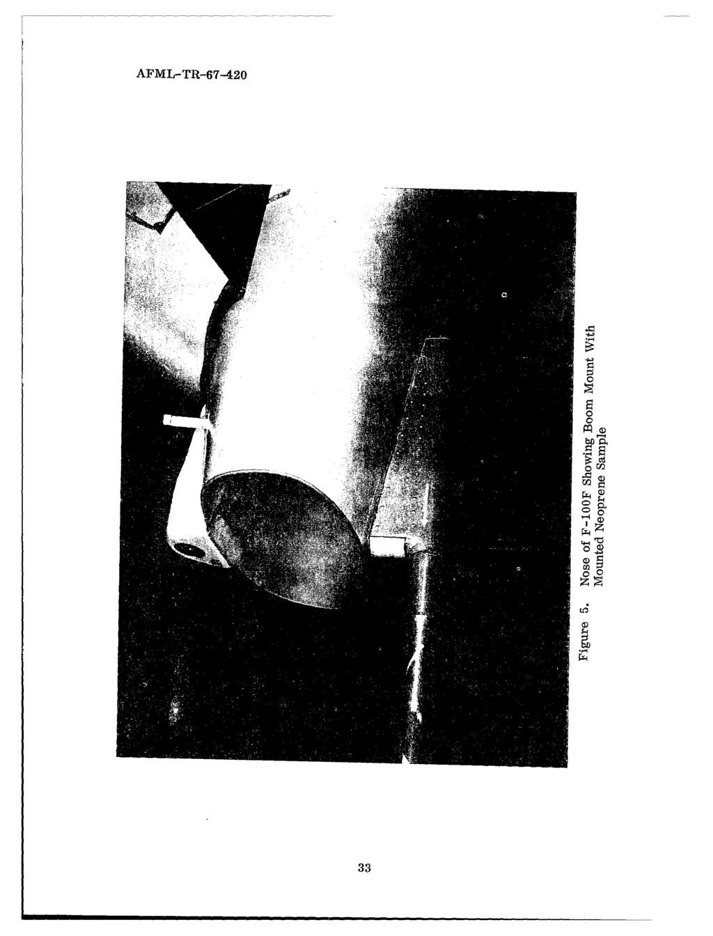
46 AFML-TR
47 Figure 6. Goodrich Boot Sample Number 5 Installed on the Noseboom Mount Figure 7. Deicing Boot Samples on Wing Inboard Leading Edge Sections of F-100F Aircraft; Two Slits Placed in Each Boot for Tests 34
48 Figure 8. Goodrich Boot Samples 1 and 2 on Leading Edge of Left Wing of F-100F Aircraft Figure 9. Goodrich Boot Samples 3 and 4 on Leading Edge of Right Wing of F-100F Aircraft 35

49 S-r Figure 10. Nine Erosion Resistant Samples on Left Horizontal Stabilizer of F-100F Aircraft Figure 11. Two Erosion Resistant Samples on Vertical Stabilizer of F-100F Aircraft 36
50 Figure 12. Nine Erosion Resistant Samples on Right Horizontal Stabilizer of F-100F Aircraft Figure 13. Results of Hail Impact on the Specification Neoprene Sample on Upper Surface of Right Horizontal Stabilizer 37
51 Figure 14. Hail Impact Damage to Specification Neoprene on Lower Surface of Right Stabilizer Figure 15. Specification Neoprene on Inboard Section of Left Stabilizer After Flight 7 38
52 Figure 16. Specification Neoprene Sample on Lower Surface of Left Stabilizer After Hail Encounter During Flight 7 Figure 17. Erosion of Specification Neoprene on Right Stabilizer After Flight 13 39

53 Figure 18. Conedi j~elfction ofoprs LO~ver Prceficatio auifac ~~~f~~ 1 ifct~~nep Neopreni e Uppe Sa o zer Fte light 16 e Surface 40
54 4,m Figure 20. Condition of Specification Neoprene on Lower Surface of Right Stabilizer After Flight 16 Figure 21. The Clear Urethane Sample on Leading Edge Shows an Approximate One-Inch Peel at End of Flights; the Adjacent Pigmented Urethane on Stabilizer Shows No Adverse Effects at the End of Program 41
55 Figure 22. The Clear Urethane on Right Stabilizer Had No Visible Adverse Effects and the Pigmented Urethane Inboard of Clear Urethane Had Approximately One-fourth of the Shoe Peeled at the End of Testing Figure 23. Peeled Segment of Pigmented Urethane on Right Stabilizer After Last Thunderstorm Flight 42
56 Figure 24. Final Condition of Pigmented Urethane Sample on Lower Surface of Right Stabilizer Figure 25. Peeling of Clear Urethane on Right Stabilizer Indicated by Arrow Was Attributed to Overlapping of the Nickel Sample 43
 Were Torn From Sample on Right Stabilizer During Hail Encounter on Flight 7 and Clear Urethane (2) Was Peeled an")
57 Figure 26. Sections of Clear Urethane Tape (1) Were Torn From Sample on Right Stabilizer During Hail Encounter on Flight 7 and Clear Urethane (2) Was Peeled an Additional Amount on the Inboard Edge Figure 27. Close-up of Damage to Clear Urethane on Lower Surface of Right Stabilizer After Flight 7 44
58 Figure 28. After Flight 16 the Clear Urethane on Right Stabilizer was Being Peeled Intact With No Visible Erosion of the Surface Figure 29. Clear Urethane on Lower Surface of Right Stabilizer Was Also Peeling Intact With No Wear on the Surface of the Material 45

59 Figure 30. Pigmented Urethane and Clear Urethane on Left Stabilizer Completed the Tests With No Adverse Effects Figure 31. First Sign of Breakdown of Nickel Sample on Leading Edge of Vertical Stabilizer After Flight 7 46

60 Figure 32. Increased Damage to Nickel Sample on Vertical Stabilizer as of Flight 16 Figure 33. Approximately Two-thirds of the Nickel Sample on the Right Side of the Vertical Stabilizer Was Lost by the End of Program; the Urethane Sample Above the Nickel Had Little Damage 47
61 Figure 34. Damage to Nickel Sample on Right Stabilizer Upon Completing Tests Figure 35. All Urethane Tape on Upper Surface of Left Stabilizer Was Lost During Flight 7 48
62 Figure 36. Urethane Tape Left on Lower Surface of Left Stabilizer After Flight 7 Figure 37. Urethane Tape Remaining on Lower Surface of Right Stabilizer After Hail Encounter During Flight 7 49

63 ~,.. Figure 38. Estane on Inboard Edge of Upper Surface on Left Stabilizer Peeled as a Result of Hail Encounter on Flight 7 Figure 39. Estane on Lower Surface of Left Stabilizer Received Slight Damage During Flight 7 50
64 Figure 40. Additional Peeling of Estane on Upper Surface of Left Stabilizer After Flight 13 Figure 41. Damage to Estane on Lower Surface of Left Stabilizer After Flight 13 51

65 Figure 42. Estane Boot Almost Completely Peeled From Left Stabilizer and Adjacent Neoprene With Insignificant Amount Remaining on Leading Edge on Flight 16 Figv.re 43. Damage to Estane and Neoprene on Lower Surface of Left Stabilizer on Flight 16 52

66 [L-TR Figure 44. Slightly Peeled Section of Estane on Upper Surface of Right Stabilizer Figure 45. Corner of Estane Pulled Slightly From Lower Surface of Right Stabilizer 53
67 Figure 46. Neoprene on Upper Surface of Right Stabilizer Eroded Away During Flight 7 While Adjacent Estane Received No Damage As Figure 47. Neoprefte on Lower Surface of Right Stabilizer Eroded From Aircraft on Flight 7 54
68 Figure 48. One Arrow Points to One of the Cuts in the Leading Edge of Neoprene on Left Stabilizer and the Second Arrow Indicates the Damage to the Hycar Boot During Flight 7 Figure 49. Damage to Neoprene and Hycar Boots on Lower Side of Left Stabilizer After Flight 7 55
69 Figure 50. Increased Deterioration of Neoprene and Hycar Boots on Left Stabilizer Observed By Flight 13 Figure 51. Damage to Neoprene and Hycar Boots on Lower Surface of Left Stabilizer After Flight 13 56
70 Figure 52. Peeling of Hycar Boot on Right Stabilizer During Flight 3 Figure 53. Hail Encounter on Flight 7 Removed Almost All the Hycar Boot From Upper Surface of Right Stabilizer 57
71 Figure 54. Severely Damaged Hycar Boot on Lower Surface of Right Stabilizer After Seventh Thunderstorm Penetration Mission Figure 55. Three-fourths of Hycar Boot Removed From Upper Surface of Left Stabilizer During Flight 16 58
72 Figure 56. Edge of Slit in Deicing Boot Frayed After Flight 2 Figure 57. One-Inch Square Section of Deicing Boot on Right Stabilizer Lost During Flight 2 59
73 Figure 58. Deicing Boot on Left Wing Root With Ruptured Section Figure 59. Increased Failure of Deicing Boot on Left Wing After Flight 3 60
74 Figure 60. Severe Damage to Deicing Boot Caused by Hail and Ice Crystal Impingement During Flight 7 Figure 61. Significant Damage to Deicing Boot on Left Wing Caused by Hail and Ice Crystal Encounter on Flight 7 61
75 Figure 62. Severe Breakdown on Deicing Boot on Right Wing Observed After Flight 13 Figure 63. Increased Visible Erosion of Left Wing Deicing Boot After Flight 13 62

76 AFMI, TR Figure 64. Complete Breakdown' of Deicinkg Boot Onl Left Wing After Figre 5. ect~n f ~icing Boot On Lower Surface of Left Wing Received Little Damfage o lgt1 63
Army Air Forces Specification 7 December 1945 EQUIPMENT: GENERAL SPECIFICATION FOR ENVIRONMENTAL TEST OF
 Army Air Forces 41065 Specification 7 December 1945 EQUIPMENT: GENERAL SPECIFICATION FOR ENVIRONMENTAL TEST OF A. APPLICABLE SPECIFICATIONS A-1. The current issue of the following specifications, in effect
HONTEK HC05XP1 VS. 3M TAPES
 HONTEK HC05XP1 VS. 3M TAPES COMPARISON OF HYDROLYSIS RESISTANCE AND OTHERS A White Paper, July 7, 2010 by Shek C. Hong, Hontek Corporation shek.hong@hontek.com; 161 South Satellite Road, South Windsor,
THE INFRARED SPECTRA AND VIBRATIONAL ASSIGNMENTS FOR SOME ORGANO-METALLIC COMPOUNDS
 ' S C I- THE INFRARED SPECTRA AND VIBRATIONAL ASSIGNMENTS FOR SOME ORGANO-METALLIC COMPOUNDS FRED W. BEHNKE C. TAMBORSKI TECHNICAL DOCUMENTARY REPORT No. ASD-TDR-62-224 FEBRUARY 1962 DIRECTORATE OF MATERIALS
AIR FORCE RESEARCH LABORATORY MATERIALS AND MANUFACTURING
 AIR FORCE RESEARCH LABORATORY MATERIALS AND MANUFACTURING RAIN EROSION TEST APPARATUS Use Policies, Operating Procedures & Specimen Configurations Updated May 2012 University of Dayton Research Institute
TO Approved for public release, distribution unlimited
 UNCLASSIFIED AD NUMBER AD403008 NEW LIMITATION CHANGE TO Approved for public release, distribution unlimited FROM Distribution authorized to U.S. Gov't. agencies and their contractors; Administrative/Operational
SERVICE LETTER TRANSMITTAL SHEET HC-SL Blade - Damage Evaluation for NC10245( ) Blades Installed on (but not limited to) Pilatus PC-12 Aircraft
 Blades Installed on (but not limited to) Pilatus PC-12 Aircraft") TRANSMITTAL SHEET August 01, 2018 This page transmits a revision to Service Letter. Original Issue, dated Revision 1, dated Aug 01/18 Changes are shown by a change bar in the left margin of the revised
TRANSMITTAL SHEET August 01, 2018 This page transmits a revision to Service Letter. Original Issue, dated Revision 1, dated Aug 01/18 Changes are shown by a change bar in the left margin of the revised
S 3 j ESD-TR W OS VL, t-i 1 TRADE-OFFS BETWEEN PARTS OF THE OBJECTIVE FUNCTION OF A LINEAR PROGRAM
 I >> I 00 OH I vo Q CO O I I I S 3 j ESD-TR-65-363 W-07454 OS VL, t-i 1 P H I CO CO I LU U4 I TRADE-OFFS BETWEEN PARTS OF THE OBECTIVE FUNCTION OF A LINEAR PROGRAM ESD RECORD COPY ESD ACCESSION LIST ESTI
Designation: NWI DIF Horizontal Hail impact Standard
 Designation: NWI DIF Horizontal Hail impact Standard 2.1.2015 Standard Test Method for Materials attached to Vertical or Near Vertical Surfaces and Their Resistance to Horizontally Propelled Freezer Ice
UNCLASSIFIED AD ARMED SERVICES TECHNICAL INFORMATION AGENCY ARLINGTON HALL STATION ARLINGT0 12, VIRGINIA UNCLASSIFIED
 UNCLASSIFIED AD 295 456 ARMED SERVICES TECHNICAL INFORMATION AGENCY ARLINGTON HALL STATION ARLINGT0 12, VIRGINIA UNCLASSIFIED NOTICE: When government or other drawings, specifications or other data are
UNCLASSIFIED AD ARMED SERVICES TECHNICAL INFORMATION AGENCY ARLINGTON HALL STATION ARLINGTO 12, VIRGINIA UNCLASSIFIED
 UNCLASSIFIED AD273 591 ARMED SERVICES TECHNICAL INFORMATION AGENCY ARLINGTON HALL STATION ARLINGTO 12, VIRGINIA UNCLASSIFIED NOTICE: When government or other drawings, specifications or other data are
Coating Requirements for Pipelines Installed by Horizontal Directional Drilling John D. Hair, P.E.*
 Coating Requirements for Pipelines Installed by Horizontal Directional Drilling John D. Hair, P.E.* *President, J. D. Hair & Associates, Inc., 2121 South Columbia Avenue, Suite 101, Tulsa, OK 74114-3502;
Rain Erosion Testing of Lightning Diverters
 Rain Erosion Testing of Lightning Diverters PO# 120610 Report Date: 14 January 2011 Revision 2 For Shine Wire Products, Inc. Complied by Edmond (Ned) Tobin and Dr. Trevor Young Department of Mechanical,
REVISIONS SYMBOL DESCRIPTION DATE APPROVAL
 REVISIONS SYMBOL DESCRIPTION DATE APPROVAL - A Initial Release Revised per RN A-159 03/11/2008 07/17/2009 JS SHEET REVISION STATUS SH 1 2 3 4 5 6 7 8 9 10 11 12 13 14 15 16 17 18 19 20 REV A A A A A A
Meteorology. Review Extreme Weather a. cold front. b. warm front. What type of weather is associated with a:
 Meteorology 5.08 Extreme Weather References: FTGU pages 132, 144, 145, 148-155 Air Command Weather Manual Chapters 9 and 15 Review What type of weather is associated with a: a. cold front b. warm front
DEPARTMENT OF ELECTRICAL ENGINEERING DIT UNIVERSITY HIGH VOLTAGE ENGINEERING
 UNIT 1: BREAKDOWN IN SOLIDS 1.) Introduction: The solid dielectric materials are used in all kinds of electrical apparatus and devices to insulate current carrying part from another when they operate at
UNCLASSIFIED AD ARMED SERVICES TECHNICAL INFORMATION AGENCY ARLINGTON HALL STATION ARLINGTON 12, VIRGINIA UNCLASSIFIED
 UNCLASSIFIED AD 295 792 ARMED SERVICES TECHNICAL INFORMATION AGENCY ARLINGTON HALL STATION ARLINGTON 12, VIRGINIA UNCLASSIFIED NOTICE: When government or other drawings, specifications or other data are
PREFERRED RELIABILITY PRACTICES. Practice:
 PREFERRED RELIABILITY PRACTICES Practice No. PD-ED-1239 Page 1 of 6 October 1995 SPACECRAFT THERMAL CONTROL COATINGS DESIGN AND APPLICATION Practice: Select and apply thermal coatings for control of spacecraft
@Copyright 2016 SKAPS Industries.
 SKAPS INDUSTRIES 571 Industrial Pkwy, Commerce, GA 30529 Phone: (706) 336 7000 Fax: (706) 336 7007 E Mail: contact@skaps.com SKAPS GEOCOMPOSITE DROP IN SPECIFICATIONS @Copyright 2016 SKAPS Industries www.skaps.com
MANUAL TT-220 TT-220
 MANUAL TT-220 TT-220 INDEX 1. GENERAL 2 1.1 Scope of applications 2 1.2 Basic working principle 2 1.3 Basic configuration TT220 2 1.4 Technical Parameters 3 1.5 Main functions 3 2. OPERATION OF GAUGE 4
IIIIIIIIIII.EE. EIIIIIIIIIIIIu UKIII/lE
 AN OPTIMAL DESIGN OF SIMPLE SYMTRIC LAMINATES UNDER THE PIRST--ETC(U) MAR O f.j PARK F3361S-?9 -S29 rlaass IFEIO AFAL-TR-8-,TS NL IIIIIIIIIII.EE Ehmhhlllll... EIIIIIIIIIIIIu UKIII/lE AFWAL-TR-81-4175 AN
Temperature Profile for 36 Marker Spheres on 3M 788 ACCR Conductor 3M Company
 Temperature Profile for 36 Marker Spheres on 3M 788 ACCR Conductor 3M Company NEETRAC Project Number: 07-113 June 2007 A Research Center of the Georgia Institute of Technology Requested by: Dr. Colin McCullough
UNCLASSIFIED 'K AD ARMED SERVICES TECHNICAL INFORMATION AGENCY ARLINGTON HALL STATION ARLINGTON 12, VIRGINIA UNCLASSIFIED
 UNCLASSIFIED 'K AD2 8 3 4 4 1 ARMED SERVICES TECHNICAL INFORMATION AGENCY ARLINGTON HALL STATION ARLINGTON 12, VIRGINIA UNCLASSIFIED NOTICE: When government or other drawings, specifications or other data
Experimental Studies on Complex Swept Rotor Blades
 International Journal of Engineering Research and Technology. ISSN 974-3154 Volume 6, Number 1 (213), pp. 115-128 International Research Publication House http://www.irphouse.com Experimental Studies on
Solid-state physics. Laue diagrams: investigating the lattice structure of monocrystals. LEYBOLD Physics Leaflets P
 Solid-state physics Properties of crystals X-ray structural analysis LEYBOLD Physics Leaflets P7.1.2.2 Laue diagrams: investigating the lattice structure of monocrystals Objects of the experiment Evaluating
ANSI/SPRI ES-1 Test Reports UL Classified Products
 Introduction to ES-1 The ANSI/SPRI ES-1 Roof Edge Standard is a reference for those who design, specify or install edge materials used with low slope roofs. This standard focuses primarily on design for
Strain Measurement. Prof. Yu Qiao. Department of Structural Engineering, UCSD. Strain Measurement
 Strain Measurement Prof. Yu Qiao Department of Structural Engineering, UCSD Strain Measurement The design of load-carrying components for machines and structures requires information about the distribution
CONSTRUCTION MATERIALS
 CONSTRUCTION MATERIALS T E C H N O L O G I E S PERFORMANCE TEST REPORT FOR Southern Manufacturing Division of Accord Industries IN ACCORDANCE WITH FLORIDA BUILDING CODE (HIGH VELOCITY HURRICANE ZONES)
SPECIFICATION SS 51/9 400KV COUPLING CAPACITORS FOR POWER LINE CARRIER SYSTEM
 INDEPENDENT POWER TRANSMISSION OPERATOR S.A. TNPRD/ SUBSTATION SPECIFICATION & EQUIPMENT SECTION January 2017 SPECIFICATION SS 51/9 400KV COUPLING CAPACITORS FOR POWER LINE CARRIER SYSTEM I. SCOPE This
NANOBYTE Nanocomposite Coatings for Army Erosion Protection
 NANOBYTE Nanocomposite Coatings for For The Defense Logistics Enterprise Services Program (DLESP) August 4, 2006 Submitted by ManTech Information Systems & Technology 1000 Technology Drive, Suite 3310
Project PAJ2 Dynamic Performance of Adhesively Bonded Joints. Report No. 3 August Proposed Draft for the Revision of ISO
 NPL Report CMMT(A)81 Project PAJ2 Dynamic Performance of Adhesively Bonded Joints Report No. 3 August 1997 Proposed Draft for the Revision of ISO 11003-2 Adhesives - Determination of Shear Behaviour of
BRITISH PHYSICS OLYMPIAD BPhO Round 1 Section 2 18 th November 2016
 BRITISH PHYSICS OLYMPIAD 2016-17 BPhO Round 1 Section 2 18 th November 2016 Instructions This question paper must not be taken out of the exam room. Time: 1 hour 20 minutes on this section. Questions:
The Ice Crystal Weather Threat to Engines
 Jeanne Mason Boeing Commercial Airplanes The Ice Crystal Weather Threat to Engines BOEING is a trademark of Boeing Management Company. Filename.ppt 1 Agenda Introduction Recognition of engine power-loss
Standard Practice for Heat Aging of Plastics Without Load 1
 Designation: D 3045 92 (Reapproved 2003) Standard Practice for Heat Aging of Plastics Without Load 1 This standard is issued under the fixed designation D 3045; the number immediately following the designation
UNCLASSIFIED AD Mhe ARMED SERVICES TECHNICAL INFORMATION AGENCY ARLINGTON HALL STATION ARLINGTON 12, VIRGINIA U NCLASSI1[FIED
 UNCLASSIFIED AD26 8 046 Mhe ARMED SERVICES TECHNICAL INFORMATION AGENCY ARLINGTON HALL STATION ARLINGTON 12, VIRGINIA w U NCLASSI1[FIED NOTICE: When government or other drawings, specifications or other
Accident Prevention Program
 Thunderstorm Accident Prevention Program Thunderstorms - Don't Flirt...Skirt'Em Pilot's Beware! Within the route you intend to fly may lie a summer hazard in wait for the unwary--the Thunderstorm. The
DAMAGE SURVEY OF THE BINGER, OKLAHOMA TORNADO OF MAY 22, 1981
 DAMAGE SURVEY OF THE BINGER, OKLAHOMA TORNADO OF MAY 22, 1981 1. INTRODUCTION James R. McDonald, H. Scott Norville, and Timothy P. Marshall Institute for Disaster Research Texas Tech University Lubbock,
UNCLASSIFIED AD NUMBER LIMITATION CHANGES
 TO: UNCLASSIFIED AD NUMBER AD237455 LIMITATION CHANGES Approved for public release; distribution is unlimited. FROM: Distribution authorized to U.S. Gov't. agencies and their contractors; Administrative/Operational
DESIGN GUIDE FOR GLASS FIBER REINFORCED PLASTIC (GFRP) WIND TURBINE BLADES.
 WIND TURBINE BLADES.") DESIGN GUIDE FOR GLASS FIBER REINFORCED PLASTIC (GFRP) WIND TURBINE BLADES www.wxguardwind.com WXGuard is the new generation of segmented diverters, featuring excellent lightning protection, increased
DESIGN GUIDE FOR GLASS FIBER REINFORCED PLASTIC (GFRP) WIND TURBINE BLADES www.wxguardwind.com WXGuard is the new generation of segmented diverters, featuring excellent lightning protection, increased
Introduction to Geohazard Standard Specification for Simple Drapery
 Introduction to Geohazard Standard Specification for Simple Drapery Up to now, there is no standard specification for geohazard solutions in North America. Often projects specifications are referring to
AFRL-RW-EG-TM
 STINFO COPY AFRL-RW-EG-TM-2010-092 Techniques for Capturing Radiographic Images of High Speed Penetration Events though Sand Bradley A. Breaux, Joshua M. Debes, William L. Cooper Air Force Research Laboratory,
Bending Load & Calibration Module
 Bending Load & Calibration Module Objectives After completing this module, students shall be able to: 1) Conduct laboratory work to validate beam bending stress equations. 2) Develop an understanding of
cot* SEPTEMBER 1965 a CC 0^\ 0 «*«***
 CM 1 1 I >> 1 a, i CO 8! 1 ESD-TR-65-132 vo a! 1 n 1 oc tl. 1 H I 1 -» 1 f- 1 8 CO 1 U4 UJ ESD ACCb^iui^u.-. ESTl Call No._ Copy. No. J Qt 1 ** TM-4187 LIGHT REFLECTIONS FROM SYSTEMS OF PLANE MIRRORS TECHNICAL
UNCLASSIFIED AD NUMBER LIMITATION CHANGES
 TO: UNCLASSIFIED AD NUMBER AD450636 LIMITATION CHANGES Approved for public release; distribution is unlimited. FROM: Distribution authorized to U.S. Gov't. agencies and their contractors; Administrative/Operational
G~OO6oWi's ESTIMATING TIMES TO EARLY FAILURES USING SAMPLE DATA TO ESTIMATE THE WEIBULL SCALE PARAMETER AFFDL-TR-77-89
 ESTIMATING TIMES TO EARLY FAILURES USING SAMPLE DATA TO ESTIMATE THE WEIBULL SCALE PARAMETER Structural Integrity Branch Structural Mechanics Division September 1977 TECHNICAL REPORT AFFDL-TR-77-89 Final
UNCLASSIFIED A30 333~ ARMED SERVICES TECHNICAL INFORMION AGENCY ARLIGTON HALL STATION ARLINGTON 12, VIRGINIA "UNC LASS IFIED
 UNCLASSIFIED A30 333~ 2 8 0 ARMED SERVICES TECHNICAL INFORMION AGENCY ARLIGTON HALL STATION ARLINGTON 12, VIRGINIA "UNC LASS IFIED NOTICe: mhen goverment or other drawings, specifications or other data
DISTRIBUTION SYSTEM ELECTRIC INFRASTRUCTURE RELIABILITY PERFORMANCE INDICATORS
 EB-- Exhibit D Page of DISTRIBUTION SYSTEM ELECTRIC INFRASTRUCTURE RELIABILITY PERFORMANCE INDICATORS FIVE-YEAR HISTORICAL RELIABILITY PERFORMANCE THESL tracks System Average Interruption Frequency Index
FREEZING CONTAMINATION : AIRCRAFT ICING
 FREEZING CONTAMINATION : AIRCRAFT ICING EFFECTS ON AIRCRAFT Different types of accretion Intensity of ice accretion Consequences of accretion Vulnerability factors examples Specific vulnerabilities Detection
A SELF-INDICATING MODE I INTERLAMINAR TOUGHNESS TEST
 A SELF-INDICATING MODE I INTERLAMINAR TOUGHNESS TEST P. Robinson The Composites Centre, Department of Aeronautics, Imperial College London South Kensington, London, SW7 2AZ, UK p.robinson@imperial.ac.uk
Reproduced DOCUMENT SERVICE CENTER ARMED SERVICES TECHNICAL INFORMATION AGENCY U. B. BUILDING, DAYTON, 2, OHIO
 r*' 1, -MrVM«^. * Ji, Reproduced by DOCUMENT SERVICE CENTER ARMED SERVICES TECHNICAL INFORMATION AGENCY U. B. BUILDING, DAYTON, 2, OHIO REEL C ^NOTICE: When Government or other drawings, specifications
Moisture Absorption and Desorption
 Moisture Absorption and Desorption of Composite Materials CHI-HUNG SHEN AND GEORGE S. SPRINGER Department of Mechanical Engineering The University of Michigan Ann Arbor, Michigan 48109 (Received December
Basic Information to Help Select the Correct Propeller
 Propeller Performance Factors - Basic Information to Help Select the Correct Propeller The performance of a propeller in flight involves several complex subjects, and the high performance propellers we
ENGINEERING ASPECTS OF THE 200-INCH HALE TELESCOPE. Bruce Rule Mount Wilson and Palomar Observatories
 ENGINEERING ASPECTS OF THE 200-INCH HALE TELESCOPE Bruce Rule Mount Wilson and Palomar Observatories The engineering designs of the 200-inch Hale Telescope were determined largely by the optical accuracy
ACKNOWLEDGMENTS. & Brother Ltd. for the loan of the blocks of four colour pictures (jacket, frontispiece, and nos. 38 and 48).
.") ACKNOWLEDGMENTS We are indebted to the Air Ministry for permission to reproduce a number of fine pictures taken by the Royal Air Force, to the National Weather Records Centre of the United States Weather
ACKNOWLEDGMENTS We are indebted to the Air Ministry for permission to reproduce a number of fine pictures taken by the Royal Air Force, to the National Weather Records Centre of the United States Weather
Equilibrium in Two Dimensions
 C h a p t e r 6 Equilibrium in Two Dimensions In this chapter, you will learn the following to World Class standards: 1. The Ladder Against the Wall 2. The Street Light 3. The Floor Beam 6-1 The Ladder
PERFORMANCE TEST REPORT. Rendered to: VELUX AMERICA, INC. PRODUCT: SUN TUNNEL Domes TYPES: Acrylic and Polycarbonate
 PERFORMANCE TEST REPORT Rendered to: VELUX AMERICA, INC. PRODUCT: SUN TUNNEL Domes TYPES: Acrylic and Polycarbonate Report No.: E3490.01-106-31 Report Date: 07/13/15 Test Record Retention Date: 06/18/19
NEW STANDARD SEXTANT OF THE U. S. NAVY
 NEW STANDARD SEXTANT OF THE U. S. NAVY Director of the United States of America Hydrographic Office has sent to the International Hydrographic Bureau the following data relating to the new Standard Sextant
How to Use This Presentation
 How to Use This Presentation To View the presentation as a slideshow with effects select View on the menu bar and click on Slide Show. To advance through the presentation, click the right-arrow key or
Physical Properties Testing Technical Bulletin
 Technical Bulletin MANUFACTURER Raven Lining Systems 13105 E. 61 st Street, Suite A Broken Arrow, OK 74012 (918) 615-0020 TENSILE TESTING OF PLASTICS ASTM D638, ISO 527 Tensile tests measure the force
FLIGHT INSTRUMENTS. This manual is dedicated only for IVAO Network activities. This document must not be used in real aviation or in others networks.
 FLIGHT INSTRUMENTS 1. Introduction The flight instruments are the instruments in the cockpit of an aircraft that provide the pilot with flight parameters. The flight instruments are used in conditions
Melton Series. Owners Manual. Lab Centrifuge. Model # s A C, A C, B C, B C, C C, C C, D C, D C
 Melton Series Owners Manual Lab Centrifuge Model # s A-4-115-C, A-4-220-C, B-4-115-C, B-4-220-C, C-4-115-C, C-4-220-C, D-4-115-C, D-4-220-C Serial Numbers 85500 & Above NOTICE Wire this centrifuge according
FLIGHT TEST VALIDATION OF AN ANALYTICAL METHOD FOR PREDICTING TRAILING CONE SYSTEM DRAG FORCE AND DROOP ANGLE REAGAN K. WOOLF
 412TW-PA-12673 FLIGHT TEST VALIDATION OF AN ANALYTICAL METHOD FOR PREDICTING TRAILING CONE SYSTEM DRAG FORCE AND DROOP ANGLE 4 1 2 T W REAGAN K. WOOLF AIR FORCE TEST CENTER EDWARDS AFB, CA 13 AUGUST 2012
FIS Specifications for Flex Poles (Edition May 2008) Original Text: German
 Original Text: German") FIS Specifications for Flex Poles (Edition May 2008) Original Text: German 1 Field of Application and Basic Information The following FIS specifications for flex poles are intended to ensure that flex
FIS Specifications for Flex Poles (Edition May 2008) Original Text: German 1 Field of Application and Basic Information The following FIS specifications for flex poles are intended to ensure that flex
COPPER FOR BUSBARS CHAPTER 4: SHORT-CIRCUIT EFFECTS
 European Copper Institute COPPER FOR BUSBARS CHAPTER 4: SHORT-CIRCUIT EFFECTS David Chapman August 2011 ECI Available from www.leonardo-energy.org Document Issue Control Sheet Document Title: Publication
PUB NLH 185 Island Interconnected System Supply Issues and Power Outages Page 1 of 9
 PUB NLH 1 Page 1 of 1 Q. Provide Hydro s list of outage cause codes and indicate how troublemen are managed and trained to properly use the codes. Explain the method used to report outage causes. A. Hydro
Equilibrium in Three Dimensions
 C h a p t e r 7 Equilibrium in Three Dimensions In this chapter, you will learn the following to World Class standards: Forces in Three Different Axis Wind Load on the Antennae Pole Practice Problem -
TM April 1963 ELECTRONIC SYSTEMS DIVISION AIR FORCE SYSTEMS COMMAND UNITED STATES AIR FORCE. L. G. Hanscom Field, Bedford, Massachusetts
 402 953 TM-3435 O REDUCTON OF SDE LOBES AND PONTNG ERRORS N PHASED ARRAY RADARS BY RANDOMZNG QUANTZATON STEPS TECHNCAL DOCUMENTARY REPORT NO. ESD-TDR-63-155 April 1963 C- C.1 DRECTORATE OF APPLED RESEARCH
I. What are Earthquakes?
 I. What are Earthquakes? A. There is more to earthquakes than just the shaking of the ground. An entire branch of Earth science, called seismology, is devoted to the study of earthquakes. B. Earthquakes
HHPS WHMIS. Rules MSDS Hazard Codes Systems. Biology based. Chemistry based. Safety Symbols. Safety in the Lab. Lab Equipment
 Safety Symbols HHPS WHMIS Safety in the Lab Rules MSDS Hazard Codes Systems Lab Equipment Chemistry based Biology based Safety Symbols We will be discussing two types of Information Systems Hazardous Household
AERO 214. Lab II. Measurement of elastic moduli using bending of beams and torsion of bars
 AERO 214 Lab II. Measurement of elastic moduli using bending of beams and torsion of bars BENDING EXPERIMENT Introduction Flexural properties of materials are of interest to engineers in many different
Task A-1.13: Experimental Measurement of Ice Accretion and Shedding of Rotating Airfoils
 Task A-1.13: Experimental Measurement of Ice Accretion and Shedding of Rotating Airfoils Dr. Jose L Palacios Research Associate jlp324@psu.edu Yiqiang Han Research Assistant ARMY Program Review April 7,
AN ENGINEERING ASSESSMENT OF STRUCTURAL DAMAGE IN THE ALTUS, OK TORNADO: MAY
 (presented at the 13 th Conference on Severe Local Storms, Tulsa, Oklahoma, October 1983, p. 66-69) AN ENGINEERING ASSESSMENT OF STRUCTURAL DAMAGE IN THE ALTUS, OK TORNADO: MAY 11 1982 1. INTRODUCTION
State Math Contest (Junior)
") Name: Student ID: State Math Contest (Junior) Instructions: Do not turn this page until your proctor tells you. Enter your name, grade, and school information following the instructions given by your proctor.
Name: Student ID: State Math Contest (Junior) Instructions: Do not turn this page until your proctor tells you. Enter your name, grade, and school information following the instructions given by your proctor.
TO Approved for public release, distribution unlimited
 UNCLASSIFIED AD NUMBER AD272766 NEW LIMITATION CHANGE TO Approved for public release, distribution unlimited FROM Distribution authorized to U.S. Gov't. agencies and their contractors; Administrative/Operational
Experiment Two (2) Torsional testing of Circular Shafts
 Torsional testing of Circular Shafts") Experiment Two (2) Torsional testing of Circular Shafts Introduction: Torsion occurs when any shaft is subjected to a torque. This is true whether the shaft is rotating (such as drive shafts on engines,
Experiment Two (2) Torsional testing of Circular Shafts Introduction: Torsion occurs when any shaft is subjected to a torque. This is true whether the shaft is rotating (such as drive shafts on engines,
AN INVESTIGATION OF VELOCITY DISTRIBUTION IN TEST SECTION OF WRIGHT BROTHERS WIND TUNNEL. Holden W. Withington
 AN NVESTGATON OF VELOCTY DSTRBUTON N TEST SECTON OF WRGHT BROTHERS WND TUNNEL by Holden W. Withington Submitted in Partial Fulfillment of the Requirements for the Degree of Bachelor of Science in Aeronautical
Aircraft Icing FAR/CS-25, Appendix O and P charts
 Aircraft Icing FAR/CS-25, Appendix O and P charts Prof. Dr. Serkan ÖZGEN Dept. Aerospace Engineering, METU Fall 2015 Outline Appendix O and P - Background Existing CS-25 certification specifications for
Thermal Cube. Custom-built Heat Flux Sensor
 Thermal Cube Custom-built Heat Flux Sensor Specifications and Construction MR. RAZIM REFAI MR. SHAMMAWI ANDERSON DR. ANDRÉ MCDONALD Table of Contents 1. Introduction... 2 1.1 Specifications [1]... 2 1.2
Episode 224: Describing circular motion
 Episode 224: Describing circular motion In this episode, you will introduce the importance of circular motion and explain the need for a centripetal force to keep an object moving along a circular path.
CE 320 Structures Laboratory 1 Flexure Fall 2006
 CE 320 Structures Laboratory 1 Flexure Fall 2006 General Note: All structures labs are to be conducted by teams of no more than four students. Teams are expected to meet to decide on an experimental design
High-Voltage Types Ordering Information, Mica Capacitors
 High-Voltage Types Ordering Information, Mica Capacitors Ordering Information Ordering Information: Order by complete part number, as below. For other options,write your requirements on your quote request
Reference Only Spec. No. JEFL243B 0003F-01 P 1/ 6
 Spec. No. JEFL243B 0003F-01 P 1/ 6 DC Common Mode Choke Coil PLT09HN2003R0P1B Reference Specification 1. Scope This reference specification applies to DC Common Mode Choke Coil (PLT09H Series). 2. Part
Reference Only. Spec. No. JENF243G 0004G-01 P 1 / 12. Ferrite Bead Inductor BL02/BL03 Series
 Spec. No. JENF243G 0004G-01 P 1 / 12 1. Scope Ferrite Bead Inductor B02/B03 Series Reference Specification This reference specification applies Ferrite Bead Inductor (Radial Type). 2. Part Numbering (Ex.)
Doppler Weather Radars and Weather Decision Support for DP Vessels
 Author s Name Name of the Paper Session DYNAMIC POSITIONING CONFERENCE October 14-15, 2014 RISK SESSION Doppler Weather Radars and By Michael D. Eilts and Mike Arellano Weather Decision Technologies, Inc.
DETAIL SPECIFICATION SHEET
 INCH POUND MIL DTL 28803/1E 1 September 2018 SUPERSEDING MIL D 28803/1E 4 September 2013 DETAIL SPECIFICATION SHEET DISPLAY, OPTOELECTRONIC, SEGMENTED READOUT, BACKLIGHTED, STYLE II (LIGHT EMITTING DIODE),
Monitoring Radar Mechanical Drive Systems FAA's choice of monitoring solutions
 Monitoring Radar Mechanical Drive Systems FAA's choice of monitoring solutions Mission-critical Ask the public to name mission-critical systems, and air traffic control radar will be at the top of the
WS-7047TWC Wireless 433 MHz Weather Station With Rainfall and Temperature. Instruction Manual
 WS-7047TWC Wireless 433 MHz Weather Station With Rainfall and Temperature Instruction Manual TABLE OF CONTENTS Topic Page Inventory of Contents 2 Additional Equipment 2 Quick Setup 3 Detailed Setup Guide
All part numbers in the coding below start with "TC-" and end with "203"
 1. Scope: This specification for approval relates to 2. Type designation: The type designation shall be in the following form : All part numbers in the coding below start with "TC-" and end with "203"
Consumer Guide. Southwest Windpower 1801 W. Route 66 Flagstaff, AZ USA
 Consumer Guide wind turbine SITING Southwest Windpower 80 W. Route 66 Flagstaff, AZ 8600 USA www.windenergy.com Introduction Is wind power right for you? Wind generators are an effective source of renewable
UNCLASSIFIED AD DEFENSE DOCUMENTATION CENTER FOR SCIENTIFIC AND TCHNICAL INFORMATION CAMERON STATION, ALEXANDRIA. VIRGINIA UNCLASSIFIED
 UNCLASSIFIED AD.4101 13 DEFENSE DOCUMENTATION CENTER FOR SCIENTIFIC AND TCHNICAL INFORMATION CAMERON STATION, ALEXANDRIA. VIRGINIA UNCLASSIFIED.i NOTICE: Nen government or other dravings, specifications
U.S. DEPARTMENT OF TRANSPORTATION FEDERAL AVIATION ADMINISTRATION. National Policy
 NOTICE U.S. DEPARTMENT OF TRANSPORTATION FEDERAL AVIATION ADMINISTRATION National Policy N 8900.19 Effective Date: 9/20/07 Cancellation Date: 9/20/08 SUBJ: Guidance and Procedures for Dispatching During
Full Scale Structural Durability Test Spectrum Reduction by Truncation Coupon Testing
 Full Scale Structural Durability Test Spectrum Reduction by Truncation Coupon Testing Ogewu C. Agbese F-16/F-22 IFG Service Life Analysis Lockheed Martin Aeronautics Fort Worth, TX, USA ogewu.c.agbese@lmco.com
KINECTRICS NORTH AMERICA INC. TEST REPORT FOR 774-KCMIL 3M TM COMPOSITE CONDUCTOR
 KINECTRICS NORTH AMERICA INC. TEST REPORT FOR 774-KCMIL 3M TM COMPOSITE CONDUCTOR Test Name: SUSTAINED LOAD TEST ON COMPRESSION DEADEND FITTING FOR 774-KCMIL 3M TM COMPOSITE CONDUCTOR AT ROOM TEMPERATURE
TE 75R RESEARCH RUBBER FRICTION TEST MACHINE
 TE 75R RESEARCH RUBBER FRICTION TEST MACHINE Background: The Research Rubber Friction Test Machine offers the ability to investigate fully the frictional behaviour of rubbery materials both in dry and
BRE Client Report. Aging of light pipe materials (4000 hours artificial ageing) Prepared for: James McGowan Monodraught. BRE Watford, Herts WD25 9XX
 Prepared for: James McGowan Monodraught. BRE Watford, Herts WD25 9XX") BRE Client Report Aging of light pipe materials (4000 hours artificial ageing) Prepared for: James McGowan Date: 24 February 2015 Report Number: 298-109 Issue: 4 BRE Watford, Herts WD25 9XX Prepared for:
BRE Client Report Aging of light pipe materials (4000 hours artificial ageing) Prepared for: James McGowan Date: 24 February 2015 Report Number: 298-109 Issue: 4 BRE Watford, Herts WD25 9XX Prepared for:
A Description of Convective Weather Containing Ice Crystals Associated with Engine Powerloss and Damage
 A Description of Convective Weather Containing Ice Crystals Associated with Engine Powerloss and Damage The Boeing Company 1 Photo: courtesy of Ian McPherson The Boeing Company acknowledges the contributions
ELEMENTARY SCIENCE PROGRAM MATH, SCIENCE & TECHNOLOGY EDUCATION. A Collection of Learning Experiences WEATHER Weather Student Activity Book
 ELEMENTARY SCIENCE PROGRAM MATH, SCIENCE & TECHNOLOGY EDUCATION A Collection of Learning Experiences WEATHER Weather Student Activity Book Name This learning experience activity book is yours to keep.
THE LONGINES SIDEROGRAPH
 THE LONGINES SIDEROGRAPH (According to a communication received from the Longines Watch Company Ltd, Francillon St. Imier, Switzerland). Formerly, in order to fix his position, the naval officer was obliged
Physics12 Exam Review Questions
 Physics12 Exam Review Questions 1) You are making a circular turn in your car on a horizontal road when you hit a big patch of ice, causing the force of friction between the tires and the road to become
PUMP PERFORMANCE MEASUREMENTS Jacques Chaurette p. eng. April 2003
 PUMP PERFORMANCE MEASUREMENTS Jacques Chaurette p. eng. www.lightmypump.com April 003 Synopsis This article examines how to take flow and pressure measurement and then calculate the total head of a pump
A.R.M. 52 PLOW With QUICK ATTACH MOUNTING SYSTEM MODEL NUMBER BLACK MODEL NUMBER GRAY. Owner s Manual
 70 8TH AVE W PO BOX 7 SPENCER, IA 0 PHONE: 7-6-9 FAX: 7-6-08 SERVICE: 800-8- E-MAIL: ccac@cyclecountry.com www.cyclecountry.com A.R.M. PLOW With QUICK ATTACH MOUNTING SYSTEM MODEL NUMBER 0-00 BLACK MODEL