Oberebenestrasse Bremgarten Switzerland Tel Fax
|
|
|
- Barnard Wilkinson
- 5 years ago
- Views:
Transcription

1 Oberebenestrasse Bremgarten Switzerland Tel Fax Winding Resistance Meter - 50 Amp/2 Channel Model: WR50-12 Instruction manual 1.01 WR50-12 preliminary
2 Table of Contents Section Page Table of Contents 2 Safety Precautions Uncrating Procedure Technical Specifications Introduction Advantages & Features 6 System Details Limitations of Testing 7 Discharging the Transformer windings 7 Front Panel Description Operation Getting started Archive The General Setup Menu Temperature measurements Option TP Temperature correction Setting the Clock Service Mode Basic Instructions Quick Test Trouble Shooting Error Messages Warranty Appendix A Update the Firmware 22 Appendix B License Key 23 Appendix C Heat Run Test (cooling curve) (Option) 25 RAYTECH Switzerland All rights reserved. No portion may be reproduced without written consent 2
3 SAFETY PRECAUTIONS! 1-0 The following safety precautions must be observed during all phases of operation, service, and repair of this instrument. By purchasing this equipment the purchaser assumes all liability for the operation and use of this equipment. The intended use of the instrument, its design and manufacture, is to be conducted within the precautions or other specific warnings located within this manual. Failure to comply with these precautions and other specific warnings violates safety standards of design, manufacture, and intended use. Raytech Switzerland assumes no liability for the operation and use of this equipment. SAFE OPERATION Only qualified knowledgeable persons should be permitted or attempt to operate this test equipment. All test personnel should fully familiarize themselves with the correct application and operation of this and all test equipment prior to operation. Persons directly and indirectly engaged in the operation of this test equipment should keep clear of all high voltage apparatus while conducting tests and measurements. BEFORE APPLYING POWER Read this manual carefully before operating the system. The WR50-12 is line operated. The system operates from a wide range power input from 100 to 250 Vac 50/60Hz. DO NOT OPERATE IN AN EXPLOSIVE ATMOSPHERE Do not operate the instrument in the presence of flammable gases or fumes. KEEP AWAY FROM LIVE CIRCUITS Operating personnel must not remove instrument covers. Component replacement and internal repairs must be made by qualified service personnel. Do not replace components with power cable connected. To avoid injuries, always disconnect power, discharge circuits, and remove external voltage sources before touching components. DO NOT SUBSTITUTE PARTS OR MODIFY INSTRUMENT Because of the danger of introducing additional hazards, do not install substitute parts or perform any unauthorized modification to the instrument. Return the instrument to a Raytech Switzerland service department for service to ensure proper operation and that safety features are maintained. Instruments, which appear damaged or defective, should be made inoperative and secured against unintended operation until qualified service personnel can repair them. TEST WARNING! Do not use on live circuits. RAYTECH Switzerland All rights reserved. No portion may be reproduced without written consent 3


4 UNCRATING PROCEDURE: 2 0 Unpack your new WR50-12 and check to see that you have the following standard items: WR50-12 Instrument Cable Set, consisting of: - Potential Leads 1. Channel - Potential Leads 2. Channel - Current Lead - - Jumper Lead - Current Lead + If any of the above items are missing or damaged contact your local representative or Raytech Switzerland immediately. The test leads may be ordered other than shown. * Note: The WR50-12 Field case is a waterproof design that incorporates an automatic pressure relief valve that will adjust to various atmospheric changes, i.e... Airplane Travel, High altitudes, etc... The valve is designed to be water resistant. RAYTECH Switzerland All rights reserved. No portion may be reproduced without written consent 4
5 TECHNICAL SPECIFICATIONS 3 0 MODEL: WR50-12 SIZE: L: 521 mm (20.5 ) W: 432 mm (17 ) H: 216 mm (8.5 ). WEIGHT: 16.6 kg (36.6 lbs.). INPUT POWER: 90 to 264 Vac (1.5kW max.), 50/60 Hz, Automatic ranging. OUTPUT VOLTAGE: 0 to 50V DC. TEST CURRENT: User Selectable: Ampere. PANEL DISPLAY: Color LCD with back lighting and touch screen. FRONT PANEL: Sealed anodized. INTERFACE: 9 Pin RS232 Serial / 2 USB 1.1 MEMORY STORAGE: Stores up to complete test results. RESISTANCE RANGE : 0.00 µω to kω MEASUREMENT PARAMETERS: Current Range Measuring Range Accuracy Resolution Amp 0.00 µω Ω ± 0.1% Rdg ± 0.05 µω 5 Digits or 0.05 µω Amp 0.0 µω Ω ± 0.1% Rdg ± 0.1 µω 5 Digits or 0.1 µω Amp 0.0 µω Ω ± 0.1% Rdg ± 0.2 µω 5 Digits or 0.2 µω Amp 0.0 µω Ω ± 0.1% Rdg ± 0.5 µω 5 Digits or 0.5 µω Amp 0.0 µω Ω ± 0.1% Rdg ± 1 µω 5 Digits or 1 µω Amp mω Ω ± 0.1% Rdg ± 2 µω 5 Digits or 2 µω Amp mω Ω ± 0.1% Rdg ± 5 µω 5 Digits or 5 µω Amp 0.00 mω Ω ± 0.1% Rdg ± 10 µω 5 Digits or 10 µω mamp 0.00 mω Ω ± 0.1% Rdg ± 20 µω 5 Digits or 20 µω mamp 0.00 mω kω ± 0.1% Rdg ± 50 µω 5 Digits or 50 µω mamp Ω... 5 kω ± 0.1% Rdg ± 100 µω 5 Digits or 100 µω - 10 mamp 5 kω kω ± 0.1% Rdg ± 1 Ω 5 Digits or 1 Ω - 10 mamp 10 kω kω ± 0.8% Rdg ± 20 Ω 5 Digits or 20 Ω TEMPERATURE : Operating: -10 C to 60 C Storage: -20 C to 70 C CABLE SET / ACCESSORIES Current and potential lead set 10 meters, Jumper cabel, Instruction Manual. FEATURES: Standard Items Charges inductive loads up to 1500 Henry Heavy-duty protection circuitry Simple touch screen operation Data exchange with an USB-Key 3 Temperature channels High power DC Supply ( 50A/50V ) DC Current adjustable for resistance values from 0.0 µω to 100 kω Fastest Discharge unit on market ( more then 10 times faster ) Discharge Indicator visible and audible indicator for discharge status Demagnetizing Circuit (world unique) Warning device output to show transformer under test Emergency stop push button immediately turns off power and starts discharging Data transfer to internal Printer Data Storage of up to measurements Mounted in rugged case for field-testing. 2 Year standard warranty OPTIONS: Part No - TP 01 External Temperature probe assembly Part No - AHRT 01 Heat Run Test * Specifications are subject to change at anytime. RAYTECH Switzerland All rights reserved. No portion may be reproduced without written consent 5
6 INTRODUCTION 4-0 Raytech Digital Winding Resistance meter WR50-12 is the successor of the very successful type WR50-2. It is the improved type with the world unique demagnetizing circuit. It is designed for high degree of accuracy for the measurement of very low resistance of inductive loads. This technology was then packed into a portable test system for use by apparatus manufacturers, rebuild shops, and electrical maintenance crews. Ease of use: This intelligent system has an easy to use operation screen, which allows quick selection of the current level to be measured. Just point with your finger on the item you want to change or activate. Impressive Accuracy: The WR50-12 is a high precision, fully automatic, multi-microprocessor based system. This system is designed for highly accurate readings on-site with laboratory precision. Unique Measuring Technique: This newly designed technique of measurement incorporates a high precision measurement circuit, a unique power source and the fastest discharge unit on market. Extensive filtering and high precision standards are used within the test system. The system is capable of precision measurements to 50 A. Operation: The WR50-12 applies a preset current level, selected by the User. The 50V power source quickly charges the load and the results of the test are displayed within a few seconds automatically. The results are reported on the easy to read color LC display and can be stored or printed. Compact Design: The WR50-12 is one of the most lightweight systems available that comes complete with its own rugged waterproof Fieldcase. Simple Maintenance: There is No maintenance required. There is No calibration procedure (No potentiometers to turn). This is due to the utilization of high precision components in the design. Advanced Protection: Upon powering on the system initializes itself with a self-calibrating, circuit checking sequence. If any problems are detected during this initialization period, or during operation, the operator is immediately notified. The system constantly monitors the condition when turned on. The WR50-12 has extensive protection built in to the circuitry. This is one of the many reasons we can extend our warranty to 2 years. Advantages & Features: Highest accuracy and Precision of any high current test system. Automatic measurements of Low Resistance from 0.1µΩ...10kΩ. Demagnetising Circuit (world unique) Microprocessor based system with internal storage for over test results. Printing and Storage of test results while the test system is measuring. Complete automatic calibration system and system diagnostics. Standard USB 1.1 & RS232 (serial) Interface. Pure filtered DC Power source for the highest accuracy readings. Automatic, high efficiency cooling system to dissipate internal temperatures. Automatic shut off for over-temperature condition Panel mounted Emergency Stop Switch Wide input power source range Lightweight and Portable, less than 16.6 kg (36,6 Lbs.) 2 Year standard warranty RAYTECH Switzerland All rights reserved. No portion may be reproduced without written consent 6
7 SYSTEM DETAILS: 5-0 System Check: The instrument is Line operated. The system is designed to be used with voltage power sources (mains power) between Vac 50/60Hz. The system performs a self-check each time that it is powered on. The User should always visually inspect all connectors, cables and devices to be measured to avoid any safety issues. Limitations of Winding Resistance Testing: In general, there are no limitations on testing low or high inductive windings of transformers. The test system is specially designed to test all transformer windings. Discharging the Transformer windings: The WR50 systems are specialized systems designed to measure Transformer windings. These systems are equipped with heavy-duty discharge circuits that are very unique in the market! The internal discharge circuit dissipates the stored energy in the transformer windings with Constant Power Discharge Circuit that is unique to all transformer winding test systems. That is the reason why Raytech systems can discharge transformers more then 10 times faster then any other system on the market. If a cable happens to fall off during test, the system will STILL discharge the test object safely with the automatic Constant Power Discharge Circuit. The Potential Test Leads are part of the safety circuit and require the ability to discharge a transformer in the case where a current lead may become detached. DO NOT USE A SMALLER GAUGE POTENTIAL CABLES THEN THE ORIGINAL RAYTECH CABLES SUPPLIED! Low Resistance Testing: The WR50-12 utilizes a 4 wire measuring technique on each Channel. The points where the potential leads are connected determine the resistance reading. The test set employs a very simple principle of Ohm s law: R=U/I R = Resistance, U = Voltage, I = Current RAYTECH Switzerland All rights reserved. No portion may be reproduced without written consent 7


8 FRONT PANEL DESCRIPTION: 6-0 Power Emergency OFF Power cord connection Press to stop On/Off switch Turn Clockwise Accepts V AC to release 50/60 Hz Interfaces: USB 1.1 USB 1.1 Serial RS232 Bi-directional Host Device Female 9 pin connector RAYTECH Switzerland All rights reserved. No portion may be reproduced without written consent 8
 6 0 Test Connections: +Current = Positive Current connection +Channel 1= Positive Potential (voltage) connection of Channel 1 -Channel 1= Negative")

 Danger condition Display: Shows that Current is flowing.")
9 FRONT PANEL DESCRIPTION: (cont.) 6 0 Test Connections: +Current = Positive Current connection +Channel 1= Positive Potential (voltage) connection of Channel 1 -Channel 1= Negative Potential (voltage) connection of Channel 1 +Channel 2= Positive Potential (voltage) connection of Channel 2 -Channel 2= Negative Potential (voltage) connection of Channel 2 -Current = Negative Current connection Temperature Probe connection: External Flashlight: Three 2 pin Connections for optional external temperature probes ( TP 01 ) Connection for an external Flash Light or Beeper to indicate a Dangerous condition. Working contact Pin (230Vac 2A) Danger condition Display: Shows that Current is flowing. Shows that you bought Shows that test Object is Don t remove any Cable! the right Instrument. in Safe condition. RAYTECH Switzerland All rights reserved. No portion may be reproduced without written consent 9

 connections on the front plate +Channel 1 & -Channel 1 and +Channel 2 & -Channel 2 are the Potential or Voltage leads.")
10 OPERATION: 7-0 WARNINGS! BEFORE OPERATING THIS OR ANY OTHER TEST EQUIPMENT READ ALL SAFETY WARNINGS AND UNDERSTAND THEM FULLY. OPERATION: This section describes a typical, step-by-step, operation of the WR50-12 Open the protection lid of the case and attach the test leads and the power cord to the test set. The Two (2) connections on the front plate +Current & -Current are the current leads. The Four (4) connections on the front plate +Channel 1 & -Channel 1 and +Channel 2 & -Channel 2 are the Potential or Voltage leads. By connecting a test specimen to the Current leads and applying the potential leads across the specimen the resistance readings will be determined. GETTING STARTED: 7-1 Turn the Power switch, located at the power input connector to the I position. The Initial screen will appear During this Time, the Instrument is performing the initial calibration. RAYTECH Switzerland All rights reserved. No portion may be reproduced without written consent 10
11 GETTING STARTED: (cont.) 7-1 When everything is ok, the main screen will appear: The WR50-12 incorporates a touch-screen display for all input parameters. Select the current range to measure by touching the word Range. The following screen appears: Now you may select the current you want to choose by tapping on that range ( p.e. 10 A ). There are 3 buttons to set a user selectable current, adjust the current by pressing Set After selection of the required range, start the measurement by just touching the Start Button. RAYTECH Switzerland All rights reserved. No portion may be reproduced without written consent 11
12 At the start of a test a single audible beep will be heard as a reminder that the test system is about to charge the inductive windings. Operators should be careful not to remove any cables while the test system is measuring. During the measurement you will see the following: The operator may press Store at anytime to store a complete record. The current continues to flow and the system will measure until touching Stop halts the Measurement. DO NOT TOUCH, MOVE OR MANIPULATE THE MEASURING CABLES BEFORE YOU HEAR TWO BEEPS AND THE DISPLAY AND LAMPS SHOW A SAFE CONDITION! RAYTECH Switzerland All rights reserved. No portion may be reproduced without written consent 12

 indicates that no temperature probe was plugged into connector Temp 1 on the front panel.")
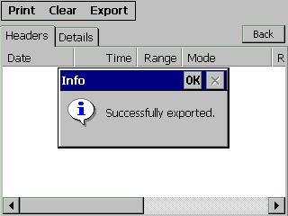
13 ARCHIVE: 7-2 To access the Archive (Memory locations), touch Results on the screen and then Show on the next screen. Remember: Not all menus are active during the measuring process. The Headers column displays the listed stored results. Saving multiple results during the measuring process stores the data under one header location. All the stored results linked to a particular header are accessible by touching Details By touching the arrows on the bottom left or right, you will see all the stored results of that selected measurement. An empty field (p.e. T1) indicates that no temperature probe was plugged into connector Temp 1 on the front panel. The column Time is the time that has past after starting the measurement process. By touching one of the Menus in the Menu-bar you have the following options: Print Printing selected Measurement Printing ALL the Measurements Clear Erase selected Measurement Erase ALL Measurements Export Store the results to an USB-Device (p.e. USB Key) RAYTECH Switzerland All rights reserved. No portion may be reproduced without written consent 13


14 THE GENERAL SETUP MENU: 8-0 To access the Setup Menu, select (touch) Setup and then General Service Mode Not for public use. See chapter 12.0 Firmware Update To update or change the built in Firmware See Appendix A About Check the version of the installed Firmware. See Appendix A Clock Settings Setting the clock. See chapter 11.0 Show Mouse Cursor Show or hide the Mouse Cursor. Usefully if you operate with a mouse at USB If you touch R1 or R2, the following screen appears Now you can enter any Name for R1 and R2 you want. If you are done, press Hide RAYTECH Switzerland All rights reserved. No portion may be reproduced without written consent 14

15 TEMPERATURE MEASUREMENTS: 9-0 The system allows up to Three (3) temperature probes to be used with the system for the purpose of recording temperatures. Optional Part Number: TP 01, can be purchased for this purpose. Recording the temperature of the device under test is highly recommended due to the characteristics of the increase of resistance of a metallic object as its temperature increases. There are temperature compensation tables for Copper and Aluminum available to calculate the conversion factor to a known reference temperature. The WR50-12 is a very accurate and precise test system. To take full advantage of this high accuracy, the temperature of the device under test should be recorded. The TP 01 temperature probe is mounted to a flexible extension cable that plugs into the front panel of the WR This option enables the User to record the ambient temperature and/or the actual temperature of the device under test. The WR50-12 will automatically sense when the optional temperature probes, TP 01, are connected to it. The temperature will be displayed on the instrument screen during a test and will appear when a printed report is requested. The temperature, as well as the test results, can be saved into memory. TEMPERATURE CORRECTION: 10-0 The WR50-12 can, fully automatic, correct the measured values regarding the temperature. To activate this feature press Setup and then Temp. Correction In this example, the measured object is copper and will be corrected to 25Degrees Celsius based on the temperature on Temperature channel 1. If you do not have a Raytech Temperature probe, activate the Ext box and fill in the temperature you measure with your other temperature probe. The correction follows the formula: Rs=Rm[(Ts+Tk)/(Tm+Tk)] where Rs is resistance at desired temperature, Ts Rm is measured resistance Ts is desired reference temperature Tm is the temperature at which resistance was/is measured Tk is for copper, 225 for aluminum (aluminum may be as high as 240) If you are used to a correction with alpha25 you can calculate the Tk by the formula: Tk=(1/alpha25)-25 RAYTECH Switzerland All rights reserved. No portion may be reproduced without written consent 15

16 TEMPERATURE CORRECTION: (cont.) 10-0 If you are using another Tk then the standards for cooper or aluminum, activate the box User defined and input the Tk in the box below. When Temperature correction is activated, the main screen looks as follows: The T in the box at each measuring channel shows that the displayed resistance value is corrected (in this example to 25Degrees using Tk of cooper and referring to Temperature probe 1). In case the T in the box is red, ther is no temperature probe connected. If you want to see the real (not corrected) value, just hit the T and it looks like follows: The crossed T shows that the displayed resistance value is NOT corrected. No matter if you activate the correction in the display or not, the corrected AND the uncorrected values are stored. RAYTECH Switzerland All rights reserved. No portion may be reproduced without written consent 16


17 SETTING THE CLOCK: 11-0 To set the clock, go to the main screen and select (touch) the Setup and then the Clock Settings Set the desired values by touching the Up or Down arrows next to the related locations. By selecting (Touching) Set the Clock will be activated and set. SERVICE MODE 12-0 In the Setup Menu is a Service Mode. This Mode is for internal service use only and not accessible. A login code is required. Touch # to Exit. RAYTECH Switzerland All rights reserved. No portion may be reproduced without written consent 17
18 BASIC INSTRUCTION: 13-0 WARNINGS! BEFORE OPERATING THIS OR ANY OTHER TEST EQUIPMENT READ ALL SAFETY WARNINGS AND UNDERSTAND THEM FULLY. WARNINGS! BEFORE USING THE BASIC OPERATING INSTRUCTIONS THE OPERATOR SHOULD BE COMPLETELY FAMILIAR WITH THE TEST SYSTEM AND THIS TYPE OF TESTING. QUICK TEST: 13-1 This section outlines the basic measurement instruction, step by step, for the WR These are basic instructions, simplified, for the trained and qualified operator. 1. Connect the test leads (2 Current / 2 or 4 Potential) to an un-energized device to be measured. 2. Connect the Safety Ground on the front panel to known good Earth Ground. 3. Turn on the system. 4. Touch Range. 5. Select the Current Range. 6. Select (Touch) Start to start the test. 7. When results are displayed and are stable press Store. 8. To end the test press Stop. 9. Wait for Safe Status display RAYTECH Switzerland All rights reserved. No portion may be reproduced without written consent 18
19 Troubleshooting GENERAL 14 0 At powering on, the WR50-12 internal calibration and check sequence is performed. Upon completion of the check sequence the test set will proceed to the Main Screen. Should there be any problem with the test set an error message will appear. SYSTEM DOES NOT DISPLAY ANYTHING: 1. Check the display for any Initialization. 2. Check the fuse. The fuse is located in the Power switch / plug connector. SYSTEM POWERS ON BUT THE DISPLAY FADES OUT OR BLINKS: 1. Check the input power line for faults. 2. If an extension cord is being used, check the size and condition of. An extension cord should not exceed 25 feet long and should be at least #12 wire minimum. TEST CURRENT CANNOT BE TURNED ON. 1. Is the Emergency stop switch pushed in? Turn to release it. 2. Is the system connected in an excessive interference area? ERRATIC OR ERRONEOUS READINGS Possible causes 1. Test lead damaged or not connected. 2. Poor test lead connection. 3. Poor supply power. Check extension cords, plugs cables carefully. 4. Test set attached to a Live load or high interference load. The WR50-12 is designed to be trouble free. If problems or questions do arise please contact your nearest Dealer or our service support group in Switzerland. Office Tel , Office Fax RAYTECH Switzerland All rights reserved. No portion may be reproduced without written consent 19


 are still active.")
20 ERROR MESSAGES 15 0 The emergency switch is activated In this condition it is impossible to start a measurement. Exiting this message screen by touching OK without releasing the emergency switch, The system will revert to a pretest or main screen similar to the following screen: Because the emergency switch is still depressed, you are not able to start a new measurement. All other features of the system ( storing, printing ) are still active Attempt to store results to the USB-key without any device key plugged to the WR50-12 Plug the USB-key in and try again. The following will appear: RAYTECH Switzerland All rights reserved. No portion may be reproduced without written consent 20
21 WARRANTY RAYTECH Switzerland shall at their option and expense, repair, replace or newly provide any parts or services that prove to be defective within the warranty limitation periodirrespective of the operating time of the test equipment provided that the cause of the defect occurred prior to the time at which the risk was passed. 2. Warranty claims are subject to a warranty limitation period of 24 months from the date of shipment. 3. The purchaser is obligated to immediately notify RAYTECH Switzerland in writing form of any defects of the supplied test equipment. 4. RAYTECH Switzerland must always be given the opportunity to rectify a defect within a reasonable time. The purchaser shall grant an adequate time within the test equipment shall be repaired. 5. RAYTECH Switzerland covers the costs associated with the repair of the defect. Especially the costs for the material and work. Cost for sending the faulty test equipment shall be borne by the purchaser. RAYTECH Switzerland shall not be liable for material damage, or financial loss due to the loss of production, loss of data, loss of information, data or interest, regardless of their legal basis. 6. Warranty claim rights on replacement parts as well as repair of defective parts shall expire after 12 months. 7. Warranty limitation period shall be extendable according to the price list. The purchaser has the right to extend the warranty period by purchasing additional warranty years. Limitation of Warranty The foregoing warranty shall not apply to defects resulting from improper and unauthorized modifications or misuse and abuse of the product, negligence, alteration, modification, faulty installation by the customer, customer s agents or employees. Attempted or actual dismantling, disassembling, service or repair by any person, firm, or corporation not specifically authorized in writing by Raytech Switzerland. Defects caused by or due to handling by carrier, or incurred during shipment, trans-shipment, or other move. Inadequate maintenance by the customer, second source supplied software or interfacing, operation outside the environmental limits, or improper site preparation. Exclusive remedies provided herein are the customer s sole and exclusive remedies. Raytech Switzerland shall not be liable for any damages resulting from the use of this equipment whether direct, indirect, special, incidental, or consequential damages, or whether based on contract, tort, or any other legal theory. NO OTHER WARRANTY IS EXPRESSED OR IMPLIED. Arbitration 1. All disputes arising out of or in connection with the contract between the purchaser and RAYTECH Switzerland and including those regarding the legal validity of this contract and this arbitration clause shall be settled out of court and shall be referred to arbitration for final decision. 2. Any disputes between the purchaser and RAYTECH Switzerland shall be settled according to the rules of settlement and arbitration of the chamber of commerce in Zurich by one or more arbitrators appointed also according to the rules of arbitration of the chamber of commerce in Zurich Switzerland. RAYTECH Switzerland All rights reserved. No portion may be reproduced without written consent 21


22 APPENDIX A UPDATE THE FIRMWARE: You can easily check the Firmware Version installed on your WR In the Main Display touch Setup - and then the About key A newer Version may be available and can be found at this link: Download this new version and store it to the USB Key. Switch the WR50-12 on and plug the USB Key into the USB Port of the Instrument. Press Setup and then Firmware Update : Select the Version you want to install and then press Install The only thing you have to do now is to wait until the system reboots. RAYTECH Switzerland All rights reserved. No portion may be reproduced without written consent 22


23 APPENDIX B LICENSE KEY Checking State of Licenses Press License Manager In the License Manager the Status of the Licenses can be checked. Press Enter New Licenses Key for entering a new License. RAYTECH Switzerland All rights reserved. No portion may be reproduced without written consent 23

24 Enter the License in the format xxx.xxx.xxxx and press Check The Licensekey is valid only for a specific WR50. Renting licenses can be entered only ones. RAYTECH Switzerland All rights reserved. No portion may be reproduced without written consent 24

25 APPENDIX C WR50 - Heat Run Test (cooling curve) Setup Activate Interval Mode and select the interval time ( time in sec between measuring points) and the number of data points. Deactivate Temperature correction RAYTECH Switzerland All rights reserved. No portion may be reproduced without written consent 25

26 Start of the pre-measurement timer During the heat run test the transformer was heated up by an external power source. At the moment of the switching off the power source, the heat run timer has to be started. Press Timer Button on the main screen. The timer is now running The timer can be stopped by pressing the button a second time. RAYTECH Switzerland All rights reserved. No portion may be reproduced without written consent 26


27 Measurement is started by pressing the Start -Button. Starting Measurement After charging the transformer, the systems waits until the results are stable. Then results are stored automatically. After storing the last measurement the WR50 is stopped and the transformer is discharged. With the Stop -Button the measurement can be interrupted. After stopping the measurement, the timer is not stopped. Further measurements (other windings on the same transformer) can be made. RAYTECH Switzerland All rights reserved. No portion may be reproduced without written consent 27

28 Analyzing the HRT results. Select the Data-set in Result Screen Press Detail -Tab to see all stored results. Select in the menu HRT / Analyze The graph of the measured values is shown. Press Analyze You ll be asked for Approximation Model to calculate the Value of the Winding at time = 0. RAYTECH Switzerland All rights reserved. No portion may be reproduced without written consent 28
")


29 Select the Approximation Model (Exp)onential or (Lin)ear After setting the Model press Analyze The value of the approximation R(t=0) is shown. Meaning of the Parameters When Linear Approximation was selected R0: Value of the Windingresistance at time t= 0 m: devation dr/dt in %/ min Cor: Correlation of the approximation RAYTECH Switzerland All rights reserved. No portion may be reproduced without written consent 29


30 When Exp Approximation was selected R0: Value of the Winding resistance at time t= 0 tau: time constant R : Value of the Winding resistance at time t Cor: Correlation of the approximation The approximation and the measured values Showing the graph in C When the resistance of the Winding and the material is known, all the values can be expressed as C. Enter the Value of the Winding at reference temperature and the temperature coefficient of the conductor. Values shown as Temperature. RAYTECH Switzerland All rights reserved. No portion may be reproduced without written consent 30
RAYTECH USA, Inc. 90C Randall Avenue, Woodlyn, PA USA Tel Fax Instruction Manual
 RAYTECH USA, Inc. 90C Randall Avenue, Woodlyn, PA 19094 USA Tel. 610 833 3016 Fax. 610 833 3018 Instruction Manual 50 Amp / 3 Channel Winding Resistance Meter Model: WR50-13 Preliminary Instruction Manual
Field Pro Operation and Installation Manual
 Field Pro Operation and Installation Manual Xtreme Research Corporation SkyScan Division P.O. Box 336, Port Richey, FL 34673-0336 1-800-732-0665 Table of Contents 1. Installation 3 2. Operation 5 3. Care
WeatherHub2 Quick Start Guide
 WeatherHub2 Quick Start Guide Table of Contents 1 Introduction... 1 2 Packing List... 1 3 Connections... 1 4 IP Addressing... 2 5 Browser Access... 3 6 System Info... 3 7 Weather Station Settings... 4
Lamp and Control Panel (Lamp Panel)
") www.reinhausen.com Lamp and Control Panel (Lamp Panel) Operating Instructions BA 47/0 EN NOTE! Changes may have been made to a product after going to press with this documentation. We expressly reserve
www.reinhausen.com Lamp and Control Panel (Lamp Panel) Operating Instructions BA 47/0 EN NOTE! Changes may have been made to a product after going to press with this documentation. We expressly reserve
VIBRATION METER. Instruction Manual.
 VIBRATION METER 840063 Instruction Manual CONTENTS Title Page I. Introduction... 2 II. Panel Description... 3 III. Operating Instructions A. General Measurement Procedures... 3~4 B. Peak... 5 C. Data Hold...
SkyScan EWS-PRO - Manual -
 INTRODUCTION SkyScan EWS-PRO - Manual - EWS-Pro gives you advance weather warning technology you can use at home, indoors or out, and take wherever you go, for any kind of outdoor activity. Your EWS-Pro
QUANTUM CONCEPT. Swimming User s Manual
 QUANTUM CONCEPT Swimming User s Manual 480.508.0 Version.4 Edition July 05 Documentation Updates Swiss Timing Ltd. reserves the right to make improvements in the products described in this documentation
SC125MS. Data Sheet and Instruction Manual. ! Warning! Salem Controls Inc. Stepper Motor Driver. Last Updated 12/14/2004
 SC125MS Stepper Motor Driver Salem Controls Inc. Last Updated 12/14/2004! Warning! Stepper motors and drivers use high current and voltages capable of causing severe injury. Do not operate this product
Instruction. Vacuum Circuit Breaker Operator Module. Type 3AH 4.16kV to 38kV. Power Transmission & Distribution
 Instruction 0001-22-2--00 Vacuum Circuit Breaker Operator Module Type 3AH 4.16kV to 38kV Power Transmission & Distribution Hazardous voltages and high-speed moving parts. Will cause death, serious injury
566/568. Infrared Thermometers. Getting Started
 566/568 Infrared Thermometers Getting Started PN 2812159 August 2007 Rev. 2, 4/08 2007-2008 Fluke Corporation. All rights reserved. Printed in China. Product specifications are subject to change without
Operating Instructions for Digital Manometer. Model: MAN-SD
 Operating Instructions for Digital Manometer Model: MAN-SD 1. Contents 1. Contents...2 2. Note...3 3. Instrument Inspection...3 4. Regulation Use...4 5. Operating Principle...4 6. Mechanical Connection...5
O P E R A T I N G M A N U A L
 OPERATING MANUAL WeatherJack OPERATING MANUAL 1-800-645-1061 The baud rate is 2400 ( 8 bits, 1 stop bit, no parity. Flow control = none) To make sure the unit is on line, send an X. the machine will respond
NOVALYNX CORPORATION MODEL 110-WS-16BP BAROMETRIC PRESSURE SENSOR INSTRUCTION MANUAL
 NOVALYNX CORPORATION MODEL 110-WS-16BP BAROMETRIC PRESSURE SENSOR INSTRUCTION MANUAL REVISION DATE: OCT 2005 Receiving and Unpacking Carefully unpack all components and compare to the packing list. Notify
Drive electronics pq12
 Drive electronics pq12 Amplifier module with constant current controller for proportional valves Control of one solenoid Easy mounting directly on bearing rails acc. to EN 50022 Standard voltage and current
Acceleration/Velocity/Displacement VIBRATION METER
 Acceleration/Velocity/Displacement VIBRATION METER Model : VB-8220 Your purchase of this VIBRATION METER marks a step forward for you into the field of precision measurement. Although this METER is a complex
Operating instructions Magnetic-inductive flow meter SM6x04 SM7x04 SM8x04
 Operating instructions Magnetic-inductive flow meter SM6x04 SM7x04 SM8x04 UK 80223776 / 00 11 / 2018 Contents 1 Preliminary note...3 2 Safety instructions...4 3 Functions and features...4 4 Function...5
SK Series BOX PLOW INSTALLATION & OWNER S MANUAL TABLE OF CONTENTS
 SK Series BOX PLOW INSTALLATION & OWNER S MANUAL TABLE OF CONTENTS SAFETY... 2 INTRODUCTIONS... 5 TIPS ON PLOWING SNOW... 6 BOX PLOW ASSEMBLY PROCEDURE... 7 BOX PLOW BLADE ASSEMBLY DRAWING AND PARTS LIST...
ISOCON-6. 24V AC or DC POWERED ISOLATING SIGNAL CONVERTER
 ISOCON-6 24V AC or DC POWERED ISOLATING SIGNAL CONVERTER Whilst every effort has been taken to ensure the accuracy of this document, we accept no responsibility for damage, injury, loss or expense resulting
INSTRUCTION MANUAL Milwaukee Refractometer MA881 Refractometer for Invert Sugar Measurements
 www.milwaukeeinst.com INSTRUCTION MANUAL Milwaukee Refractometer MA881 Refractometer for Invert Sugar Measurements www.milwaukeeinst.com 1 Instruction Manual MA881 Refractometer for Invert Sugar Measurements
Ultra-Small Footprint N-Channel FemtoFET MOSFET Test EVM
 User's Guide SLPU007 December 07 Ultra-Small Footprint N-Channel FemtoFET MOSFET Test EVM Contents Introduction... Description... Electrical Performance Specifications... 4 Schematic... 4 Test Setup....
OPERATION MANUAL. 3 in 1, IR, Type K/J/R/E/T, Pt 100 ohm THERMOMETER. Model : TM-2000
 3 in 1, IR, Type K/J/R/E/T, Pt 100 ohm THERMOMETER Model : TM-2000 Your purchase of this THERMOMETER marks a step forward for you into the field of precision measurement. Although this THERMOMETER is a
Small Absolute Pressure Sensor
 Small Absolute Pressure Sensor SM5420E Series FEATURES Improved stability with integrated field shields Small SO8 surface-mount package 95 millivolt span Constant current or constant voltage drive or non-ported
Product Data Sheet PD-0036-B. 3M PC Boardmount Plug and Receptacle, 2 mm 95X Series
 Product Data Sheet PD-0036-B 3M PC Boardmount Plug and Receptacle, 2 mm 95X Series Page: 1 of 7 1.0 SCOPE...2 2.0 PRODUCT TESTED...2 3.0 GENERAL CONDITIONS...2 3.1 Test Specimens...2 3.2 Standard Test
AM 500A 500 WATT AM 1A 1 KILOWATT AM BROADCAST TRANSMITTERS. October, 1999 IM No
 AM 500A 500 WATT AM 1A 1 KILOWATT AM BROADCAST TRANSMITTERS October, 1999 IM No. 597 1112 EQUIPMENT LOST OR DAMAGED IN TRANSIT. When delivering the equipment to you, the truck driver or carrier s agent
Acceleration, Velocity, Separate probe VIBRATION METER Model : VB-8202
 Acceleration, Velocity, Separate probe VIBRATION METER Model : VB-8202 Your purchase of this VIBRATION METER marks a step forward for you into the field of precision measurement. Although this METER is
Alternating Current (AC): Alternating Current is electric current that reverses directions at regular intervals.
: Alternating Current is electric current that reverses directions at regular intervals.") Glossary Alternating Current (AC): Alternating Current is electric current that reverses directions at regular intervals. American National Standards Institute (ANSI): American National Standards Institute
Glossary Alternating Current (AC): Alternating Current is electric current that reverses directions at regular intervals. American National Standards Institute (ANSI): American National Standards Institute
Safety Precautions WARNING If critical situations that could lead to user s death or serious injury is assumed by mishandling of the product.
 Safety Precautions Observe the following notices to ensure personal safety or to prevent accidents. To ensure that you use this product correctly, read this User s Manual thoroughly before use. Make sure
Small Gage Pressure Sensor
 Small Gage Pressure Sensor FEATURES Improved stability with integrated field shields Small SO8 surface-mount package 90 millivolt output Constant current or constant voltage drive Ported configuration
Operating instructions Magnetic-inductive flow sensor SM6004 SM7004 SM / / 2014
 Operating instructions Magnetic-inductive flow sensor SM6004 SM7004 SM8004 80003223 / 00 05 / 2014 Contents 1 Preliminary note...3 1.1 Symbols used...3 2 Safety instructions...4 3 Functions and features...5
Low Pressure Sensor Amplified Analog Output SM6295-BCM-S
 Low Pressure Sensor Amplified Analog Output SM6295-BCM-S-040-000 FEATURES Pressure range from 0 to 40 cmh 2 O 5.0 V operation Amplified analog output (10 to 90%Vdd) Compensated temperature range: 0 to
PiCUS Calliper Version 3
 Technology PiCUS Calliper Version 3 Digital calliper for precise geometry detection argus electronic GmbH Erich-Schlesinger-Straße 49d 18059 Rostock Germany Tel.: +49 (0) 381/49 68 14 40 www.argus-electronic.de
Operation Manual. SPECTRO-NANO4 Nucleic Acid Analyzer PLEASE READ THIS MANUAL CAREFULLY BEFORE OPERATION
 Operation Manual SPECTRO-NANO4 Nucleic Acid Analyzer PLEASE READ THIS MANUAL CAREFULLY BEFORE OPERATION 3, Hagavish st. Israel 58817 Tel: 972 3 5595252, Fax: 972 3 5594529 mrc@mrclab.com MRC. 4.18 Foreword
Temperature Profile for 36 Marker Spheres on 3M 788 ACCR Conductor 3M Company
 Temperature Profile for 36 Marker Spheres on 3M 788 ACCR Conductor 3M Company NEETRAC Project Number: 07-113 June 2007 A Research Center of the Georgia Institute of Technology Requested by: Dr. Colin McCullough
HS515G-M. PARALOW Circle Dot Sight. User's Manual. Holosun Technologies Inc. Phone: (909) Fax: (909)
 Fax: (909)") HS515G-M PARALOW Circle Dot Sight User's Manual Multi Reticle Holosun Technologies Inc. Phone: (909) 594-2888 Fax: (909) 598-4888 E-mail: info@holosun.com COLOR www.holosun.com PARALOW HS515G-M PARALOW
HS515G-M PARALOW Circle Dot Sight User's Manual Multi Reticle Holosun Technologies Inc. Phone: (909) 594-2888 Fax: (909) 598-4888 E-mail: info@holosun.com COLOR www.holosun.com PARALOW HS515G-M PARALOW
User s Guide. Waterproof Palm ph Meter Model PH220. Introduction
 User s Guide Waterproof Palm ph Meter Model PH220 Introduction Congratulations on your purchase of the Extech PH220 waterproof ph/mv meter. This microprocessor-based device with tactile buttons is battery
INSTRUCTION MANUAL. Laser Diode Sarcomere Length. Aurora Scientific Inc. 360 Industrial Parkway South, Unit 4 Aurora, Ontario, Canada L4G 3V7
 INSTRUCTION MANUAL Model 902A Laser Diode Sarcomere Length May 6, 2013, Revision 3 Copyright 2008-2013 Aurora Scientific Inc. Aurora Scientific Inc. 360 Industrial Parkway South, Unit 4 Aurora, Ontario,
Small, Gauge Pressure Sensor
 Small, Gauge Pressure Sensor SM5G-GG Series FEATURES Improved stability with integrated field shields Small SO8 surface-mount package 90 millivolt output Constant current or constant voltage drive Ported
Microcare LCD Solar MPPT User Documentation
 Microcare LCD Solar MPPT User Documentation 1 CONTENTS 1. INTRODUCTION. 3 1.1. General Description 1.2. Key Features 1.3. Important Notices 1.4. Recommended Array Sizes 1.5. MPPT Description 1.6. MPPT
рн PRO Controller The device is used to control and regulate ph level in hydroponic systems and water preparing units automatically USER MANUAL
 рн PRO Controller The device is used to control and regulate ph level in hydroponic systems and water preparing units automatically Complete Set ph PRO Controller - 1 pcs. ph electrode - 1 pcs. Calibration
TECHNICAL MANUAL 820 LX / 910 LX / 1300 LX
 TECHNICAL MANUAL 820 LX / 910 LX / 1300 LX LANCER reserves the right to modify, constantly its documentation for its improvement. The values of adjustments indicated in the displays of this manual are
OPERATION MANUAL. Acceleration, Velocity RMS measurement, Metric & Imperial unit PEN VIBRATION METER Model : PVB-820
 Acceleration, Velocity RMS measurement, Metric & Imperial unit PEN VIBRATION METER Model : PVB-820 Your purchase of this PEN VIBRATION METER marks a step forward for you into the field of precision measurement.
SECTION 1 - WHAT IS A BTU METER? BTU's = Flow x ΔT Any ISTEC BTU Meter System consists of the following main components:
 SECTION 1 - WHAT IS A BTU METER? ISTEC BTU Meters measure energy usage by multiplying flow rate and temperature difference. As the water (or other liquid) passes through these lines, the multi-wing turbine
473 Dew Point Hygrometer
 High Performance Chilled Mirror Hygrometer With Cable Mounted Measuring Heads Highly precise chilled mirror dew point technology Cable mounted dew point and temperature measurement Aspirated and direct
Ocean Optics Red Tide UV-VIS Spectrometer (Order Code: SPRT-UV-VIS)
") Ocean Optics Red Tide UV-VIS Spectrometer (Order Code: SPRT-UV-VIS) The UV-VIS spectrometer is a portable ultraviolet light and visible light spectrophotometer, combining a spectrometer and a light source/cuvette
Ocean Optics Red Tide UV-VIS Spectrometer (Order Code: SPRT-UV-VIS) The UV-VIS spectrometer is a portable ultraviolet light and visible light spectrophotometer, combining a spectrometer and a light source/cuvette
Watercooled RF Power Pot Capacitors External Cooling System
 Watercooled RF Power Pot Capacitors External Cooling System FEATURES High voltage, current, and power ratings Compact design reduces terminal self inductance and permit operation up to higher frequencies
Test Equipment Depot Washington Street Melrose, MA TestEquipmentDepot.com INSTRUCTION MANUAL. Milwaukee Refractometer
 Test Equipment Depot - 800.517.8431-99 Washington Street Melrose, MA 02176 TestEquipmentDepot.com INSTRUCTION MANUAL Milwaukee Refractometer MA871 Refractometer for Sucrose Measurements 1 Instruction Manual
User Manual VX4750 Function Generator Module
 User Manual VX4750 Function Generator Module 070-9151-05 This document applies for firmware version 2.60 and above. Copyright Tektronix, Inc. All rights reserved. Tektronix products are covered by U.S.
MODEL 107 TEMPERATURE PROBE INSTRUCTION MANUAL
 MODEL 107 TEMPERATURE PROBE INSTRUCTION MANUAL REVISION: 6/00 COPYRIGHT (c) 1983-2000 CAMPBELL SCIENTIFIC, INC. This is a blank page. Warranty and Assistance The MODEL 107 TEMPERATURE PROBE is warranted
INSTRUCTION MANUAL FOR MM10 Relay
 INSTRUCTION MANUAL FOR MM10 Relay Motor Protection Relay Front Panel Overview V1 250614 MM10 Motor Protection Relay a I L1 b I L2 I L3 c h i d e I L1 Figure 1: Front panel overview f g I L2 a Run LED b
Instruction Manual HI Refractometer for Invert Sugar Measurements
 Instruction Manual HI 96804 Refractometer for Invert Sugar Measurements www.hannainst.com 1 Dear Customer, Thank you for choosing a Hanna product. This manual will provide you with the necessary information
INSTRUCTION MANUAL DTH Fax: (503)
") INSTRUCTION MANUAL DTH51 1-800-547-5740 Fax: (503) 643-6322 www.ueiautomotive.com email: info@ueitest.com Introduction C o n t rols and Indicators The DTH51 gives you quick access to the information you
INSTRUCTION MANUAL DTH51 1-800-547-5740 Fax: (503) 643-6322 www.ueiautomotive.com email: info@ueitest.com Introduction C o n t rols and Indicators The DTH51 gives you quick access to the information you
Circular Motion and Centripetal Force
 [For International Campus Lab ONLY] Objective Measure the centripetal force with the radius, mass, and speed of a particle in uniform circular motion. Theory ----------------------------- Reference --------------------------
CAUTION: BEFORE YOU BEGIN, ALWAYS MAKE SURE THE WEAPON IS UNLOADED AND SAFE TO HANDLE.
 CAUTION: BEFORE YOU BEGIN, ALWAYS MAKE SURE THE WEAPON IS UNLOADED AND SAFE TO HANDLE. ON Press either brightness button ( + or - ) to turn on the sight. The sight is also programmed to turn on when it
DIAGNOSTICS NO TOUCH FOREHEAD THERMOMETER
 DIAGNOSTICS NO TOUCH FOREHEAD THERMOMETER nu-beca NO TOUCH THERMOMETER : Thank you for purchasing the nu-beca No Touch Forehead Thermometer. Please read this instruction manual first so you can use this
Latest generation testo air velocity & IAQ probes with cable handle. Instruction manual
 Latest generation testo air velocity & IAQ probes with cable handle Instruction manual Contents Contents 1 About this document... 5 2 Safety and disposal... 5 3 System description... 6 4 Description of
Minute Impulse Clock Controller I01DN
 99b-mi USER S MANUAL Minute Impulse Clock Controller Mon Jun 01, 2009 12:00:00 PM DST HOLD ENTER KEY TO BEGIN CANCEL HR I01DN 97 West Street Medfield, MA 02052 U.S.A. (508) 359-4396 Pg. 2 of 20 TABLE OF
SPECIFICATION SHEET : FHS2-UNV-36L
 SPECIFICATION SHEET : FHS2-UNV-36L This Is An Original Product From Fulham Co., Inc Description : For Back-up Lighting This driver will operate constant current LED arrays with a working voltage between
Protective Coatings: Non-lead orange paint RAL red (optional) non-lead paint Hot dipped galvanized conforming to ASTM A-153.
 non-lead paint Hot dipped galvanized conforming to ASTM A-153.") Technical Services: Tel: (66) 500-76 / Fax: (01) 71-7317 www.grinnell.com Grinnell Mechanical Products Grooved Fittings, Ductile Iron & Fabricated Steel General Description Grooved fittings provide an
Technical Services: Tel: (66) 500-76 / Fax: (01) 71-7317 www.grinnell.com Grinnell Mechanical Products Grooved Fittings, Ductile Iron & Fabricated Steel General Description Grooved fittings provide an
MODELS Number WW4.x For Europe & Others V 50HZ
 MODELS Number NA4.x For USA/Canada/Mexico 110-120V 60HZ MODELS Number WW4.x For Europe & Others 210-240V 50HZ Thank you for purchasing the Sunflex 24 Plus Daylight Controller, The most flexible and innovative
FIELD SPECTROMETER QUICK-START GUIDE FOR FIELD DATA COLLECTION (LAST UPDATED 23MAR2011)
") FIELD SPECTROMETER QUICK-START GUIDE FOR FIELD DATA COLLECTION (LAST UPDATED 23MAR2011) The ASD Inc FieldSpec Max spectrometer is a precision instrument designed for obtaining high spectral resolution
FIELD SPECTROMETER QUICK-START GUIDE FOR FIELD DATA COLLECTION (LAST UPDATED 23MAR2011) The ASD Inc FieldSpec Max spectrometer is a precision instrument designed for obtaining high spectral resolution
M2 SERIES THERMOSTATS 0 F to 240 F, Narrow Differential, Hermetically Sealed ½
 M2 SERIES THERMOSTATS 0 F to 240 F, Narrow Differential, Hermetically Sealed ½ Introduction The Klixon M2 thermostat is constructed with a snap acting bimetal disc that serves as the actuating element.
TEMPERATURE SENSOR. Model TH-T. Roctest Limited, All rights reserved.
 INSTRUCTION MANUAL TEMPERATURE SENSOR Model TH-T Roctest Limited, 2005. All rights reserved. This product should be installed and operated only by qualified personnel. Its misuse is potentially dangerous.
Medium Pressure Sensor Analog Output
 Medium Pressure Sensor Analog Output SM6844-015-A-B-5-S FEATURES Analog pressure calibrated and temperature compensated output Amplified analog output Compensated temperature range: 0 to 85oC Absolute
Request Ensure that this Instruction Manual is delivered to the end users and the maintenance manager.
 Request Ensure that this Instruction Manual is delivered to the end users and the maintenance manager. 1 -C - Safety section - This Safety section should be read before starting any work on the relay.
OEM Silicon Pressure Die
 OEM Silicon Pressure Die SM9520 Series FEATURES High volume, cost effective Gauge configuration Constant current or constant voltage drive Millivolt output Available in 0.15, 0.60 & 1.50 PSIG full-scale
INSTRUCTION MANUAL Milwaukee Refractometer MA886 Refractometer for Sodium Chloride Measurements
 Milwaukee Refractometer MA886 Refractometer for Sodium Chloride Measurements www.milwaukeeinst.com INSTRUCTION MANUAL www.milwaukeeinst.com 1 Instruction Manual MA886 Refractometer for Sodium Chloride
473-SHX Dew Point Mirror
 Humidity and Temperature Reference Hygrometer For Temperature up to 125 C Precise and stable chilled mirror dew point mirror technology High temperature optical components High temperature sample fan Cable
Installation guide 862 MIT / MIR
 Installation guide 862 MIT / MIR in combination with: 864 MTT or 863 MRT or (dual) spot element November 2005 Part no. 4416.232_Rev3 Enraf BV PO Box 812 2600 AV Delft Netherlands Tel. : +31 15 2701 100
ISOCON-3 MAINS POWERED ISOLATING SIGNAL CONVERTER
 ISOCON-3 MAINS POWERED ISOLATING SIGNAL CONVERTER CAUTION: This equipment is designed for connection to mains voltages and must be used in accordance with this guide. If it is not, the safety protection
OPERATION MANUAL. Acceleration, Velocity RMS measurement, Metric & Imperial unit PEN VIBRATION METER Model : PVB-820
 Acceleration, Velocity RMS measurement, Metric & Imperial unit PEN VIBRATION METER Model : PVB-820 Your purchase of this PEN VIBRATION METER marks a step forward for you into the field of precision measurement.
ISSP User Guide CY3207ISSP. Revision C
 CY3207ISSP ISSP User Guide Revision C Cypress Semiconductor 198 Champion Court San Jose, CA 95134-1709 Phone (USA): 800.858.1810 Phone (Intnl): 408.943.2600 http://www.cypress.com Copyrights Copyrights
INSTRUCTION MANUAL Milwaukee Refractometer MA888 Refractometer for Ethylene Glycol Measurements
 Milwaukee Refractometer MA888 Refractometer for Ethylene Glycol Measurements www.milwaukeeinst.com INSTRUCTION MANUAL www.milwaukeeinst.com 1 Instruction Manual MA888 Refractometer for Ethylene Glycol
VIBRATION TACHOMETER OPERATION MANUAL. 3 in 1. Model : VT Your purchase of this
 3 in 1 VIBRATION TACHOMETER Model : VT-8204 Your purchase of this VIBRATION TACHOMETER marks a step forward for you into the field of precision measurement. Although this VIBRATION TACHOMETER is a complex
Orbit Support Pack for Excel. user manual
 Orbit Support Pack for Excel user manual Information in this document is subject to change without notice. Companies, names and data used in examples herein are fictitious unless noted otherwise. No part
XR Analog Clock - Manual Setting Model Troubleshooting Guide
 Primex XR 72MHz Synchronized Time Solution XR Analog Clock - Manual Setting Model Troubleshooting Guide 2018 Primex. All Rights Reserved. The Primex logo is a registered trademark of Primex. All other
S Sapling INSTALLATION MANUAL FOR FIELD SELECTABLE ANALOG CLOCKS SAA SERIES SPECIFICATIONS. advanced time and control systems
 INSTALLATION MANUAL FOR FIELD SELECTABLE ANALOG CLOCKS SAA SERIES SPECIFICATIONS Time base: 60 Hz (3-wire system) Quartz (2-wire system) Power input: 85 135 VAC / 60 Hz 7 28 VAC / 60 Hz Current consumption:
Fog Monitor 100 (FM 100) Extinction Module. Operator Manual
 Extinction Module. Operator Manual") Particle Analysis and Display System (PADS): Fog Monitor 100 (FM 100) Extinction Module Operator Manual DOC-0217 Rev A-1 PADS 2.7.3, FM 100 Extinction Module 2.7.0 5710 Flatiron Parkway, Unit B Boulder,
Particle Analysis and Display System (PADS): Fog Monitor 100 (FM 100) Extinction Module Operator Manual DOC-0217 Rev A-1 PADS 2.7.3, FM 100 Extinction Module 2.7.0 5710 Flatiron Parkway, Unit B Boulder,
Instruction Manual HI Refractometer for Sodium Chloride Measurements
 Instruction Manual HI 96821 Refractometer for Sodium Chloride Measurements www.hannainst.com 1 Dear Customer, Thank you for choosing a Hanna Instruments product. Please read this instruction manual carefully
Panel Mount, Single Phase 120 and 240 Volt Fixed Shaft (click blue text for more details)
") Staco Energy Products Co. has been a leading manufacturer of variable transformers for over 60 years, building standard as well as custom-designed products for industrial, commercial and military applications.
Staco Energy Products Co. has been a leading manufacturer of variable transformers for over 60 years, building standard as well as custom-designed products for industrial, commercial and military applications.
Spectrometer User s Guide
 Spectrometer User s Guide (Order Codes: V-SPEC, SPRT-VIS, SP-VIS, SP-UV-VIS, ESRT-VIS) The spectrometer is a portable light spectrophotometer, combining a spectrometer and a light source/cuvette holder.
30 W Power Resistor Thick Film Technology
 30 W Power Resistor Thick Film Technology LTO series are the extension of RTO types. We used the direct ceramic mounting design (no metal tab) of our RCH power resistors applied to semiconductor packages.
Minimum (-31) every 10 s -35 (-31)
 every 10 s -35 (-31)") Humidity, and Dew Point Data Logger with LCD ORDERING INFORMATION Standard Data Logger (Data Logger, Software on CD, Battery) Replacement Battery EL-USB-2-LCD BAT 3V6 1/2AA FEATURES 0 to 100 measurement
Humidity, and Dew Point Data Logger with LCD ORDERING INFORMATION Standard Data Logger (Data Logger, Software on CD, Battery) Replacement Battery EL-USB-2-LCD BAT 3V6 1/2AA FEATURES 0 to 100 measurement
Kingspan Smart-Lite Kite Luminaire
 Kingspan Smart-Lite Kite Luminaire The Kite High Bay products are designed to complement the ZEL (Zero Energy Lighting) initiative championed by Kingspan. The combination of pressure die-cast aluminium
473 Dew Point Hygrometer
 gh Performance Chilled Hygrometer With Cable Mounted Measuring Heads ghly precise chilled mirror dew point technology Cable mounted dew point and temperature measurement Aspirated and direct insertion
Mini Environmental Quality Meter
 Mini Environmental Quality Meter 850027 Mini Environmental Quality Meter 850027 Copyright 2012 by Sper Scientific ALL RIGHTS RESERVED Printed in the USA The contents of this manual may not be reproduced
FIELD GUIDE FOR HORUS SCOPES
 www.horusvision.com TM FIELD GUIDE FOR HORUS SCOPES Your Horus scope combines fine-quality optics, combat-proven hardware and the patented Horus reticle to deliver speed and accuracy for all shooters.
LDR Series BOX PLOW INSTALLATION & OWNER S MANUAL TABLE OF CONTENTS
 LDR Series BOX PLOW INSTALLATION & OWNER S MANUAL TABLE OF CONTENTS SAFETY... 2 INTRODUCTIONS... 5 TIPS ON PLOWING SNOW... 6 BOX PLOW ASSEMBLY PROCEDURE... 7 BOX PLOW BLADE ASSEMBLY DRAWING AND PARTS LIST...
3M CF Card Header CompactFlash Type I, Low Profile, Long Guides, SMT, Inverse
 M CF Card Header CompactFlash Type I, Low Profile, Long Guides, SMT, Inverse 7E50 Series Headers mate with CompactFlash Type I cards 4.0 mm Low Profile height Inverse card polarization Extended guide rails
Integrated Suppression Module
 TM ISMS u r g e P R O T E C T I O N Integrated Suppression Module ISM Installation, Operation and Maintenance Manual PN 750-0072-010 Rev A01 Electrical Transient Suppression Filter Systems 2 The ISM TM
3M Pak 10 Plug, PK10 series PK10-XXXPX-X-DA. 3M Pak 10 Socket, PK10 series PK10-XXXSX-X-DA
 Page of 8 M Pak 0 Plug, PK0 series PK0-XXXPX-X-DA M Pak 0 Socket, PK0 series PK0-XXXSX-X-DA Product Specification Revised 08-0- Page of 8 Table of Contents Title Page.............................................................................
FLT5A FLT5A. abc. abc. Thermometer User Guide. Thermometer User Guide. Internet:
 abc instruments international FLT5A Thermometer Land Instruments International Dronfield, S18 1DJ England Telephone: (1246) 417691 Facsimile: (1246) 41585 Email: infrared.sales@landinst.com Internet: www.landinst.com
TOSHIBA Field Effect Transistor Silicon N Channel MOS Type SSM6N15FE
 SSMNFE TOSHIBA Field Effect Transistor Silicon N Channel MOS Type SSMNFE High Speed Switching Applications Analog Switching Applications Unit: mm Small package Low ON resistance : R on =. Ω (max) (@V GS
Single pyro altimeter AltiUno SMT operating instructions
 Single pyro altimeter AltiUno SMT operating instructions Version date Author Comments 1.0 09/03/2014 Boris du Reau Initial version 1.1 11/03/2014 Boris du Reau Updated version 1.2 27/03/2014 Boris du Reau
Data Logger V2. Instruction Manual
 Data Logger V2 Instruction Manual Joe Holdsworth 7-29-2018 Contents Revision History... 2 Specifications... 3 Power Limits... 3 Data Rates... 3 Other Specifications... 3 Pin Outs... 4 AS218-35SN... 4 AS210-35SN...
Old Dominion University Physics 112N/227N/232N Lab Manual, 13 th Edition
 RC Circuits Experiment PH06_Todd OBJECTIVE To investigate how the voltage across a capacitor varies as it charges. To find the capacitive time constant. EQUIPMENT NEEDED Computer: Personal Computer with
VIBRATION METER Acceleration & Velocity Model : VB-8201HA
 VIBRATION METER Acceleration & Velocity Model : VB-8201HA TABLE OF CONTENTS 1. FEATURES... 1 2. SPECIFICATIONS...2 3. FRONT PANEL DESCRIPTION...4 3-1 Display...4 3-2 BNC socket of meter...4 3-3 RMS/PEAK
Simple circuits - 3 hr
 Simple circuits - 3 hr Resistances in circuits Analogy of water flow and electric current An electrical circuit consists of a closed loop with a number of different elements through which electric current
3/8" Square Panel Potentiometer Miniature - Cermet - Fully Sealed
 P0 /8" Square Panel Potentiometer Miniature - Cermet - Fully Sealed P0 panel potentiometer combines the very good setting stability offered by trimmers (due to their proprietary multifinger wiper), with
Chip tantalum capacitors (Fail-safe open structure type)
") TCFG0J106M8R Chip tantalum capacitors (Fail-safe open structure type) TCFG Series Case Features 1) Safety design by open function built - in. 2) Wide capacitance range 3) Screening by thermal shock. Dimensions
TCFG0J106M8R Chip tantalum capacitors (Fail-safe open structure type) TCFG Series Case Features 1) Safety design by open function built - in. 2) Wide capacitance range 3) Screening by thermal shock. Dimensions
Operating Instructions Validation Tool Kit, KT2 For use with USP Apparatus #1 & #2
 Operating Instructions Validation Tool Kit, KT2 For use with USP Apparatus #1 & #2 P/N VALTOL-KT2 Revision 2.0 October 7, 2014 Prepared by: Quality Lab Accessories, LLC 100 Emlen Way, Suite 108 Telford,