DX-Series FTIR Gas Analyser
|
|
|
- Blaze Tucker
- 5 years ago
- Views:
Transcription


1 DX-Series FTIR Gas Analyser On-site Series Instruction and Operating Manual For the Gasmet DX4000 and Gasmet DX4015 models Version E1.14 (May 28, 2015)
2 WARRANTY STATEMENT This warranty applies to the Gasmet brand name products sold with this warranty statement. This warranty is applicable in all countries and may be enforced in any country where Gasmet Technologies Oy or its subsidiaries or its authorised service providers offer warranty service subject to the terms and conditions set forth in this warranty statement. Gasmet Technologies Oy and its subsidiaries guarantee that all products manufactured and sold by it are free of defects in materials and workmanship under normal use during the warranty period. The products of Gasmet Technologies Oy and its subsidiaries are manufactured using new materials or new and used materials equivalent to new in performance and reliability. Spare parts may be new or equivalent to new. Gasmet Technologies Oy and its subsidiaries agree to either replace or repair free of charge (Ex Works Helsinki, Incoterms 2000) any such defective product or part that is returned to its repair facility within one (1) year of the delivery date. All parts or products removed under this warranty become the property of Gasmet Technologies Oy or its subsidiaries. The replacement product or part takes on the warranty status of the removed product or part. The warranty does not extend to any product from which the serial number has been removed or that has been damaged or rendered defective (a) as a result of accident, misuse, abuse, normal wear of components or other external causes; (b) by operation outside the usage parameters stated in the user documentation that is provided with the product; (c) by the use of parts not manufactured by Gasmet Technologies Oy and its subsidiaries; or (d) by modification or service by anyone other than Gasmet Technologies Oy and its subsidiaries. Gasmet Technologies Oy and its subsidiaries are not liable for any damages caused by the product or the failure of the product to perform, including any loss of profits or savings, incidental damages, or consequential damages. Gasmet Technologies Oy shall not be liable for technical or editorial errors or omissions contained herein. The information in this document is provided as is without guarantee of any kind and is subject to change without notice. Should you find any errors, we would appreciate if you notified us. Gasmet, Calcmet, Calcmet Lite, and GICCOR are trademarks of Gasmet Technologies Oy. Windows is a registered trademark of Microsoft Corporation. Teflon is a registered trademark of E.I. du Pont de Nemours & Co., Inc. Viton and Kalrez are registered trademarks of DuPont Dow Elastomers. Bluetooth is a registered trademark of Bluetooth SIG, Inc. 2
3 CONTENTS WARRANTY STATEMENT... 2 CONTENTS... 3 FIGURES... 5 TABLES... 6 PREFACE... 7 INTRODUCTION... 8 PRINCIPLE OF MEASUREMENT PRINCIPLES OF INFRARED SPECTROSCOPY COMPONENTS OF A FOURIER TRANSFORM INFRARED SPECTROMETER QUANTITATIVE ANALYSIS OF FTIR SPECTRA MULTI-COMPONENT ANALYSIS THE SPECTRAL RESOLUTION OF FTIR ANALYSIS GASMET DX-SERIES FTIR GAS ANALYSER INTRODUCTION Applications of the Gasmet DX-Series Analyser Structure of the Gasmet DX-Series Analyser GASMET DX-SERIES TECHNICAL DATA General Parameters Spectrometer Sample Cell Measuring Parameters Electrical Connectors Gas Inlet and Outlet Conditions Computer and Electronics Enclosure INSTALLATION SUPPLY SCHEDULE Package Contents of the Gasmet Package Settings AMBIENT CONDITIONS Storing and Transporting Gasmet Installation Location Explosion Protection SAMPLE GAS SUPPLY GAS FITTINGS ON-BOARD SAMPLE PUMP (ONLY IN THE DX4015 MODEL) POWER CONNECTION Power Supply Fuses
4 4.7 SIGNAL CONNECTIONS Optional Analogue Output Signals RS232 Interface START-UP CONNECTIONS INSTALLING SOFTWARE Installing Calibration Files Installing Optional Expansion Cards HASP Licensies and Keyes Uninstalling Calcmet Software SWITCHING THE ANALYSER'S POWER ON OPERATION Using the Calcmet Software Setting the Measurement Times Zero Calibration Measuring the Sample Spectrum Checking the Hardware Analyzing the Sample Spectrum SAMPLE CALCMET SESSION Step 1: Select the Components That Will Be Analyzed Step 2: Measure the Background Step 3: Measure and Analyze the Sample Step 4: Verify the Results MAINTENANCE SAFETY PRECAUTIONS MAINTENANCE PLAN VISUAL INSPECTION SAMPLE CELL INSPECTION REPLACEMENT OF OPTOELECTRONIC COMPONENTS ANALYSER INSPECTION GASMET FTIR GAS ANALYSER INSPECTION SHEET APPENDIX A: VOCABULARY APPENDIX B: GASMET SALES AND SUPPORT OFFICES
5 FIGURES Figure 1. The four normal modes of vibration of carbon dioxide CO 2 molecule Figure 2. An absorbance spectrum of carbon dioxide CO 2 measured with a DX4015 model. c(co 2 ) = 50 ppm, T = 50 o C, absorption path length = 9.8 m Figure 3. The basic components of an FTIR spectrometer are infrared source, interferometer, sample cell, detector, and signal and data processing unit Figure 4. A Michelson interferometer is a unique part of an FTIR spectrometer Figure 5. A typical interferogram Figure 6. An example of spectra for multi-component analysis. The spectral analysis routine in Calcmet software performs all calculations automatically Figure 7. Basic structure of the Gasmet DX-Series analysers Figure 8. Dimensional drawing of the DX4000 analyser enclosure Figure 9. Dimensional drawing of the DX4015 analyser enclosure Figure 10. Sample gas fittings of the DX4000 (upper) and DX4015 (lower) models Figure 11. Gasmet DX-Series connector unit Figure 12. 'Welcome to Calcmet' dialogue Figure 13. 'Options / Measuring Times' dialogue Figure 14. A typical background spectrum
6 TABLES Table 1. Welcome to Calcmet Analyzer parameters Table 2. Commands for setting measuring times Table 3. Zero calibration measurement commands Table 4. Single measurement commands Table 5. Continuous measurement commands Table 6. Commands for checking hardware status Table 7. Maintenance plan
7 PREFACE Thank you for choosing Gasmet, the state-of-the-art FTIR gas analyser manufactured by Gasmet Technologies Oy. Gasmet is a high-technology product made of high quality components. The substantial investment of Gasmet Technologies Oy in R & D is targeted at innovative, customer-driven solutions. Working closely with customers and global distribution network, the company offers extensive technical applications support services. Along with high reliability, the products of Gasmet Technologies Oy offer easy operation and consistent and accurate results, together with competitive pricing. The development of the powerful technology of FTIR has required uncompromising commitment and expertise in several fields of high technology. As a result, the products of Gasmet Technologies Oy are not only superior in performance, but also simple to operate and maintain. The continuing philosophy of Gasmet Technologies Oy is to provide reliable measurements in a variety of industrial applications now and in the future. Wherever you are and whatever your applications are, we hope you will find the Gasmet gas analyser and its appliances fast, accurate, reliable, and easy to use. 7
8 INTRODUCTION This instructions manual provides information of the Gasmet DX-Series Fourier transform infrared (FTIR) gas analyser. Please read this manual carefully and thoroughly prior to using the analyser. Improper use of the analyser may damage the equipment. Chapter 2 Principle of Measurement discusses theoretical aspects of infrared spectroscopy. These fundamentals help understanding the physical principles the Gasmet system is based on. Chapter 3 Gasmet DX-Series FTIR Gas Analyser provides information about the Gasmet DX-Series hardware and technical specifications. Chapter 4 Installation provides information of installing the Gasmet DX-Series gas analyser. Use this paragraph to check the contents of the Gasmet package and to get Gasmet from storage into operational condition. Chapter 5 Start-up provides some basic information of the operation of the Gasmet DX- Series. This chapter is recommended to read before any operation. Chapter 6 Maintenance describes the maintenance operations that are necessary periodically. Chapter 7 Analyser Inspection describes what should be done when the analyser is used the first time. This chapter includes inspection sheet, which should be filled within 30 days from the date of delivery to ensure that the warranty is valid in full. To learn how to operate the Gasmet analyser with the Calcmet controlling and analysing software, please refer to the Calcmet User s Guide and Reference Manual. This instructions manual is copyrighted by Gasmet Technologies Oy. All rights reserved. No part of this manual may be reproduced in whole or in part in any form without a prior written permission by Gasmet Technologies Oy. 8
9 PRINCIPLE OF MEASUREMENT 1.1 Principles of Infrared Spectroscopy Infrared (IR) spectroscopy is a technique for chemical analysis and determination of molecular structure in solid, liquid, and gas state. The principles that molecular vibrations occur in the infrared region of the electromagnetic spectrum and functional groups in chemical compounds have characteristic absorption frequencies are the basis of this technique. The frequencies of the most interest range from 2.5 to 16 µm. However, in IR spectroscopy it is common to use the reciprocal of the wavelength, called 'wave number', and thus this range becomes cm -1. An absorption spectrum demonstrates graphically to what extent the sample gas absorbs the different wavelengths of the infrared radiation. The spectrum shows the transmission of the infrared radiation through the gas as a function of wavelength. For each wavelength, the transmittance T is the intensity of the infrared radiation that has passed through the sample gas divided by the intensity of the infrared radiation that has entered the sample gas. When there is no absorption, the value of transmittance T is 1 (or 100 %), which indicates that 100 % of the infrared radiation at that wavelength goes through the sample gas. If the intensity of the radiation entering the sample is I 0 and the intensity of the radiation that has passed through the sample is I, the transmittance T is: T = I / I o, T = transmittance I = passed intensity I = incident intensity Besides using transmittance T, the absorbance scale presents the absorption of the infrared radiation. Absorbance A is equal to the logarithm of the transmittance reciprocal: A = log 10 (I / T), A = absorbance T = transmittance The advantage of using the absorbance scale is that the value of absorbance is directly proportional to the thickness of the sample gas (absorption path length), and the concentration of the sample gas. Figure 1 shows how a carbon dioxide CO 2 molecule behaves when it interacts with 9
10 infrared radiation. All different vibrations, rotations, and their combinations result in absorption bands of specific wavelengths of the infrared radiation. O C O Symmetric stretch υ 1 at 1388 cm -1 (This mode is not infrared active) Anti-symmetric stretch υ 3 at 2349 cm -1 In-plane bend υ 2 at 667 cm -1 Out-of-plane bend υ 2 at 667 cm -1 Figure 1. The four normal modes of vibration of carbon dioxide CO 2 molecule. The infrared absorption spectrum is unique to all different gas molecules. It is possible to identify any gas component from its IR spectrum. Figure 2 shows a carbon dioxide CO 2 infrared absorbance spectrum. It can be seen that the anti-symmetric vibration band at 2349 cm -1 is the most intensive band while others are either outside of the range ( cm -1 ) or too weak in intensity. The band at ~3660 cm -1 is the combination band (i.e. sum) of υ 1 and υ 2. 10
11 Figure 2. An absorbance spectrum of carbon dioxide CO 2 measured with a DX4015 model. c(co 2 ) = 50 ppm, T = 50 o C, absorption path length = 9.8 m. 1.2 Components of a Fourier Transform Infrared Spectrometer Figure 3 shows the basic parts that are typical for all non-dispersive FTIR spectrometers. A parallel, polychromatic radiation from an IR source is directed to an interferometer. The modulated beam is reflected through the gas sample cell. Finally, the detector detects the intensity of the infrared beam. The detected signal is digitized and Fourier transformed by the computer resulting in an IR spectrum of the sample gas. Infrared source Interferometer Sample cell Detector Signal and data processing unit Figure 3. The basic components of an FTIR spectrometer are infrared source, interferometer, sample cell, detector, and signal and data processing unit. The unique part of an FTIR spectrometer is the interferometer. Figure 4 shows a 11
12 Michelson type interferometer. A mirror collects and collimates the infrared radiation from the source before it strikes the beam splitter. The beam splitter ideally transmits one-half of the radiation, and reflects the other half. Both transmitted and reflected beams strike plane mirrors, which reflect the two beams back to the beam splitter. Thus, one-half of the infrared radiation that finally goes to the sample gas has first been reflected from the beam splitter onto the moving mirror, and then back to the beam splitter. The other half of the infrared radiation going to the sample gas has first gone through the beam splitter and then reflected from the fixed mirror back onto the beam splitter. When these two beams from two optical paths are reunited, interference occurs at the beam splitter. The strength of the interference is depended on the optical path difference between the beams caused by the position of the moving mirror. Moving mirror Source Fixed mirror Beamsplitter Radiation to the sample gas and detector Figure 4. A Michelson interferometer is a unique part of an FTIR spectrometer. The optical path length difference (OPD) between the two optical paths of a Michelson interferometer is two times the physical displacement of the moving mirror. An interferogram is the interference signal measured by the detector as a function of the OPD. Figure 5 shows a typical interferogram produced by the interferometer. The graph shows the intensity of the infrared radiation as a function of the displacement of the moving mirror. At the peak position, the optical path length is the same for the radiation that comes from the moving mirror as it is for the radiation that comes from the fixed mirror. 12
13 Voltage U (mv) - L 0 + L Optical path difference x/2 (cm -1 ) Figure 5. A typical interferogram. The spectrum is computed from the digitized interferogram by performing a Fourier transform by a computer utilizing a Fast Fourier Transform (FFT) algorithm. 1.3 Quantitative Analysis of FTIR Spectra The basic law for spectroscopic quantitative analysis is Beer's law (also known as the Beer-Lambert law). It shows how the concentration of the sample gas is related to the measured absorbance of the sample spectrum: log( I / I) = log( / T) = A = abc 0 1 I o = intensity of infrared radiation entering the sample I = intensity of the infrared radiation that has passed through the sample A = absorbance T = transmittance a = a (υ) = absorptivity (depends on wavelength) b = optical path length c = sample concentration 13
14 The absorptivity a characterizes the capacity of the molecule to absorb infrared radiation. The value of a varies from a molecule to another and as a function of wavelength, but is constant for a given molecule at a given wavelength. The quantity b is the optical path length, that is, the distance the infrared radiation beam traverses in the gas sample. The quantity c indicates the concentration of the sample gas molecules in the sample. If the optical path length is constant, Beer's law states that the absorbance is directly proportional to the concentration of the sample gas at a given wavelength. Since Beer's law is additive, the total absorbance A is equal to the sum of the values of A of each gas component. Two conditions limit the use of the Beer's law in practice. The radiation is monochromatic, and the sample absorptivity does not vary with concentration. If the sample concentration range is wide, the change in the sample environment can cause absorptivity changes and deviations from Beer's law. For narrow concentration ranges and for low absorbance values a plot of concentration versus absorbance is nearly linear. The changes in the gas pressure caused by molecular collisions may bring about broadening in the absorption line shape of the sample gas. This affects all infrared bands. As the temperature increases, the population distribution of the molecules in different energy levels changes. The changes in the temperature cause changes in the absorption line shape of the sample gas. To measure the concentration of a gas compound, it is necessary to calculate the number of gas molecules in the sample cell. The number of the gas molecules in the sample cell depends linearly on both the gas pressure and the volume of the sample cell, and reciprocally on the gas temperature (ideal gas equation of state): pv = nrt, p = pressure V = volume n = number of gas molecules R = gas constant = JK -1 mol -1 T = temperature Any changes in sample gas temperature and/or pressure in the sample cell directly affect the measured gas compound concentration. In addition, gas pressure or temperature changes may affect the line shape of the measured absorbance spectrum, and thus the accuracy of the analysis results. 14
15 1.4 Multi-component Analysis The degree of absorption of infrared radiation at each wavelength relates quantitatively to the number of absorbing molecules in the sample gas. Since there is a linear relationship between the absorbance and the number of absorbing molecules, quantitative multi-component analysis of gas mixtures is feasible. To perform multi-component analysis we need a sample spectrum. In addition, we need reference spectra of all the gas components that may exist in the sample. A reference spectrum is a spectrum of one single gas component of specific concentration. In multicomponent analysis, we try to combine these reference spectra with appropriate multipliers in order to get a spectrum that is as close as possible to the sample spectrum. If we succeed in forming a spectrum similar to the sample spectrum, we get the concentration of each gas component in the sample gas using the multipliers of the individual reference spectra, if we know the concentrations of the reference gases. For example, suppose we have a sample spectrum and reference spectra like those shown in Figure 6. In this case, we know that the sample gas consists of gases Reference 1 and Reference 2. We have the reference spectra available and we know that these reference spectra represent concentrations of 10 ppm and 8 ppm, respectively. To find out the concentration of each component in the sample gas, we try to form the measured sample spectrum using a linear combination of the two reference spectra. We find out that if we multiply the spectrum Reference 1 by 5 and the spectrum Reference 2 by 2, and combine these two spectra we get a spectrum that is similar to the sample spectrum. Accordingly, the sample gas contains reference gas 1 at five times the amount in the reference spectrum 1, and reference gas 2 at two times the amount in the reference spectrum 2. The analysis indicates that the sample indeed consists of these two reference gases. The concentration of the reference gas 1 in the sample is found to be 50 ppm (= 5 x 10 ppm), and the concentration of the reference gas 2 in the sample is 16 ppm (= 2 x 8 ppm). 0.3 Absorbance (in absorbance units) Sample Reference 1 Reference 2 Wave number (cm -1 ) Figure 6. An example of spectra for multi-component analysis. The spectral analysis routine in Calcmet software performs all calculations automatically. 15
16 1.5 The Spectral Resolution of FTIR Analysis The spectral resolution of the measurement indicates how accurately it is possible to separate different wavelengths of radiation in the absorption spectrum. High resolution allows one to detect visually the exact location of narrow absorbance peaks and reduces spectral overlap. If it were possible to achieve infinite resolution, no deviations of Beer's law due to wide concentration range would occur. Thus, it would seem beneficial to have high resolution in order to get good results for the analysis. However, increasing the resolution causes other problems. For example, spectral noise increases and makes the analysis less precise. Furthermore, as high a resolution as possible does not maximize the information content of the measurement. Jaakkola et al. have shown 1 that low-resolution FTIR spectroscopy offers some valuable advantages compared to the traditional highresolution FTIR gas phase spectroscopy, especially in non-laboratory environments. This makes the use of low resolution quite worthwhile. To achieve precise quantitative analysis results, a low-resolution measurement should be used if the spectral analysis program can mathematically solve the spectral overlap. There are two reasons for the increase of the signal-to-noise ratio of an FTIR spectrum: In an FTIR spectrometer, the length of the measured interferogram determines the resolution. The longer the interferogram, the more data points is required, and the higher the resolution. In a high-resolution study, the time required by a single measurement is also long, so that we are able to accumulate less data in a fixed time, leading to higher noise level. Thus, the longer the measured interferogram is, the lower the signal-to-noise ratio. High resolution requires a small aperture to prevent a phenomenon called aperture broadening. Small aperture, in turn, reduces the signal and thus signal-to-noise ratio. 1 See, for example, P. Jaakkola, J. D. Tate, M. Paakkunainen, J. Kauppinen, and P. Saarinen, "Instrumental Resolution Considerations for Fourier Transform Infrared Gas-Phase Spectroscopy," Applied Spectroscopy 51 (1997)
17 3 GASMET DX-SERIES FTIR GAS ANALYSER 3.1 Introduction The Gasmet gas analysers are divided into four categories: On-line/CX- and FCX- Series, On-site/DX-Series, In-lab/CR-Series, and In-situ -Series depending on their properties and customers' application. All Gasmet analysers incorporate a Fourier transform infrared (FTIR) spectrometer, a temperature-controlled sample cell, and signal processing electronics. The analyser offers versatility and high performance for all users. The Gasmet On-site/DX-Series includes the DX4000 and DX4015 models, which both are portable multi-component gas analysers for demanding industrial applications. The Gasmet DX-Series in designed for on-site measurements. It is an ideal tool to measure trace concentrations of pollutants in wet, corrosive gas streams. The sample cell maximum temperature is 180 C (210 C in a special configuration) in the DX4000 and 50 C in the DX4015 model. Sample cell absorption path length is selected according to the application. The DX4000 model analysers are used typically in stack emissions monitoring, catalytic process control, and other applications where multiple gas compounds need to be monitored accurately in hot and wet gas. The sample cell heating ensures that condensation is not a problem even in high water vapour concentrations. The DX4000 analysers are designed to be used in together with the Gasmet portable sampling system (PSS), heated sample lines, and a heated sample probe. The DX4015 model is meant for ambient air measurements in applications such as industrial air quality monitoring and occupational health measurements. It can be also used in emergency response situation after incidents involving toxic chemical compounds. The key features of the Gasmet DX4015 include a high sensitivity sample cell for lowest possible detection limits and a built-in-pump, which means that there is no need to use a separate sampling system. The Gasmet DX-Series incorporates advanced hardware and software to provide a portable high-speed gas analysis system. It brings analytical laboratory performance in non-laboratory conditions and eliminates the equipment, calibration, and service costs associated with multiple, single component gas analysers. The Gasmet DX-Series allows simple calibration using only single component calibration gases. The user can easily configure the analyser for a new set of compounds. The software of Gasmet is based on the powerful multi-component analysis software, Calcmet. It is used to compute the concentrations of the different components present in the sample gas. The reference spectra needed in the analysis are stored in the computer and are simply loaded from the library folder when used in the analysis of an unknown sample. Calcmet software is described in the Calcmet User's Guide and Reference Manual. 17
18 3.1.1 Applications of the Gasmet DX-Series Analyser The Gasmet DX-Series enables identification and quantification of multiple gaseous compounds simultaneously and accurately, with results available in seconds. The Gasmet DX-Series is a versatile gas analyser that can be used in several applications. It is specially designed for: Emissions monitoring Process gas monitoring Scientific research Industrial hygiene Emergency response Structure of the Gasmet DX-Series Analyser Figure 7 outlines the structure of a DX-Series gas analyser. The infrared source produces broadband radiation, which interferometer modulates. The interferometer actually performs an optical inverse Fourier transform of the infrared radiation emitted by the infrared source. The modulated infrared radiation passes through the sample cell where sample gas absorbs certain wavelengths of the radiation. The detector detects the transmitted infrared radiation. The A/D converter digitizes the signal. The on-board digital signal processor (DSP) performs a mathematical Fourier transform on the digitized interferogram resulting in a spectrum. Fast Fourier Transform (FFT) is used to compute the spectrum from the interferogram. The transmittance spectrum is the ratio of the sample spectrum to the background spectrum. The absorbance spectrum is computed from the transmittance spectrum. Gasmet uses the Calcmet software to compute the concentrations of the components present in the sample gas from the absorbance spectrum. The data and signal processing electronics control the operation of Gasmet. An external PC compatible computer controls the Gasmet DX-Series analyser. A unique part of Gasmet is the Gasmet Technologies Oy's GICCOR (an acronym for 'Genzel interferometer with a cube corner retroflector') interferometer. It is rugged and withstands the demanding environmental conditions of non-laboratory environment. The GICCOR interferometer modulates the infrared radiation coming from the infrared source, as discussed previously. The modulated infrared radiation passes through the temperature controlled sample cell. The gas sample is introduced into the gas cell through standard gas fittings. Thermoelectrically cooled detector then detects the transmitted infrared radiation. 18

19 Figure 7. Basic structure of the Gasmet DX-Series analysers. 3.2 Gasmet DX-Series Technical Data General Parameters Measurement principle: Performance: Response time: Operating temperature: Storage temperature: Power supply: FTIR (Fourier Transform Infrared) spectroscopy Simultaneous analysis of up to 50 gas compounds < 120 s depending on the gas flow, measurement time, or sample cell C, optimum C, non-condensing C, non-condensing 300 W, VAC, Hz (DX4000) or 12 VDC (DX4015) Spectrometer Interferometer: Gasmet Technologies Oy s GICCOR interferometer Resolution: 8 cm -1 (4 cm -1 is an option) Scan frequency: 10 spectra/second Aperture: 1 Detector: Thermo-electrically cooled mercury cadmium telluride (MCT) detector IR source: Ceramic (SiC), at 1550 K temperature Beam splitter: ZnSe Optical window material: ZnSe Wave number range: cm -1 with ZnSe/MCTP 19
20 3.2.3 Sample Cell Structure: Material: Mirrors: Volume: 0.45 dm 3 Multi-pass; fixed path length of 2.5, 5.0, or 9.8 m 100 % gold and rhodium coated aluminium Fixed rhodium supported gold coating Connectors: Swagelok 6 mm, 8 mm or 1/4" (DX4000); Swagelok 6 mm or 1/4" (DX4015) Gaskets: Viton o-rings. Kalrez o-rings are optional. Temperature: 180 C is a maximum for DX4000 (210 C in a special configuration); 50 C is a maximum for DX4015 Maximum sample gas pressure: two bars Flow rate: Response time: Required gas filtration: Sample gas condition: 1-5 dm 3 /min < 30 seconds Filtration of particulates [two (2) microns)] Non-condensing The Gasmet DX-Series models are equipped with optimised sample cell in accordance with customer order specification. The gas cell is located inside a temperaturecontrolled oven Measuring Parameters Zero point calibration: Zero point drift: Sensitivity drift: Linear derivation: Temperature drift: Pressure influence: 24 hours calibration with nitrogen (5.0 or higher N 2 recommended) 2 % of smallest measuring range per zero-point calibration interval None 2 % of smallest measuring range 2 % of smallest measuring range per 10 C change 1 % change of measuring value for 1 % sample pressure change Electrical Connectors Digital interface: Power connection: Relay connection: Analogue input/output: PSS control connector: RS232, 9-pole D-connectors. RS232 cable connects the DX-Series to an external computer. Standard plug CEE-22 External PC External PC For DX4000. DX4015 has an option for a 12 VDC power connection Gas Inlet and Outlet Conditions Gas temperature: Sample pump: Flow rate: Non-condensing. The sample gas temperature should be the same as the sample cell temperature External in the DX4000 model, internal in the DX4015 model 1-5 dm 3 /min 20
21 Gas filtration: Sample gas pressure: Filtration of particulates (2 µm) required Ambient Computer and Electronics A/D converter: Signal Processor: Computer: Operating system: Analysis software: Dynamic range 95 db 32 bit floating point DSP 120 MFLOPS speed External, not included Microsoft Windows (XP is preferred) Calcmet Enclosure Material: Aluminium Dimensions (mm): (Figure 8 and Figure 9) Weight: 13.9 kg (DX4000), 14.9 kg (DX4015) CE label: According to EMI guideline 89/336/EC CE mark indicates compliance with directive 89/336/EEC for electromagnetic compatibility. The CE marked Gasmet models are certified by the manufacturer as follows: Immunity: EN (1999). Emission: EN (1993). 21
22 Figure 8. Dimensional drawing of the DX4000 analyser enclosure. 22
23 Figure 9. Dimensional drawing of the DX4015 analyser enclosure. 23
24 4 INSTALLATION 4.1 Supply Schedule Package Gasmet is shipped in a wooden box. To open the box, first open the lid of the box. Remove any additional smaller items on the top of the analyser. Finally lift Gasmet out of the box. Check that no items listed in chapter Contents of the Gasmet Package remain inside the box. The gas fittings are closed with caps in order to prevent contamination by dirt and dust. Please do not remove caps until you connect the sample gas lines Contents of the Gasmet Package The package contains: Gasmet gas analyser DVD-ROM, including: 1. Application Tools folder (ADS application tools and Gasmet Tools application tools) 2. Gasmet Software folder (Calcmet setup) 3. Quality Documents folder (ISO 9001 Certificate, MCERTS Documents, Finnish Defence Forces Research Institute of Technology's Vibration Test, and TÜV Documents) 4. User Manuals folder a) Gasmet Instruction and Operating Manual b) Calcmet User's Guide and Reference Manual 5. CalcmetLibrary folder, which includes the instrument-specific reference files, reference spectra Excel sheet (description of the installed reference spectra) and library.lib file, all under a specific serial number. 6. Test folder (factory-measured SNR spectra, background spectra, and.ini file) Accessories: 1. RS232 cable 2. Power cable for European 230 VAC use 3. Control cable for the portable sampling system (optional for the DX4000) Settings The following functions have been factory set in accordance with customer order specification sample cell temperature alarm limit values in Calcmet software software and analysis options in Calcmet software 24
25 4.2 Ambient Conditions Storing and Transporting Gasmet The instrument must be stored, installed, and operated in a dry and condensation-free place. It is essential to avoid condensation within the analyser. The environment should be clean enough so that no dirt will accumulate on or inside of Gasmet. When Gasmet is in the package or not in use, store the equipment in following conditions: C storage temperature 5-95 % relative humidity, non-condensing Gasmet should not be exposed to strong mechanical vibration or shocks. Shocks during transport, for example, can cause serious damage. When transporting the instrument, use the original box with original shock absorbing materials Installation Location The Gasmet DX-Series must be preferably mounted horizontally. An extreme inclination of the enclosure may interfere with the operation of the analyser. The installation location must be preferably free of strong vibrations. It is recommended that the instrument is operated in the following environmental conditions: C operating temperature in short term use C operating temperature in long term use < 90 % relative humidity at 20 C, non-condensing The ambient temperature of operation location must preferably be stable. In some cases, temperature changes may affect the analysis results and the accuracy of the measurements decreases. Re-measuring the background (zero) spectrum eliminates the influence of the temperature. Gasmet DX-Series enclosure serves as heat radiator plate. Do not block the air circulation Explosion Protection For your own safety, Gasmet must not be used in hazardous areas. The standard enclosure is not explosion proof. Gasmet should not be used to measure explosive gas mixtures or gases that might form an explosive gas mixture with the ambient air. Gasmet Technologies Oy assumes no responsibility if Gasmet is used in hazardous areas. 25
26 4.3 Sample Gas Supply The sampling system is as crucial to the success of the measurement as the analyser itself is. When you connect Gasmet to the sampling system, please observe the following: 1 Use proper sampling system. Most installations require heated sample lines, heated particle filters, and a heated sample pump (for the DX4000 model only). Some installations require special sample line materials, stainless steel for example, to avoid adsorption of specific components. 2 During operation, keep gas flow constant. Maximum recommended flow rate is 300 dm 3 /h (in the DX4000 model only). If the gas flow is high, a considerable backpressure builds up in the sample cell due to flow resistance. This may lead to significant measuring errors. 3 If the sample gas contains condensable components, heated sample lines must be used or condensable components have to be removed. If condensation is expected in the sample gas line, install a condensate separator at the lowest point of the line. The analyser will be damaged if condensation enters or is inside the sample cell. 4 Sample gas and zero gas must be at the same temperature as the analyser s sample gas cell. 5 Install an external dust filter (two microns) if the sample gas contains particles. A heated filter is obligatory if the sample gas contains condensable components. 6 Extremely reactive gases in high concentrations [for example, chlorine gas c(cl 2 ) > 5 %], solid particles, and condense must never be introduced in the gas cell 7 If an external gas pump is installed (in the DX4000 model only), the analyser should control the power supply of this pump. The pump remains switched off until the gas analyser has reached stable operation condition. Sample cell should never be in contact with sample gas unless the analyser has reached stable operation conditions. User must ensure that all necessary gas supply lines are connected and the operating temperature of all parts (heated lines, sampling systems, and analyser) is reached. 8 During zero-point calibration (background measurement), zero gas must be flowed into the sample cell. Like the sample gas, the zero gas should flow through the sampling system before it reaches the analyser. 9 All the sample gas and zero gas valves should be controlled by the control outputs. 10 The sample cell must be empty of the sample gas when the power is off. Always purge the sample cell with dry N 2 gas before switching the power off. 26


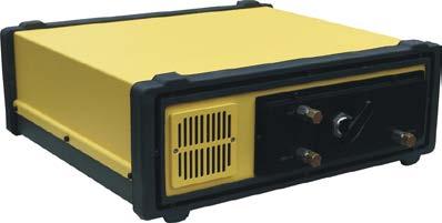
27 4.4 Gas Fittings As seen in Figure 10, all sample gas fittings in the DX-Series models are located on the back plate of the instrument. The sample gas connectors are: SAMPLE IN and OUT are Swagelok 6 mm and 8 mm or ¼ fittings in the DX4000 model, respectively. Outer diameter of the connecting tube is 6 mm, 8 mm, or ¼. The DX4015 model has a ZERO IN inlet in addition to the SAMPLE IN and OUT fittings. It is used for flushing the sample gas cell prior a background spectrum measurement. The analyser's purge gas fitting is located on the front of the enclosure. PURGE connector is a Swagelok fitting, as well. Only N 2 or dry and clean instrument air should be used to purge the analyser. DX4000 DX4015 Figure 10. Sample gas fittings of the DX4000 (upper) and DX4015 (lower) models. 27
28 When connecting Gasmet to the sampling system, please observe the following: 1 Connect the sample gas supply to the SAMPLE IN fitting (6 mm or ¼ ). The sample gas temperature must be the same as the sample cell temperature. Gasmet factory calibration is valid with original temperature settings only. 2 Connect the sample gas outlet to the OUT fitting (8 mm or ¼ ). Direct the gas to a suitable output line, for example to an exhaust gas channel, if available. Use short tubes. Throttling the sample gas outlet will increase the pressure in the sample cell. Uncontrolled pressure increase in the sample cell may result in large measuring errors. 4.5 On-board Sample Pump (only in the DX4015 model) The maximum sample gas temperature of the DX4015 model is 50 C. As the temperature is rather low, sampling system can be relatively simple. The DX4015 model is equipped with an on-board sample pump package, which has a neoprene diaphragm pump. Power supply is 12 VDC, maximum pressure 1.0 bar, and maximum flow is 2.8 l/min. 4.6 Power Connection Power Supply The required mains input is VAC, Hz. Hold-up time of Gasmet is 20 ms from loss of AC input. Use an uninterruptible power supply (UPS) if the electric power is subject to major disturbances or power failures. If no mains (AC electrical power supply) input is available, the DX4015 model can be operated with an optional 12 VDC power. Connect the power cable to Gasmet power supply unit that is equipped with standard CEE-22 plug. Never connect Gasmet to a mains (AC electrical power) supply that has no protective ground Fuses If you have to replace fuses, you may only use those that correspond exactly to specified values (3.15 AT, physical size 5 x 20 mm). Before checking the fuses, switch the power off. Fuses are located behind the IEC (International Electrotechnical Commission) power inlet unit (see Figure 11). Please see the Service Manual how to replace the fuses. 4.7 Signal Connections When you connect the Gasmet DX-Series to the sampling system, please use shielded cables only. Otherwise, the specified electromagnetic interference protection will be compromised. 28

29 4.7.1 Optional Analogue Output Signals Analogue output signals are available, if the computer used to operate DX-Series can be equipped with analogue output boards. Refer to their respective instruction manuals and Calcmet User's Guide and Reference Manual on how to use analogue outputs RS232 Interface RS232 interface is used for communication between the DX-Series and the external computer. For parameter settings, please refer Calcmet User's Guide and Reference Manual. Figure 11. Gasmet DX-Series connector unit. 29
30 5 START-UP Before you start to operate with Gasmet FTIR gas analyser, read this Manual and Calcmet for Windows User's Guide and Reference Manual carefully and thoroughly. If you do not understand something or you are unsure what to do, please contact the nearest distributor or Gasmet Technologies Oy main office. 5.1 Connections Make sure that all gas connections, power cable, and serial cable are connected correctly. Connect the serial cable to the external computer. Open the external computer and install the Calcmet software. 5.2 Installing Software Before installing Calcmet, installing of HASP drivers is necessary regardless of the fact that no HASP license key is required to run Calcmet in Standard mode. Next, to install Calcmet to your PC, run the Calcmet.msi installer package from your Calcmet software CD. You may optionally also create the following folders to your hard disk, although they are created during the install or when the directory is first required once the software is running: C:\CalcmetLibrary\ C:\CalcmetDemoLib\ C:\CalcmetSamples\ C:\CalcmetResults\ C:\CalcmetBackgrounds\ C:\CalcmetLog\ (recommended folder for reference spectra) (recommended folder for demo libraries) (recommended folder for sample spectra and residuals) (recommended folder for analysis results) (recommended folder for background spectra) (recommended folder for log files) After the setup procedure, you should have the following files in the C:\Program Files\Gasmet Technologies\Calcmet\ directory: Calcmet.exe DLPORTIO.dll PCI-Dask.dll ADAMTCP.dll hasp_windows_82882.dll TcAdsDll.dll Calcmet.MET MEASURINGTIMES.MES CalibrationInfo.dat CALCMET.BKG Version history.txt The executable main program file Application extension file Application extension file Application extension file Application extension file Application extension file Preset analysis method definitions Preset measuring timing definitions Latest calibration information (example) Latest background (example) Version information text file Once the files have been installed, it will still be necessary to set the reference spectrum libraries (calibrations), and other settings to make the measurements and analysis. Refer to the later chapters of this manual for description on setting all the analysis and measuring parameters. 30
31 The installation also includes the default library, three demo libraries tailored for different applications and some sample spectra. These are for demonstration and training purposes only and should not be used for analyzing any real measurements. All the demo library files can be found in C:\CalcmetDemoLib\ and the reference spectra for the demo libraries are situated in respective sub folders under the same path. The folder C:\CalcmetDemoLib\DemoSamples\ contains the demo sample spectra Installing Calibration Files Optionally there can be calibrations supplied with the analyser. To use the calibrations, it is necessary to copy the calibrations (reference spectra) and analysis settings to a specific location to make use of them. The default directory for calibration files (*.REF) is C:\CalcmetLibrary\. This is where the reference spectra from the install disk or CD should be copied. In addition to the reference spectra, there may be predefined analysis settings (*.LIB). After installing the software, these optional files need to the copied to the library directory, which is usually C:\CalcmetLibrary\. Once these analysis library settings have been copied to the program directory, it is possible to make use of them by selecting the application library in [OPTIONS] [APPLICATION] within the Calcmet program. If the reference spectrum files (*.REF) and library files (*.LIB) were copied from a CD, it may be that the files are write protected. To make later any changes to settings, it will be necessary to inactivate write protection from these files. This can be done by opening the file properties of all these files, and unchecking the Read-Only option Installing Optional Expansion Cards If you need to use optional relay cards, analogue input, or output cards with Windows XP, it is necessary to install drivers for these expansion cards. This additional procedure is not necessary if you do not have any of the optional expansion cards installed on your PC. The following setup packages are essential to using the optional expansion cards. Please use the appropriate setup program(s) to install the required driver(s) from the card manufacturer CD(s) or the Calcmet software CD. Alternately, please contact your distributor to obtain the correct setup package. Expansion card used Old Gasmet PC with ISA relay cards Any ADLink PCI expansion card(s) ADAM5000/TCP Ethernet Beckhoff Ethernet PLC / IO Gasmet PC watchdog Setup package name port95nt.exe PCIS-DASK V4.14.zip eadamutility.exe tcat_2100_1328.exe v1.3_wdt_dio_lx800.rar 31
32 Please note that in most cases after installing the drivers, restarting of Windows might be necessary HASP Licensies and Keyes If you have been supplied with a HASP license key, the key is required to run the software in the correct operating mode. The software will only run in Standard mode without a key. The HASP key may be inserted at any time while the software is running or before it is launched. When the key is inserted for the first time, it may take a short period of time before the key is actually found. All currently available Calcmet software licenses to date: Standard no key required, no cost basic functionality Professional key required fast measurement mode (<1s) enabled all advanced features will be contained in future updates of this version free of further charge 4030Std key required measuring and expansion cards are not supported with DX4030 models 250 gas reference spectra library included 4030Pro As 4030Std, but with measuring and expansion cards supported Important notice: If the HASP key is damaged, either electrically or physically, do not throw it away unless you are prepared to pay the license fee again. By returning the key, you will be provided with a new key at the list price of a replacement key, but not at the price of a new license Uninstalling Calcmet Software There are two ways Calcmet can be correctly removed from your system. Failing to uninstall the software correctly in one of the following ways may prevent further installations of the software: - relaunching the installation package and choosing the Remove option - through the Windows Control Panel Add/Remove Programs 32

33 5.3 Switching the Analyser's Power On Prior to switching the analyser s power Check the power supply setting. The mains voltage must meet the specified values: 115 VAC or 230 VAC, Hz. Check the analyser s setting voltage! Make sure that sample-conditioning system is operationally ready, if applicable. All parts of the sampling system must be at the same temperature as the temperature in the sample cell and all dust particles must be filtered. Before the sample cell is at the target temperature, make sure that the sample cell is empty or filled with zero gas. Never let the sample gas to the cold sample cell. The power switch is located on the rear panel of the enclosure. Switch the power on. After switching the power on, the sample cell starts to heat to the target temperature. The heating process will take about minute to reach 180 C. 5.4 Operation Calcmet is the software for operating and controlling the Gasmet analyser system via RS232 serial line. Calcmet runs on an external PC compatible computer with Windows XP operating system. This chapter describes the typical procedures that the user is likely to carry out with the Calcmet program, for more information read the Calcmet for Windows User's Guide and Reference Manual Using the Calcmet Software The Calcmet analysis and controlling software resides on an external PC computer that is connected to the analyser with the proprietary Gasmet RS232 serial cable. Once the hardware is turned on, the Calcmet software on the external computer must be started. Run the program C:\Program Files\Gasmet Technologies\Calcmet\Calcmet.exe to start the application. The installation package should also have created a desktop and program menu shortcut under Start Programs Gasmet Technologies for this purpose. The software and PC may also be started before the analyser, but you should not try to start any measuring function before the analyser is connected, turned on, and stabilized. When the software is starting up, there will be a Window displaying STARTING CALCMET - Please wait. The start-up takes normally a few seconds, but the exact start-up time depends on the processing power of the PC and the size of the library currently in use. When the software is started for the first time after installation, a dialogue appears that asks for some system information (Figure 12). If the PC is connected to the Gasmet analyser, or if you are planning to use any optional expansion cards with the software, it is important to set these parameters correctly. The explanation of the parameters is in 33
![Table 1. Figure 12. 'Welcome to Calcmet' dialogue. If you need to change the parameters later, this can be done from the Calcmet menu [Tools] [Configuration ].](/docs-images/95/125750876/images/34-0.jpg "The same Welcome to Calcmet interface will appear, but the window title will be changed to Configuration settings. Please see the Calcmet for Windows User's Guide for details.")
34 Table 1. Figure 12. 'Welcome to Calcmet' dialogue. If you need to change the parameters later, this can be done from the Calcmet menu [Tools] [Configuration ]. The same Welcome to Calcmet interface will appear, but the window title will be changed to Configuration settings. Please see the Calcmet for Windows User's Guide for details. Parameter Options Action SERIAL NUMBER SERIAL PORT Calcmet automatically detects the available ports. Assumes that COM1 always exists. Serial number of the Gasmet analyser, the field is disabled if the serial number differs from zero Serial port on the PC where Gasmet analyser is or will be connected. Please note that the actual interface may be RS232, RS422 or RS485. BAUD RATE 9600 / / / / / / Baud rate for communicating with Gasmet. This value must match the analyser hardware setting. Most new analysers use baud rate. DATA FORMAT 16 bit / 24 bit This setting depends on the analyzer EPROM. MODE Standard / Fast / Other Fast mode is only available with Professional license, others depending on key inserted. Table 1. Welcome to Calcmet Analyzer parameters. 34

35 If you are planning to make measurements with the software and if the analyser has been shut down, it is recommended to wait some time for the analyser to stabilize before starting the actual measurements. You should wait at least For the sample cell to reach the set, stable temperature One (1) hour for temperature stabilization in the analyser If the analyser has been stored in a low temperature condition, the temperature stabilization can take longer than an hour. For more information on analyser hardware, refer to the instructions manual of the analyser Setting the Measurement Times The measuring times are set on the Measuring Times dialogue (Figure 13). Table 2 lists the Measuring Times dialogue settings. If there are no external valves or pump connected for automatic, continuous operation, only the SamplingTime and Measuring Interval need to be set. For multi point sampling, the measuring time list can contain any number of entries. Once the end of the list is reached during continuous measuring the cycle will restart from the first position on the list. Figure 13. 'Options / Measuring Times' dialogue. 35
36 Parameters Options Action Line number 0-16 Line number zero is used for single point sampling. For multi point sampling line numbers start from one. Flush Time (s) s Sample cell flush time in seconds. After zero calibration, the analyser waits this time before starting new sample measurement. Pump Time (s) 10 s / 30 s / 1 min / 3 min / 5 min / continuous or any desired value between s. Sampling time (s) 1 s / 5 s / 20 s / 1 min / 3 min / 5 min or any desired value between s. Pump operating time in seconds. Before measuring the sample, the sample pump will be running this time. Sample measurement time. The respective zero calibration measuring times are set automatically to 10 s / 30 s / 1 min / 3 min / 5 min / 10 min. For multi point sampling the zero calibration time is calculated from the longest sampling time in the list. Measuring Interval (s) Number of samples s Time in seconds between starting successive sample measurements when using Continuous measuring. If this value is less than Sampling time, it has no effect. 1 - Number of samples to measure on the same sample line, before moving to the next item on the measuring times list. Table 2. Commands for setting measuring times Zero Calibration It is first necessary to measure the background spectrum (zero calibration) for subsequent sample spectrum measurements. Before making the zero calibration, wait until the instrument has reached a steady condition. The sample cell temperature and interferometer temperatures must be stable. For the zero calibration measurement, the sample cell must be filled with zero gas like pure N 2 or O 2. Make sure there is no sample gas or other unwanted substances in the sample cell. The sample cell must be flushed with the zero gas a few minutes before initiating the background measurement. Please remember to use a heated line that is in the same temperature as the sample cell when flushing in the zero gas. To start the background measurement, open the Measure menu and choose the command Background Table 3. If it is necessary to change the measuring time for the zero calibration, first run a single measurement from one of the toolbar buttons. The zero calibration time is adjusted automatically to be suitable for the last single measurement. For continuous measuring, the background time is calculated from the largest sample measuring time in the Measuring times dialogue. 36
37 Action 1 Run a single measurement with the desired time from the toolbar, the background time is adjusted accordingly. Commands [OPTIONS] [MEASURING TIMES] Set the sample measuring time(s). The zero calibration time in continous measuring will be set automatically according to the largest sample measuring time in the measuring times list. <OK> 2 Perform the measurement. [MEASURE] [BACKGROUND] Table 3. Zero calibration measurement commands. A typical background spectrum is presented in Figure 14. The background graph does not present absorbance nor transmittance spectrum. The background is a single beam spectrum that shows the actual absolute intensity of infrared radiation that is transmitted through the zero gas filled sample cell. The background spectrum is used as the zero level, to which the actual sample measurements are later compared. This zero level is needed to calculate the absorbance or transmittance values of the sample. Figure 14. A typical background spectrum. In normal conditions, the shape of the background spectrum should be near to that shown in Figure 14. The absorbance peak at 2350 cm -1 results from CO 2 that is typically present in the optical path. The smaller peaks in the range of cm -1 result from humidity that is also normally present in the optical path. 37
38 5.4.4 Measuring the Sample Spectrum Single Measurement When the zero calibration is completed, the analyser is ready for the sample measurements. Open the Measure menu and choose the command Single to make a single measurement of the sample (Table 4). The sample will be measured according to the last single measurement made. If the Analyse option is on, the sample will be automatically analysed, too. To measure the sample spectrum without automatic analysis, uncheck the parameter Analyse in the settings menu. Action Commands 1 Set the sample measuring time. [OPTIONS] [MEASURING TIMES] Set the sample measuring time, if necessary. If you change the time longer, the background should be remeasured. <OK> 2 Measure the sample. [MEASURE] [SINGLE] Table 4. Single measurement commands Continuous Measurement To make continuous measurements, open the Measure menu and choose the command Continuous. The sample will be measured continuously until <Cancel> button is pressed. The results will be shown and updated on the screen continuously after each measurement. If the result autosaving option is set on, the results of each measurement will be saved to the disk. In addition to the sample, the background can be measured automatically at time intervals specified by the user. Furthermore, time intervals can be specified for purging the sample cell. If it is necessary to change these measuring parameters for the continuous sample measurement, open the menu Measure and choose the command Measuring times (Table 5). Set the value for Measurement time (s) to indicate the appropriate measurement time. 38
39 Action 1 Set the measuring parameters: measuring time, measurement interval, and sample cell flush time. Commands [OPTIONS] [MEASURING TIMES] Set the measuring parameters, if necessary. If you change the measuring time longer, the background should be re-measured. <OK> 2 Start continuous measuring. [MEASURE] [CONTINUOUS] 3 Stop continuous measuring. <Cancel> Table 5. Continuous measurement commands Checking the Hardware It is recommended to write regularly down the interferogram centre and the maximum peak height from the Hardware Status display (Table 6). This could be done, for example, once a day right after the zero calibration. If the values have changed noticeably, it may indicate that some parts need cleaning or calibration. For example, decreasing amplitude of the interferogram peak height may indicate that the optics of the sample cell are getting dirty. Before running this command, the temperatures of the analyser should be fully stabilized. If some readings appear to be abnormal, try resetting the whole analyser before any other maintenance operation. Action Commands 1 View hardware information [VIEW] [HARDWARE STATUS] 2 Exit display <OK> Table 6. Commands for checking hardware status Analyzing the Sample Spectrum To analyze correctly the sample, a good quality background must be measured, an analysis library specified and set, and the sample itself measured. When all these three components are first done correctly, reliable analysis results can be obtained. For more information, please consult the Calcmet User's Guide and Reference Manual. 5.5 Sample Calcmet Session Suppose that the reference spectrum library is already specified, but there is no background spectrum, or sample. To measure and analyze a sample, proceed as follows: 39
40 5.4.1 Step 1: Select the Components That Will Be Analyzed In the analysis library, you have to include all those components in the analysis that are present in the sample gas mixture. If there is a significant amount of some substance in the sample that is not listed in the library, the results of the analysis are likely to be incorrect. To include or exclude components from the analysis, open the Analysis Settings dialogue in the Edit menu. To toggle the analysis of any component ON or OFF, click the check box next to the component name. The components that are currently included in the analysis are shown with a tick mark Step 2: Measure the Background When measuring the background, the sample cell must be filled with a zero gas. Zero gas must not absorb infrared radiation. A typical zero gas is nitrogen (N 2 ). Be sure there are no other substances in the sample cell at the time of background measurement. In addition, make sure Gasmet is fully stabilized. The power must have been turned on at least 30 minutes earlier or longer if the temperatures of the system have not yet stabilized. For precise measurements, let the system stabilize longer. Every time any environmental conditions change, it is recommended to re-measure the background. Even if there has been no noticeable change, it is good practice to re-measure the background every now and then, at least every 24 hours. To start measuring the background, open the Measure menu and choose the command Background. The time of the background measurement will be automatically adjusted suitable with respect to the actual sample measuring time. If you change the sample measuring time longer, measure the background again. When the background measurement has finished, a graph displaying the background spectrum will be shown on the screen Step 3: Measure and Analyze the Sample To change the measuring time for the sample measurement, open the Options menu and choose the command Measuring Times. Set the value for Sampling Time (s) to indicate the appropriate measurement time. The measurement time can be, for example, 20 seconds or 1 minute. The smaller the concentrations measured are, the longer the measurement times should be. Next, open the Measure menu and choose the command Single to make a single measurement of the sample. The analysis results are shown on the screen, if the Analyze option in the Options menu is checked Step 4: Verify the Results A good indication of how good the analysis was and how good the results are is the residual graph. Open the View menu and choose the command Residual. This graph shows the residual between the measured sample spectrum and the model used in the analysis for the selected component. If the residual does not show any clear peaks but 40
41 noise, and the peak heights are close to zero everywhere, the analysis was successful. In successful measurements, the residual peaks must be below 0.01 in the absorbance scale, and for precise measurements even better. If there are any clear spectral structures, or the base line is tilted, try to include some possibly missing components to the analysis and analyze the sample again to get better results. Sometimes it also may be necessary to measure the background again to get better results. Shortcut to display the residual together with the respective reference spectrum is to double-click the maximum residual number of the component in the result display. The maximum residual number is displayed in the last column of the result display. 41
42 6 MAINTENANCE 6.1 Safety Precautions Improper handling of any components inside Gasmet may damage the equipment. Thus, adjustment of any components inside Gasmet avoids warranty. Any service operations that require opening the case of Gasmet should be performed only by Gasmet Technologies Oy qualified technician. The case should be opened only when Gasmet is turned off, and the power cable and the gas lines disconnected. The user should pay attention to the following points: 1 Every time after the measurements and before turning off the power of Gasmet, the sample cell should be carefully flushed with nitrogen gas or dry instrument air. Sample cell should be closed with caps if the sample lines are disconnected from the gas cell. If corrosive gases remain in the sample cell when the power has been switched off, the optics inside the sample cell will be damaged. Measuring strongly acid or caustic gases may shorten the lifetime of the sample cell. 2 If the sample gas contains solid particles, it should be filtered before introducing it into the sample cell. If it is not filtered, dirt will accumulate in the sample cell and lower the quality of the measurements. Any liquid droplets or aerosols inside the gas cell may destroy sample cell mirrors or optical windows. 3 After power has been switched off for a longer period or the unit is used in extremely humid ambient conditions, it is recommended to purge the spectrometer and detector with dry nitrogen gas to avoid ice formation on the detector window. 4 The pressure and temperature of the sample gas should always be kept as stable as possible. However, the gas entering the sample cell should already be as close as possible to the sample cell temperature. 5 Intensive shocks may damage the analyser. Be always very careful when you move or transport the instrument. 6 Use a soft cloth to wipe off the dirt on the case. The case of Gasmet is not waterproof. Do not apply running water when cleaning the case. Do not use strong detergents or acetone. If the instrument is used in dusty conditions, it is recommended to vacuum clean the dust filters (and replace if necessary) at least once a month. The filters are located on the front and back panels of the instrument. 6.2 Maintenance Plan Table 7 presents a rough maintenance plan. The maintenance required depends strongly on the application. The maintenance work procedures are described in this manual. Operations that are more detailed are described in the Service Manual. 42
43 Maintenance interval Maintenance work 1 month Visual inspection and sample conditioning system inspection (according to the instructions given by manufacturer(s) of the system components). Vacuum clean the dust filters months Water calibration (performed by trained service personnel). Approximately 12 months Annual service: analyser inspection, cleaning, and tuning (performed by trained service personnel). 2 3 years IR source replacement (performed by trained service personnel). 3 5 years Laser source replacement (performed by trained service personnel). Table 7. Maintenance plan. In principle, Gasmet requires no calibration except zero calibration after the original factory set-up. Water vapour calibration is however an exception to the rule. It is highly recommended that its calibration is performed at least 1-2 times a year especially after a relocation of the analyser or if any optical parts have been replaced or aligned. 6.3 Visual Inspection When you make the visual inspection check that: there exist enough zero gas for automatic background measurements (with automated sampling system) sampling system, sample lines and gas connectors are in good condition sample cell temperature is correct sample line temperatures are correct sample gas flow is correct purge gas flow is correct 6.4 Sample Cell Inspection The sample cell inspection can be made for all types of sample cells. Only a qualified technician may perform sample cell inspection. Sample cell inspection is described in detail in the Service Manual. The operation includes following procedures: sample cell optical window check sample cell mirror inspection water calibration operational test 43
44 6.5 Replacement of Optoelectronic Components Only trained service personnel may perform replacement of any of the optoelectronic components. Expected lifetime of the detector is five (5) years and laser tube three (3) years. However, to avoid any unexpected faults it is recommended that infrared light source is replaced once in every 2-3 years laser tube and its power source is replaced once in 3-5 years detector is replaced if necessary 44
45 7 ANALYSER INSPECTION The analyser must be inspected within 30 days from the date of delivery, to ensure that the warranty is valid in full. Please check the following points and fill the Gasmet FTIR Gas Analyser Inspection Sheet on the next page. If you noticed that something is missing or the analyser is damaged during transportation, please contact the nearest distributor or Gasmet Technologies Oy. Before you make this inspection, it is recommended to read Calcmet User's Guide and Reference Manual and Gasmet Instruction & Operating Manual, especially Chapter 5 Start-up. 1. Check the condition of the shipping box. 2. Check that no items listed in Chapter Contents of the Gasmet Package are missing. 3. Check visually that the analyser's enclosure is undamaged. 4. Connect serial and power cable. 5. Install the Calcmet program to an external PC. 6. Switch the analyser s power on. 7. Wait before the analyser has reached the stable operating conditions. Then check the Hardware Status and write down all the parameters in the inspection sheet. 8. After checking Hardware Status, measure a single sample spectrum with pure nitrogen and use 20 seconds measuring time. Save the sample spectrum. Print also the sample spectrum on a paper. The sample spectrum includes a lot of information that can be used for troubleshooting purposes. It is important to use the factorymeasured background in this test. Do not measure a new background! 9. Send copy of the filled Gasmet FTIR Gas Analyser Inspection Sheet to Gasmet Technologies Oy by fax, mail, or . Please see the contact information at the bottom of the page or on the last page of this manual. 45
46 7.1 Gasmet FTIR Gas Analyser Inspection Sheet Gasmet model: Date of delivery: Representative Serial number: company: 1. Condition of the shipping box Correct Remarks 2. Contents of the Gasmet package Correct Remarks 3. Visual inspection Correct Remarks 4. Software Software installed from the software DVD Software runs correctly Factory measured background file Calcmet.bkg moved from the software DVD to the external computer 4. Hardware Status parameters Time measured: Interferogram Centre: Status: Interferometer Temp.: Source Intensity: Sample Cell Temp.: Interferogram Height: Software version: 5. Sample spectrum successfully measured (20 s) with pure nitrogen gas using factory measured background and saved. Yes No Please attach the sample spectrum to this form. Name: Position: Date: Send a copy of this filled Gasmet FTIR Gas Analyser Inspection Sheet to Gasmet Technologies Oy by fax, mail, or electronic mail. See the contact information on the bottom of the page. 46
47 APPENDIX A: VOCABULARY Absorbance Beam splitter Beer's law Detector Fourier transform (FT) A measure of the amount of infrared radiation absorbed by a sample gas as a function of frequency. A component in the interferometer that reflects half of the infrared radiation and transmits the other half. The law stating that the absorbance is linearly proportional to the concentration of the gas (see page 13). The component that measures the intensity of the infrared radiation and converts this value into electrical signal. The mathematical algorithm to get spectral data out of the interferogram. The algorithm transforms the intensity as a function of time values to intensity as a function of wavelength. Infrared (IR) Electromagnetic radiation that has wavelengths ranging from 0.75 µm to 1000 µm ( cm -1 ). Interferogram Interferometer Noise Reference spectrum Resolution Signal-to-noise ratio (SNR) Spectrum Transmittance Wavelength Wave number The measured intensity as a function of optical path length difference The device that produces interference signal of the infrared radiation. Detected signals that do not come from the sources that we actually want to measure. A spectrum that is used as a known reference when determining the concentrations of unknown gas components. The degree to which different frequencies can be distinguished from each other. The ratio of the amplitude of the actual measured signal to the amplitude of the noise at the same point. A graph that shows the transmission of the infrared radiation through the gas as a function of wavelength The ratio of the infrared radiation transmitted through the sample gas to the amount of the infrared radiation entering the sample gas. Another form of expressing the frequency of the infrared radiation: the distance between two peaks in the oscillation. Number of wavelengths in a centimetre. For example, if the wavelength is 10 µm, the corresponding wave number is 1000 cm
 Ltd.")
48 APPENDIX B: GASMET SALES AND SUPPORT OFFICES Manufacturer Gasmet Technologies Oy Pulttitie Helsinki FINLAND Tel. (+358) Fax (+358) contact@gasmet.fi Subsidiary in North America Gasmet Technologies Inc. 956A The Queensway Toronto, Ontario, M8Z 1P5 CANADA Tel: sales@gasmet.com Subsidiary in Asia Gasmet Technologies (Asia) Ltd. Unit 1, 7/F, Fook Hong Industrial Building, No. 19 Sheung Yuet Road, Kowloon Bay Kowloon HONG KONG Tel: Fax: sales@gasmet.com.hk Distributors Please see our website at 48
FTIR GAS ANALYSIS WHITE PAPER INTRODUCTION TYPICAL APPLICATIONS
 WHITE PAPER W FTIR GAS ANALYSIS INTRODUCTION FTIR (Fourier Transform InfraRed) spectroscopy is the most popular analytical technology for industrial applications requiring the continuous measurement of
DM70 Hand-Held Dewpoint Meter for Spot-Checking Applications
 DM70 Hand-Held Dewpoint Meter for Spot-Checking Applications The Vaisala DRYCAP Hand-Held Dewpoint Meter DM70 offers accurate and fast measurement for industrial dewpoint applications, such as compressed
473-SHX Dew Point Mirror
 Humidity and Temperature Reference Hygrometer For Temperature up to 125 C Precise and stable chilled mirror dew point mirror technology High temperature optical components High temperature sample fan Cable
UV3000. Accurate, precise, and portable ambient gas point analyzer
 UV3000 Accurate, precise, and portable ambient gas point analyzer The Cerex UV3000 is a multifunction analyzer designed to detect part per billion (ppb) to percent level concentrations of multiple gases
Safety Precautions WARNING If critical situations that could lead to user s death or serious injury is assumed by mishandling of the product.
 Safety Precautions Observe the following notices to ensure personal safety or to prevent accidents. To ensure that you use this product correctly, read this User s Manual thoroughly before use. Make sure
Introduction to Fourier Transform Infrared Spectroscopy
 molecular spectroscopy Introduction to Fourier Transform Infrared Spectroscopy Part of Thermo Fisher Scientific Introduction What is FT-IR? FT-IR stands for Fourier Transform InfraRed, the preferred method
DM70. Hand-held Dewpoint Meter. Truly Fast Response - Superior Long-term Stability
 DM70 Hand-held Dewpoint Meter Truly Fast Response - Superior Long-term Stability DM70 - When Dry Air Is Important The Vaisala DM70 Hand-held Dewpoint Meter offers stable and fast measurement for industrial
Operating Instructions for Digital Manometer. Model: MAN-SD
 Operating Instructions for Digital Manometer Model: MAN-SD 1. Contents 1. Contents...2 2. Note...3 3. Instrument Inspection...3 4. Regulation Use...4 5. Operating Principle...4 6. Mechanical Connection...5
Introduction to Fourier Transform Infrared Spectroscopy
 Introduction to Fourier Transform Infrared Spectroscopy Introduction What is FTIR? FTIR stands for Fourier transform infrared, the preferred method of infrared spectroscopy. In infrared spectroscopy, IR
STATIC GAS MONITOR Type SGM/DEW Revision A of 20 aprile 2016
 APPLICATIONS Moisture monitoring of air or gas (SF6) Suitable for indoor or outdoor Industrial, medical or aerospace fields HIGHLIGHTS High voltage circuit breakers commonly used for distribution and transmission
Installation guide 862 MIT / MIR
 Installation guide 862 MIT / MIR in combination with: 864 MTT or 863 MRT or (dual) spot element November 2005 Part no. 4416.232_Rev3 Enraf BV PO Box 812 2600 AV Delft Netherlands Tel. : +31 15 2701 100
ISOCON-6. 24V AC or DC POWERED ISOLATING SIGNAL CONVERTER
 ISOCON-6 24V AC or DC POWERED ISOLATING SIGNAL CONVERTER Whilst every effort has been taken to ensure the accuracy of this document, we accept no responsibility for damage, injury, loss or expense resulting
473 Dew Point Hygrometer
 High Performance Chilled Mirror Hygrometer With Cable Mounted Measuring Heads Highly precise chilled mirror dew point technology Cable mounted dew point and temperature measurement Aspirated and direct
Orbit Support Pack for Excel. user manual
 Orbit Support Pack for Excel user manual Information in this document is subject to change without notice. Companies, names and data used in examples herein are fictitious unless noted otherwise. No part
DM70 Hand-Held Dewpoint Meter for Spot-Checking Applications
 DM70 Hand-Held Dewpoint Meter for Spot-Checking Applications The Vaisala DRYCAP Hand-Held Dewpoint Meter DM70 offers accurate and fast measurement for industrial dewpoint applications, such as compressed
Creating Empirical Calibrations
 030.0023.01.0 Spreadsheet Manual Save Date: December 1, 2010 Table of Contents 1. Overview... 3 2. Enable S1 Calibration Macro... 4 3. Getting Ready... 4 4. Measuring the New Sample... 5 5. Adding New
SkyScan EWS-PRO - Manual -
 INTRODUCTION SkyScan EWS-PRO - Manual - EWS-Pro gives you advance weather warning technology you can use at home, indoors or out, and take wherever you go, for any kind of outdoor activity. Your EWS-Pro
Fog Monitor 100 (FM 100) Extinction Module. Operator Manual
 Extinction Module. Operator Manual") Particle Analysis and Display System (PADS): Fog Monitor 100 (FM 100) Extinction Module Operator Manual DOC-0217 Rev A-1 PADS 2.7.3, FM 100 Extinction Module 2.7.0 5710 Flatiron Parkway, Unit B Boulder,
Particle Analysis and Display System (PADS): Fog Monitor 100 (FM 100) Extinction Module Operator Manual DOC-0217 Rev A-1 PADS 2.7.3, FM 100 Extinction Module 2.7.0 5710 Flatiron Parkway, Unit B Boulder,
Spectrometer User s Guide
 Spectrometer User s Guide (Order Codes: V-SPEC, SPRT-VIS, SP-VIS, SP-UV-VIS, ESRT-VIS) The spectrometer is a portable light spectrophotometer, combining a spectrometer and a light source/cuvette holder.
O P E R A T I N G M A N U A L
 OPERATING MANUAL WeatherJack OPERATING MANUAL 1-800-645-1061 The baud rate is 2400 ( 8 bits, 1 stop bit, no parity. Flow control = none) To make sure the unit is on line, send an X. the machine will respond
ED 701 General Industry Pressure Transmitter
 ED 701 General Industry Pressure Transmitter Standard industrial process connections Complete range of electrical connections 4... 20 ma and Voltage outputs Accuracy: 0.1%, 0.2% and 0.4% FS Quick response
AM 500A 500 WATT AM 1A 1 KILOWATT AM BROADCAST TRANSMITTERS. October, 1999 IM No
 AM 500A 500 WATT AM 1A 1 KILOWATT AM BROADCAST TRANSMITTERS October, 1999 IM No. 597 1112 EQUIPMENT LOST OR DAMAGED IN TRANSIT. When delivering the equipment to you, the truck driver or carrier s agent
Request Ensure that this Instruction Manual is delivered to the end users and the maintenance manager.
 Request Ensure that this Instruction Manual is delivered to the end users and the maintenance manager. 1 -C - Safety section - This Safety section should be read before starting any work on the relay.
473 Dew Point Hygrometer
 gh Performance Chilled Hygrometer With Cable Mounted Measuring Heads ghly precise chilled mirror dew point technology Cable mounted dew point and temperature measurement Aspirated and direct insertion
WeatherHub2 Quick Start Guide
 WeatherHub2 Quick Start Guide Table of Contents 1 Introduction... 1 2 Packing List... 1 3 Connections... 1 4 IP Addressing... 2 5 Browser Access... 3 6 System Info... 3 7 Weather Station Settings... 4
BOXA-II ON-STREAM X-RAY FLUORESCENCE ANALYZER. Technical Description Version 2 BGRIMM AUTOMATION
 BOXA-II ON-STREAM X-RAY FLUORESCENCE ANALYZER Technical Description Version 2 BGRIMM AUTOMATION, South 4th Ring Road West, Beijing, China TEL: +86(10)59069762 Fax: +86(10)68360101 Contents BGRIMM AUTOMATION
Agilent Cary 630 FTIR sample interfaces combining high performance and versatility
 Agilent Cary 630 FTIR sample interfaces combining high performance and versatility Technical Overview Introduction The Agilent Cary 630 is a robust, easy to use, superior performing FTIR in a compact package.
M2 SERIES THERMOSTATS 0 F to 240 F, Narrow Differential, Hermetically Sealed ½
 M2 SERIES THERMOSTATS 0 F to 240 F, Narrow Differential, Hermetically Sealed ½ Introduction The Klixon M2 thermostat is constructed with a snap acting bimetal disc that serves as the actuating element.
FLT5A FLT5A. abc. abc. Thermometer User Guide. Thermometer User Guide. Internet:
 abc instruments international FLT5A Thermometer Land Instruments International Dronfield, S18 1DJ England Telephone: (1246) 417691 Facsimile: (1246) 41585 Email: infrared.sales@landinst.com Internet: www.landinst.com
Fourier Transform Infrared Spectroscopy (Perkin Elmer - Spectrum One)
") Fourier Transform Infrared Spectroscopy (Perkin Elmer - Spectrum One) This operating procedure intends to provide guidance for transmission/absorbance measurements with the FTIR. For additional modes of
Fourier Transform Infrared Spectroscopy (Perkin Elmer - Spectrum One) This operating procedure intends to provide guidance for transmission/absorbance measurements with the FTIR. For additional modes of
1/5 Specifications Hidex 300 SLL automatic TDCR liquid scintillation counter
 1/5 Specification Hidex 300 SL-SLL 100-240V AC and 24 V DC. Features Model (425-020) Super Low Level (SLL) Automatic TDCR Liquid Scintillation Counter with Guard Detector and Low Level PMTs General Description
User Manual VX4750 Function Generator Module
 User Manual VX4750 Function Generator Module 070-9151-05 This document applies for firmware version 2.60 and above. Copyright Tektronix, Inc. All rights reserved. Tektronix products are covered by U.S.
Turbine Meter TRZ 03 PRODUCT INFORMATION. Reliable Measurement of Gas
 Turbine Meter TRZ 0 PRODUCT INFORMATION Reliable Measurement of Gas TURBINE METER TRZ 0 Method of operation, Construction Method of operation The TRZ 0 turbine meter is a flow meter suitable for gas measurement
Vaisala DRYCAP Hand-Held Dewpoint Meter DM70. Fast Response - Low Maintenance
 Vaisala DRYCAP Hand-Held Dewpoint Meter DM70 Fast Response - Low Maintenance DM70 Hand-Held Dewpoint Meter for Spot-Checking Applications The Vaisala DRYCAP Hand- Held Dewpoint Meter DM70 offers accurate
Introduction to Blackbody Sources
 Introduction to s This section contains dedicated blackbody sources for low uncertainty calibration of infrared thermometers. A range of portable primary blackbody sources combine high emissivity with
Mercury Stack Monitor SM-4
 Member of the envea Group Mercury Stack Monitor SM-4 Automatic continuous emission monitor (CEM) for mercury Continuous operation Sample dilution directly at stack - works with virtually any sample matrix
Agilent G2350A Atomic Emission Detector (AED)
") Agilent G0A Atomic Emission Detector (AED) Specifications Elements Specifications Wavelength Minimum Detectable Selectivity Dynamic Measurement Group Element(s) (nm) Level (pg/sec) Over Carbon Range Compound
Agilent G0A Atomic Emission Detector (AED) Specifications Elements Specifications Wavelength Minimum Detectable Selectivity Dynamic Measurement Group Element(s) (nm) Level (pg/sec) Over Carbon Range Compound
INSTRUCTION MANUAL Milwaukee Refractometer MA881 Refractometer for Invert Sugar Measurements
 www.milwaukeeinst.com INSTRUCTION MANUAL Milwaukee Refractometer MA881 Refractometer for Invert Sugar Measurements www.milwaukeeinst.com 1 Instruction Manual MA881 Refractometer for Invert Sugar Measurements
Introduction to FT-IR Spectroscopy
 Introduction to FT-IR Spectroscopy An FT-IR Spectrometer is an instrument which acquires broadband NIR to FIR spectra. Unlike a dispersive instrument, i.e. grating monochromator or spectrograph, an FT-IR
ONYX -MCE MULTI-CHANNEL OPTICAL FIBER PYROMETERS WITH ACTIVE EMISSIVITY COMPENSATION PRECISION TEMPERATURE MEASUREMENT FOR DEMANDING INDUSTRIAL
 ONYX -MCE MULTI-CHANNEL OPTICAL FIBER PYROMETERS WITH ACTIVE EMISSIVITY COMPENSATION PRECISION TEMPERATURE MEASUREMENT FOR DEMANDING INDUSTRIAL APPLICATIONS Accurate, repeatable, and reliable temperature
DAY LABORATORY EXERCISE: SPECTROSCOPY
 AS101 - Day Laboratory: Spectroscopy Page 1 DAY LABORATORY EXERCISE: SPECTROSCOPY Goals: To see light dispersed into its constituent colors To study how temperature, light intensity, and light color are
Extrel is widely respected for the quality of mass spectrometer systems that are
 Extrel is widely respected for the quality of mass spectrometer systems that are available to the world's top research scientists. In response to increasing requests for complete turn-key systems built
566/568. Infrared Thermometers. Getting Started
 566/568 Infrared Thermometers Getting Started PN 2812159 August 2007 Rev. 2, 4/08 2007-2008 Fluke Corporation. All rights reserved. Printed in China. Product specifications are subject to change without
Skin Damage Visualizer TiVi60 User Manual
 Skin Damage Visualizer TiVi60 User Manual PIONEERS IN TISSUE VIABILITY IMAGING User Manual 3.2 Version 3.2 October 2013 Dear Valued Customer! TiVi60 Skin Damage Visualizer Welcome to the WheelsBridge Skin
Dielectric Analysis of Solid Insulations
 using Dielectric Test Fixture 16451B from Keysight By Britta Pfeiffer 2018 by OMICRON Lab V2.0 Visit www.omicron-lab.com for more information. Contact support@omicron-lab.com for technical support. Page
Ocean Optics Red Tide UV-VIS Spectrometer (Order Code: SPRT-UV-VIS)
") Ocean Optics Red Tide UV-VIS Spectrometer (Order Code: SPRT-UV-VIS) The UV-VIS spectrometer is a portable ultraviolet light and visible light spectrophotometer, combining a spectrometer and a light source/cuvette
Ocean Optics Red Tide UV-VIS Spectrometer (Order Code: SPRT-UV-VIS) The UV-VIS spectrometer is a portable ultraviolet light and visible light spectrophotometer, combining a spectrometer and a light source/cuvette
Detection of trace contamination on metal surfaces using the handheld Agilent 4100 ExoScan FTIR
 Detection of trace contamination on metal surfaces using the handheld Agilent 4100 ExoScan FTIR Ensuring ultimate cleanliness for maximum adhesion Application Note Author John Seelenbinder Agilent Technologies,
ABB MEASUREMENT & ANALYTICS DATA SHEET. PGC5000 Temperature programmed gas chromatograph
 ABB MEASUREMENT & ANALYTICS DATA SHEET PGC5000 Temperature programmed gas chromatograph 2 P G C 5 0 0 0 T E M P E R AT U R E P R O G R A M M E D D S/ P G C 5 0 0 0 T P - E N Measurement & Analytics The
Instruction Manual SEFRAM Thermal Camera
 Instruction Manual SEFRAM 9830 Thermal Camera EN Introduction The SEFRAM 9830 Thermal Camera (the Product) can display thermal gradient, temperature readings, map and measure the infrared energy radiated
ISSP User Guide CY3207ISSP. Revision C
 CY3207ISSP ISSP User Guide Revision C Cypress Semiconductor 198 Champion Court San Jose, CA 95134-1709 Phone (USA): 800.858.1810 Phone (Intnl): 408.943.2600 http://www.cypress.com Copyrights Copyrights
Request Ensure that this Instruction Manual is delivered to the end users and the maintenance manager.
 Request Ensure that this Instruction Manual is delivered to the end users and the maintenance manager. 1 -A - Introduction - Thank for your purchasing MITSUBISHI ELECTRIC MELPRO TM D Series Digital Protection
INSTRUCTION MANUAL. Laser Diode Sarcomere Length. Aurora Scientific Inc. 360 Industrial Parkway South, Unit 4 Aurora, Ontario, Canada L4G 3V7
 INSTRUCTION MANUAL Model 902A Laser Diode Sarcomere Length May 6, 2013, Revision 3 Copyright 2008-2013 Aurora Scientific Inc. Aurora Scientific Inc. 360 Industrial Parkway South, Unit 4 Aurora, Ontario,
XR Analog Clock - Manual Setting Model Troubleshooting Guide
 Primex XR 72MHz Synchronized Time Solution XR Analog Clock - Manual Setting Model Troubleshooting Guide 2018 Primex. All Rights Reserved. The Primex logo is a registered trademark of Primex. All other
VALIDATION STUDY OF FTIR-BASED EMISSIONS MEASUREMENTS AT A MUNICIPAL WASTE COMBUSTOR
 AP-157 VALIDATION STUDY OF FTIR-BASED EMISSIONS MEASUREMENTS AT A MUNICIPAL WASTE COMBUSTOR Grant M. Plummer, Ph.D. Peter Zemek, Ph.D. Special Projects Manager Applications Manager Enthalpy Analytical,
technical bulletin Installation Instructions: Wall-Mount Dewpoint Probe ( )
") Installation Instructions: Wall-Mount Dewpoint Probe (809-2011) The HMW90 Wall-Mount Dewpoint Probe (P/N 809-2011) HMW90 measures dewpoint for indoor applications such as anti-sweat heater control and
Installation Instructions: Wall-Mount Dewpoint Probe (809-2011) The HMW90 Wall-Mount Dewpoint Probe (P/N 809-2011) HMW90 measures dewpoint for indoor applications such as anti-sweat heater control and
SC125MS. Data Sheet and Instruction Manual. ! Warning! Salem Controls Inc. Stepper Motor Driver. Last Updated 12/14/2004
 SC125MS Stepper Motor Driver Salem Controls Inc. Last Updated 12/14/2004! Warning! Stepper motors and drivers use high current and voltages capable of causing severe injury. Do not operate this product
Assessing Unknown Odors and Chemicals
 Treat yourself to better rental service. Thank You for Attending Today s Webinar: Assessing Unknown Odors and Chemicals Your Host Matt DeLacluyse Operations Mgr RAECO Rents mattd@raecorents.com Featured
This page intentionally left blank
 The information in this publication is provided for reference only. All information contained in this publication is believed to be correct and complete. Thermo Fisher Scientific shall not be liable for
UV-Vis optical fiber assisted spectroscopy in thin films and solutions
 UV-Vis optical fiber assisted spectroscopy in thin films and solutions Description UV-Visible absorption and transmission spectra provide fundamental information for all experiments related to the attenuation
Design and Development of a Smartphone Based Visible Spectrophotometer for Analytical Applications
 Design and Development of a Smartphone Based Visible Spectrophotometer for Analytical Applications Bedanta Kr. Deka, D. Thakuria, H. Bora and S. Banerjee # Department of Physicis, B. Borooah College, Ulubari,
PHOENIX CONTACT - 04/2016. Features
 Signal conditioner Data sheet 100238_de_06 1 Description PHOENIX CONTACT - 04/2016 Features The MCR-C-UI-UI(-450)-DCI(-NC) 3-way isolation amplifier is used to electrically isolate and convert analog signals.
Thermocouple TC-K Sensor 0 C to 1200 C
 imagine explore learn Thermocouple TC-K Sensor 0 C to 1200 C Product Number: ENTMP025 Overview The Thermocouple Type K (TC-K) sensor is a high temperature sensor with a range of 0 C to 1200 C. It is extremely
PTG-NIR Powder Characterisation System (not yet released for selling to end users)
") Powder Characterisation System - PTG-NIR PTG-NIR Powder Characterisation System (not yet released for selling to end users) The PTG-NIR automatic powder and granule inspection system with integrated NIR
Powder Characterisation System - PTG-NIR PTG-NIR Powder Characterisation System (not yet released for selling to end users) The PTG-NIR automatic powder and granule inspection system with integrated NIR
Operator's Manual. optris BR 400. Calibration source
 Operator's Manual optris BR 400 Calibration source Optris GmbH Ferdinand-Buisson-Str. 14 13127 Berlin Germany Tel.: +49 30 500 197-0 Fax: +49 30 500 197-10 E-mail: info@optris.de Internet: www.optris.de
FTIR Spectrometer. Basic Theory of Infrared Spectrometer. FTIR Spectrometer. FTIR Accessories
 FTIR Spectrometer Basic Theory of Infrared Spectrometer FTIR Spectrometer FTIR Accessories What is Infrared? Infrared radiation lies between the visible and microwave portions of the electromagnetic spectrum.
ISOCON-3 MAINS POWERED ISOLATING SIGNAL CONVERTER
 ISOCON-3 MAINS POWERED ISOLATING SIGNAL CONVERTER CAUTION: This equipment is designed for connection to mains voltages and must be used in accordance with this guide. If it is not, the safety protection
PYCKO SCIENTIFIC LIMITED
 PYCKO SCIENTIFIC LIMITED 31 London Road, Grantham, NG31 6EX Telephone 01476 401992 bill@pycko.co.uk www.pycko.co.uk Your Alternative To The Obvious RayMon10 TM Detect, measure, identify and analyse radionuclides
Ammonium Sealed Electrode Sensor Bundle Product Number: ENAMN020A
 imagine explore learn Ammonium Sealed Electrode Sensor Bundle Product Number: ENAMN020A Overview Ammonium ions (NH 4+ ) can be found in fertilizer, cleaning products, processed meats and in the waste of
DMP 331Pi. Precision Pressure Transmitter. pressure ports and process connections with flush welded stainless steel diaphragm
 DMP Pi Precision Pressure Transmitter pressure ports and process connections with flush welded stainless steel diaphragm accuracy according to IEC 600: 0, % FSO Nominal pressure from 0... 00 mbar up to
QUANTUM CONCEPT. Swimming User s Manual
 QUANTUM CONCEPT Swimming User s Manual 480.508.0 Version.4 Edition July 05 Documentation Updates Swiss Timing Ltd. reserves the right to make improvements in the products described in this documentation
C101-E112. BioSpec-nano. Shimadzu Spectrophotometer for Life Science
 C101-E112 BioSpec-nano Shimadzu Spectrophotometer for Life Science Power of small. BioSpec-nano BioSpec-nano Shimadzu Spectrophotometer for Life Science Quick and Simple Nucleic Acid Quantitation Drop-and-Click
HMS-5000 Manual. Product Name: HMS-5000 Hall Effect Measurement System with variable temperature from 80K to 350K. - Manual version: ver 5.
 HMS-5000 Manual Product Name: HMS-5000 Hall Effect Measurement System with variable temperature from 80K to 350K - Manual version: ver 5.01- www.ecopia21.co.kr - Table of contents - 1. Hardware Installation
Field Pro Operation and Installation Manual
 Field Pro Operation and Installation Manual Xtreme Research Corporation SkyScan Division P.O. Box 336, Port Richey, FL 34673-0336 1-800-732-0665 Table of Contents 1. Installation 3 2. Operation 5 3. Care
Semi-automatic titrators PH-Burette. A great ph-meter with integrated burette. Incredible price! Infinite possibilities
 Semi-automatic titrators PH-Burette. A great ph-meter with integrated burette. Incredible price! Infinite possibilities instruments 5 YEARS G U A R A N T E E Quality at a reasonable price The optimum combination
UV Hound Series. Dependable High Quality Air Monitoring. Accurate Readings Within Seconds. Portable UVDOAS Multi-gas Analyzers. Multi-Gas Capability
 UV Hound Series Portable UVDOAS Multi-gas Analyzers Multi-Gas Capability Dependable High Quality Air Monitoring Individual VOCs PPB Sensitivity Non-Contact Optical Measurement Automated Reporting Configurable
Agilent Cary 630 FTIR Spectrometer Supporting Organic Synthesis in Academic Teaching Labs
 Agilent Cary 630 FTIR Spectrometer Supporting Organic Synthesis in Academic Teaching Labs Application note Academic Author Frank Higgins and Alan Rein Agilent Technologies Danbury, CT, USA Introduction
Medium Pressure Sensor Analog Output
 Medium Pressure Sensor Analog Output SM6844-015-A-B-5-S FEATURES Analog pressure calibrated and temperature compensated output Amplified analog output Compensated temperature range: 0 to 85oC Absolute
FRAM V5.2. Plutonium and Uranium Isotopic Analysis Software
 V5.2 Plutonium and Uranium Isotopic Analysis Software Advanced Isotopic Ratio Analysis Software for HPGe Gamma-Ray Spectra Analyzes Pu, and a wide variety of heterogeneous samples containing Pu, Am, U,
RS DYNAMICS ECOPROBE 5. Portable IR/PID Gas Analyzer PID. PID and IR Analyzers
 RS DYNAMICS ECOPROBE 5 Portable IR/PID Gas Analyzer PID + IR PID and IR Analyzers General ECOPROBE 5 has two autonomous analyzers in one case. The combination of analyzers provides a set of data designed
REX Evaluation Guide. American Micro Detection Systems Inc March Lane, Suite 200 Stockton, CA 95219
 REX Evaluation Guide American Micro Detection Systems Inc. 2800 March Lane, Suite 200 Stockton, CA 95219 I. INTRODUCTION REX (Real-time Elemental X-ray Fluorescence System) is the only instrument capable
The Low-Temperature Evaporative Light-Scattering Detector (LT-ELSD)
") The Low-Temperature Evaporative Light-Scattering Detector (LT-ELSD) Basically all compounds which are less volatile than the mobile phase can be detected. Detection is based on a Universal property of
The Low-Temperature Evaporative Light-Scattering Detector (LT-ELSD) Basically all compounds which are less volatile than the mobile phase can be detected. Detection is based on a Universal property of
How to Make Photometric & Colorimetric Measurements of Light Sources using an Ocean Optics Spectrometer and SpectraSuite Software
 How to Make Photometric & Colorimetric Measurements of Light Sources using an Ocean Optics Spectrometer and SpectraSuite Software This is a concise guide to setting up and calibrating your Ocean Optics
QuantumMCA QuantumNaI QuantumGe QuantumGold
 QuantumMCA QuantumNaI QuantumGe QuantumGold Berkeley Nucleonics Corporation (San Rafael, CA) and Princeton Gamma Tech (Princeton, NJ) have partnered to offer gamma spectroscopy with either germanium or
Compact Orifice FlowMeter
 Steam Data Reference Tables IM/OM/SDT Issue 1 Compact Orifice FlowMeter ABB The Company We are an established world force in the design and manufacture of instrumentation for industrial process control,
Melton Series. Owners Manual. Lab Centrifuge. Model # s A C, A C, B C, B C, C C, C C, D C, D C
 Melton Series Owners Manual Lab Centrifuge Model # s A-4-115-C, A-4-220-C, B-4-115-C, B-4-220-C, C-4-115-C, C-4-220-C, D-4-115-C, D-4-220-C Serial Numbers 85500 & Above NOTICE Wire this centrifuge according
Sodium Sealed Electrode Sensor Bundle Product Number: ENSOD051
 imagine explore learn Sodium Sealed Electrode Sensor Bundle Product Number: ENSOD051 Overview Sodium is highly abundant in the lithosphere (Earth s outer shell) where it occurs as rock salt deposits as
Franck-Hertz Experiment
 Instruction Manual and Experiment Guide for the PASCO scientific Model SE-9640 Franck-Hertz Tube Model SE-9641 Franck-Hertz Oven Model SE-9642 Franck-Hertz Control Unit 2/90 Franck-Hertz Experiment 0 C
OEM Silicon Pressure Die
 OEM Silicon Pressure Die SM9520 Series FEATURES High volume, cost effective Gauge configuration Constant current or constant voltage drive Millivolt output Available in 0.15, 0.60 & 1.50 PSIG full-scale
Eppendorf BioSpectrometer 6135/6136/6137
 nal Spectrometer Qualification 6135/6136/6137 - English N) rational Qualification - English Register your instrument! www.eppendorf.com/myeppendorf Eppendorf BioSpectrometer 6135/6136/6137 SOP - Operational
RADIATION-METER TM-91/TM-92
 RADIATION-METER TM-91/TM-92 User s Manual EN 1 / 16 CONTENTS 1. introduction... 3 2. Safety Precaution... 4 3. Specification... 6 4. Identifying parts... 7 5. Operation Procedure... 8 6. Battery Replacement...
E2T0 DVP
 29-5-26 5116868-E2T DVP-11363-1 ENGLISH Thank you for choosing Delta s DVP series PLC. DVP4TC-E2 temperature measurement module receives 4 points of external thermocouple temperature sensors (J-type, K-type,
Test Equipment Depot Washington Street Melrose, MA TestEquipmentDepot.com INSTRUCTION MANUAL. Milwaukee Refractometer
 Test Equipment Depot - 800.517.8431-99 Washington Street Melrose, MA 02176 TestEquipmentDepot.com INSTRUCTION MANUAL Milwaukee Refractometer MA871 Refractometer for Sucrose Measurements 1 Instruction Manual
D501 and D501-RS. Microscanner D-Series IR Thermometers. no effect. no effect. no effect. no effect no effect
 Microscanner D-Series The Only Certified Accurate Surface Instruments in the World A MUST FOR ISO 9001 ISO 9002 ISO 9003 TRACEABILITY PROGRAMS Common Surface Measurement Errors D501 and D501-RS Microscanner
HMS-5000 Manual. Product Name: HMS-5000 Hall Effect Measurement System with variable temperature from 80K to 350K. - Manual version: ver 5.
 HMS-5000 Manual Product Name: HMS-5000 Hall Effect Measurement System with variable temperature from 80K to 350K - Manual version: ver 5.01- www.ecopia21.co.kr - Table of contents - 1. Hardware Installation
Educational experiment package Volume 1. Molecular spectroscopy
 Educational experiment package Volume 1 Molecular spectroscopy Overview Thermo Fisher Scientific is proud to offer a variety of educational experiments for use with Fourier transform infrared (FTIR) spectrometers.
Temperature Sensor -40 C to 140 C
 imagine explore learn Temperature Sensor -40 C to 140 C Product Number: ENTMP029 Overview Monitoring temperature change is a key part of many scientific experiments. Our Temperature sensor is made of stainless
2. OPERATIONAL CONDITIONS
 1. INTRODUCTION This device was designed for modern physics labs of colleges and graduate schools. It demonstrates the influence of a magnetic field on light, known as Zeeman Effect, and reveals the behavior
Data Sheet / Instructions. Dewpoint MeterO
 Data Sheet / Instructions Dewpoint MeterO Dewpoint Meter ISO 8502-4: Preparation of steel substrates before application of paints and related products. Tests for the assessment of surface cleanliness.
NOVALYNX CORPORATION MODEL 110-WS-16BP BAROMETRIC PRESSURE SENSOR INSTRUCTION MANUAL
 NOVALYNX CORPORATION MODEL 110-WS-16BP BAROMETRIC PRESSURE SENSOR INSTRUCTION MANUAL REVISION DATE: OCT 2005 Receiving and Unpacking Carefully unpack all components and compare to the packing list. Notify