Bureau International des Poids et Mesures. Rapport BIPM -89/1
|
|
|
- Beatrix Russell
- 5 years ago
- Views:
Transcription
1 Bureau International des Poids et Mesures Rapport BIPM -89/1 Shape Measurements of Standard Length Scales Using Interferometry with Small Angles of Incidence by Lennart Robertsson Abstract An interferometric technique for surface shape measurements on standard line scales has been developed and tested. By using small angles of incidence for the laser light to the surface a variable sensitivity, practical dimensions on the interferograms and insensitivity to surface roughness can be obtained. Measurements on a 300 mm line scale are included as a demonstration. With the optical components used an accuracy in the surface determination of about 2.5 ~m was obtained.

2 1 INTRODUCTION The definition of length in tenns of propagation of electromagnetic waves allows for very accurate length standards, limited in principle only by the accuracy to which the frequency of the particular light sources are known at the time. More and more accurate frequency measurements and better laser systems will yield better and better standards without having to change the definition of the metre. The present best frequency determinations are around in relative uncertainty (3 cr) [1],[2]. For the practical realization of the metre interferometric techniques are nonnally used and standard lengths are transferred in the form of line scales and end gauges, as can be expected, with a lower precision. To determine to what precision the calibration of line scales can be done a large international comparison of length scale measurements has been organized and reported recently by the BIPM [3]. It was concluded in this comparison that the reproducibility of length measurements was not as good as one could expect from individual instrumental perfonnance. The standard deviation of one laboratory with respect to the mean of the measurements of the length of a 1 m ruled material standard was found to be of the order of 10-7, in contrast to the corresponding estimated uncertainties given for the individual laboratories participating in the comparison, which were, in average, around Hence, systematic errors exist which have been underestimated when calculating the uncertainties in the experimental data. Indications of a correlation between shape and'length was mentioned in reference [3]. The vertical deviation from a plane of the scale, given in one ofthe measurements [4], and deviations in the relative calibration for each decimetre line are both shown in Fig. 1. Relative calibration refers to the values of the deviations for each decimetre line from that of an ideal scale of 1 m and perfectly divided in 1000 mm lines. It can indeed be seen from the similarity of the structures of the curves that a correlation between these two quantities seems to exist. It can however not be concluded whether this correlation is due to the fact that the measured values directly are affected by the shape of the scale or if the lines actually are displaced. Such a correlated displacement could have occurred in the generation process of the lines if the technique to engrave the lines also was dependent on the scale shape. It is anyhow of interest to be able to monitor the surface shape of standard length scales to detect geometrical instabilities and gain control over factors causing such.
3 - 2- We present below an interferometric technique for the characterization of line scale surfaces, for long as well as for short scales. Similar techniques applied to different surfaces have been described earlier [5]. By using a projection of the surface to be measured, instead of the usual normal incidence of the laser light, several advantages can be obtained. This is described in the following section. Measurements on a 300 mm scale are included as a demonstration of the performance of this technique. 2 MEASURING PRINCIPLE The surface function, z (x, y), of a scale, here defined as the deviation from an average plane trough the surface, is from experience [3] expected to be in the range of some ~m. Such measured deviations for the surface are the sum of two effects, the actual "straightness" and superimposed on it variations in thickness of the scale. This interval is in a practical working range for good mechanical probes. Unfortunately, such probes work with mechanical contact to the surface that is being measured. This is not to be recommended when measuring the front side of the scale since a metallic contact probe could give surface damages, and in worst case deform some engraved lines and thereby ruin the whole scale. It could however be used to measure the three remaining sides. A second drawback with mechanical probes is the unavoidable pressure exerted by the probe on the surface which, in principle, deforms the scale. This effect can however be estimated and adjusted so as to minimize the introduced errors. Alternatively, interferometric methods for surface measurements are known to be very useful tools, giving immediate and contactless surface contour information with a very high sensitivity. Unfortunately, the working range of interest here is at the upper limit of what is practical for an interferometric technique and is therefore not optimal. Furthermore, and much more serious, are the large dimensions of the surfaces to be covered making a straight forward interferometric measurement practically impossible. Realizing the advantage of interferometric techniques we have made a small variation of a Michelson interferometer so as to overcome the difficulties just mentioned. The schematics of the set up used here is shown in Fig. 2. One sees here a traditional Michelson interferometer but with an angle off-set for the returning beams in the interferometer. For the long arm of the interferometer the beam is reflected in the surface to be studied. The projection of the surface has to be covered by the aperture of the interferometer if an interferogram of the whole surface
4 - 3 - is to be obtained. The most important feature of this set up is that the laser beam, incident at a low angle to the surface, sees a projection of the surface and its irregularities. This gives the following advantages: * practical dimensions of the projections of the surface and the interferogram. * a reduced sensitivity to surface roughness which, makes possible measurements even on rough "non-mirror" surfaces i.e. all sides of the scale can be measured. Light under glancing incidence will experience a much reduced surface micro-roughness and hence a much less scatter will occur. * a reduced and variable sensitivity adaptable to the deviation expected. The sensitivity is scaled as sine of the angle, a, used, c.f. Fig. 2. This is of limited importance since with lower sensitivity a shorter projection is obtained in the recording media, giving a reduced number of fringes on a smaller surface, so as the fringe density in the interference pattern is kept constant. The phase function, S(x, y), observed in the interferometer depends on the surface function, z(x,y), as '1 _ 41tz(x,y). ( ) _ 41tz(x,y )1 S( x,y )-tl t- A. sm a - 'AL (1) where L and I are the true and projected lengths of the scale respectively, and a is the angle of incidence of the laser light. Tilt represents an arbitrary reference plane determined by the setting
5 -4- of the reference mirror. This effect is only indicated in eq. 1 and not later equations since it is eliminated in the data evaluation step by the fitting and subtraction of a plane to the surface function. For incidence at right angles this gives a fringe distance of 'Ai2 as expected. For an angle of incidence a we get the fringe distance 'Ai(2sin(a». This can be expressed as an effective wavelength A. A.cJf = ~( sm a ) = ALII (2). 2.1 Error estimation For the use in section 3.3 we already here derive some relations for the estimation of uncertainties in the determination of the surface function. Using eq. 1, one can, given the phase function, determine the surface function. To be able to estimate the accuracy in this determination let us differentiate eq. 1: (3). de is then the phase resolution in the evaluation of the interferograms. More difficult is to determine the error in the effective wavelength, da.cjf. In eq. 2 one can see that a direct measurement of a or a determination of the projected length gives the effective wavelength. Here we have deduced the projected length from the interferogram using the aperture of the interferometer as a reference length. Using the following notations, ~p - interferometer aperture on photograph ~a - true interferometer aperture lp - projected length on photo
6 - 5 - we can write, (4). with eq. 2 we then get by differentiating, (5). This relation has been used to estimate the errors of the effective wavelengths in Table 1. 3 EXPERIMENT 3.1 Set up The interferometric setupis depicted in Fig. 2. TheSIS nmlineofaar+laser, Lexel-85, was used as a light source. The laser worked in single mode to obtain a sufficiently long coherence length. A conventional beam expander, without spatial filter, with an aperture of 17 mm was used. The overall null interference pattern without any scale introduced in the interferometer is seen in Fig 3. Aberrations of 1-2 wavelengths are seen. This puts a limitation to the accuracy of the measurements since the components used not are of good interferometric quality. To minimize this effect we have subtracted this background from the final data. The long extension of the scale will give a projection reaching out of the depth of focus for the optical detection system giving phase ambiguities at the ends of the scale. To make this the correct way the interferogram should be recorded in a plane with an angle and position given by the lens and the position of the object, the scale. This showed to be impractical using the available equipment, and the photographic films were placed normal to the light reaching the detector position.
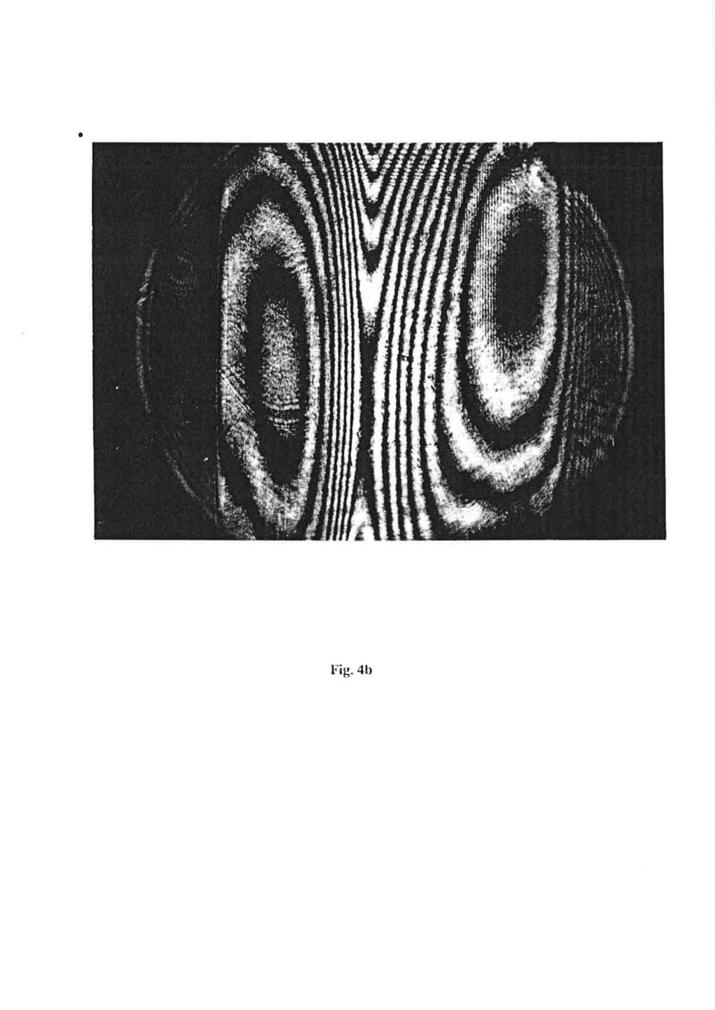
7 Measurements As a test of the measuring principle and set up, measurements on a 300 mm H-bar scale have been perfonned. In Figs. 4 a-c. interferograms are shown recorded on photographic films positioned in the plane of projection in the detection arm for a point on the middle of the scale. The most smooth and nice interference pattern was, as expected, obtained from the front surface of the scale, 4a. In figures 4b and 4c one can see that also the sides of the scale give with this technique interference patterns of good quality. An attempt to obtain interference fringes at nonnal incidence to the side surfaces gave no usable results. The ambiguity in the sign of the phase variations were resolved by observing the movements in the interference pattern when slightly moving the reference mirror. 3.3 Evaluation and results As was mentioned above the aperture of the interferometer is 17 mm, set by the beam expander. This diameter of the circular reference beam serve as a reference distance on the recorded interferograms, which can be used to determine the projected length of the scale, c.f. Fig. 4c. With the projected length and the true length (here 300 mm) known, the angle of incidence and the effective wavelength can be calculated using eq. 2. These values are collected in Table 1. For the recordings made here the effective wavelength were about 12 Jlm corresponding to a angle of incidence of some 2 deg. The estimated uncertainties in the effective wavelength, using eq. 5, and the value d~a=o.1 mm, are included in the parentheses in the fifth column in Table 1. Phase maps ofthe interference area were evaluated in a 11x11 matrix giving 121 data points. Since the phase function is evaluated in discrete points a numerical low pass filter step has been applied to filter out surface function frequencies contained under the Nyquist frequency. If the surface function does contain higher frequencies these will be lost in this step and a certain alaising will occur. For the purpose of demonstration we assume rapid changes in the surface function to be small and we will make no further considerations about such effects here in this report. The corresponding surface functions obtained using equation 1, the effective wavelength and the phase maps are shown in Figs. 5a-c.
8 -7- In Fig. 6a-c are shown profiles of the surface functions taken at the middle of the scale in the length direction. For these diagrams also the curved null surface, given in the interferometer, has been subtracted, giving more accurate data. One can see that the deviations are of the order of some tens of micrometers, as expected. The phase determination in the evaluation of the phase function can be made with an absolute error of de = 27t15 which then at each point give an maximum error of about 1 ~m using eq. 3. This is an effect of the limitations in manual evaluation. Electronic techniques would here improve the accuracy with at least a factor of ten. Furthermore, the uncertainties in the effective wavelengths, around 0.3 ~m, give for large values of e = 207t, a maximum error of about 1.5 ~m Thus the total maximum uncertainty, according to eq. 3, for the determination of the surface function is 2.5 ~m. 4 CONCLUSION It has been demonstrated that the technique using a projection of the studied surface indeed is a good way to determine the shape of standard scales. With the technique described here a measurement of the shape of the different sides of the scale can be made in some few minutes, provided a fixed set up and computerized data evaluation. The uncertainty in this measurement is limited by the manual evaluation of the interferogram and the determination of the effective wavelength to around 2.5 ~m. Shape measurements ought to be done on a regular basis; possibly every time the scale is calibrated to be able to make more firm conclusions in the case of unexpected values of the measured length. In principle this type of measurements could be done simultaneously with the length measurements (in our case inside the comparator chamber) to defmitely determine the shape in the position and environment where the accurate length measurement is made. For instance, effects like "bad holders",position instability, and alike could in this way be identified, at the same time as the surface function is determined and compared to earlier measurement to see if any geometrical change has occurred, possibly caused by improper handling routines. Several improvements of the set up described above can be made. Both the quality of the optics and size of the aperture in the interferometer should be improved. This would increase the working range and the accuracy. To further improve the dynamic range and to definitely resolve the phase ambiguities, a phase shifting technique would be well suited. Phase shifting
9 - 8 - interferometry for surface covering interferometers involve a large number of data processing and it is therefore almost necessary to use a computer. Digitalization of the interference pattern and transfer to a computer then gives better performance, result storage and presentation. September 1989
10 - 9 - REFERENCES [1] "Documents Concerning the New Definition of the Meter", Metrolo~ia. 19, 1984, pp [2] "The Continuity of the Meter: The Redefinition of the Meter and the Speed Of Visible Light", 1. of Res. of the National Bureau of Standards. 92, 1987, p. 11. [3] RAMON J., GIACOMO P. and CARRE P., International Comparison of Measurements of Line Scales , Metrolo~a. 24, 1987, pp [4] see reference [3], table 6a, data N 12. [5] ARCHBOLD E., BURCH J.M. and ENNOS A.E., I. Scir InstIum.. 44, 1967, pp
11 - 10- Table 1 Evaluation of effective wavelength for the three recordings 4a, 4b and 4c. Diameter photo Length photo Projected length Angle of incidence Effective wavelength I [mm] [mm] [mm] [deg] 125(1) 142(1) 130(1) 100(1) 100(1) 94(1) (27) 12.88(30) 12.55(30)
12 FIGURE CAPTIONS Fig. 1. Fig. 2. Fig. 3. Fig.4a The dotted curve shows the deviation in height from a line crossing the two end points of the surface. The solid curve gives the relative calibration (see text) forthe ten decimetre lines. The interferometric set up. Null surface measured in the interferometer. A curved background is seen as a result of limitations in the optical components used. Photographic recording of the interference pattern of the front side of the scale. Fig.4b Photographic recording of the interference pattern of one side of the scale. Fig.4c Photographic recording of the interference pattern of the other side of the scale. Fig.5a Fig.5b Fig.5c Fig.6a Fig.6b Fig.6c Surface function corresponding to the interferogram in Fig. 4a. Surface function corresponding to the interferogram in Fig. 4b. Surface function corresponding to the interferogram in Fig. 4c. Profile of the surface function taken at the middle of the scale in the length direction. Front side. Profile of the surface function taken at the middle of the scale in the length direction. Side. Profile of the surface function taken at the middle of the scale in the length direction. Side.
13 1,000 r , length height ---tr "A... "',;... '"... " If'" \\ "A /,/ \ I I \,,," \\ / '.'tf" \ I I \ \ I \ //"~ \, \ \ ", '" " o~--~~--~--~--~----~--~----~--~----~--~~o o Decimetre line Fig. 1
14 Laser beam Mirror Scale ~ Beam [ Expander ~ # # # ~ i:-- # Beam Splitter ~ I I~ Lens Mirror Fig. 2
15 1,000._ length height o~--~~--~-~-~~-~-~--~-~--~- ~o o Decimetre line Fig. 1
16 , Laser beam Scale ~ Beam [ Expander 0 Beam Splitter ~ ~ J Mirror # # # # I Lens -..J Mirror Fig. 2
17 Fig. 3
18 Fig.4b
19 Fig.4a
20 Fig.4c
21 Fig. Sa
22 Fig.5b
23 Fig. Se
24 Height [JAm] ~r , o~----~--~----~--~--~----~--~--~----~-- ~ o Decimetre line Fig.6a
25 Height [pm] 10r , o (10) (20) (30) (~)~~--~--~----~--~--~----~--~--~----~--~~ o Decimetre line Fig.6b
26 Height [pm] ~r ~ o~~--~----~--~----~--~----~--~----~--~----~~ o Decimetre line Fig.6c
Experiment O-2. The Michelson Interferometer
 Experiment O-2 The Michelson Interferometer The Michelson interferometer is one of the best known and historically important interferometers. It is a very accurate length-measuring device and has been
ABSTRACT. The following values for the wavelength of the sodium doublet lines were calculated:
 Determination of the wavelengths of the Sodium doublet lines and the measurement of the thickness of a thin transparent film using a Michelson interferometer Luke Pomfrey Tutor: Dr. P. Doel March 22, 2007
Michelson Interferometer
 Michelson Interferometer Objective Determination of the wave length of the light of the helium-neon laser by means of Michelson interferometer subsectionprinciple and Task Light is made to produce interference
Optical Metrology and Sensing
 Optical Metrology and Sensing Lecture 1: Introduction 2016-10-18 Herbert Gross Winter term 2016 www.iap.uni-jena.de 2 Preliminary Schedule No Date Subject Detailed Content 1 18.10. Introduction Introduction,
Introduction. Procedure. In this experiment, you'll use the interferometer to EQUIPMENT NEEDED: Lens 18mm FL. Component holder.
 12-7137A Precision Interferometer Experiment 1: Introduction to Interferometry EQUIPMENT NEEDED: Basic Interferometer (OS-9255A) Laser (OS-9171) Laser Alignment Bench (OS-9172) Interferometer Accessories
Probing the orbital angular momentum of light with a multipoint interferometer
 CHAPTER 2 Probing the orbital angular momentum of light with a multipoint interferometer We present an efficient method for probing the orbital angular momentum of optical vortices of arbitrary sizes.
Experiment 8 Michelson Interferometer
 Experiment 8 Michelson Interferometer Introduction This week s experiment utilizes the Michelson interferometer. You are to measure the wavelength of the green mercury light, the wavelength of the sodium
Comparative Measurement in Speckle Interferometry using Fourier Transform
 Egypt. J. Solids, Vol. (30), No. (2), (2007) 253 Comparative Measurement in Speckle Interferometry using Fourier Transform Nasser A. Moustafa Physics Department, Faculty of Science, Helwan University,
Metrology and Sensing
 Metrology and Sensing Lecture 1: Introduction 2016-10- Herbert Gross Winter term 2016 www.iap.uni-jena.de 2 Preliminary Schedule No Date Subject Detailed Content 1 18.10. Introduction Introduction, optical
The Michelson Interferometer
 Experiment #33 The Michelson Interferometer References 1. Your first year physics textbook. 2. Hecht, Optics, Addison Wesley - Chapter 9 in the 4th Ed. (2001). 3. Jenkins and White, Fundamentals of Optics
Experiment 2: The Speed of Light
 Experiment 2: The Speed of Light Modern Physics Laboratory Department of Physics and Astronomy Austin Peay State University September 12, 2006 Abstract In this experiment you will determine the value of
Interference- Michelson Interferometer. Interference lecture by Dr. T.Vishwam
 Interference- Michelson Interferometer Interference lecture by Dr. T.Vishwam * Measurement of the coherence length of a spectral line * Measurement of thickness of thin transparent flakes * Measurement
Measurements in Optics for Civil Engineers
 Measurements in Optics for Civil Engineers I. FOCAL LENGTH OF LENSES The behavior of simplest optical devices can be described by the method of geometrical optics. For convex or converging and concave
5. LIGHT MICROSCOPY Abbe s theory of imaging
 5. LIGHT MICROSCOPY. We use Fourier optics to describe coherent image formation, imaging obtained by illuminating the specimen with spatially coherent light. We define resolution, contrast, and phase-sensitive
Coherence and width of spectral lines with Michelson interferometer
 Coherence and width of spectral lines TEP Principle Fraunhofer and Fresnel diffraction, interference, spatial and time coherence, coherence conditions, coherence length for non punctual light sources,
LIGO I mirror scattering loss by non smooth surface structure
 LASER INTERFEROMETER GRAVITATIONAL WAVE OBSERVATORY LIGO Laboratory / LIGO Scientific Collaboration LIGO-T070170-00-E LIGO July 26, 2007 LIGO I mirror scattering loss by non smooth surface structure Hiro
Absolute length measurement using multiple-wavelength phase-stepping interferometry
 UNIVERSITY OF LONDON 1 IMPERIAL COLLEGE OF SCIENCE,TECHNOLOGY AND MEDICINE DEPARTMENT OF PHYSICS APPLIED OPTICS GROUP Absolute length measurement using multiple-wavelength phase-stepping interferometry
Experiment 6: Interferometers
 Experiment 6: Interferometers Nate Saffold nas2173@columbia.edu Office Hour: Mondays, 5:30PM-6:30PM @ Pupin 1216 INTRO TO EXPERIMENTAL PHYS-LAB 1493/1494/2699 NOTE: No labs and no lecture next week! Outline
Interferometers. PART 1: Michelson Interferometer The Michelson interferometer is one of the most useful of all optical instru
 Interferometers EP421 Lab Interferometers Introduction: Interferometers are the key to accurate distance measurement using optics. Historically, when mechanical measurements dominated, interferometers
Optical Interferometry
 Optical Interferometry MIT Department of Physics The objective of this experiment is to observe the interference of light by combining coherent monochromatic light beams using a Michelson interferometer.
The Michelson Interferometer as a Device for Measuring the Wavelength of a Helium-Neon Laser
 Journal of Advanced Undergraduate Physics Laboratory Investigation Volume 3 2017-2018 Article 2 2018 The Michelson Interferometer as a Device for Measuring the Wavelength of a Helium-Neon Laser Carly E.
Metrology and Sensing
 Metrology and Sensing Lecture 5: Interferometry I 06--09 Herbert Gross Winter term 06 www.iap.uni-jena.de Preliminary Schedule No Date Subject Detailed Content 8.0. Introduction Introduction, optical measurements,
Introduction to FT-IR Spectroscopy
 Introduction to FT-IR Spectroscopy An FT-IR Spectrometer is an instrument which acquires broadband NIR to FIR spectra. Unlike a dispersive instrument, i.e. grating monochromator or spectrograph, an FT-IR
Laser Speckle and Applications in Optics
 Laser Speckle and Applications in Optics M. FRANCON Optics Laboratory Faculty of Sciences University of Paris Paris, France Translated by HENRI H. ARSENAULT Department of Physics Laval University Quebec,
PS210 - Optical Techniques. Section VI
 PS210 - Optical Techniques Section VI Section I Light as Waves, Rays and Photons Section II Geometrical Optics & Optical Instrumentation Section III Periodic and Non-Periodic (Aperiodic) Waves Section
Speed of Light in Air
 Speed of Light in Air Electromagnetic waves represent energy in the form of oscillating electric and magnetic fields which propagate through vacuum with a speed c = 2.9979246x10 8 m/s. Electromagnetic
ROTATIONAL SHEARING INTERFEROMATER. Introduction. The Interferometer. L. Yeswanth, Optics Group, IIA, Bangalore
 ROTATIONAL SHEARING INTERFEROMATER L. Yeswanth, Optics Group, IIA, Bangalore Introduction A rotational shearing interferometer is a modification of the Michelson s interferometer to obtain the spatial
10. OPTICAL COHERENCE TOMOGRAPHY
 1. OPTICAL COHERENCE TOMOGRAPHY Optical coherence tomography (OCT) is a label-free (intrinsic contrast) technique that enables 3D imaging of tissues. The principle of its operation relies on low-coherence
Low Coherence Vibration Insensitive Fizeau Interferometer
 Low Coherence Vibration Insensitive Fizeau Interferometer Brad Kimbrough, James Millerd, James Wyant, John Hayes 4D Technology Corporation, 3280 E. Hemisphere Loop, Suite 146, Tucson, AZ 85706 (520) 294-5600,
PRINCIPLES OF PHYSICAL OPTICS
 PRINCIPLES OF PHYSICAL OPTICS C. A. Bennett University of North Carolina At Asheville WILEY- INTERSCIENCE A JOHN WILEY & SONS, INC., PUBLICATION CONTENTS Preface 1 The Physics of Waves 1 1.1 Introduction
Experiment 3 1. The Michelson Interferometer and the He- Ne Laser Physics 2150 Experiment No. 3 University of Colorado
 Experiment 3 1 Introduction The Michelson Interferometer and the He- Ne Laser Physics 2150 Experiment No. 3 University of Colorado The Michelson interferometer is one example of an optical interferometer.
Let us consider a typical Michelson interferometer, where a broadband source is used for illumination (Fig. 1a).
.") 7.1. Low-Coherence Interferometry (LCI) Let us consider a typical Michelson interferometer, where a broadband source is used for illumination (Fig. 1a). The light is split by the beam splitter (BS) and
7.1. Low-Coherence Interferometry (LCI) Let us consider a typical Michelson interferometer, where a broadband source is used for illumination (Fig. 1a). The light is split by the beam splitter (BS) and
Particle-Wave Duality and Which-Way Information
 Particle-Wave Duality and Which-Way Information Graham Jensen and Samantha To University of Rochester, Rochester, NY 14627, U.S. September 25, 2013 Abstract Samantha To This experiment aimed to support
Chapter 5. Past and Proposed Experiments Detecting Absolute Motion
 Chapter 5 Past and Proposed Experiments Detecting Absolute Motion In this Chapter I gave different interpretations for the results of some famous past experiments. My interpretations are based on the following
Measurments with Michelson interferometers
 Please do not remove this manual from from the lab. It is available at www.cm.ph.bham.ac.uk/y2lab Optics Measurments with Michelson interferometers Objectives In this experiment you will: Understand the
THE ZEEMAN EFFECT PHYSICS 359E
 THE ZEEMAN EFFECT PHYSICS 359E INTRODUCTION The Zeeman effect is a demonstration of spatial quantization of angular momentum in atomic physics. Since an electron circling a nucleus is analogous to a current
8. The Michelson Interferometer
 M 8. The Michelson Interferometer 8.1 Introduction Interference patterns from superposed coherent waves may be used for precise determination of wavelength or, if the wavelength is known, time-of-flight,
PHYS 229: Experiment 1 Expansion Coefficients of Copper and Invar Bars Through Laser Interferometry
 PHYS 229: Experiment 1 Expansion Coefficients of Copper and Invar Bars Through Laser Interferometry Jack Hong 30935134 Partner: Omar Mrani Zentar January 15, 2015 1 Introduction: When objects are heated,
Fabry-Perot Interferometer for atmospheric monitoring useful for EAS detection E.Fokitis 1, K. Patrinos 1, Z. Nikitaki 1
 Fabry-Perot Interferometer for atmospheric monitoring useful for EAS detection E.Fokitis 1, K. Patrinos 1, Z. Nikitaki 1 ABSTRACT A piezotunable Fabry-Perot interferometer is studied as a candidate Doppler
Michelson Interferometry and Measurement of the Sodium Doublet Splitting
 Michelson Interferometry and Measurement of the Sodium Doublet Splitting PHYS 3330: Experiments in Optics Department of Physics and Astronomy, University of Georgia, Athens, Georgia 30602 (Dated: Revised
COMPUTER GENERATED HOLOGRAMS Optical Sciences 627 W.J. Dallas (Monday, August 23, 2004, 12:14 PM)
") COMPUTER GENERATED HOLOGRAMS Optical Sciences 67 W.J. Dallas (Monday, August 3, 4, 1:14 PM) PART IV: CHAPTER FOUR OPTICAL TESTING Part IV: Chapter Four Page 1 of 1 Introduction In optical testing an element
COMPUTER GENERATED HOLOGRAMS Optical Sciences 67 W.J. Dallas (Monday, August 3, 4, 1:14 PM) PART IV: CHAPTER FOUR OPTICAL TESTING Part IV: Chapter Four Page 1 of 1 Introduction In optical testing an element
iprom Optical Interferometry Prof. Dr. -Ing. Rainer Tutsch Institut für Produktionsmesstechnik IPROM Technische Universität Braunschweig
 Optical Interferometry Prof. Dr. -Ing. Rainer Tutsch Institut für Produktionsmesstechnik IPROM Technische Universität Braunschweig Frontiers of Metrology April 1, 01 I P NSTITUT FÜR RODUKTIONSMESSTECHNIK
Light as a Transverse Wave.
 Waves and Superposition (Keating Chapter 21) The ray model for light (i.e. light travels in straight lines) can be used to explain a lot of phenomena (like basic object and image formation and even aberrations)
Fourier Transform Spectrograph Development Project
 Fourier Transform Spectrograph Development Project NARIT Research Colloquium / Research Project Evaluation 2018 August 2 nd, Flora Creek Hotel, Chiangmai C. Buisset 1, P. Artsang 2, P. Meemon 2, 1 National
MEMS Metrology. Prof. Tianhong Cui ME 8254
 MEMS Metrology Prof. Tianhong Cui ME 8254 What is metrology? Metrology It is the science of weights and measures Refers primarily to the measurements of length, weight, time, etc. Mensuration- A branch
Simulation of laser propagation in plasma chamber including nonlinearities by utilization of VirtualLab 5 software
 Simulation of laser propagation in plasma chamber including nonlinearities by utilization of VirtualLab 5 software DESY Summer Student Programme, 2012 Anusorn Lueangaramwong Chiang Mai University, Thailand
International Journal of Scientific & Engineering Research, Volume 4, Issue 7, July ISSN
 International Journal of Scientific & Engineering Research, Volume 4, Issue 7, July-2013 96 Performance and Evaluation of Interferometric based Wavefront Sensors M.Mohamed Ismail1, M.Mohamed Sathik2 Research
The science of light. P. Ewart
 The science of light P. Ewart Oxford Physics: Second Year, Optics Parallel reflecting surfaces t images source Extended source path difference xcos 2t=x Fringes localized at infinity Circular fringe constant
THE MICHELSON INTERFEROMETER Intermediate ( first part) to Advanced (latter parts)
 to Advanced (latter parts)") THE MICHELSON INTERFEROMETER Intermediate ( first part) to Advanced (latter parts) Goal: There is a progression of goals for this experiment but you do not have to do the last goal. The first goal is to
THE MICHELSON INTERFEROMETER Intermediate ( first part) to Advanced (latter parts) Goal: There is a progression of goals for this experiment but you do not have to do the last goal. The first goal is to
Light as Wave Motion p. 1 Huygens' Ideas p. 2 Newton's Ideas p. 8 Complex Numbers p. 10 Simple Harmonic Motion p. 11 Polarized Waves in a Stretched
 Introduction p. xvii Light as Wave Motion p. 1 Huygens' Ideas p. 2 Newton's Ideas p. 8 Complex Numbers p. 10 Simple Harmonic Motion p. 11 Polarized Waves in a Stretched String p. 16 Velocities of Mechanical
Computer aided measurement of biomechanical characteristics of cadaverous lumbar spines
 CEJP 2(3) 2004 504 510 Computer aided measurement of biomechanical characteristics of cadaverous lumbar spines Luděk Bartoněk 1,JiříKeprt 2,Jiří Charamza 3, Lumír Hrabálek 4 1 Department of Experimental
Figure measurement of a large optical flat with a Fizeau interferometer and stitching technique
 Figure measurement of a large optical flat with a Fizeau interferometer and stitching technique Chunyu Zhao a, Robert A. Sprowl a, Michael Bray b, James H. Burge a a College of Optical Sciences, the University
5 TH ERMAL GRADIENT INTERFEROMETRIC MEASUREMENT
 5 TH ERMAL GRADIENT INTERFEROMETRIC MEASUREMENT Gradient Index Measurement with Temperature MODEL OEK-100 PROJECT #4 50 5.1 Introduction It is possible to measure the change in index of refraction of a
An Interferometric Force Probe for Thruster Plume Diagnostics
 An Interferometric Force Probe for Thruster Plume Diagnostics IEPC-2015-419/ISTS-2015-b-419 Presented at Joint Conference of 30th International Symposium on Space Technology and Science, 34th International
THE MEASUREMENT OF SOLAR ULTRAVIOLET SPECTRAL IRRADIANCE PROBLEMS & SOLUTIONS
 THE MEASUREMENT OF SOLAR ULTRAVIOLET SPECTRAL IRRADIANCE PROBLEMS & SOLUTIONS INTRODUCTION In recent years, researchers involved in many unrelated scientific disciplines have acquired an interest in accurately
LASER TRAPPING MICRO-PROBE FOR NANO-CMM
 LASER TRAPPING MICRO-PROBE FOR NANO-CMM T. Miyoshi, Y. Takaya and S. Takahashi Division of Production and Measurement System Engineering Department of Mechanical Engineering and Systems Osaka University,
INTERFEROMETERS. There are 4 principal types of measurements that can be made with this type of interferometer.
 INTERFEROMETERS NOTE: Most mirrors in the apparatus are front surface aluminized. Do not touch the surfaces nor wipe them. they can be easily permanently damaged. Introduction This experiment provides
Path Entanglement. Liat Dovrat. Quantum Optics Seminar
 Path Entanglement Liat Dovrat Quantum Optics Seminar March 2008 Lecture Outline Path entangled states. Generation of path entangled states. Characteristics of the entangled state: Super Resolution Beating
Fringe shifts in multiple-beam Fizeau interferometry
 638 J. Opt. Soc. Am./Vol. 72, No. 5/May 1982 Fringe shifts in multiple-beam Fizeau interferometry Optical Sciences Center, University of Arizona, Tucson, Arizona 85721 Received August 7,1981; revised manuscript
Optical Tweezers. The Useful Micro-Manipulation Tool in Research
 Optical Tweezers The Useful Micro-Manipulation Tool in Research Student: Nikki Barron Class: Modern Physics/ Biophysics laboratory Advisor: Grant Allen Instructor: David Kleinfeld Date: June 15, 2012 Introduction
Optics.
 Optics www.optics.rochester.edu/classes/opt100/opt100page.html Course outline Light is a Ray (Geometrical Optics) 1. Nature of light 2. Production and measurement of light 3. Geometrical optics 4. Matrix
Chapter 10. Interference of Light
 Chapter 10. Interference of Light Last Lecture Wave equations Maxwell equations and EM waves Superposition of waves This Lecture Two-Beam Interference Young s Double Slit Experiment Virtual Sources Newton
Using dispersion-induced group delay to solve the integer ambiguity problem: a theoretical analysis
 J. Eur. Opt. Soc.-Rapid 10, 15035 (2015) www.jeos.org Using dispersion-induced group delay to solve the integer ambiguity problem: a theoretical analysis D. Wei weidong@mech.nagaokaut.ac.jp Department
MODERN INTERFEROMETRY
 MODERN INTERFEROMETRY * No actual laser photons were harmed during the filming of this cover. Build Michelson, Sagnac, and Mach-Zehnder Interferometers Generate and Count Interference Fringes Manually
Supporting Online Material for
 www.sciencemag.org/cgi/content/full/326/5955/974/dc1 Supporting Online Material for Observation of Half-Quantum Vortices in an Exciton-Polariton Condensate K. G. Lagoudakis,* T. Ostatnický, A. V. Kavokin,
2.71. Final examination. 3 hours (9am 12 noon) Total pages: 7 (seven) PLEASE DO NOT TURN OVER UNTIL EXAM STARTS PLEASE RETURN THIS BOOKLET
 Total pages: 7 (seven) PLEASE DO NOT TURN OVER UNTIL EXAM STARTS PLEASE RETURN THIS BOOKLET") 2.71 Final examination 3 hours (9am 12 noon) Total pages: 7 (seven) PLEASE DO NOT TURN OVER UNTIL EXAM STARTS Name: PLEASE RETURN THIS BOOKLET WITH YOUR SOLUTION SHEET(S) MASSACHUSETTS INSTITUTE OF TECHNOLOGY
2.71 Final examination 3 hours (9am 12 noon) Total pages: 7 (seven) PLEASE DO NOT TURN OVER UNTIL EXAM STARTS Name: PLEASE RETURN THIS BOOKLET WITH YOUR SOLUTION SHEET(S) MASSACHUSETTS INSTITUTE OF TECHNOLOGY
Renewal of the gage-block interferometer at INRIM
 Renewal of the gage-block interferometer at INRIM R. Bellotti, M. Franco, G. B. Picotto* and M. Pometto Istituto Nazionale di Ricerca Metrologica (INRIM), Strada delle Cacce 73, 10135 Torino, Italy * Corresponding
Optical Systems Program of Studies Version 1.0 April 2012
 Optical Systems Program of Studies Version 1.0 April 2012 Standard1 Essential Understand Optical experimental methodology, data analysis, interpretation, and presentation strategies Essential Understandings:
Speckle phenomenon and its potential for metrology
 Joint International Physics Summer School Optics (Olomouc, August 28 September 01, 2017) Speckle phenomenon and its potential for metrology Pavel Horváth* & Petr Šmíd** *Palacký University, Faculty of
Constructive vs. destructive interference; Coherent vs. incoherent interference
 Constructive vs. destructive interference; Coherent vs. incoherent interference Waves that combine in phase add up to relatively high irradiance. = Constructive interference (coherent) Waves that combine
Michelson Interferometer. crucial role in Einstein s development of the Special Theory of Relativity.
 Michelson Interferometer The interferometer Michelson experiment Interferometer of Michelson and Morley played 0 a crucial role in Einstein s development of the Special Theory of Relativity. Michelson
Homogeneity of optical glass
 1 Version ebruary 2016 Introduction SCHOTT offers machined optical glasses with homogeneities up to H5 quality. I-Line glasses can even be offered in higher homogeneities. The achievable homogeneity depends
Standard Small Angle Generator Using Laser Interferometer
 40 Kasetsart J. (Nat. Sci.) 40 : 40-47 (2006) Kasetsart J. (Nat. Sci.) 40(5) Standard Small Angle Generator Using Laser Interferometer Kittisak Nugkim 1, Kanokpoj Areekul 1 * and Bancha Panacharoensawad
Interferometric determination of thermal expansion coefficient of piston/cylinder unit preliminary investigation
 Journal of Physics: Conference Series PAPER OPEN ACCESS Interferometric determination of thermal expansion coefficient of piston/cylinder unit preliminary investigation To cite this article: L Grgec Bermanec
Speed Measurement by Optical Techniques. Lucas Thoennes
 Speed Measurement by Optical Techniques Lucas Thoennes Published 2-22-2018 Department of Physics and Astronomy, University of New Mexico 1 University of New Mexico, Albuquerque, NM 87131 lthoennes@unm.edu
Thermal Imaging at Multiple Time Instants for Study of Self-Heating and ESD Phenomena
 Thermal Imaging at Multiple Time Instants for Study of Self-Heating and ESD Phenomena V. Dubec, S. Bychikhin, M. Blaho, M. Heer, D. Pogan E. Gornik Institute of Solid State Electronics, Vienna University
Strain Analysis by Digital Shearography on an Aluminium Plate with a Geometric Defect under Thermal Loading
 Journal of Stress Analysis Vol. 1, No. 1, Spring Summer 2016 Strain Analysis by Digital Shearography on an Aluminium Plate with a Geometric Defect under Thermal Loading R. Moharrami, M. Taghiloo, A. Darud
Effect of piezoelectric transducer nonlinearity on phase shift interferometry
 Effect of piezoelectric transducer nonlinearity on phase shift interferometry Chiayu Ai and James C. Wyant If the nonlinearity of the motion of a piezoelectric transducer (PZT) can be described as a quadratic
Wavefront Sensing using Polarization Shearing Interferometer. A report on the work done for my Ph.D. J.P.Lancelot
 Wavefront Sensing using Polarization Shearing Interferometer A report on the work done for my Ph.D J.P.Lancelot CONTENTS 1. Introduction 2. Imaging Through Atmospheric turbulence 2.1 The statistics of
POLARIZATION OF LIGHT
 POLARIZATION OF LIGHT OVERALL GOALS The Polarization of Light lab strongly emphasizes connecting mathematical formalism with measurable results. It is not your job to understand every aspect of the theory,
Optical Shop Testing. Second Edition. Edited by DANIEL MALACARA. John Wiley & Sons, Inc. A Wiley-Interscience Publication
 Optical Shop Testing Second Edition Edited by DANIEL MALACARA A Wiley-Interscience Publication John Wiley & Sons, Inc. New York I Chichester I Brisbane I Toronto I Singapore Contents Preface to the Second
Low-coherence heterodyne photon correlation spectroscopy
 Low-coherence heterodyne photon correlation spectroscopy J.H. Johnson, S.L. Siefken, A. Schmidt, R. Corey, and P. Saulnier Department of Physics, Gustavus Adolphus College Saint Peter, MN 56082 ABSTRACT
Correction of Errors in Polarization Based Dynamic Phase Shifting Interferometers
 Correction of Errors in Polarization Based Dynamic Phase Shifting Interferometers Bradley Kimbrough 4D Technology Corporation, Tucson Arizona brad.kimbrough@4dtechnology.com 1 Introduction Polarization
A phase shifting interferometeric imaging ellipsometer
 A phase shifting interferometeric imaging ellipsometer Conrad Weilsa and James C. Wyant aoptical Sciences Center, University of Arizona, Tucson, AZ 8572 1-0094 bwyko Corporation, 2650 East Elvira Road,
Recent progress in SR interferometer
 Recent progress in SR interferometer -for small beam size measurement- T. Mitsuhashi, KEK Agenda 1. Brief introduction of beam size measurement through SR interferometry. 2. Theoretical resolution of interferometry
Liquid refractometer based on immersion diffractometry
 Liquid refractometer based on immersion diffractometry Sheng-Hua Lu, 1 Shan-Peng Pan, Tzong-Shi Liu, and Ching-Fen Kao 3 1 Department of Photonics, Feng Chia University, Taichung, Taiwan 4074, R.O.C. Department
A faster, more accurate way of characterizing cube beamsplitters using the Agilent Cary 7000 Universal Measurement Spectrophotometer (UMS)
") A faster, more accurate way of characterizing cube beamsplitters using the Agilent Cary 7000 Universal Measurement Spectrophotometer (UMS) Application note Materials Authors Travis Burt, Chris Colley,
A faster, more accurate way of characterizing cube beamsplitters using the Agilent Cary 7000 Universal Measurement Spectrophotometer (UMS) Application note Materials Authors Travis Burt, Chris Colley,
1. Consider the biconvex thick lens shown in the figure below, made from transparent material with index n and thickness L.
 Optical Science and Engineering 2013 Advanced Optics Exam Answer all questions. Begin each question on a new blank page. Put your banner ID at the top of each page. Please staple all pages for each individual
LAB DEMONSTRATION OF INTERFEROMETRIC
 LAB DEMONSTRATION OF INTERFEROMETRIC MEASUREMENT USING A TEST PLATE AND CGH Presented to: Larry Stepp Eric Hansen The Association of Universities for Research in Astronomy, Inc. Tucson, AZ, 85726 Prepared
Chemistry Instrumental Analysis Lecture 15. Chem 4631
 Chemistry 4631 Instrumental Analysis Lecture 15 IR Instruments Types of Instrumentation Dispersive Spectrophotometers (gratings) Fourier transform spectrometers (interferometer) Single beam Double beam
Dimension measurement. By Mr.Vuttichai Sittiarttakorn
 Dimension measurement By Mr.Vuttichai Sittiarttakorn 1 LECTURE OUTLINE 1. Introduction 2. Standards and Calibration 3. Relative displacement : Translational and Rotational 4. displacement transducers Potentiometers
LABORATORY WRITE-UP MICHELSON INTERFEROMETER LAB AUTHOR S NAME GOES HERE STUDENT NUMBER:
 LABORATORY WRITE-UP MICHELSON INTERFEROMETER LAB AUTHOR S NAME GOES HERE STUDENT NUMBER: 111-22-3333 MICHELSON INTERFEROMETER 1. PURPOSE The purpose of this experiment is to give some practice in using
Machine Positioning Uncertainty with Laser Interferometer Feedback
 Machine Positioning Uncertainty with Laser Interferometer Feedback The purpose of this discussion is to explain the major contributors to machine positioning uncertainty in systems with laser interferometer
Experiment 4. Michelson Interferometer. 4.1 Introduction. References
 Experiment 4 Michelson Interferometer References Optics by E. Hecht, Section 9.4.2 Fundamentals of Optics by F. Jenkins & H. White, Chapter 13, Sections 8 through 15, and Chapter 14, Section 13 An Introduction
Imaging through Kolmogorov model of atmospheric turbulence for shearing interferometer wavefront sensor
 Imaging through Kolmogorov model of atmospheric turbulence for shearing interferometer wavefront sensor M.Mohamed Ismail 1 M.Mohamed Sathik 2 1Research Scholar, Department of Computer Science, Sadakathullah
Phase-conjugation of high power molecular C02 and CO lasers radiation inside their active medium
 Phase-conjugation of high power molecular C02 and CO lasers radiation inside their active medium L.Afanas'ev, A.Ionin, Yu.Klimachev, A.Kotkov, D.Sinitsyn P.N.Lebedev Physics Institute ofrussian Academy
Research Article Noncontact Measurement for Radius of Curvature of Unpolished Lens
 International Optics, Article ID 3403, 7 pages http://dx.doi.org/10.1155/014/3403 Research Article Noncontact Measurement for Radius of Curvature of Unpolished Lens Haifeng Liang College of Photoelectrical
Metrology and Sensing
 Metrology and Sensing Lecture 5: Interferometry I 08--6 Herbert Gross Winter term 08 www.iap.uni-jena.de Schedule Optical Metrology and Sensing 08 No Date Subject Detailed Content 6.0. Introduction Introduction,
LASER APPLICATIONS XII. QPR No Academic Research Staff. Ezekiel. Prof. S. Graduate Students
 XII. LASER APPLICATIONS Academic Research Staff Prof. S. Ezekiel Graduate Students L. A. Hackel J. A. Monjes J. P. Sullivan P. D. Henshaw T. J. Ryan D. G. Youmans J. W. Stafurik RESEARCH OBJECTIVES Our
CHAPTER 9 PERFORMANCE OF THE INTERFEROMETER
 Performance of the interferometer 235 CHAPTER 9 PERFORMANCE OF THE INTERFEROMETER Deus ex machina. ( A god from the machine. ) Menander 9.1 ASSESSMENT OF THE INTERFEROMETER One major problem in assessing