Non-Hydrostatic Pressure Shallow Flows: GPU Implementation Using Finite Volume and Finite Difference Scheme.
|
|
|
- Giles York
- 5 years ago
- Views:
Transcription
1 arxiv: v [math.na] 1 Jul 018 Non-Hydrostatic Pressure Shallow Flows: GPU Implementation Using Finite Volume and Finite Difference Scheme. C. Escalante 1 T. Morales de Luna and M.J. Castro 1 1 Departamento de Análisis Matemático Estadística e Investigación Operativa y Matemática Aplicada Universidad de Málaga Spain Departamento de Matemáticas Universidad de Córdoba Spain June Abstract We consider the depth-integrated non-hydrostatic system derived by Yamazaki et al. An efficient formally second-order well-balanced hybrid finite volume finite difference numerical scheme is proposed. The scheme consists of a two-step algorithm based on a projectioncorrection type scheme initially introduced by Chorin-Temam [15]. First the hyperbolic part of the system is discretized using a Polynomial Viscosity Matrix path-conservative finite volume method. Second the dispersive terms are solved by means of compact finite differences. A new methodology is also presented to handle wave breaking over complex bathymetries. This adapts well to GPU-architectures and guidelines about its GPU implementation are introduced. The method has been applied to idealized and challenging experimental test cases which shows the efficiency and accuracy of the method. address: escalante@uma.es; Corresponding author 1
2 Keywords: Non-hydrostatic Shallow-Water Finite Difference Finite Volume GPU Tsunami Simulation Wave Breaking 1 Introduction When modelling and simulating geophysical flows the Nonlinear Shallow- Water equations hereinafter SWE are often a good choice as an approximation of the Navier-Stokes equations. Nevertheless SWE do not take into account effects associated with dispersive waves. In recent years effort has been made in the derivation of relatively simple mathematical models for shallow water flows that include long nonlinear water waves. As computational power increases Boussinesq-type Models ([1] [5] [0] [9] [3] [33] [1] [39] [40]) become more accessible. This means that one can use more sophisticated models in order to improve the description of reality despite the higher computational cost. Moreover in order to improve nonlinear dispersive properties of the model information on the vertical structure of the flow should be included. The Boussinesq-type wave equations have prevailed due to their computational efficiency. The main idea is to include non-hydrostatic effects due to the vertical acceleration of the fluid in the depth-averaging process of the equations. For instance one can assume that both non-linearity and frequency dispersion are weak and of the same order of magnitude. Since the early works of Peregrine [33] several improved and enhanced Boussinesq models have been proposed over the years: Madsen and Sørensen [9] Nwogu [3] Serre Green-Naghdi equations [0] and nonlinear and non-hydrostatic higher order Shallow-Water type models [7] [41] among many others. One may use different approaches to improve nonlinear dispersive properties of the models: to consider a Taylor expansion of the velocity potential in powers of the vertical coordinate and in terms of the depth-averaged velocity [9] or the particle velocity components (u w) at a chosen level [3]; to use a better flow resolution in the vertical direction with a multi-layer approach [6]; to include non-hydrostatic effects in the depth-averaging process ([41] [7]). The development of non-hydrostatic models for coastal water waves has been the topic of many studies over the past 15 years. Non-hydrostatic models are capable of solving many relevant features of coastal water waves
3 such as dispersion non-linearity shoaling refraction diffraction and run-up (see [ ]). The approach used by Yamazaki in [41] has the advantage of including such non-hydrostatic effects while not adding excessive complexity to the model. This is an advantage from the practical point of view and we will use this technique in this paper. In this work an already proposed non-hydrostatic pressure system is revisited and some new features are proposed that contributes to the development of an accurate and efficient tool for the simulation of dispersive water waves involving breaking waves wet-dry fronts and propagation of solitary waves over big domains. In order to deal with wet-dry fronts in an accurate manner we have found in several works that the state of the art when dealing with non-hydrostatic pressure systems consists in to set to zero the non-hydrostatic pressure for some threshold value (see [41]). In this work thanks to the rewriting of the incompressibility condition the non-hydrostatic pressure tends automatically to zero when the water height tends to zero. This is a nice feature since the only treatment in presence of wet-dry fronts is the redefinition of the hydrostatic pressure term for emerging topographies (to avoid nonphysical spurious forces) and the use of a desingularization formula for the computation of velocities when small values of water heights appears. As is well known in general non-hydrostatic pressure and in particular the one studied in this paper can not deal when breaking waves arises. In such situations one must use a breaking mechanism in order to dissipate the amount of energy associated to turbulence effects when breaking. As we will discuss in the present paper there are two strategies when dealing with it: the first one is to set the non-hydrostatic pressure to be zero when a breaking wave is detected. This raises the problem that the convergence of the numerical solution is not ensured when the mesh is refined and a global and costly criteria must be considered (see [3]). The second strategy is to introduce a new physical viscosity term to the horizontal momentum equation. This new term introduces a new parabolic term that must be discretized conveniently. In this work we propose a new writing of a classical breaking term which allows us to solve the final system in an efficient way. In this work we will also propose a numerical algorithm that is massively parallelizable and we will implement it on GPUs architectures. The proposed implementation which is described in the paper allows us to compute numerical solutions in big computational domains. This is done using a solely 3
4 graphic card and reaching a speed-up 110 times faster when compared with a sequential code. The proposed numerical scheme and its implementation for the non-hydrostatic pressure system presents efficient computational times which are notably similar to an efficient implementation of an hydrostatic shallow water code. This can be stated in fact as the main scientific contribution of this work which is an advancement and improvement in the field of numerical modelling and numerical simulation of dispersive water waves and in particular for non-hydrostatic pressure shallow water system. The paper is organized as follows. In Section the model is described. In Section 3 breaking mechanism is discussed. The reader should keep in mind that detailed small-scale breaking driven physics are not described by the model. This means that one has to include some breaking mechanism in the depth-integrated equations as it is done by an ad-hoc submodel similar to [35]. In Section 4 a numerical scheme is introduced based on a two-step algorithm. On the first step we solve the SWE in conservative form and on the second step we include the non-hydrostatic effects. The extension of the scheme to the D case is introduced in Section 5. In Section 6 guidelines for the GPU implementation of the numerical scheme presented in the previous section are given. Finally in Section 7 some numerical tests including comparisons with laboratory data are shown. Governing equations In [41] a D non-hydrostatic model was presented. The governing equations are derived from the incompressible Navier-Stokes equations. The equations are obtained by a process of depth averaging on the vertical direction z. Unlike it is done for SWE the pressure is not assumed hydrostatic. Following Stelling and Zijlema [36] and Casulli [14] total pressure is decomposed into a sum of hydrostatic and non-hydrostatic pressures. In order to provide the dynamic free-surface boundary condition non-hydrostatic pressure is assumed to be zero at free surface level. In the process of depth averaging the vertical velocity is supposed to have linear vertical profile. Moreover in the vertical momentum equation the vertical advective and dissipative terms which are assumed to be small compared with their horizontal counterparts are neglected. The resulting x y and z momentum equations as well as the continuity equation described in [41] are 4
 contains the depth averaged velocities components in the x and y directions respectively. w is the depth averaged velocity component in the z direction.")
5 h t + q = 0 ( ) q q q t + div h hw t = p ( 1 + gh + 1 ) hp = (gh + p) H τ (1) u + W η W b h = 0 where t is time and g is gravitational acceleration. u = (u v) contains the depth averaged velocities components in the x and y directions respectively. w is the depth averaged velocity component in the z direction. q = hu is the discharge vector in the x and y directions. W η and W b are the vertical velocities at the free-surface and bottom. p is the non-hydrostatic pressure at the bottom. The flow depth is h = η + H where η is the surface elevation measured from the still-water level H is the still water depth (see Figure 1). Here we use a Manning friction law given by τ = gh n u u h 4/3 where n is the Gauckler-Manning coefficient (see [30]). Operators and div denote the gradient vector field and the divergence respectively in the (x y) direction. The vertical velocity at the bottom is evaluated from the boundary condition W b = u H. () Figure 1: Sketch of the domain for the fluid problem 5
6 We will rewrite the system in order to express it in terms of the conserved quantities h q and w. Due to the assumption of a linear profile of the vertical velocity W one has W = W b + (z + H) W η W b h and thus the integration of W over z [ H η] gives and therefore w = 1 h η H W dz = W η + W b Due to the boundary conditions () and (3) it holds W η W b h and thus the last equation in system (1) becomes W η = w W b. (3) u + w + u H h/ = w + u H (4) h/ = 0. (5) Finally equation (5) is multiplied by h so that it is rewritten in the form and the system (1) is rewritten as: h q q (η h) + hw = 0 (6) h t + q = 0 ( ) q q q t + div h hw t = p h q q (η h) + hw = 0. ( 1 + gh + 1 ) hp = (gh + p) H τ (7) If we consider in system (1) the vertical velocity equation (hw) t + (hwu) x = p 6
7 then system (7) matches with the one proposed in [7]. In this case the system verifies an exact energy balance. This property can not be guaranteed for the approach used by Yamazaki in [41] but it has the advantage of not adding excessive complexity to the model. Nevertheless the numerical scheme proposed in this work can be easily extended to the model proposed in [7]. From the numerical point of view the results considered in this work do not present relevant differences when comparing both alternatives (see [3 7]) 3 Breaking wave modelling As pointed in [35] in shallow water complex events can be observed related to turbulent processes. One of these processes corresponds to the breaking of waves near the coast. As it will be seen in the numerical tests proposed in this work the model presented here cannot describe this process without an additional term which allows the model to dissipate the required amount of energy on such situations. When breaking processes occur mostly close to shallow areas two different approaches are usually employed when dispersive Boussinesq-type models are considered. Close to the coast where breaking starts the SWE propagates breaking bores at the correct speed since kh is small and dissipation of the breaking wave is also well reproduced. Due to that the simplest way to deal with breaking waves when considering dispersive systems consists in neglecting the dispersive part of the equation. This means to force the non-hydrostatic pressure to be zero where breaking occurs. This technique has the advantage that only a breaking criteria is needed to detect this. However the main disadvantage is that the grid-convergence is not ensured when the mesh is refined and a global and costly breaking criteria should be taken into account (see [3]). The other strategy that will be adopted in this work consists in dissipation of breaking bores with a diffusive term. Again a breaking criteria to switch on/off the dissipation is needed. Usually an eddy viscosity approach (see [35]) solves the matter where an empirical parameter is defined based on a quasi-heuristic strategy to determine when the breaking occurs. The main difficulty that presents this mechanism is that usually the diffusive term must be discretized implicitly due to the high order derivatives from the diffusion. Otherwise it will lead to a severe restriction on the CFL number. As a consequence an extra linear system has to be solved losing in efficiency. 7
8 We will overcome this challenge in this work. For the sake of clarity we will describe the breaking mechanism for the case of one dimensional problems. Let us consider a simple eddy viscosity approach similar to the one introduced in [35] by adding a diffusive term in the horizontal momentum equation of system (7): h t + q = 0 ( ) q q q t + div h hw t = p h q q (η h) + hw = 0. ( 1 + gh + 1 ) hp = (gh + p) H τ + (νhu x ) x (8) ν being the eddy viscosity ν = Bh q x B = 1 q x U 1 (9) where U 1 = B 1 gh U = B gh denote the flow speeds at the onset and termination of the wave-breaking process and B 1 B are calibration coefficients that should be fixed through laboratory experiments (see [35]). Wave energy dissipation associated with breaking begins when q x U 1 and continues as long as q x U. The proposed definition of the viscosity ν requires a positive value of B. In order to satisfies that for negative values of B the viscosity ν is set to zero. It is a known fact that using a explicit scheme for a parabolic equation requires a time step restriction of type t = O( x ). The breaking mechanism has this nature and this would mean a too restrictive time step. This is the reason for choosing an implicit discretization of this term. This can be solved by considering an implicit discretization of the eddy viscosity term evaluating ( ) ν n h n+1 i u n+1 ix at the right hand side of the momentum discrete x equation in (8). The implicit discretization involves solving an extra tridiagonal linear system leading to a loss of efficiency. 8
9 In this work we present to the best of our knowledge a new efficient treatment of the eddy viscosity term for depth averaged non-hydrostatic models. To do that let us rewrite the horizontal momentum equation in (8) as ( ) ( q q 1 q t + div + h gh + 1 ) hp νhu x = (gh + p) H τ (10) and define p = p + νu x. (11) Thus replacing p by p + νu x the system (8) can be rewritten as h t + q = 0 ( ) q q q t + div h hw t = p + νu x h q q (η h) + hw = 0. ( 1 + gh + 1 ) h p = (gh + p) H τ + νu x H (1) Note that terms νu x H in the horizontal momentum equation and νu x in the vertical velocity equation are essentially first order derivatives of u and can be discretized explicitly without the aforementioned severe restriction on the CFL condition. That gives us an efficient discretization of the eddy viscosity terms. Remark 1 Reinterpretation of the eddy viscosity approach: Let us consider the vertical component of the stress-tensor τ zz = ν z W where ν(x z t) is a positive function. Now we use the same process carried out in [41] to depth-average the vertical momentum equation. To do so let us integrate the vertical component of the stress-tensor along z [ H η]: η H z τ zz dz = η H 9 z ν z W + ν zz W dz.
10 Since we assume a linear vertical profile for the vertical velocity W then zz W = 0 and z W does not depend on z and thus η H z τ zz dz = z W η H z ν dz. Using again the linearity of the vertical profile for W we get z W = W η W b. From equation (4) and using the last equation in (1) we have h that z W = u x. Thus η H z τ zz dz = u x η H z ν dz. (13) Finally it remains to choose a closure for η H z ν dz in the system with the described depth-averaged vertical component of the stress-tensor. If we choose in (1) η ν = z ν dz H then we get the term νu x introduced in the vertical momentum equation in (1). 4 Numerical scheme System (8) in the one-dimensional case can be written in the compact form U t + (F SW (U)) x G SW (U)H x =T NH (h h x H H x p p x ) τ + R u (U U x H x ) hw t = p + R w (U U x ) B(U U x H H x w) = 0 (14) where we introduce the notation ( ) h q U = F q SW (U) = q h + 1 G SW (U) = gh 10 ( ) 0 gh
11 T NH (h h x H H x p p x ) = ( 0 1 (hp x + p(η h) x ) ) Finally where B(U U x H H x w) = hq x q (η h) x + hw U x = ( hx q x ). and the friction and breaking terms are given by τ = ( ) ( ) 0 0 R τ u (U U x H x ) = R νu x H w (U U x ) = νu x x where ν is defined by (9). We describe now the numerical scheme used to discretize the 1D system (14). To do so we will use a projection method based on the idea introduced in [15]. We shall solve first the hyperbolic problem (SWE). Then in a second step non-hydrostatic terms will be taken into account. The SWE written in vector conservative form is given by U t + (F SW (U)) x = G SW (U)H x. (15) The system is solved numerically by using a finite volume method. In particular an efficient second-order well-balanced Polynomial Viscosity Matrix (PVM) path-conservative finite volume method [8] is applied. As usual we consider a set of finite volume cells I i = [x i 1/ x i+1/ ] with lengths x i and define U i (t) = 1 x i I i U(x t)dx the cell average of the function U(x t) on cell I i at time t. 11
12 Figure : Numerical scheme stencil. Up: finite volume mesh. Down: staggered mesh for finite differences. Regarding non-hydrostatic terms we consider a staggered-grid (see Figure ) formed by the points x i 1/ x i+1/ of the interfaces for each cell I i and denote the point values of the functions p and w on point x i+1/ at time t by p i+1/ (t) = p(x i+1/ t) w i+1/ (t) = w(x i+1/ t). Non-hydrostatic terms will be approximated by second order compact finite differences. The resulting ODE system is discretized using a Total Variation Diminishing (TVD) Runge-Kutta method [19]. For the sake of clarity only a first order discretization in time will be described. The source terms corresponding to friction terms are discretized semi-implicitly. The breaking terms are discretized explicitly using second order finite differences. Thus friction terms are neglected and only flux and source terms are considered. 4.1 Finite volume discretization for the SWE For the sake of simplicity we shall consider a constant cell length x. A first order path-conservative PVM scheme for system (14) reads as follows (see [8]): U i(t) = 1 ) (D i+1/ x (t) + D+i 1/ (t) (16) where avoiding the time dependence D ± i+1/ = D± i+1/ (U i U i+1 H i H i+1 ) = = 1 ( F(Ui+1 ) F(U i ) G i+1/ (H i+1 H i ) ) ± 1 ( ) Q i+1/ (U i+1 U i ) A 1 i+1/ G i+1/ (H i+1 H i ) (17) 1
13 where and ( 0 G i+1/ = gh i+1/ ) ( ) 0 1 A i+1/ = u i+1/ + gh i+1/ u i+1/ is the Roe Matrix associated to the flux F(U) from the SWE being h i+1/ = h i + h i+1 u i+1/ = u i hi + u i+1 hi+1 hi +. h i+1 Q i+1/ is the viscosity matrix associated to the numerical method. For PVM schemes Q i+1/ is obtained by a polynomial evaluation of the Roe Matrix. In this work the viscosity matrix is defined as Q i+1/ = α 0 Id + α 1 A i+1/ being where α 0 = S R S L S L S R S R S L α 1 = S R S L S R S L ( S L = min u i+1/ gh i+1/ u i ) gh i ( S R = max u i+1/ + gh i+1/ u i+1 + ) gh i+1. Under this choice D ± i+1/ read as D ± i+1/ = 1 ( F(Ui+1 ) F(U i ) G i+1/ (H i+1 H i ) ) ± 1 ( ) ( ) α0 Id + α 1 A i+1/ (U i+1 U i ) A 1 i+1/ G i+1/ (H i+1 H i ). The scheme is a path-conservative extension of the Harten-Lax-van Leer (HLL) scheme ([]) Note that the above expression is not well defined for the resonant case when A i+1/ is not invertible. This problem can be avoided following the strategy described in [1] where A i+1/ is replaced by 13
14 A i+1/ = ( ) 0 1. gh i+1/ 0 This choice will be made in general. On the one hand this makes the scheme simpler. On the other hand it avoids singularities at critical points. This means that there is no need to check whether we are near a critical point or not. The counterpart is that the scheme is only well-balanced for lake at rest steady states. Using this particular choice the numerical scheme reads as where being D ± i+1/ = 1 ( (1 ± α1 )R i+1/ ± α 0 (U i+1 U i (H i+1 H i ) e 1 ) ) (18) R i+1/ = F c (U i+1 ) F c (U i ) + T pi+1/ e 1 = F c (U i ) = q i qi T pi+1/ = h i ( ( ) 1 0 ) 0 gh i+1/ (η i+1 η i ) (19) the corresponding discretization of convective and pressure terms for the SWE. Second order in space is obtained following [11] by combining a MUSCL reconstruction operator (see [5]) with the PVM scheme presented above that can be written as where U i(t) = 1 ( ) D i+1/ x (t) + D+ i 1/ (t) + I i(t) (0) D ± i+1/ = D± i+1/ (U i+1/ U+ i+1/ H i+1/ H+ i+1/ ) (1) ( ) I i = F (U i+1/ ) F (U + i 1/ ) G(U i) H i+1/ H+ i 1/. () The vector U ± i+1/ is defined by the reconstructed variables h± i+1/ η± i+1/ u ± i+1/ to the left ( ) and right ( + ) of the inter-cell x i+1/ from the cell averages applying a MUSCL reconstruction operator (see [5]) combined with a minmod limiter. The MUSCL reconstruction operator takes into 14
15 account the positivity of the water height. Finally the variable H ± i+1/ is recovered from H ± i+1/ = h± i+1/ η± i+1/. This procedure allows the scheme to be well-balanced for the water at rest solutions and to deal with emerging topographies: since the variable η is reconstructed instead oh H in these situations the gradient of η is set to zero to avoid spurious non-physical pressure forces (see [10]). Remark Concerning the well-balancing properties the numerical scheme considered in this work (first or second order) is well-balanced for the water at rest solution and is linearly L -stable under the usual CFL condition that is t < CF L x λ max 0 < CF L 1 λ max = max { u i + } gh i. (3) i {1...N} 4. Finite difference discretization for the non-hydrostatic terms In this Subsection non-hydrostatic variables p w will be discretized using second order compact finite differences. In order to obtain point value approximations for the non-hydrostatic variables p i+1/ w i+1/ and skipping notation in time the operator B(U U x H H x w) will be approximated for every point x i+1/ of the staggered grid (Figure ) by B(U i+1/ U xi+1/ H i+1/ H xi+1/ w i+1/ ) = h i+1/ q xi+1/ q i+1/ ( ηxi+1/ h xi+1/ ) + hi+1/ w i+1/ (4) where we will use second order point value approximations of U U x H and H x on the staggered-grid. They will be computed from the approximations of the average values on the cell I i I i+1 as follows: h i+1/ = h i+1 + h i h xi+1/ = h i+1 h i η xi+1/ = η i+1 η i x x q i+1/ = q i+1 + q i q xi+1/ = q i+1 q i. x (5) In a similar way a second order point value approximation in the center of the cell will be used for T NH computed as ( ) 0 T NH (h i h xi H i H xi p i p xi ) = 1 (h. (6) ip xi + p i (η xi h xi )) 15
16 Here h xi = h i+1 h i 1 x η xi = η i+1 η i 1 x (7) p i = p i+1/ + p i 1/ p xi = p i+1/ p i 1/ x are second order point value approximations in the middle of the cell I i which are a second order approximation of the averaged variables. 4.3 Final numerical scheme Assume given time steps t n and denote t n = k n tk and U i (t n ) = U n i p i+1/ (t n ) = p n i+1/ w i+1/(t n ) = wi+1/ n. The numerical scheme proposed can be summarized as follows: In a first stage SWE approximations are solved. Let us define U n+1/ i as the averaged values of U on cell I i at time t n for the SWE as detailed in the Subsection 4.1. In a second stage we consider the system U n+1 i = U n+1/ i + tr u (U n+1/ U n+1/ xi H xi ) w n+1 + tt NH (h n+1 i h n+1 xi H i H xi p n+1 i p n+1 xi ) i+1/ = wn i+1/ + tr w(u n+1/ i U n+1/ xi i+1/ h n+1 i+1/ ) + t pn+1 B(U n+1 i+1/ U n+1 xi+1/ H i+1/ H xi+1/ w n+1 i+1/ ) = 0 where B(U n+1 i+1/ U n+1 xi+1/ H i+1/ H xi+1/ w n+1 i+1/ ) is given by (4) and T NH (h n+1 i h n+1 xi H i H xi p n+1 i p n+1 xi ) (8) is given by (6). Finally U n+1/ xi and H xi appearing in the breaking terms are computed as it was done in Subsection 4. from the point value approximations in the middle of the cell I i U n+1/ xi = U n+1/ i+1 U n+1/ i 1 x H xi = (h i+1 η i+1 ) (h i 1 η i 1 ) x 16
17 which are a second order approximation of the averaged variables. System (8) leads to solve a linear system A n+1/ P n+1 = RHS n+1/ (9) where A n+1/ is a tridiagonal matrix. The matrix A n+1/ as well as the Right Hand Side vector RHS n+1/ are given in Appendix A.1. We would also like to stress the dependency of A and RHS on the variables h and η at the time n+1/. P n+1 is a vector containing the non-hydrostatic pressure values at time n + 1. The linear system is efficiently solved using the Thomas algorithm. Then the values q n+1/ i are corrected with T NH (h n+1 i h n+1 xi H i H xi p n+1 i p n+1 xi ). The scheme presented here is only first order in time. To get a second order in time discretization we perform a second order TVD Runge-Kutta approach (see [19]). Therefore the resulting scheme is second order accurate in space and time. Remark that the usual CFL restriction (3) should be considered. 4.4 Boundary conditions In this work three types of Boundary Conditions (BC) have been considered: periodic outflow and generating/absorbing BCs. 1. Periodic BCs: Given the domain subdivided into a set of N cells cell I 1 and I N which are the extremes of the domain are considered as the same cell surrounded by the neighbour cells I N to the left and I to the right. In this case the matrix is no more tridiagonal and a modification of the Thomas algorithm is used.. Outflow BCs: homogeneous Neumann conditions are applied on the left and right boundaries. Since we use a second order MUSCL scheme the usage of one ghost cell I 0 I N+1 in each boundary is required in order to determine the values of the closest nodes to the boundary. The values of the variables at the ghost cells are extrapolated from the adjacent cells. Nevertheless reflections at the boundaries might modify the numerical solution at the interior of the domain. As in many other works (see [3 34] among others) this condition is sometimes supplemented with an absorbing BC described bellow. 17
18 3. Generating/absorbing BCs: Periodic wave generation as well as absorbing BCs are achieved by using a generation/relaxation zone method similar to the one proposed in [8]. Generation/absorption of waves is achieved by simply defining a relaxation coefficient 0 m(x) 1 and a target solution (U w p ). Given a width L Rel of the relaxation zone on each boundary we define k Rel as the first natural number that k Rel x L Rel. The solution within the relaxation zone is then redefined to be i {1... k Rel N k rel... N} : where m i is defined as Ũ i = m i U i + (1 m i )U i w i±1/ = m i±1/ w i±1/ + (1 m i±1/ )w i±1/ p i±1/ = m i±1/ p i±1/ + (1 m i±1/ )p i±1/ m i = 1 ( di L Rel ) m i±1/ = m i + m i±1 where d i is the distance between the centre of the cells I i and I 1 (respectively I i and I N k ) in the case of i {1... k} (respectively i {N k... N}). For the numerical experiments we set L L Rel 1.5L L being the typical wavelength of the outgoing wave. Absorbing BC is q particular case where U = w = p = 0. This will dump all the waves passing through the boundaries. 4.5 Wet-dry treatment For the computation of U n+1/ in the finite volume discretization of the underlying hyperbolic system a wet-dry treatment adapting the ideas described in [10] is applied. The key of the numerical treatment for wet-dry fronts with emerging bottom topographies relies in: 18
19 The hydrostatic pressure term in (19) at the horizontal velocity equation is modified for emerging bottoms to avoid spurious pressure forces (see [10]). To compute velocities appearing in the numerical scheme from the discharges one has u = q/h. This may present difficulties close to dry areas due to small values of h resulting in large round-off errors. We shall compute the velocities analogously as in [4] applying the desingularization formula hq u = h4 + max(h 4 δ 4 ) which gives the exact value of u for h δ and gives a smooth transition of u to zero when h tends to zero with no truncation. In this work we set δ = 10 5 for the numerical tests. A more detailed discussion about the desingularization formula can be seen in [4]. In the second step of the numerical scheme no special treatment is required due to the rewriting of the incompressibility equations which has been multiplied by h and is expressed in terms of discharges. In presence of wetdry fonts the non-hydrostatic pressure vanishes and no artificial truncation up to a threshold value is needed. This is shown in Appendix A. where an analysis is carried out for the case of h = δ q = w = 0 H = αx. In such situation we can assert that the linear system that defines the nonhydrostatic pressure at each step is always invertible. Since the Right Hand Side vector of the linear system vanishes then the only solution for the homogeneous linear system is that the non-hydrostatic pressure vanishes. 5 Numerical scheme in two dimensions We describe the numerical scheme used to discretize the D system (7). The computational domain is decomposed into subsets with a simple geometry called cells or finite volumes. We will use one common arrangement of the variables known as the Arakawa C-grid (see Figure 3). This is an extension 19
20 of the procedure used for the 1D case. Variables p and w will be computed at the intersections of the edges: p i+1/j+1/ (t) = p(x i+1/ y j+1/ t) w i+1/j+1/ (t) = w(x i+1/ y j+1/ t). Figure 3: Numerical scheme stencil As in Section 4 we shall solve first the hyperbolic problem (SWE) and then correct it with the non-hydrostatic terms. The SWE are solved numerically by using a finite volume method. An efficient second-order well-balanced PVM path-conservative finite volume method is applied following [8]. There second order in space is obtained following [11] by combining a MUSCL reconstruction operator (see [5]) with the PVM scheme. In particular we use the D extension of the PVM scheme described in Section 3.1 in [18]. We describe here the expression of the second order HLL scheme as: U n+1/ ij = U n ij 1 V ij 1 V ij V ij k N ij E ij(k) Fij(k) HLL 0 gh n ij(x)(η x ) ij gh n ij(x)(η y ) ij (U n ij U n+ ij H ij H+ ij ) (30) where U n ij and H n+ ij (respectively Uij and H + ij ) are the values of the reconstruction variables from the cell averages applying a MUSCL reconstruction operator (see [5]) combined with a minmod limiter at the center of the edge 0
21 E ij(k) at time n and (η x ) ij (respectively (η y ) ij ) is the constant approximation of the partial derivative of free surface with respect to x (respectively y) at cell V ij provided by the reconstruction. h n ij(x) is the reconstruction of the water depth at cell V ij at time n. The integral appearing in (30) is approximated by the mid-point rule. Non-hydrostatic terms are approximated by second order compact finite differences. The resulting ODE system is discretized using a TVD Runge- Kutta method [19]. The source terms corresponding to friction terms are discretized semi-implicitly. Breaking terms are discretized following the ideas presented in Section 3. The final numerical scheme is U n+1 ij = U n+1/ ij + tt NH (h n+1 (h n+1 ) H (H) p n+1 (p n+1 )) ij w n+1 i+1/j+1/ = wn i+1/j+1/ + t pn+1 i+1/j+1/ h n+1 i+1/j+1/ B ( U n+1 (h n+1 ) ( Q n+1 ) H (H) w n+1) i+1/j+1/ = 0. (31) where we denote the vector of the state variables ( ) ( ) h q U = Q = 1 Q q and B T NH defined as in Section 4. B will be approximated for every point x i+1/j+1/ of the staggered-grid. To do that second order point value approximations of Ũ n+1 (h n+1 ) ( Q n+1 ) H (H) and w n+1 on the staggered-grid points will be computed from the approximations of the average values on the cell provided in the first SWE finite volume step. In the same way a second order point value approximation in the center of the cell will be used for the approximation of T NH. System (31) leads to solve a penta-diagonal linear system for the unknowns p n+1 i+1/j+1/. The coefficients of the matrices depend on the variables h and η at time n + 1/. Since the resulting coefficients of the matrix are too tedious to be given in this paper we shall omit them. A rigorous analysis of the matrices in general is not an easy task. Nevertheless in all the 1
22 numerical computations we have checked that the matrices are strictly diagonally dominant. Thus due to the Gershgorin circle theorem the matrices are non-singular for all the test cases shown in this paper. The linear system is solved using an iterative Jacobi method combined with a scheduled relaxation method following []. Remark that the compactness of the numerical stencil and the easy parallelization of the Jacobi method adapts well to the implementation of the scheme on GPUs architectures. Given P n+1 a vector that contains the nonhydrostatic pressure unknowns to define a convergence criteria we use E n+1(k+1) = P n+1(k+1) P n+1(k) < ɛ (3) where P n+1(k) denotes the k-th approximation of P n+1 given by the Jacobi algorithm and ɛ is a tolerance parameter. It is observed that the Jacobi method converges in a few iterations for the problems tested here. To get a second order in time discretization we perform a second order TVD Runge-Kutta approach (see [19]). The details of the scheme can be found in the Appendix A.1. 6 GPU implementation We are mainly interested in the application to real-life problems: simulation in channels dambreak problems ocean currents tsunami propagation etc. Simulating those phenomena gives place to long time simulations in big computational domains. Thus extremely efficient implementations are needed to be able to analyze those problems in low computational time. The numerical scheme presented here exhibits a high potential for data parallelization. This fact suggests the design of parallel implementation of the numerical scheme. NVIDIA has developed the CUDA programming toolkit [31] for modern Graphics Processor Units (GPUs). CUDA includes an extension of the C language and facilitates the programming on GPUs for general purpose applications by preventing the programmer to deal with low level language programming on GPU. In this section guidelines for the implementation of the numerical scheme presented in the previous sections are given. The general steps of the parallel implementation are shown in Figure 4. Each step executed on the GPU is assigned to a CUDA kernel which is a function executed on the GPU. Let us describe the main loop of the program. To do so let us assume that we have
23 at time t n the values U n ij for each volume V ij and a precomputed stimation t n. We will also describe the numerical algorithm for the first order in time case. At the beginning of the algorithm we build the finite volume mesh and the main data structure to be used in GPU. For each volume V ij we store the state variables in one array of type double4 1. This array contains h q 1 q and H given by U n ij. A series of CUDA kernels will do the following tasks: 1. Process fluxes on edges: In this step each thread computes the contribution at every edge of two adjacent volumes. This thread will also compute the volume integral appearing in (30) using the midpoint rule. This implementation follows a similar approach to the one applied in [16] and [17]. The edge processing is succesively done in the horizontal and vertical direction computing even and odd edges separetly. This avoids simultaneous access to the same memory values by two different threads. The computed contributions are stored in an array accumulator of type double4 with size equal to the number of volumes (see [16] for further details). Note that previous computations require the use of the reconstructed values U n ij U n+ ij as well as the reconstructed topography values H ij H+ ij.. Update U n+1/ ij for each volume: In this step each thread will compute the next state U n+1/ ij for each volume V ij by using the values stored in accumulator and the precomputed estimation of t n. Moreover a local t n+1 ij is computed for each volume from the CFL condition. 3. Solve the linear system for non-hydrostatic pressure: In order to solve the linear system (9) we use a Jacobi iterative method. This implementation is matrix-free as the the coefficients of the matrix are not pre-computed and stored. Instead the coefficients are computed on the fly which means less memory usage. For each point of the staggered mesh (x i+1/ y j+1/ ) we store the last two iterations of the non-hydrostatic pressure of the Jacobi algorithm the local error and the vertical velocity using an array of type double4. 1 The double4 data type represent structures with four double precision real components 3
24 This step is splitted into two parts: first given P n+1(k) a kernel will perform an iteration of the Jacobi method obtaining P n+1(k+1) and E n+1(k+1). Second another CUDA kernel will compute the minimum of all local errors by applying a reduction algorithm in GPU. 4. Compute the values U n+1 ij for each volume: In this step each thread has access to a given volume and it computes the next state by using the values of the non-hydrostatic pressure obtained previously. U n+1 ij 5. Get estimation of t n+1 : Similarly to what is done in [16] and [17] the minimum of all the local t n+1 ij values is obtained by applying a reduction algorithm in GPU. This value shall be used as precomputed t n+1 for the next step of the loop. When considering a second order discretization in time the steps 1-4 are repeated twice for each step of the Runge-Kutta method. Finally the step 5 is done at the end of the temporal evolution for every time step. Figure 4: Parallel CUDA implementation. 4
25 7 Numerical tests and results 7.1 Solitary wave propagation in a channel The propagation of a solitary wave over a long distance is a standard test of the stability and conservative properties of numerical schemes for Boussinesqtype equations ([7] [41] [35] [34] [36] [38]). A solitary wave propagates at constant speed and without change of shape over an horizontal bottom. An approximated expression of a solitary wave for system (7) is given by (see [38]) [ ] 3A gh η(x t) = A Sech (x ct)) u(x t) = η(x t) (33) 4H3 H where A is the amplitude and c = g(a + H) is the wave propagation velocity. We simulate the propagation of a solitary wave over a constant depth H = 1.0 m with A = 0.1 m in a channel of length 500 m along the x direction. The domain is divided into 5000 cells along the x axis. The final time is 400s. We set CF L = 0.4 and g = 1.0 m/s. Periodic boundary conditions are considered and the initial condition is computed using (33). Figure 5: Solitary wave propagation at T = s 5
26 Figure 5 shows the evolution of the solitary wave at different times. As expected the wave s shape has not changed and propagates at constant speed (see Figure 6). Number of Cells L 1 error h L 1 order h L 1 error q L 1 order q E E E E E E E E E E E E Table 1: One-dimensional accuracy test. L 1 numerical errors and orders. Numerical simulations for different grids have been computed up to time t = 10.0 s in a channel of length 50 m. Table 1 shows the L 1 errors and numerical orders of accuracy obtained with CF L number 0.4. Since equation 33 is not an exact solution for system (7) we take as reference solution a numerical simulation at time t = 10.0 s for a very fine grid with 1800 cells. 6
27 0.1 η x ct Figure 6: Comparison of analytical (red) and numerical (blue) surface at time T = 400 s 7. Head-on collision of two solitary waves The head-on collision of two equal solitary waves is again a common test for the Boussinesq-type models (see [35] [34]). The collision of two solitary waves is equivalent to the reflection of one solitary wave by a vertical wall when viscosity is neglected. After the interaction of the two waves one should ideally recover the initial profiles. The collision of the two waves presents additional challenges to the model due to the sudden change of the nonlinear and frequency dispersion characteristics. We present here the interaction of two solitary waves propagating on a depth of H = 1 m with amplitude A = 0.1 m. The same computational scenario same boundary conditions and same expression for the solitary wave (33) as in previous test are taken into account. 7
28 Figure 7: Head-on collision of two solitary waves at T = s Figure 7 shows the collision of the two solitary waves at the midpoint of the domain. After the collision both maintain the initial amplitude and the same speed but in opposite directions. 7.3 Periodic waves breaking over a submerged bar The experiment of plunging breaking periodic waves over a submerged bar by Beji and Battjes [4] is considered here. The numerical test is performed in a one-dimensional channel with a trapezoidal obstacle submerged. Waves in the free surface are measured in seven point stations S 0 S 1... S 6 ( See Figure 8). The one-dimensional domain [0 5] is discretized with x = 0.05 m. and the bathymetry is defined in the Figure 8. The velocity u and surface elevation η are set initially to 0. The boundary conditions are: free outflow at x = 5 m and free surface is imposed at x = 0 m using the data provide by the experiment at S 0. The data provided at S 0 by the experiment is the free-surface η S0 (t) and the velocity u S0 (t). Thus we use as a target solution for the generating boundary condition (see 8
29 Section 4.4) h (t) = η S0 (t) q (t) = h (t)u S0 (t) w (t) = 0 p (t) = 0. The first wave gauge S 1 shows that the imposed generating boundary conditions are well implemented since the match is excellent. S 0 S 1 S S 3 S 4 S 5 S m.0 m 1.0 m 1.0 m 1. m 1.6 m 0.4 m 0.3 m 6.0 m.0 m 3.0 m Figure 8: Periodic waves breaking over a submerged bar. topography and layout of the wave gauges Sketch of the The CFL number is set to 0.9 and g = 9.81 m/s. Figure 9 shows the time evolution of the free surface at points S 1... S 6. The comparison with experimental data emphasizes the need to consider a dispersive model to faithfully capture the shape of the waves near the continental slope. Both amplitude and frequency of the waves are captured on all wave gauges successfully. 9
30 Figure 9: Comparison of data time series (red) and numerical (blue) at wave gauges S 1 S S 3 S 4 S 5 S Solitary wave run-up on a plane beach Solitary wave run-up on a plane beach is one of the most intensively studied problems in long-wave modeling. Synolakis [37] carried out laboratory experiments for incident solitary waves of multiple relative amplitudes to study propagation breaking and run-up over a planar beach with a slope 1 : Many researchers have used this data to validate numerical models. With this test case we assess the ability of the model to describe shoreline motions and wave breaking when it occurs. Experimental data are available in [37] for surface elevation at different times. For this test the still water level is H = 1 m. The bathymetry of the problem is given by Figure m 1.0 m 10.0 m m 0.0 m Figure 10: Sketch of the topography A solitary wave of amplitude 0.3 m. is placed at point x = 5 m. given by (33). A Manning coefficient of n m = 0.01 was used in order to define the 30
31 glass surface roughness used in the experiments. The computational domain is [ 10 40] and the numerical parameters used were x = 0.05 CF L = 0.9 and g = 9.81 m/s. Free outflow boundary conditions are imposed. Figure 11 shows snapshots at different times t g/h = t 0 where H = 1. A good agreement between experimental and simulated data is seen. Here we use the breaking criteria described in Section 3 with B 1 = 0.15 and B = 0.5. Figure 1 shows the same test case described previously but this time the breaking mechanism is not considered. In this case an overshoot value on the amplitude of the wave appears when the mesh is refined. The results are quite satisfactory in favour of the former. Figure 11: Comparison of experimental data (red) and simulated ones (blue) at times t g/h = s with a breaking criteria 31
32 The breaking mechanism also works properly in terms of grid convergence. Figure 13 shows a snapshot at time t g/h = 15 for different mesh sizes. In addition good results are obtained at maximum run-up where breaking mechanism also plays an important role. Note that no additional wet-dry treatment on the second step of the scheme is necessary. Figure 1: Comparison of experimental data (red) and simulated ones (blue) at times t g/h = s without a breaking criteria 3
33 Figure 13: Comparison of free-surface simulation at time t g/h = 15 for different mesh sizes 7.5 Solitary wave propagation over reefs A test case on solitary wave over an idealized fringing reef examines the model s capability of handling nonlinear dispersive waves breaking waves and bore propagation. The test configurations include a fore reef a flat reef and an optional reef crest to represent fringing reefs commonly found in tropical environment. Figure 14 shows a sketch of the laboratory experiments carried out at the O.H. Hinsdale Wave Research Laboratory of Oregon State University. The uni-dimensional domain [0 45] is discretized with x = m. The bathymetry is defined in the Figure m 1.0 m 17.0 m 5.0 m 3.0 m Figure 14: Sketch of the topography 33
34 Figure 15: Comparison of experimental data (red points) and numerical (blue) at times t g/h = s A solitary wave of amplitude 0.5 m is placed at point x = 10 m given by (33). A Manning coefficient of n m = 0.01 was used in order to define the glass surface roughness used in the experiments. Breaking mechanism is considered with B 1 = 0.15 and B = 0.5. Finally CF L = 0.9 and g = 9.81 m/s. Free outflow boundary conditions are imposed. Figure 15 shows snapshots at different times t g/h = t 0 where H = 1. Again comparison between experimental and simulated data allows us to validate the numerical approach followed here. The water rushes over the flat reef without producing a pronounced bore-shape. The simulation also captures the offshore component of the rarefaction falls exposing the reef edge below the initial water level. 7.6 Solitary wave on a conical island The goal of this D-numerical test is to compare numerical model results with laboratory measurements. The experiment was carried out at the Coastal and Hydraulic Laboratory Engineer Research and Development Center of 34
35 the U.S. Army Corps of Engineers ([6]). The laboratory experiment consists of an idealized representation of Babi Island in the Flores Sea in Indonesia. The produced data sets have been frequently used to validate run-up models ([7] [41]). A directional wave-maker is used to produce planar solitary waves of specified crest lengths and heights. Domain setup consists of a 5 30 m basin with a conical island situated near the center. The still water level is H = 0.3 m. The island has a base diameter of 7. m a top diameter of. m and it is 0.65 m high with a side slope 1 : 4. Wave gauges {W G 1 W G W G 3 W G 4 } are distributed around the island in order to measure the free surface elevation (see Figure 16). For the numerical simulation the computational domain is [ 5 3] [0 8] with x = cm and y = cm. Free outflow boundary conditions are imposed. As initial condition for η and u a solitary wave (33) of Amplitude A = 0.06 m centered at x = 0 is given. The wave propagates until 30 s with CF L = 0.9 and g = 9.81 m/s. A Manning coefficient of n m = is used and breaking mechanism with B 1 = 0.15 and B = 0.5 is considered. 35
.")

36 Figure 16: Sketch of the topography Numerical simulation shows two wave fronts splitting in front of the island and colliding behind it (Figure 19). Comparison with measured and computed water level at gauges W G 1 W G W G 3 W G 4 shows good a good agreement. The same is true for the comparison between computed run-up and laboratory measurements (see Figure 17 and Figure 18). 36
37 R(cm) Direction ( ) Figure 17: Maximum run-up measured (red) and simulated (blue) Figure 18: Maximum run-up measured (red) and simulated (blue) in polar coordinates 37


38 Figure 19: Comparison of numerically calculated free surface η at various times. 38
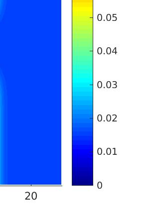
39 Figure 0: Comparison of data time series (red) and numerical (blue) at wave gauges W G 1 W G W G 3 W G Circular dam-break In this D-test case we consider a circular dam-break problem in the [ 5 5] [ 5 5] domain. The depth function is H(x y) = 1 0.5e x y and the initial condition is h 0 (x y) { Ui 0 (x y) = 0 h 0 H(x y) if x + y (x y) = 0.5 H(x y) otherwise. 0 The goal of this numerical test is to compare the execution times in seconds for the SWE and non-hydrostatic GPU codes for different mesh sizes. Simulations are carried out in the time interval [0 1]. The CFL parameter is set to 0.9 and open boundary conditions are considered. 39
40 Table shows execution times for both double precision CUDA codes. Different parameters of ɛ { } were taken into account where ɛ was defined in (3). Figure () shows the results with the different tolerance parameter ɛ. We would like to stress that no big differences are observed for the range of values considered for the tolerance parameter. Figure 1 shows the speedup achieved using a GPU implementation on a GTX Titan Black with respect to a sequential CPU version of the code. We remark a gain in performance greater than 110. Runtime (s) Number of Volumes SWE Non-Hydrostatic ɛ = 10 3 ɛ = 10 4 ɛ = Table : Execution times in sec for SWE and NH GPU implementations Figure 1: Speedup with respect to a CPU-sequential version of the code It can be stated thus that the scheme presented here is efficient and can model dispersive effects with a moderate computational cost. To our 40
Non-Hydrostatic Pressure Shallow Flows: GPU Implementation Using Finite-Volume and Finite-Difference Scheme.
 arxiv:176.4551v1 [math.na] 14 Jun 17 Non-Hydrostatic Pressure Shallow Flows: GPU Implementation Using Finite-Volume and Finite-Difference Scheme. C. Escalante 1 T. Morales de Luna and M.J. Castro 1 1 Departamento
Well-balanced shock-capturing hybrid finite volume-finite difference schemes for Boussinesq-type models
 NUMAN 2010 Well-balanced shock-capturing hybrid finite volume-finite difference schemes for Boussinesq-type models Maria Kazolea 1 Argiris I. Delis 2 1 Environmental Engineering Department, TUC, Greece
B O S Z. - Boussinesq Ocean & Surf Zone model - International Research Institute of Disaster Science (IRIDeS), Tohoku University, JAPAN
, Tohoku University, JAPAN") B O S Z - Boussinesq Ocean & Surf Zone model - Volker Roeber 1 Troy W. Heitmann 2, Kwok Fai Cheung 2, Gabriel C. David 3, Jeremy D. Bricker 1 1 International Research Institute of Disaster Science (IRIDeS),
B O S Z - Boussinesq Ocean & Surf Zone model - Volker Roeber 1 Troy W. Heitmann 2, Kwok Fai Cheung 2, Gabriel C. David 3, Jeremy D. Bricker 1 1 International Research Institute of Disaster Science (IRIDeS),
Alongshore Momentum Balance: Currents
 Chapter 16 Alongshore Momentum Balance: Currents Two assumptions are necessary to get a simple equation for v. The first is that the flow is steady so that time derivatives can be neglected. Second, assume
Numerical methods for the Navier- Stokes equations
 Numerical methods for the Navier- Stokes equations Hans Petter Langtangen 1,2 1 Center for Biomedical Computing, Simula Research Laboratory 2 Department of Informatics, University of Oslo Dec 6, 2012 Note:
A Multiphysics Strategy for Free Surface Flows
 A Multiphysics Strategy for Free Surface Flows Edie Miglio, Simona Perotto, and Fausto Saleri MOX, Modeling and Scientific Computing, Department of Mathematics, Politecnico of Milano, via Bonardi 9, I-133
Comparison of cell-centered and node-centered formulations of a high-resolution well-balanced finite volume scheme: application to shallow water flows
 Comparison of cell-centered and node-centered formulations of a high-resolution well-balanced finite volume scheme: application to shallow water flows Dr Argiris I. Delis Dr Ioannis K. Nikolos (TUC) Maria
3 where g is gravity. S o and S f are bed slope and friction slope at x and y direction, respectively. Here, friction slope is calculated based on Man
 東北地域災害科学研究第 48 巻 () 3 D FORCE MUSCL SCHEME FOR SIMULATING BREAKING SOLITARY WAVE RUNUP Mohammad Bagus Adityawan * Hitoshi Tanaka ABSTRACT Breaking wave simulation using depth averaged based model, i.e.
Project 4: Navier-Stokes Solution to Driven Cavity and Channel Flow Conditions
 Project 4: Navier-Stokes Solution to Driven Cavity and Channel Flow Conditions R. S. Sellers MAE 5440, Computational Fluid Dynamics Utah State University, Department of Mechanical and Aerospace Engineering
30 crete maximum principle, which all imply the bound-preserving property. But most
 3 4 7 8 9 3 4 7 A HIGH ORDER ACCURATE BOUND-PRESERVING COMPACT FINITE DIFFERENCE SCHEME FOR SCALAR CONVECTION DIFFUSION EQUATIONS HAO LI, SHUSEN XIE, AND XIANGXIONG ZHANG Abstract We show that the classical
Modeling and simulation of bedload transport with viscous effects
 Introduction Modeling and simulation of bedload transport with viscous effects E. Audusse, L. Boittin, M. Parisot, J. Sainte-Marie Project-team ANGE, Inria; CEREMA; LJLL, UPMC Université Paris VI; UMR
AA214B: NUMERICAL METHODS FOR COMPRESSIBLE FLOWS
 AA214B: NUMERICAL METHODS FOR COMPRESSIBLE FLOWS 1 / 43 AA214B: NUMERICAL METHODS FOR COMPRESSIBLE FLOWS Treatment of Boundary Conditions These slides are partially based on the recommended textbook: Culbert
Finite Volume Schemes: an introduction
 Finite Volume Schemes: an introduction First lecture Annamaria Mazzia Dipartimento di Metodi e Modelli Matematici per le Scienze Applicate Università di Padova mazzia@dmsa.unipd.it Scuola di dottorato
1 Introduction. J.-L. GUERMOND and L. QUARTAPELLE 1 On incremental projection methods
 J.-L. GUERMOND and L. QUARTAPELLE 1 On incremental projection methods 1 Introduction Achieving high order time-accuracy in the approximation of the incompressible Navier Stokes equations by means of fractional-step
GFD 2013 Lecture 4: Shallow Water Theory
 GFD 213 Lecture 4: Shallow Water Theory Paul Linden; notes by Kate Snow and Yuki Yasuda June 2, 214 1 Validity of the hydrostatic approximation In this lecture, we extend the theory of gravity currents
NUMERICAL SIMULATION OF LONG WAVE RUNUP ON A SLOPING BEACH*
 NUMERICAL SIMULATION OF LONG WAVE RUNUP ON A SLOPING BEACH* * presented at Long Waves Symposium (in parallel with the XXX IAHR Congress) August 5-7, 003, AUTh, Thessaloniki, Greece. by HAKAN I. TARMAN
Riemann Solvers and Numerical Methods for Fluid Dynamics
 Eleuterio R Toro Riemann Solvers and Numerical Methods for Fluid Dynamics A Practical Introduction With 223 Figures Springer Table of Contents Preface V 1. The Equations of Fluid Dynamics 1 1.1 The Euler
GENERAL SOLUTIONS FOR THE INITIAL RUN-UP OF A BREAKING TSUNAMI FRONT
 International Symposium Disaster Reduction on Coasts Scientific-Sustainable-Holistic-Accessible 14 16 November 2005 Monash University, Melbourne, Australia GENERAL SOLUTIONS FOR THE INITIAL RUN-UP OF A
Earth System Modeling Domain decomposition
 Earth System Modeling Domain decomposition Graziano Giuliani International Centre for Theorethical Physics Earth System Physics Section Advanced School on Regional Climate Modeling over South America February
Scientific Computing I
 Scientific Computing I Module 10: Case Study Computational Fluid Dynamics Michael Bader Winter 2012/2013 Module 10: Case Study Computational Fluid Dynamics, Winter 2012/2013 1 Fluid mechanics as a Discipline
Open boundary conditions in numerical simulations of unsteady incompressible flow
 Open boundary conditions in numerical simulations of unsteady incompressible flow M. P. Kirkpatrick S. W. Armfield Abstract In numerical simulations of unsteady incompressible flow, mass conservation can
arxiv: v1 [math.na] 27 Jun 2017
![arxiv: v1 [math.na] 27 Jun 2017](/thumbs/95/123530526.jpg "arxiv: v1 [math.na] 27 Jun 2017") Behaviour of the Serre Equations in the Presence of Steep Gradients Revisited J.P.A. Pitt a,, C. Zoppou a, S.G. Roberts a arxiv:706.08637v [math.na] 27 Jun 207 a Mathematical Sciences Institute, Australian
Behaviour of the Serre Equations in the Presence of Steep Gradients Revisited J.P.A. Pitt a,, C. Zoppou a, S.G. Roberts a arxiv:706.08637v [math.na] 27 Jun 207 a Mathematical Sciences Institute, Australian
Experience with DNS of particulate flow using a variant of the immersed boundary method
 Experience with DNS of particulate flow using a variant of the immersed boundary method Markus Uhlmann Numerical Simulation and Modeling Unit CIEMAT Madrid, Spain ECCOMAS CFD 2006 Motivation wide range
Chapter 2 Finite-Difference Discretization of the Advection-Diffusion Equation
 Chapter Finite-Difference Discretization of the Advection-Diffusion Equation. Introduction Finite-difference methods are numerical methods that find solutions to differential equations using approximate
Advection / Hyperbolic PDEs. PHY 604: Computational Methods in Physics and Astrophysics II
 Advection / Hyperbolic PDEs Notes In addition to the slides and code examples, my notes on PDEs with the finite-volume method are up online: https://github.com/open-astrophysics-bookshelf/numerical_exercises
Pressure corrected SPH for fluid animation
 Pressure corrected SPH for fluid animation Kai Bao, Hui Zhang, Lili Zheng and Enhua Wu Analyzed by Po-Ram Kim 2 March 2010 Abstract We present pressure scheme for the SPH for fluid animation In conventional
Faster Kinetics: Accelerate Your Finite-Rate Combustion Simulation with GPUs
 Faster Kinetics: Accelerate Your Finite-Rate Combustion Simulation with GPUs Christopher P. Stone, Ph.D. Computational Science and Engineering, LLC Kyle Niemeyer, Ph.D. Oregon State University 2 Outline
Two-layer shallow water system and its applications
 Proceedings of Symposia in Applied Mathematics Two-layer shallow water system and its applications Jihwan Kim and Randall J. LeVeque Abstract. The multi-layer shallow water system is derived by depth averaging
MASSACHUSETTS INSTITUTE OF TECHNOLOGY DEPARTMENT OF MECHANICAL ENGINEERING CAMBRIDGE, MASSACHUSETTS NUMERICAL FLUID MECHANICS FALL 2011
 MASSACHUSETTS INSTITUTE OF TECHNOLOGY DEPARTMENT OF MECHANICAL ENGINEERING CAMBRIDGE, MASSACHUSETTS 02139 2.29 NUMERICAL FLUID MECHANICS FALL 2011 QUIZ 2 The goals of this quiz 2 are to: (i) ask some general
Two-waves PVM-WAF method for non-conservative systems
 Two-waves PVM-WAF method for non-conservative systems Manuel J. Castro Díaz 1, E.D Fernández Nieto, Gladys Narbona Reina and Marc de la Asunción 1 1 Departamento de Análisis Matemático University of Málaga
Game Physics. Game and Media Technology Master Program - Utrecht University. Dr. Nicolas Pronost
 Game and Media Technology Master Program - Utrecht University Dr. Nicolas Pronost Soft body physics Soft bodies In reality, objects are not purely rigid for some it is a good approximation but if you hit
Chapter 2. General concepts. 2.1 The Navier-Stokes equations
 Chapter 2 General concepts 2.1 The Navier-Stokes equations The Navier-Stokes equations model the fluid mechanics. This set of differential equations describes the motion of a fluid. In the present work
Cranfield ^91. College of Aeronautics Report No.9007 March The Dry-Bed Problem in Shallow-Water Flows. E F Toro
 Cranfield ^91 College of Aeronautics Report No.9007 March 1990 The Dry-Bed Problem in Shallow-Water Flows E F Toro College of Aeronautics Cranfield Institute of Technology Cranfield. Bedford MK43 OAL.
Bottom friction effects on linear wave propagation
 Bottom friction effects on linear wave propagation G. Simarro a,, A. Orfila b, A. Galán a,b, G. Zarruk b. a E.T.S.I. Caminos, Canales y Puertos, Universidad de Castilla La Mancha. 13071 Ciudad Real, Spain.
Diffusion / Parabolic Equations. PHY 688: Numerical Methods for (Astro)Physics
Physics") Diffusion / Parabolic Equations Summary of PDEs (so far...) Hyperbolic Think: advection Real, finite speed(s) at which information propagates carries changes in the solution Second-order explicit methods
Diffusion / Parabolic Equations Summary of PDEs (so far...) Hyperbolic Think: advection Real, finite speed(s) at which information propagates carries changes in the solution Second-order explicit methods
Colloquium FLUID DYNAMICS 2012 Institute of Thermomechanics AS CR, v.v.i., Prague, October 24-26, 2012 p.
 Colloquium FLUID DYNAMICS 212 Institute of Thermomechanics AS CR, v.v.i., Prague, October 24-26, 212 p. ON A COMPARISON OF NUMERICAL SIMULATIONS OF ATMOSPHERIC FLOW OVER COMPLEX TERRAIN T. Bodnár, L. Beneš
TIME DOMAIN COMPARISONS OF MEASURED AND SPECTRALLY SIMULATED BREAKING WAVES
 TIME DOMAIN COMPARISONS OF MEASRED AND SPECTRAY SIMATED BREAKING WAVES Mustafa Kemal Özalp 1 and Serdar Beji 1 For realistic wave simulations in the nearshore zone besides nonlinear interactions the dissipative
Computation of Incompressible Flows: SIMPLE and related Algorithms
 Computation of Incompressible Flows: SIMPLE and related Algorithms Milovan Perić CoMeT Continuum Mechanics Technologies GmbH milovan@continuummechanicstechnologies.de SIMPLE-Algorithm I - - - Consider
1.1 Implicit solution for vertical viscosity and diffusion terms using finite differences
 1 Vertical viscosity and diffusion operators in ROMS The purpose of this document is to provide sufficient technical detail for the implicit solvers in ROMS code. Although the mathematical concepts are
A Hybrid Method for the Wave Equation. beilina
 A Hybrid Method for the Wave Equation http://www.math.unibas.ch/ beilina 1 The mathematical model The model problem is the wave equation 2 u t 2 = (a 2 u) + f, x Ω R 3, t > 0, (1) u(x, 0) = 0, x Ω, (2)
Divergence Formulation of Source Term
 Preprint accepted for publication in Journal of Computational Physics, 2012 http://dx.doi.org/10.1016/j.jcp.2012.05.032 Divergence Formulation of Source Term Hiroaki Nishikawa National Institute of Aerospace,
Chapter 1 Direct Modeling for Computational Fluid Dynamics
 Chapter 1 Direct Modeling for Computational Fluid Dynamics Computational fluid dynamics (CFD) is a scientific discipline, which aims to capture fluid motion in a discretized space. The description of the
2017 年環境流體力學短期講座 Short Course on Environmental Flows
 2017 年環境流體力學短期講座 Short Course on Environmental Flows 數學 海浪 與沿海動態過程 Mathematics, ocean waves and coastal dynamic processes Philip L-F. Liu National University of Singapore Cornell University September 2017
Linear Hyperbolic Systems
 Linear Hyperbolic Systems Professor Dr E F Toro Laboratory of Applied Mathematics University of Trento, Italy eleuterio.toro@unitn.it http://www.ing.unitn.it/toro October 8, 2014 1 / 56 We study some basic
Calculating Storm Surge and Other Coastal Hazards Using Geoclaw
 Calculating Storm Surge and Other Coastal Hazards Using Geoclaw Kyle T. Mandli Department of Applied Mathematics University of Washington Seattle, WA, USA Modeling and Computations of Shallow-Water Coastal
BOUSSINESQ-TYPE EQUATIONS WITH VARIABLE COEFFICIENTS FOR NARROW-BANDED WAVE PROPAGATION FROM ARBITRARY DEPTHS TO SHALLOW WATERS
 BOUSSINESQ-TYPE EQUATIONS WITH VARIABLE COEFFICIENTS FOR NARROW-BANDED WAVE PROPAGATION FROM ARBITRARY DEPTHS TO SHALLOW WATERS Gonzalo Simarro 1, Alvaro Galan, Alejandro Orfila 3 A fully nonlinear Boussinessq-type
Block-Structured Adaptive Mesh Refinement
 Block-Structured Adaptive Mesh Refinement Lecture 2 Incompressible Navier-Stokes Equations Fractional Step Scheme 1-D AMR for classical PDE s hyperbolic elliptic parabolic Accuracy considerations Bell
Basic Aspects of Discretization
 Basic Aspects of Discretization Solution Methods Singularity Methods Panel method and VLM Simple, very powerful, can be used on PC Nonlinear flow effects were excluded Direct numerical Methods (Field Methods)
Finite Differences for Differential Equations 28 PART II. Finite Difference Methods for Differential Equations
 Finite Differences for Differential Equations 28 PART II Finite Difference Methods for Differential Equations Finite Differences for Differential Equations 29 BOUNDARY VALUE PROBLEMS (I) Solving a TWO
The shallow water equations Lecture 8. (photo due to Clark Little /SWNS)
") The shallow water equations Lecture 8 (photo due to Clark Little /SWNS) The shallow water equations This lecture: 1) Derive the shallow water equations 2) Their mathematical structure 3) Some consequences
The shallow water equations Lecture 8 (photo due to Clark Little /SWNS) The shallow water equations This lecture: 1) Derive the shallow water equations 2) Their mathematical structure 3) Some consequences
We briefly discuss two examples for solving wave propagation type problems with finite differences, the acoustic and the seismic problem.
 Excerpt from GEOL557 Numerical Modeling of Earth Systems by Becker and Kaus 2016 1 Wave propagation Figure 1: Finite difference discretization of the 2D acoustic problem. We briefly discuss two examples
Time stepping methods
 Time stepping methods ATHENS course: Introduction into Finite Elements Delft Institute of Applied Mathematics, TU Delft Matthias Möller (m.moller@tudelft.nl) 19 November 2014 M. Möller (DIAM@TUDelft) Time
Sung-Ik Sohn and Jun Yong Shin
 Commun. Korean Math. Soc. 17 (2002), No. 1, pp. 103 120 A SECOND ORDER UPWIND METHOD FOR LINEAR HYPERBOLIC SYSTEMS Sung-Ik Sohn and Jun Yong Shin Abstract. A second order upwind method for linear hyperbolic
Elliptic Problems / Multigrid. PHY 604: Computational Methods for Physics and Astrophysics II
 Elliptic Problems / Multigrid Summary of Hyperbolic PDEs We looked at a simple linear and a nonlinear scalar hyperbolic PDE There is a speed associated with the change of the solution Explicit methods
Dedicated to the 70th birthday of Professor Lin Qun
 Journal of Computational Mathematics, Vol.4, No.3, 6, 39 5. ANTI-DIFFUSIVE FINITE DIFFERENCE WENO METHODS FOR SHALLOW WATER WITH TRANSPORT OF POLLUTANT ) Zhengfu Xu (Department of Mathematics, Pennsylvania
A well-balanced scheme for the shallow-water equations with topography or Manning friction.
 A well-balanced scheme for the shallow-water equations with topography or Manning friction. Victor Michel-Dansac a,, Christophe Berthon a, Stéphane Clain b, Françoise Foucher a,c a Laboratoire de Mathématiques
PDE Solvers for Fluid Flow
 PDE Solvers for Fluid Flow issues and algorithms for the Streaming Supercomputer Eran Guendelman February 5, 2002 Topics Equations for incompressible fluid flow 3 model PDEs: Hyperbolic, Elliptic, Parabolic
The Shallow Water Equations
 If you have not already done so, you are strongly encouraged to read the companion file on the non-divergent barotropic vorticity equation, before proceeding to this shallow water case. We do not repeat
A High-Order Discontinuous Galerkin Method for the Unsteady Incompressible Navier-Stokes Equations
 A High-Order Discontinuous Galerkin Method for the Unsteady Incompressible Navier-Stokes Equations Khosro Shahbazi 1, Paul F. Fischer 2 and C. Ross Ethier 1 1 University of Toronto and 2 Argonne National
Validation of an Entropy-Viscosity Model for Large Eddy Simulation
 Validation of an Entropy-Viscosity Model for Large Eddy Simulation J.-L. Guermond, A. Larios and T. Thompson 1 Introduction A primary mainstay of difficulty when working with problems of very high Reynolds
Available online at Eng. Math. Lett. 2014, 2014:17 ISSN: WAVE ATTENUATION OVER A SUBMERGED POROUS MEDIA I.
 Available online at http://scik.org Eng. Math. Lett. 04, 04:7 ISSN: 049-9337 WAVE ATTENUATION OVER A SUBMERGED POROUS MEDIA I. MAGDALENA Industrial and Financial Mathematics Research Group, Faculty of
CHAPTER 7 SEVERAL FORMS OF THE EQUATIONS OF MOTION
 CHAPTER 7 SEVERAL FORMS OF THE EQUATIONS OF MOTION 7.1 THE NAVIER-STOKES EQUATIONS Under the assumption of a Newtonian stress-rate-of-strain constitutive equation and a linear, thermally conductive medium,
2. FLUID-FLOW EQUATIONS SPRING 2019
 2. FLUID-FLOW EQUATIONS SPRING 2019 2.1 Introduction 2.2 Conservative differential equations 2.3 Non-conservative differential equations 2.4 Non-dimensionalisation Summary Examples 2.1 Introduction Fluid
Self-similar solutions for the diffraction of weak shocks
 Self-similar solutions for the diffraction of weak shocks Allen M. Tesdall John K. Hunter Abstract. We numerically solve a problem for the unsteady transonic small disturbance equations that describes
7 Hyperbolic Differential Equations
 Numerical Analysis of Differential Equations 243 7 Hyperbolic Differential Equations While parabolic equations model diffusion processes, hyperbolic equations model wave propagation and transport phenomena.
Modified Serre Green Naghdi equations with improved or without dispersion
 Modified Serre Green Naghdi equations with improved or without dispersion DIDIER CLAMOND Université Côte d Azur Laboratoire J. A. Dieudonné Parc Valrose, 06108 Nice cedex 2, France didier.clamond@gmail.com
The Lattice Boltzmann method for hyperbolic systems. Benjamin Graille. October 19, 2016
 The Lattice Boltzmann method for hyperbolic systems Benjamin Graille October 19, 2016 Framework The Lattice Boltzmann method 1 Description of the lattice Boltzmann method Link with the kinetic theory Classical
Chapter 5 HIGH ACCURACY CUBIC SPLINE APPROXIMATION FOR TWO DIMENSIONAL QUASI-LINEAR ELLIPTIC BOUNDARY VALUE PROBLEMS
 Chapter 5 HIGH ACCURACY CUBIC SPLINE APPROXIMATION FOR TWO DIMENSIONAL QUASI-LINEAR ELLIPTIC BOUNDARY VALUE PROBLEMS 5.1 Introduction When a physical system depends on more than one variable a general
Accuracy-Preserving Source Term Quadrature for Third-Order Edge-Based Discretization
 Preprint accepted in Journal of Computational Physics. https://doi.org/0.06/j.jcp.07.04.075 Accuracy-Preserving Source Term Quadrature for Third-Order Edge-Based Discretization Hiroaki Nishikawa and Yi
Numerical accuracy in the solution of the shallow-water equations
 Numerical accuracy in the solution of the shallow-water equations P. Broomans & C. Vuik Delft University of Technology, Delft, Netherlands A.E. Mynett & J. Mooiman WL Delft Hydraulics, Delft, Netherlands
Strongly nonlinear long gravity waves in uniform shear flows
 Strongly nonlinear long gravity waves in uniform shear flows Wooyoung Choi Department of Naval Architecture and Marine Engineering, University of Michigan, Ann Arbor, Michigan 48109, USA Received 14 January
Solution Methods. Steady State Diffusion Equation. Lecture 04
 Solution Methods Steady State Diffusion Equation Lecture 04 1 Solution methods Focus on finite volume method. Background of finite volume method. Discretization example. General solution method. Convergence.
Salmon: Introduction to ocean waves
 9 The shallow-water equations. Tsunamis. Our study of waves approaching the beach had stopped at the point of wave breaking. At the point of wave breaking, the linear theory underlying Propositions #1
Introduction to Partial Differential Equations
 Introduction to Partial Differential Equations Partial differential equations arise in a number of physical problems, such as fluid flow, heat transfer, solid mechanics and biological processes. These
Dynamics of the Ems Estuary
 Dynamics of the Ems Estuary Physics of coastal systems Jerker Menninga 0439738 Utrecht University Institute for Marine and Atmospheric research Utrecht Lecturer: Prof. dr. H.E. de Swart Abstract During
Mathematical and computational modeling for the generation and propagation of waves in marine and coastal environments
 Mathematical and computational modeling for the generation and propagation of waves in marine and coastal environments Maria Kazolea School of Environmental Engineering Technical University of Crete September
NONLINEAR FEATURES IN EXPLICIT ALGEBRAIC MODELS FOR TURBULENT FLOWS WITH ACTIVE SCALARS
 June - July, 5 Melbourne, Australia 9 7B- NONLINEAR FEATURES IN EXPLICIT ALGEBRAIC MODELS FOR TURBULENT FLOWS WITH ACTIVE SCALARS Werner M.J. Lazeroms () Linné FLOW Centre, Department of Mechanics SE-44
Zonal modelling approach in aerodynamic simulation
 Zonal modelling approach in aerodynamic simulation and Carlos Castro Barcelona Supercomputing Center Technical University of Madrid Outline 1 2 State of the art Proposed strategy 3 Consistency Stability
Application of the relaxat ion met hod to model hydraulic jumps
 Application of the relaxat ion met hod to model hydraulic jumps P. J. Montgomery Mathematics and Computer Science Program, University of Northern British Columbia, Prince George, Canada. Abstract A finite
Numerical Solution Techniques in Mechanical and Aerospace Engineering
 Numerical Solution Techniques in Mechanical and Aerospace Engineering Chunlei Liang LECTURE 3 Solvers of linear algebraic equations 3.1. Outline of Lecture Finite-difference method for a 2D elliptic PDE
Two-Dimensional Unsteady Flow in a Lid Driven Cavity with Constant Density and Viscosity ME 412 Project 5
 Two-Dimensional Unsteady Flow in a Lid Driven Cavity with Constant Density and Viscosity ME 412 Project 5 Jingwei Zhu May 14, 2014 Instructor: Surya Pratap Vanka 1 Project Description The objective of
FDM for parabolic equations
 FDM for parabolic equations Consider the heat equation where Well-posed problem Existence & Uniqueness Mass & Energy decreasing FDM for parabolic equations CNFD Crank-Nicolson + 2 nd order finite difference
Depth-integrated, non-hydrostatic model for wave breaking and run-up
 INTERNATIONAL JOURNAL FOR NUMERICAL METHODS IN FLUIDS Int. J. Numer. Meth. Fluids (8) Published online in Wiley InterScience (www.interscience.wiley.com). DOI: 1.1/fld.19 Depth-integrated, non-hydrostatic
Turbulent Boundary Layers & Turbulence Models. Lecture 09
 Turbulent Boundary Layers & Turbulence Models Lecture 09 The turbulent boundary layer In turbulent flow, the boundary layer is defined as the thin region on the surface of a body in which viscous effects
Study of Forced and Free convection in Lid driven cavity problem
 MIT Study of Forced and Free convection in Lid driven cavity problem 18.086 Project report Divya Panchanathan 5-11-2014 Aim To solve the Navier-stokes momentum equations for a lid driven cavity problem
HIGH-ORDER ACCURATE METHODS BASED ON DIFFERENCE POTENTIALS FOR 2D PARABOLIC INTERFACE MODELS
 HIGH-ORDER ACCURATE METHODS BASED ON DIFFERENCE POTENTIALS FOR 2D PARABOLIC INTERFACE MODELS JASON ALBRIGHT, YEKATERINA EPSHTEYN, AND QING XIA Abstract. Highly-accurate numerical methods that can efficiently
General Curvilinear Ocean Model (GCOM): Enabling Thermodynamics
: Enabling Thermodynamics") General Curvilinear Ocean Model (GCOM): Enabling Thermodynamics M. Abouali, C. Torres, R. Walls, G. Larrazabal, M. Stramska, D. Decchis, and J.E. Castillo AP0901 09 General Curvilinear Ocean Model (GCOM):
General Curvilinear Ocean Model (GCOM): Enabling Thermodynamics M. Abouali, C. Torres, R. Walls, G. Larrazabal, M. Stramska, D. Decchis, and J.E. Castillo AP0901 09 General Curvilinear Ocean Model (GCOM):
12 The Heat equation in one spatial dimension: Simple explicit method and Stability analysis
 ATH 337, by T. Lakoba, University of Vermont 113 12 The Heat equation in one spatial dimension: Simple explicit method and Stability analysis 12.1 Formulation of the IBVP and the minimax property of its
An Overview of Fluid Animation. Christopher Batty March 11, 2014
 An Overview of Fluid Animation Christopher Batty March 11, 2014 What distinguishes fluids? What distinguishes fluids? No preferred shape. Always flows when force is applied. Deforms to fit its container.
DYNAMICS OF LIQUEFIED SEDIMENT FLOW. Advances in Natural and Technological Hazards Research Vol. 19
 DYNAMICS OF LIQUEFIED SEDIMENT FLOW Advances in Natural and Technological Hazards Research Vol. 9 THE DYNAMICS OF LIQUEFIED SEDIMENT FLOW UNDERGOING PROGRESSIVE SOLIDIFICATION S. SASSA Disaster Prevention
A note on accurate and efficient higher order Galerkin time stepping schemes for the nonstationary Stokes equations
 A note on accurate and efficient higher order Galerkin time stepping schemes for the nonstationary Stokes equations S. Hussain, F. Schieweck, S. Turek Abstract In this note, we extend our recent work for
Machine Learning Applied to 3-D Reservoir Simulation
 Machine Learning Applied to 3-D Reservoir Simulation Marco A. Cardoso 1 Introduction The optimization of subsurface flow processes is important for many applications including oil field operations and
2.2. Methods for Obtaining FD Expressions. There are several methods, and we will look at a few:
 .. Methods for Obtaining FD Expressions There are several methods, and we will look at a few: ) Taylor series expansion the most common, but purely mathematical. ) Polynomial fitting or interpolation the
A semi-implicit non-hydrostatic covariant dynamical kernel using spectral representation in the horizontal and a height based vertical coordinate
 A semi-implicit non-hydrostatic covariant dynamical kernel using spectral representation in the horizontal and a height based vertical coordinate Juan Simarro and Mariano Hortal AEMET Agencia Estatal de
Flood Routing by the Non-Linear Muskingum Model: Conservation of Mass and Momentum
 Archives of Hydro-Engineering and Environmental Mechanics Vol. 56 (29), No. 3 4, pp. 121 137 IBW PAN, ISSN 1231 3726 Flood Routing by the Non-Linear Muskingum Model: Conservation of Mass and Momentum Dariusz
Additive Manufacturing Module 8
 Additive Manufacturing Module 8 Spring 2015 Wenchao Zhou zhouw@uark.edu (479) 575-7250 The Department of Mechanical Engineering University of Arkansas, Fayetteville 1 Evaluating design https://www.youtube.com/watch?v=p
Lattice Boltzmann Method
 3 Lattice Boltzmann Method 3.1 Introduction The lattice Boltzmann method is a discrete computational method based upon the lattice gas automata - a simplified, fictitious molecular model. It consists of
6. Iterative Methods for Linear Systems. The stepwise approach to the solution...
 6 Iterative Methods for Linear Systems The stepwise approach to the solution Miriam Mehl: 6 Iterative Methods for Linear Systems The stepwise approach to the solution, January 18, 2013 1 61 Large Sparse
EINDHOVEN UNIVERSITY OF TECHNOLOGY Department of Mathematics and Computer Science. CASA-Report March2008
 EINDHOVEN UNIVERSITY OF TECHNOLOGY Department of Mathematics and Computer Science CASA-Report 08-08 March2008 The complexe flux scheme for spherically symmetrie conservation laws by J.H.M. ten Thije Boonkkamp,
ESS Turbulence and Diffusion in the Atmospheric Boundary-Layer : Winter 2017: Notes 1
 ESS5203.03 - Turbulence and Diffusion in the Atmospheric Boundary-Layer : Winter 2017: Notes 1 Text: J.R.Garratt, The Atmospheric Boundary Layer, 1994. Cambridge Also some material from J.C. Kaimal and