Physical Modelling with Simscape Rick Hyde
|
|
|
- Calvin Simmons
- 5 years ago
- Views:
Transcription

1 Physical Modelling with Simscape Rick Hyde The MathWorks, Inc.
2 Outline Part 1: Introduction to Simscape Review approaches to modelling Overview of Simscape-based libraries Introduction to physical networks Simscape tutorial: DC motor Part 2: Application examples PMSM and drive Landing gear extension/retraction Engine cooling system 2


3 Designing physical systems Multi-domain Mechanical Electrical R 6 5 Hydraulic/pneumatic Thermal Modelling environment Multi-domain Mix with algorithms/control Multiple levels of fidelity Optimization tools Code generation 3

4 Data-driven versus physics-based modelling Data sources Data-driven Experimental data External tool (complexityreduction exercise) Complex behaviour with many unknowns Examples Combustion engine Aerodynamics Physics-based Mathematical paradigms ODEs & DAEs State charts Physical networks Behaviour is adequately approximated by limited set of equations Examples Algorithms/control Gears & clutches E( x, ) x f ( x, u, ) 4
 Single body motion")
 Simscape extension Equation set E( x, ) x f ( x, u,")

5 Extending Simulink using Simscape Equation set x Simulink f Explicit equation Relevance e ( x, u, ) Single body motion Multiple-body motion when there is compliance Most algorithms (control) Simscape extension Equation set E( x, ) x f ( x, u, ) Implicit equation Relevance 1-D multi-body systems e.g. drivelines Electrical networks Hydraulic/pneumatic networks s1 s2 s3 5
6 What does this model represent? 6
7 What does this model represent? 7
8 Modelling an electrical circuit in Simulink Step 1: figure out the equations Step 2: build the model 8
9 Modelling an electrical circuit in Simscape Build the model 9
10 Modelling an electrical circuit in Simscape Component equations from library blocks Additional constraints from circuit topology 11
11 Algebraic loops in Simscape Simscape converts entire network to equations and solves them simultaneously, so it intrinsically solves algebraic loops. 12

12 Signal-based modelling methods pose challenges Very flexible, but can be difficult to use efficiently Requires expertise in several areas Physics, math, programming Deriving system level equations is difficult and error prone Resulting model can be difficult to read and maintain 13
13 Physical modelling methods ideal for plant models Build accurate models quickly System-level equations derived automatically Model is easier to read Reflects structure of system Easier to update model New technologies or designs can be easily incorporated into the model 14


14 SimPowerSystems SimMechanics SimHydraulics SimDriveline SimElectronics Simscape libraries Simscape MATLAB, Simulink 15
15 Extensive Component Libraries SimElectronics > 90 component models Actuators, drivers Sensors Semiconductors Integrated circuits Models look like schematics Easy to read and interpret 16


16 Generate Code Use Simulink Coder to convert models into C code Share with other users (Model Reference) Protect intellectual property u u s1 s2 s3 Controller s1 s2 s3 Plant.DLL (Simulink) Model Reference Protected Mode Alternative: ssc_protect Run hardware-in-the-loop simulations u s1 s2 s3 17
17 Outline Part 1: Introduction to Simscape Review approaches to modelling Overview of Simscape-based libraries Introduction to physical networks Simscape tutorial: DC motor Part 2: Application examples PMSM and drive Landing gear extension/retraction Engine cooling system 18
 at a node is zero Each component must specify an equation involving the through and/or across variables at its")
18 Through & across variables q p 1 p 2 p 1 p 2 p 3 p 4 Abstract to a physical network All nodes have the same pressure (across variable) Sum of flows (through variables) at a node is zero Each component must specify an equation involving the through and/or across variables at its boundary 19
19 Through & across variables by domain Domain Through Across Electrical Current Voltage Hydraulic Flow rate Pressure Rotational mechanical Torque Angular speed Translational mechanical Force Translational speed Pneumatic Mass flow Heat flow Pressure Temperature Magnetic Magnetic flux Magneto motive force Thermal Heat flow Temperature 20
20 Components Domain (across, through) Resistance Inductance Capacitance Electrical (v, i) Resistor Inductor Capacitor Rotational mechanical? Translational mechanical Hydraulic Resistance (R) dissipates power. R=voltage/current (ratio of across to through) 21
21 Components Domain Resistance Inductance Capacitance Electrical (v, i) Resistor Inductor Capacitor Rotational mechanical (w, trq) Rotational damper Translational mechanical Hydraulic 22
22 Components Domain Resistance Inductance Capacitance Electrical (v, i) Resistor Inductor Capacitor Rotational mechanical (w, trq) Rotational damper Translational mechanical (v, F) Hydraulic Translational damper 23
23 Components Domain Resistance Inductance Capacitance Electrical (v, i) Resistor Inductor Capacitor Rotational mechanical (w, trq) Rotational damper Translational mechanical (v, F) Translational damper Hydraulic (p, Q)? 24
24 Components Domain Resistance Inductance Capacitance Electrical (V, i) Resistor Inductor Capacitor Rotational mechanical (w, trq) Rotational damper Translational mechanical (v, F) Hydraulic (p, Q) Translational damper Hydraulic orifice p=kq n 25
25 Components Domain Resistance Inductance Capacitance Electrical (v, i) Resistor Inductor Capacitor Rotational mechanical (w, trq) Rotational damper? Translational mechanical (v, F) Hydraulic (p, Q) Translational damper Hydraulic orifice p=kq n Inductance keeps through variable flowing (current) 26
26 Components Domain Resistance Inductance Capacitance Electrical (v, i) Resistor Inductor Capacitor Rotational mechanical (w, trq) Rotational damper Rotational Spring Translational mechanical (v, F) Hydraulic (p, Q) Translational damper Hydraulic orifice p=kq n Inductance keeps through variable flowing (current) 27
27 Components Domain Resistance Inductance Capacitance Electrical (v, i) Resistor Inductor Capacitor Rotational mechanical (w, trq) Rotational damper Rotational Spring? Translational mechanical (v, F) Translational damper Translational spring Hydraulic (p, Q) Hydraulic orifice p=kq n Accumulator Capacitor maintains across variable (voltage) 28
28 Components Domain Resistance Inductance Capacitance Electrical (v, i) Resistor Inductor Capacitor Rotational mechanical (w, trq) Rotational damper Rotational Spring Inertia Translational mechanical (v, F) Translational damper Translational spring Mass Hydraulic (p, Q) Hydraulic orifice Accumulator Fluid inertia p=kq n Capacitor maintains across variable (voltage) 29


29 The inerter Invented by Prof Malcolm Smith, Cambridge University. Force is proportional to relative acceleration. 30
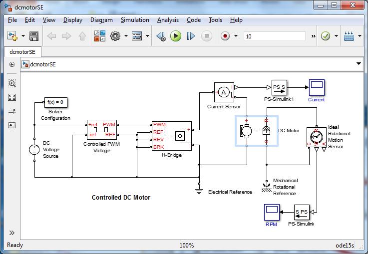
30 Outline Part 1: Introduction to Simscape Review approaches to modelling Overview of Simscape-based libraries Introduction to physical networks Simscape tutorial: DC motor Part 2: Application examples PMSM and drive Landing gear extension/retraction Engine cooling system 31
31 DC Motor: Modelling options 1. Use SimElectronics DC Motor block 2. Build an equivalent circuit using Simscape foundation library 3. Define a custom component using Simscape language Equation-based Composite 32
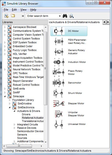
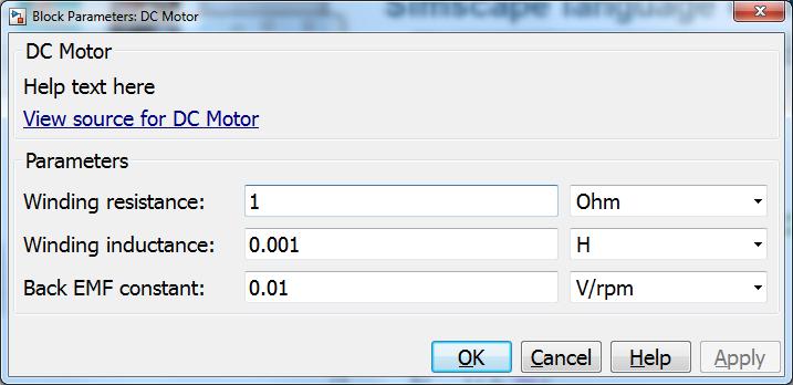
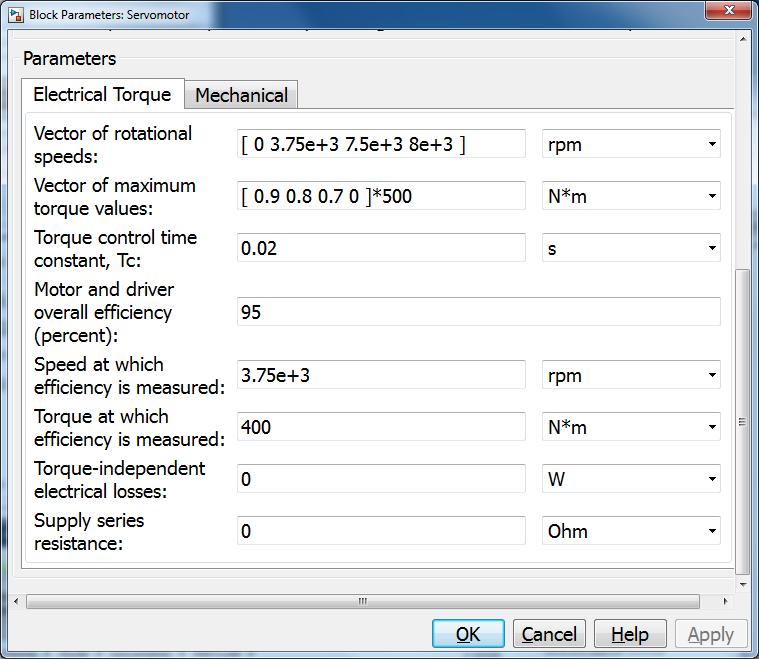
32 SimElectronics pre-built component 33


33 SimElectronics DC motor parameterization options Parameterized according to datasheet standards Multiple methods for assigning parameters Description, functionality and formulation provided in Help dialog 34
34 SimElectronics pre-built component example 35


35 Equivalent circuit based on Simscape foundation library components 36

36 Equation-based Simscape language component 1. Define equations 2. Define ports/connections 3. Define variables 4. Define parameters 5. Write block help 6. Add icon [optional] 7. Publish v = Ri + L di dt + kω 37
37 Equation-based Simscape language example 38
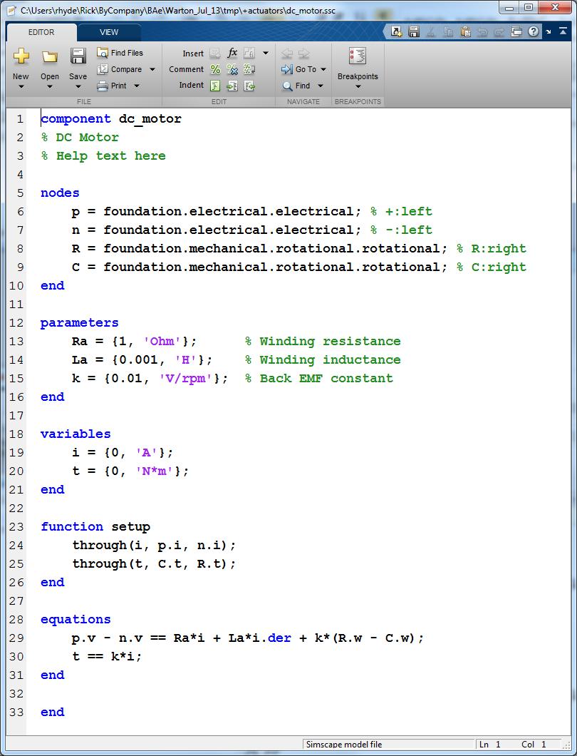
38 Equation-based Simscape language component v = Ri + L di dt + kω τ = ki 39


39 Composite Simscape language component Connect components in Simscape language file Refer to existing components Overwrite parameter values if necessary Connect components 40
40 Outline Part 1: Introduction to Simscape Review approaches to modelling Overview of Simscape-based libraries Introduction to physical networks Simscape tutorial: DC motor Part 2: Application examples PMSM and drive Landing gear extension/retraction Engine cooling system 41
41 PMSM and drive modelling Components PMSM Switching devices (IGBTs) Controller Tools SimPowerSystems System-level to support circuit and controller design SimElectronics Detailed switching device models fine-tuning and losses prediction 42
42 Complexity IGBT modelling I-V characteristic Piecewise linear Lookup table Physics-based Composite/complex Dynamics No dynamics Behavioural Constant capacitance Nonlinear charge model Complexity: Slower simulations, detailed parameterization required Higher-fidelity/better predictions 43
43 Complexity IGBT modelling SimPowerSystems Piecewise linear No dynamics or constant capacitance SimElectronics Nonlinear, physics-based, simple Datasheet parameterization Easily tuneable by optimization SPICE Composite from complex physics-based components Manufacturer NETLIST 44
44 pmsm_drive 45
45 System-level equivalent of PMSM and drive Example pmsm_drive suitable for Component design Electrical system design What about the system designer e.g. for a hybrid vehicle? Model the whole system and predict efficiency/performance Multiple drive cycles HIL test 46
46 Abstracted PMSM drive Energy-based Mechanical power out = power in minus losses Losses (physics-based analysis) Copper losses proportional to the torque Iron losses dependent on voltage and switching frequency Losses (empirical approach) Tabulate as function of torque and speed (and possibly DC volts) Table derived from detailed PMSM and drive model Assume torque is closed-loop controlled 47

47 Abstracted PMSM drive 48
48 sm_landing_gear 49


49 Landing Gear Design Model: Problem: Determine the force required of the hydraulic cylinder to meet system specifications Solution: Use Simulink, SimMechanics, SimHydraulics, and SimElectronics to design the system 50


50 Modeling Thermal Fluid Systems Thermal Liquid Library New domain and library for thermal liquid systems Single-phase liquids Fluid properties vary with temperature Applications Heat exchangers Pipelines 51
51 Engine cooling example 52
52 Challenges in Thermal Fluid Simulation Restrictions on block combinations Some combinations require fluid volumes at nodes Blocks sharing differential variables makes initialization difficult Pneumatic Domain Fluid Volume Volume usually required at node Poor behavior at regime changes, low flow rates, and flow reversals Zero crossing difficulties, solver issues Tube 1 Tube 2 Tube 3 Flow Direction Properties in Tube 2 depend on flow direction 53


53 Addressing challenges with full-flux method Each element contains a volume of fluid No fluid volumes at nodes Control volume approach used in each element Internal nodes defined Network nodes have no differential variables Power flux includes convection+conduction Smooth temperature variation of node temperature at zero flow Heat Mech. Fluid Volume BoundaryA BoundaryB Thermal Fluid Internal Node Thermal Fluid Temp. A Temperature Temp. B Node Temp. Convection dominates Conduction dominates mdot 54
54 Simscape language best practice Build incrementally Write test scripts/harnesses Avoid discontinuities Use appropriate level of fidelity Write out equations for custom blocks before building 55
55 Conclusions Simscape extends Simulink to Support a network approach Create models that topologically match the physical system Create component models by Using ready-made blocks from MathWorks libraries Constructing composite components from Simscape foundation library blocks Writing custom equations in Simscape language All the benefits of Simulink apply e.g. Code generation Tight integration with MATLAB 56
56 LINKS Physical modelling central web-page: Essentials of physical modelling: 57


57 Viewing Simscape Simulations Results ssc_explore Explore simulation results from entire physical network Select multiple signals Overlay or separate plots Arrange plots Extract plot to separate window Spend more time analyzing, less time simulating Download from MATLAB Central 58


58 Zero-Crossing Statistics Log zero-crossing statistics for Simscape networks Shows when ZCs occur Can help indicate location of simulation bottlenecks 59
, mechanical (lower) Primary benefit is to speed-up simulations where fixed-step solvers are required, like HIL Variable step,")
59 Local Solvers Improve Simulation Performance Use fixed-step, implicit solvers locally on Simscape networks Use implicit solvers only where necessary Configure solver per physical network Run different physical networks at different sample rates Electrical (higher), mechanical (lower) Primary benefit is to speed-up simulations where fixed-step solvers are required, like HIL Variable step, implicit (ODE15s) Controller Physical Network Physical Network Fixed step, explicit (ODE1) Local fixed step Fixed-step, implicit (ODE14x) implicit solver #1 Controller Physical Network Physical Network Local fixed step implicit solver #2 Generated Code 60
Mathematical Modelling Using SimScape (Electrical Systems)
") Experiment Three Mathematical Modelling Using SimScape (Electrical Systems) Control Systems Laboratory Dr. Zaer Abo Hammour Dr. Zaer Abo Hammour Control Systems Laboratory 1. Model and simulate MultiDomain
Experiment Three Mathematical Modelling Using SimScape (Electrical Systems) Control Systems Laboratory Dr. Zaer Abo Hammour Dr. Zaer Abo Hammour Control Systems Laboratory 1. Model and simulate MultiDomain
Index. Index. More information. in this web service Cambridge University Press
 A-type elements, 4 7, 18, 31, 168, 198, 202, 219, 220, 222, 225 A-type variables. See Across variable ac current, 172, 251 ac induction motor, 251 Acceleration rotational, 30 translational, 16 Accumulator,
Modeling a powertrain in Simscape in a modular vehicle component model library. Stuttgart, , MBtech, Jörn Bader
 Modeling a powertrain in Simscape in a modular vehicle component model library Stuttgart, 24.09.2015, MBtech, Jörn Bader Contents { Introduction initial situation { Driving performance and consumption
Comparison of Simulation Programs for Supercapacitor Modelling Model Creation and Verification PATRIK JOHANSSON BJÖRN ANDERSSON
 Comparison of Simulation Programs for Supercapacitor Modelling Model Creation and Verification Master of Science Thesis PATRIK JOHANSSON BJÖRN ANDERSSON 180p Electrical Engineering Department of Energy
A system is defined as a combination of components (elements) that act together to perform a certain objective. System dynamics deal with:
 that act together to perform a certain objective. System dynamics deal with:") Chapter 1 Introduction to System Dynamics A. Bazoune 1.1 INTRODUCTION A system is defined as a combination of components (elements) that act together to perform a certain objective. System dynamics deal
Chapter 1 Introduction to System Dynamics A. Bazoune 1.1 INTRODUCTION A system is defined as a combination of components (elements) that act together to perform a certain objective. System dynamics deal
MAS601 Design, Modeling & Simulation. Day 2
 MAS601 Design, Modelling and Simulation of Mechatronic Systems, Semester 2, 2017. Page: 1 MAS601 Design, Modeling & Simulation Day 2 Analysis of causality and handling of algebraic loops to improve simulation
Equivalent Circuits. Henna Tahvanainen. November 4, ELEC-E5610 Acoustics and the Physics of Sound, Lecture 3
 Equivalent Circuits ELEC-E5610 Acoustics and the Physics of Sound, Lecture 3 Henna Tahvanainen Department of Signal Processing and Acoustics Aalto University School of Science and Technology November 4,
2.004 Dynamics and Control II Spring 2008
 MIT OpenCourseWare http://ocwmitedu 00 Dynamics and Control II Spring 00 For information about citing these materials or our Terms of Use, visit: http://ocwmitedu/terms Massachusetts Institute of Technology
Introduction to AC Circuits (Capacitors and Inductors)
") Introduction to AC Circuits (Capacitors and Inductors) Amin Electronics and Electrical Communications Engineering Department (EECE) Cairo University elc.n102.eng@gmail.com http://scholar.cu.edu.eg/refky/
Introduction to AC Circuits (Capacitors and Inductors) Amin Electronics and Electrical Communications Engineering Department (EECE) Cairo University elc.n102.eng@gmail.com http://scholar.cu.edu.eg/refky/
(Refer Slide Time: 00:01:30 min)
") Control Engineering Prof. M. Gopal Department of Electrical Engineering Indian Institute of Technology, Delhi Lecture - 3 Introduction to Control Problem (Contd.) Well friends, I have been giving you various
Control Engineering Prof. M. Gopal Department of Electrical Engineering Indian Institute of Technology, Delhi Lecture - 3 Introduction to Control Problem (Contd.) Well friends, I have been giving you various
MODELING IN XCOS USING MODELICA
 powered by MODELING IN XCOS USING MODELICA In this tutorial we show how to model a physical system described by ODE using the Modelica extensions of the Xcos environment. The same model has been solved
Modeling of Dynamic Systems: Notes on Bond Graphs Version 1.0 Copyright Diane L. Peters, Ph.D., P.E.
 Modeling of Dynamic Systems: Notes on Bond Graphs Version 1.0 Copyright 2015 Diane L. Peters, Ph.D., P.E. Spring 2015 2 Contents 1 Overview of Dynamic Modeling 5 2 Bond Graph Basics 7 2.1 Causality.............................
Lab 3: Quanser Hardware and Proportional Control
 Lab 3: Quanser Hardware and Proportional Control The worst wheel of the cart makes the most noise. Benjamin Franklin 1 Objectives The goal of this lab is to: 1. familiarize you with Quanser s QuaRC tools
Deriving a Fast and Accurate PMSM Motor Model from Finite Element Analysis The MathWorks, Inc. 1
 Deriving a Fast and Accurate PMSM Motor Model from Finite Element Analysis Dakai Hu, Ph.D Haiwei Cai, Ph.D MathWorks Application Engineer ANSYS Application Engineer 2017 The MathWorks, Inc. 1 Motivation
Modeling and Simulation Revision III D R. T A R E K A. T U T U N J I P H I L A D E L P H I A U N I V E R S I T Y, J O R D A N
 Modeling and Simulation Revision III D R. T A R E K A. T U T U N J I P H I L A D E L P H I A U N I V E R S I T Y, J O R D A N 0 1 4 Block Diagrams Block diagram models consist of two fundamental objects:
Lecture 39. PHYC 161 Fall 2016
 Lecture 39 PHYC 161 Fall 016 Announcements DO THE ONLINE COURSE EVALUATIONS - response so far is < 8 % Magnetic field energy A resistor is a device in which energy is irrecoverably dissipated. By contrast,
Lab 1: Dynamic Simulation Using Simulink and Matlab
 Lab 1: Dynamic Simulation Using Simulink and Matlab Objectives In this lab you will learn how to use a program called Simulink to simulate dynamic systems. Simulink runs under Matlab and uses block diagrams
2002 Prentice Hall, Inc. Gene F. Franklin, J. David Powell, Abbas Emami-Naeini Feedback Control of Dynamic Systems, 4e
 u Figure 2.1 Cruise-control model x Friction force bx m x u Figure 2.2 Free-body diagram for cruise control S P 278 Figure 2.3 Automobile suspension y m 2 k s b v car x m 1 k w Road surface r Inertial
ET3-7: Modelling II(V) Electrical, Mechanical and Thermal Systems
 Electrical, Mechanical and Thermal Systems") ET3-7: Modelling II(V) Electrical, Mechanical and Thermal Systems Agenda of the Day 1. Resume of lesson I 2. Basic system models. 3. Models of basic electrical system elements 4. Application of Matlab/Simulink
ET3-7: Modelling II(V) Electrical, Mechanical and Thermal Systems Agenda of the Day 1. Resume of lesson I 2. Basic system models. 3. Models of basic electrical system elements 4. Application of Matlab/Simulink
Modeling and Simulation Revision IV D R. T A R E K A. T U T U N J I P H I L A D E L P H I A U N I V E R S I T Y, J O R D A N
 Modeling and Simulation Revision IV D R. T A R E K A. T U T U N J I P H I L A D E L P H I A U N I V E R S I T Y, J O R D A N 2 0 1 7 Modeling Modeling is the process of representing the behavior of a real
Verification of model connection by FMI using acausal modeling tools ~ JSAE WG Activities ~
 Modelica Conference 2017, FMI User Meeting Verification of model connection by FMI using acausal modeling tools ~ JSAE WG Activities ~ Society of Automotive Engineers of Japan (JSAE) Committee of Automotive
Solved Problems. Electric Circuits & Components. 1-1 Write the KVL equation for the circuit shown.
 Solved Problems Electric Circuits & Components 1-1 Write the KVL equation for the circuit shown. 1-2 Write the KCL equation for the principal node shown. 1-2A In the DC circuit given in Fig. 1, find (i)
Name Class Date. RC Circuit Lab
 RC Circuit Lab Objectives: Students will be able to Use the ScienceWorkshop interface to investigate the relationship between the voltage remaining across a capacitor and the time taken for the discharge
ENGG4420 LECTURE 7. CHAPTER 1 BY RADU MURESAN Page 1. September :29 PM
 CHAPTER 1 BY RADU MURESAN Page 1 ENGG4420 LECTURE 7 September 21 10 2:29 PM MODELS OF ELECTRIC CIRCUITS Electric circuits contain sources of electric voltage and current and other electronic elements such
Physics 102 Spring 2006: Final Exam Multiple-Choice Questions
 Last Name: First Name: Physics 102 Spring 2006: Final Exam Multiple-Choice Questions For questions 1 and 2, refer to the graph below, depicting the potential on the x-axis as a function of x V x 60 40
Electromagnetic Oscillations and Alternating Current. 1. Electromagnetic oscillations and LC circuit 2. Alternating Current 3.
 Electromagnetic Oscillations and Alternating Current 1. Electromagnetic oscillations and LC circuit 2. Alternating Current 3. RLC circuit in AC 1 RL and RC circuits RL RC Charging Discharging I = emf R
ES205 Analysis and Design of Engineering Systems: Lab 1: An Introductory Tutorial: Getting Started with SIMULINK
 ES205 Analysis and Design of Engineering Systems: Lab 1: An Introductory Tutorial: Getting Started with SIMULINK What is SIMULINK? SIMULINK is a software package for modeling, simulating, and analyzing
Simulation of Vehicle Drivetrain with Modelica
 Simulation of Vehicle Drivetrain with Modelica Dynamic Simulation in Vehicle Engineering 2012 Anton Haumer 1 Contents Modeling language Modelica Simulation tool Dymola SmartElectricDrives Library PowerTrain
ELECTROMAGNETIC OSCILLATIONS AND ALTERNATING CURRENT
 Chapter 31: ELECTROMAGNETIC OSCILLATIONS AND ALTERNATING CURRENT 1 A charged capacitor and an inductor are connected in series At time t = 0 the current is zero, but the capacitor is charged If T is the
Vehicle Propulsion Systems. Electric & Hybrid Electric Propulsion Systems Part III
 Vehicle Propulsion Systems Electric & Hybrid Electric Propulsion Systems Part III 1 Planning of Lectures and Exercises: Week Lecture, Friday, 8:15-10:00, ML F34 Book chp. 38, 21.09.2018 Introduction, goals,
Electromagnetics and Electric Machines Stefan Holst, CD-adapco
 Electromagnetics and Electric Machines Stefan Holst, CD-adapco Overview Electric machines intro Designing electric machines with SPEED Links to STAR-CCM+ for thermal modeling Electromagnetics in STAR-CCM+
LF Electromagnetics. Marius Rosu, PhD. Vincent Delafosse. EM Lead Product Manager. EM Senior Product Manager ANSYS, Inc.
 LF Electromagnetics 14.0 Updates 1 Marius Rosu, PhD EM Lead Product Manager Vincent Delafosse EM Senior Product Manager 2 R14 Highlights Simplorer Co simulation with RBD Push Back excitations for EMI/EMC
Automatic Control Systems. -Lecture Note 15-
 -Lecture Note 15- Modeling of Physical Systems 5 1/52 AC Motors AC Motors Classification i) Induction Motor (Asynchronous Motor) ii) Synchronous Motor 2/52 Advantages of AC Motors i) Cost-effective ii)
EE 410/510: Electromechanical Systems Chapter 4
 EE 410/510: Electromechanical Systems Chapter 4 Chapter 4. Direct Current Electric Machines and Motion Devices Permanent Magnet DC Electric Machines Radial Topology Simulation and Experimental Studies
Outline. Week 5: Circuits. Course Notes: 3.5. Goals: Use linear algebra to determine voltage drops and branch currents.
 Outline Week 5: Circuits Course Notes: 3.5 Goals: Use linear algebra to determine voltage drops and branch currents. Components in Resistor Networks voltage source current source resistor Components in
Symbolic Model Reduction for Linear and Nonlinear DAEs
 Symbolic Model Reduction for Linear and Nonlinear DAEs Symposium on Recent Advances in MOR TU Eindhoven, The Netherlands November 23rd, 2007 Thomas Halfmann thomas.halfmann@itwm.fraunhofer.de Overview
DcMotor_ Model Help File
 Name of Model: DcMotor_021708 Author: Vladimir L. Chervyakov Date: 2002-10-26 Executable file name DcMotor_021708.vtm Version number: 1.0 Description This model represents a Nonlinear model of a permanent
MCE380: Measurements and Instrumentation Lab. Chapter 5: Electromechanical Transducers
 MCE380: Measurements and Instrumentation Lab Chapter 5: Electromechanical Transducers Part I Topics: Transducers and Impedance Magnetic Electromechanical Coupling Reference: Holman, CH 4. Cleveland State
AC&ST AUTOMATIC CONTROL AND SYSTEM THEORY SYSTEMS AND MODELS. Claudio Melchiorri
 C. Melchiorri (DEI) Automatic Control & System Theory 1 AUTOMATIC CONTROL AND SYSTEM THEORY SYSTEMS AND MODELS Claudio Melchiorri Dipartimento di Ingegneria dell Energia Elettrica e dell Informazione (DEI)
Analysis of Dynamic Systems Using Bond Graph Method Through SIMULINK
 Analysis of Dynamic Systems Using Bond Graph Method Through SIMULINK José Antonio Calvo, Carolina Álvarez- Caldas and José Luis San Román Universidad Carlos III de Madrid Spain. Introduction The dynamic
Hydraulic (Fluid) Systems
 Systems") Hydraulic (Fluid) Systems Basic Modeling Elements Resistance apacitance Inertance Pressure and Flow Sources Interconnection Relationships ompatibility Law ontinuity Law Derive Input/Output Models ME375
Hydraulic (Fluid) Systems Basic Modeling Elements Resistance apacitance Inertance Pressure and Flow Sources Interconnection Relationships ompatibility Law ontinuity Law Derive Input/Output Models ME375
ENGI9496 Modeling and Simulation of Dynamic Systems Bond Graphs
 ENGI9496 Modeling and Simulation of Dynamic Systems Bond Graphs Topics covered so far: Analogies between mechanical (translation and rotation), fluid, and electrical systems o Review of domain-specific
Solution for Fq. A. up B. down C. east D. west E. south
 Solution for Fq A proton traveling due north enters a region that contains both a magnetic field and an electric field. The electric field lines point due west. It is observed that the proton continues
ME 3210 Mechatronics II Laboratory Lab 4: DC Motor Characteristics
 ME 3210 Mechatronics II Laboratory Lab 4: DC Motor Characteristics Introduction Often, due to budget constraints or convenience, engineers must use whatever tools are available to create new or improved
2005 AP PHYSICS C: ELECTRICITY AND MAGNETISM FREE-RESPONSE QUESTIONS
 2005 AP PHYSICS C: ELECTRICITY AND MAGNETISM In the circuit shown above, resistors 1 and 2 of resistance R 1 and R 2, respectively, and an inductor of inductance L are connected to a battery of emf e and
Modeling of Electrical Elements
 Modeling of Electrical Elements Dr. Bishakh Bhattacharya Professor, Department of Mechanical Engineering IIT Kanpur Joint Initiative of IITs and IISc - Funded by MHRD This Lecture Contains Modeling of
Texas A & M University Department of Mechanical Engineering MEEN 364 Dynamic Systems and Controls Dr. Alexander G. Parlos
 Texas A & M University Department of Mechanical Engineering MEEN 364 Dynamic Systems and Controls Dr. Alexander G. Parlos Lecture 5: Electrical and Electromagnetic System Components The objective of this
Contents. Dynamics and control of mechanical systems. Focus on
 Dynamics and control of mechanical systems Date Day 1 (01/08) Day 2 (03/08) Day 3 (05/08) Day 4 (07/08) Day 5 (09/08) Day 6 (11/08) Content Review of the basics of mechanics. Kinematics of rigid bodies
Modeling and Experimentation: Compound Pendulum
 Modeling and Experimentation: Compound Pendulum Prof. R.G. Longoria Department of Mechanical Engineering The University of Texas at Austin Fall 2014 Overview This lab focuses on developing a mathematical
Problem info Geometry model Labelled Objects Results Nonlinear dependencies
 Problem info Problem type: Transient Magnetics (integration time: 9.99999993922529E-09 s.) Geometry model class: Plane-Parallel Problem database file names: Problem: circuit.pbm Geometry: Circuit.mod Material
Chapter three. Mathematical Modeling of mechanical end electrical systems. Laith Batarseh
 Chapter three Mathematical Modeling of mechanical end electrical systems Laith Batarseh 1 Next Previous Mathematical Modeling of mechanical end electrical systems Dynamic system modeling Definition of
Coupling Physics. Tomasz Stelmach Senior Application Engineer
 Coupling Physics Tomasz Stelmach Senior Application Engineer Agenda Brief look @ Multiphysics solution What is new in R18 Fluent Maxwell coupling wireless power transfer Brief look @ ANSYS Multiphysics
MAGNETIC HYSTERESIS MODELING AND VISUALIZATION FOR SPICE BASED ENVIRONMENTS
 MAGNETIC HYSTERESIS MODELING AND VISUALIZATION FOR SPICE BASED ENVIRONMENTS Boyanka Marinova Nikolova Faculty of Telecommunication, Technical University of Sofia, Studenstki Grad, TU-Sofia, block 1, room
EDEXCEL NATIONALS UNIT 5 - ELECTRICAL AND ELECTRONIC PRINCIPLES. ASSIGNMENT No. 3 - ELECTRO MAGNETIC INDUCTION
 EDEXCEL NATIONALS UNIT 5 - ELECTRICAL AND ELECTRONIC PRINCIPLES ASSIGNMENT No. 3 - ELECTRO MAGNETIC INDUCTION NAME: I agree to the assessment as contained in this assignment. I confirm that the work submitted
ET3-7: Modelling I(V) Introduction and Objectives. Electrical, Mechanical and Thermal Systems
 Introduction and Objectives. Electrical, Mechanical and Thermal Systems") ET3-7: Modelling I(V) Introduction and Objectives Electrical, Mechanical and Thermal Systems Objectives analyse and model basic linear dynamic systems -Electrical -Mechanical -Thermal Recognise the analogies
ET3-7: Modelling I(V) Introduction and Objectives Electrical, Mechanical and Thermal Systems Objectives analyse and model basic linear dynamic systems -Electrical -Mechanical -Thermal Recognise the analogies
Finite Element Model of a Magnet Driven Reed Switch
 Excerpt from the Proceedings of the COMSOL Conference 2008 Boston Finite Element Model of a Magnet Driven Reed Switch Bryan M. LaBarge 1 and Dr. Ernesto Gutierrez-Miravete 2 1 Gems Sensors and Controls,
Modeling and Analysis of Dynamic Systems
 Modeling and Analysis of Dynamic Systems by Dr. Guillaume Ducard Fall 2016 Institute for Dynamic Systems and Control ETH Zurich, Switzerland 1/22 Outline 1 Lecture 5: Hydraulic Systems Pelton Turbine:
NUMERICAL ANALYSIS PROJECT PART I: ORDINARY DIFFERENTIAL EQUATIONS
 NUMERIA ANAYSIS PROJET PART I: ORDINARY DIFFERENTIA EQUATIONS Accademic year 20072008 1 Introduction Professor Eleuterio. F. Toro aboratory of Applied Mathematics Department of ivil and Environmental Engineering
Introduction to Controls
 EE 474 Review Exam 1 Name Answer each of the questions. Show your work. Note were essay-type answers are requested. Answer with complete sentences. Incomplete sentences will count heavily against the grade.
RC Circuits (32.9) Neil Alberding (SFU Physics) Physics 121: Optics, Electricity & Magnetism Spring / 1
 Neil Alberding (SFU Physics) Physics 121: Optics, Electricity & Magnetism Spring / 1") (32.9) We have only been discussing DC circuits so far. However, using a capacitor we can create an RC circuit. In this example, a capacitor is charged but the switch is open, meaning no current flows.
(32.9) We have only been discussing DC circuits so far. However, using a capacitor we can create an RC circuit. In this example, a capacitor is charged but the switch is open, meaning no current flows.
Multi-domain Modeling and Simulation of a Linear Actuation System
 Multi-domain Modeling and Simulation of a Linear Actuation System Deepika Devarajan, Scott Stanton, Birgit Knorr Ansoft Corporation Pittsburgh, PA, USA Abstract In this paper, VHDL-AMS is used for the
Motion Control. Laboratory assignment. Case study. Lectures. compliance, backlash and nonlinear friction. control strategies to improve performance
 436-459 Advanced Control and Automation Motion Control Lectures traditional CNC control architecture modelling of components dynamic response of axes effects on contouring performance control strategies
Finite Element Method based investigation of IPMSM losses
 Finite Element Method based investigation of IPMSM losses Martin Schmidtner 1, Prof. Dr. -Ing. Carsten Markgraf 1, Prof. Dr. -Ing. Alexander Frey 1 1. Augsburg University of Applied Sciences, Augsburg,
EE292: Fundamentals of ECE
 EE292: Fundamentals of ECE Fall 2012 TTh 10:00-11:15 SEB 1242 Lecture 14 121011 http://www.ee.unlv.edu/~b1morris/ee292/ 2 Outline Review Steady-State Analysis RC Circuits RL Circuits 3 DC Steady-State
Generators for wind power conversion
 Generators for wind power conversion B. G. Fernandes Department of Electrical Engineering Indian Institute of Technology, Bombay Email : bgf@ee.iitb.ac.in Outline of The Talk Introduction Constant speed
Low Inductance Low Temp Rise DC Bus Capacitor Properties Enabling the Optimization of High Power Inverters. Abstract. 1.
 Low Inductance Low Temp Rise DC Bus Capacitor Properties Enabling the Optimization of High Power Inverters Edward Sawyer, SBE Inc., U.S.A., Edwards@sbelectronics.com The Power Point Presentation will be
INF5490 RF MEMS. LN03: Modeling, design and analysis. Spring 2008, Oddvar Søråsen Department of Informatics, UoO
 INF5490 RF MEMS LN03: Modeling, design and analysis Spring 2008, Oddvar Søråsen Department of Informatics, UoO 1 Today s lecture MEMS functional operation Transducer principles Sensor principles Methods
Modelling and simulation of a measurement robot
 Modellbygge och Simulering, TSRT62 Modelling and simulation of a measurement robot Denna version: 4 oktober 2017 Servo- motor Strömregulator + u + i(t) [A] r (t) [V] u(t) [V] Arm Skruvtransmission Remtransmission
Chapter 2. Engr228 Circuit Analysis. Dr Curtis Nelson
 Chapter 2 Engr228 Circuit Analysis Dr Curtis Nelson Chapter 2 Objectives Understand symbols and behavior of the following circuit elements: Independent voltage and current sources; Dependent voltage and
Equal Pitch and Unequal Pitch:
 Equal Pitch and Unequal Pitch: Equal-Pitch Multiple-Stack Stepper: For each rotor stack, there is a toothed stator segment around it, whose pitch angle is identical to that of the rotor (θs = θr). A stator
As light level increases, resistance decreases. As temperature increases, resistance decreases. Voltage across capacitor increases with time LDR
 LDR As light level increases, resistance decreases thermistor As temperature increases, resistance decreases capacitor Voltage across capacitor increases with time Potential divider basics: R 1 1. Both
Electromagnetics in COMSOL Multiphysics is extended by add-on Modules
 AC/DC Module Electromagnetics in COMSOL Multiphysics is extended by add-on Modules 1) Start Here 2) Add Modules based upon your needs 3) Additional Modules extend the physics you can address 4) Interface
MATH 312 Section 3.1: Linear Models
 MATH 312 Section 3.1: Linear Models Prof. Jonathan Duncan Walla Walla College Spring Quarter, 2007 Outline 1 Population Growth 2 Newton s Law of Cooling 3 Kepler s Law Second Law of Planetary Motion 4
Yell if you have any questions
 Class 31: Outline Hour 1: Concept Review / Overview PRS Questions possible exam questions Hour : Sample Exam Yell if you have any questions P31 1 Exam 3 Topics Faraday s Law Self Inductance Energy Stored
MASSACHUSETTS INSTITUTE OF TECHNOLOGY Department of Physics 8.02 Spring 2003 Experiment 17: RLC Circuit (modified 4/15/2003) OBJECTIVES
 OBJECTIVES") MASSACHUSETTS INSTITUTE OF TECHNOLOGY Department of Physics 8. Spring 3 Experiment 7: R Circuit (modified 4/5/3) OBJECTIVES. To observe electrical oscillations, measure their frequencies, and verify energy
MASSACHUSETTS INSTITUTE OF TECHNOLOGY Department of Physics 8. Spring 3 Experiment 7: R Circuit (modified 4/5/3) OBJECTIVES. To observe electrical oscillations, measure their frequencies, and verify energy
Motor-CAD combined electromagnetic and thermal model (January 2015)
") Motor-CAD combined electromagnetic and thermal model (January 2015) Description The Motor-CAD allows the machine performance, losses and temperatures to be calculated for a BPM machine. In this tutorial
Motor-CAD combined electromagnetic and thermal model (January 2015) Description The Motor-CAD allows the machine performance, losses and temperatures to be calculated for a BPM machine. In this tutorial
ASSOCIATE DEGREE IN ENGINEERING RESIT EXAMINATIONS SEMESTER 1. "Electrical Eng Science"
 ASSOCIATE DEGREE IN ENGINEERING RESIT EXAMINATIONS SEMESTER 1 COURSE NAME: "Electrical Eng Science" CODE: GROUP: "[ADET 2]" DATE: December 2010 TIME: DURATION: 9:00 am "Two hours" INSTRUCTIONS: 1. This
Kirchhoff's Laws and Circuit Analysis (EC 2)
") Kirchhoff's Laws and Circuit Analysis (EC ) Circuit analysis: solving for I and V at each element Linear circuits: involve resistors, capacitors, inductors Initial analysis uses only resistors Power sources,
Kirchhoff's Laws and Circuit Analysis (EC ) Circuit analysis: solving for I and V at each element Linear circuits: involve resistors, capacitors, inductors Initial analysis uses only resistors Power sources,
Inductance, Inductors, RL Circuits & RC Circuits, LC, and RLC Circuits
 Inductance, Inductors, RL Circuits & RC Circuits, LC, and RLC Circuits Self-inductance A time-varying current in a circuit produces an induced emf opposing the emf that initially set up the timevarying
Mutual Inductance. The field lines flow from a + charge to a - change
 Capacitors Mutual Inductance Since electrical charges do exist, electric field lines have a starting point and an ending point. For example, if you have a + and a - change, the field lines would look something
DC motors. 1. Parallel (shunt) excited DC motor
 excited DC motor") DC motors 1. Parallel (shunt) excited DC motor A shunt excited DC motor s terminal voltage is 500 V. The armature resistance is 0,5 Ω, field resistance is 250 Ω. On a certain load it takes 20 A current
DC motors 1. Parallel (shunt) excited DC motor A shunt excited DC motor s terminal voltage is 500 V. The armature resistance is 0,5 Ω, field resistance is 250 Ω. On a certain load it takes 20 A current
PhysicsAndMathsTutor.com 1
 PhysicsAndMathsTutor.com 1 Q1. A 400 μf capacitor is charged so that the voltage across its plates rises at a constant rate from 0 V to 4.0 V in 20 s. What current is being used to charge the capacitor?
School of Engineering Faculty of Built Environment, Engineering, Technology & Design
 Module Name and Code : ENG60803 Real Time Instrumentation Semester and Year : Semester 5/6, Year 3 Lecture Number/ Week : Lecture 3, Week 3 Learning Outcome (s) : LO5 Module Co-ordinator/Tutor : Dr. Phang
Coupled Drive Apparatus Modelling and Simulation
 University of Ljubljana Faculty of Electrical Engineering Victor Centellas Gil Coupled Drive Apparatus Modelling and Simulation Diploma thesis Menthor: prof. dr. Maja Atanasijević-Kunc Ljubljana, 2015
POE Concepts and Learning Objectives
 POE Concepts and Learning Objectives Unit 1 Energy and Power Time Days: 49 days Lesson 1.1 Mechanisms (15 days): 1. Engineers and engineering technologists apply math, science, and disciplinespecific skills
ECEN 420 LINEAR CONTROL SYSTEMS. Lecture 6 Mathematical Representation of Physical Systems II 1/67
 1/67 ECEN 420 LINEAR CONTROL SYSTEMS Lecture 6 Mathematical Representation of Physical Systems II State Variable Models for Dynamic Systems u 1 u 2 u ṙ. Internal Variables x 1, x 2 x n y 1 y 2. y m Figure
Lecture # 2 Basic Circuit Laws
 CPEN 206 Linear Circuits Lecture # 2 Basic Circuit Laws Dr. Godfrey A. Mills Email: gmills@ug.edu.gh Phone: 026907363 February 5, 206 Course TA David S. Tamakloe CPEN 206 Lecture 2 205_206 What is Electrical
Parameter Prediction and Modelling Methods for Traction Motor of Hybrid Electric Vehicle
 Page 359 World Electric Vehicle Journal Vol. 3 - ISSN 232-6653 - 29 AVERE Parameter Prediction and Modelling Methods for Traction Motor of Hybrid Electric Vehicle Tao Sun, Soon-O Kwon, Geun-Ho Lee, Jung-Pyo
Inductance, RL and RLC Circuits
 Inductance, RL and RLC Circuits Inductance Temporarily storage of energy by the magnetic field When the switch is closed, the current does not immediately reach its maximum value. Faraday s law of electromagnetic
SC125MS. Data Sheet and Instruction Manual. ! Warning! Salem Controls Inc. Stepper Motor Driver. Last Updated 12/14/2004
 SC125MS Stepper Motor Driver Salem Controls Inc. Last Updated 12/14/2004! Warning! Stepper motors and drivers use high current and voltages capable of causing severe injury. Do not operate this product
Model of a DC Generator Driving a DC Motor (which propels a car)
") Model of a DC Generator Driving a DC Motor (which propels a car) John Hung 5 July 2011 The dc is connected to the dc as illustrated in Fig. 1. Both machines are of permanent magnet type, so their respective
Model of a DC Generator Driving a DC Motor (which propels a car) John Hung 5 July 2011 The dc is connected to the dc as illustrated in Fig. 1. Both machines are of permanent magnet type, so their respective
Alternating Current. Symbol for A.C. source. A.C.
 Alternating Current Kirchoff s rules for loops and junctions may be used to analyze complicated circuits such as the one below, powered by an alternating current (A.C.) source. But the analysis can quickly
Unit 57: Mechatronic System
 Unit 57: Mechatronic System Unit code: F/60/46 QCF level: 4 Credit value: 5 OUTCOME 2 TUTORIAL 2 - SENSOR TECHNOLOGIES 2 Understand electro-mechanical models and components in mechatronic systems and products
Sensing, Computing, Actuating
 Sensing, Computing, Actuating Sander Stuijk (s.stuijk@tue.nl) Department of Electrical Engineering Electronic Systems HEMOESISIVE SENSOS AND LINEAIZAION (Chapter.9, 5.11) 3 Applications discharge air temperature
Basic Electronics. Introductory Lecture Course for. Technology and Instrumentation in Particle Physics Chicago, Illinois June 9-14, 2011
 Basic Electronics Introductory Lecture Course for Technology and Instrumentation in Particle Physics 2011 Chicago, Illinois June 9-14, 2011 Presented By Gary Drake Argonne National Laboratory drake@anl.gov
Physics 102 Spring 2007: Final Exam Multiple-Choice Questions
 Last Name: First Name: Physics 102 Spring 2007: Final Exam Multiple-Choice Questions 1. The circuit on the left in the figure below contains a battery of potential V and a variable resistor R V. The circuit
Sensors and Actuators Sensors Physics
 Sensors and Actuators Sensors Physics Sander Stuijk (s.stuijk@tue.nl) Department of Electrical Engineering Electronic Systems HEMOESISIVE SENSOS (Chapter 16.3) 3 emperature sensors placement excitation
FEEDBACK CONTROL SYSTEMS
 FEEDBAC CONTROL SYSTEMS. Control System Design. Open and Closed-Loop Control Systems 3. Why Closed-Loop Control? 4. Case Study --- Speed Control of a DC Motor 5. Steady-State Errors in Unity Feedback Control
Analysis of Electric DC Drive Using Matlab Simulink and SimPower Systems
 Analysis of Electric DC Drive Using Matlab Simulink and SimPower Systems Miklosevic, Kresimir ; Spoljaric, Zeljko & Jerkovic, Vedrana Department of Electromechanical Engineering Faculty of Electrical Engineering,
EDEXCEL NATIONAL CERTIFICATE/DIPLOMA UNIT 5 - ELECTRICAL AND ELECTRONIC PRINCIPLES NQF LEVEL 3. OUTCOME 3 - MAGNETISM and INDUCTION
 EDEXCEL NATIONAL CERTIFICATE/DIPLOMA UNIT 5 - ELECTRICAL AND ELECTRONIC PRINCIPLES NQF LEVEL 3 OUTCOME 3 - MAGNETISM and INDUCTION 3 Understand the principles and properties of magnetism Magnetic field: